Article

Understanding the Plastic Deformation of Gradient Interstitial Free (IF) Steel under Uniaxial Loading Using a Dislocation-Based Multiscale Approach †

1
College of Transportation Engineering, Dalian Maritime University, Dalian 116026, China
2
Mechanical Engineering Program, Texas A&M University at Qatar, Doha P.O. Box 23874, Qatar
*
Author to whom correspondence should be addressed.
Dedicated to the memory of Prof. Hussein M. Zbib, our mentor, colleague, and friend.
Crystals 2022, 12(7), 889; https://doi.org/10.3390/cryst12070889
Submission received: 1 June 2022 / Revised: 16 June 2022 / Accepted: 19 June 2022 / Published: 23 June 2022
(This article belongs to the Special Issue Crystal Plasticity (Volume II))

Abstract

:
Gradient interstitial free (IF) steels have been shown to exhibit a superior combination of strength and ductility due to their multiscale microstructures. The novelty of the work resides in the implementation of a modified slip transmission and a back-stress quantity induced by a long-range dislocation interaction in the dislocation-based multiscale model. This is an improvement over the model we previously proposed. Simulations are performed on IF specimens with gradient structures and with homogeneous structures. The macroscopic behavior of the samples under tension and compression is studied. The evolution of the microstructure such as dislocations, geometrically necessary dislocations (GNDs), and the effects of grain orientation is analyzed. Results show that with our enhanced model, the simulations can successfully reproduce the stress-strain curves obtained experimentally on gradient nano IF steel specimens under tension. The simulations also capture the tension-compression asymmetry (TCA) in specimens with homogeneous and gradient microstructures. The initial texture is found to have a significant effect on the TCA of specimens with gradient microstructures.

1. Introduction

Gradient nanostructured materials are polycrystalline materials with microstructures containing grain sizes in the order of nanometers and exhibiting a gradient variation in grain size. Due to their outstanding combination of strength and ductility, these new kinds of materials have attracted tremendous interest over the few past decades and are ideal candidates for many practical applications [1,2,3,4]. Materials with different patterns of gradient microstructures have been successfully produced using severe plastic deformations (SPD) [5,6,7,8,9,10,11,12,13,14]. For instance, materials with nano-size grains on the surface and coarse grains in the center have been produced with the surface mechanical attrition treatment (SMAT) [2,15]. A ‘bamboo’ microstructure has been reported in [1,16] as successfully enhancing the mechanical properties of metals. (see for instance, [2,17] for their work on interstitial free (IF) steel, [18,19] for copper and [20] for magnesium). Other methods such as the high-pressure torsion method (HPT) have been employed to produce ultrafine-grained materials while maintaining their strength and ductility [9].
In experimental data on plastic deformations of various metals, evidence of a strong tension-compression asymmetry (TCA) behavior has been documented (i.e., see [21,22,23,24] for Mg alloys, [25,26] for body center cubic (BCC) alloys). The underlying mechanisms have been attributed to the activation of tension/compression twinning in hexagonal close-packed (HCP) alloys [27,28,29] or non-gliding forces contributing to the slip (aka non-Schmid effect) in BCC metals [30,31,32]. Recent experiments reported in [33] have also observed TCA in gradient nano-structured copper as a consequence of the residual stress induced by surface mechanical grinding treatment. Similarly, TCA on iron-based metal has also been observed. For instance, in [34], a TCA behavior in dual-phase steel is reported while in [35], TCA in a 3D-printed stainless steel specimen is said to be induced by residual stress. TCA has also been observed for low-carbon steel and a correlation between the TCA and the loading direction has been demonstrated [36]. However, the underlying mechanisms leading to such asymmetry are not completely understood and the opportunity to propose an enhanced model which could explain how an optimal combination of strength and ductility can be obtained arose.
At the same time, a deeper understanding of the synergetic effects that multiple deformation mechanisms have at different scales is needed as is a thorough theoretical investigation of the underlying mechanisms responsible for the plastic behavior of materials with heterogeneous microstructures. Conventional or classical continuum plasticity (CCP) models describing plastic deformations of crystalline materials were popular in the last few decades. The basis for CCP relied on the assumption that by using an average grain size, an equivalent homogenized microstructure of strength depending on the average grain size (Hall–Petch relation) could be constructed [37,38]. However, these have been shown to lead to inaccurate predictions of the strength and ductility of the specimens with a high degree of spatial heterogeneity [39].
Subsequent improvements to CCP plasticity models based on gradient theories were proposed in the literature [40,41]. Among them, strain-gradient models assume that hardening results from the formation of geometrically necessary dislocations (GNDs) and statistically (or randomly) stored dislocations (SSDs). GNDs can accommodate the lattice curvature and act as barriers to gliding dislocations. SSDs arise as the result of plastic strains. They evolve from random trapping and are stored in the form of tangles, dipoles, etc. A summary of strain gradient plasticity models can be found in [42,43]. Stress-gradient plasticity models were introduced by Hirth in [44] to analyze pileup dislocations against grain boundaries and obstacles emitted from two sources. Using a continuum approach, Hirth [44] solved a singular integral equation with a kernel of Cauchy type on a finite interval. The idea was extended by Chakravarthy et al. and Liu et al. in [45,46] to capture how the flow stress depended on the obstacle spacing as in the Hall–Petch relation. In [47], Taheri et al. proposed a high-order stress gradient theory considering a general inhomogeneous state of stress. Stress and strain gradient models were first proposed independently but combining strain-gradient to stress-gradient models was effective in capturing the grain size effect in heterogeneous microstructures over a wide range of length scales [46]. This was done using a 2D Voronoi tessellation diagram, each Voronoi cell representing an individual grain.
In the present work, to consider the evolution of dislocations into the grain and the grain-grain interactions, we implement an enhanced version of the multiscale framework proposed by Zbib’s group [39,48] based on a continuum dislocation dynamic model (CDD) coupled with a viscoplastic self-consistent (VPSC) model. In essence, in these models, CDD accounts for the evolution of dislocation density in polycrystals. The stress/strain state of individual grains is updated with this information and the plastic deformation of the entire sample subjected to external load can be predicted by the VPSC model. In [48], one of the essential features was to introduce the intrinsic length scale by means of the Nye’s dislocation tensor. The effect of dislocations on flow stress was captured by incorporating GND and SSD densities into hardening laws or in the expression of the mean free path of gliding dislocations. This was shown to contribute to strain hardening [48,49]. In [39], implementing two material parameters (the grain size and the grain-size gradient) in the models lead to results closer to experimental data than when a Hall–Petch relation for homogeneous materials based on grain size only was used. In the dislocation-based theory by Taheri-Nassaj and Zbib [47], the dislocation pile-up against the grain boundary is shown to work as a strong barrier to stop the dislocation motion when the grain is under a homogeneous state of stress (Hall Petch effect), at the onset of the plastic deformation. When the grain is subjected to an inhomogeneous state of stress, a stress gradient term that can capture the effect of dislocation pile-up is introduced. In addition, the motion of the dislocations is affected by a long-range stress field (LRS, aka back-stress) caused by a group of dislocations in other grains or grain boundaries [50]. In the investigation of gradient nano-grained material, extra strengthening is attributed to the back-stress-induced GND pileups [14,41].
Regarding the role of grain boundaries in plastic deformations, they have been shown to play an important role in the dynamics of dislocations in polycrystalline materials. They can either act as barriers to the motion of dislocation [51,52,53] or emit dislocations across the grain boundaries [54]. Slip transfer through transparent, semi-transparent, and impenetrable grain boundaries are investigated. In a transparent grain boundary, slip transfer travels through directly without any strengthening effect. In contrast in [55], the motion of dislocation for an impenetrable grain boundary can be stopped by the resistance from the grain boundary and form pileups. Additionally, dislocations can cross the grain boundary by changing the Burgers vector and this process always includes absorption and nucleation of dislocations at the grain boundary. In the present work, we will employ and modify the dislocation flux model proposed by Hamid et al. in [55] to describe slip transmission across grain boundaries. The model is verified experimentally [55] with nano-indentation tests on two randomly selected adjacent grains and the results show that dislocation pileups between the indent and grain boundary propagate through the grain boundary.
In summary, the current dislocation-based multiscale approach proposed by Lyu et al. [39] can relate the macroscopic behavior of materials deforming plastically to their microstructures and it accounts for short-range interactions among dislocations (via the evolution equations), but not the effects of long-range interactions, including the long-range forces and associated back-stress. However, it is known that the magnitude of the back-stress is inversely proportional to the distance between a material point and the dislocations in neighboring grains, so the effect of the back-stress becomes more predominant with reducing the grain size and should be included. In this spirit, we improve on the model we previously proposed [39] by implementing a back-stress quantity in the simulations. The model for the back-stress is taken from [56,57] and it uses the Nye’s dislocation tensor to describe the stress field arising from the continuous distribution of dislocations. Additional details are included in Section 2.2.
Section 2 provides the relevant details of the CDD-VPSC multiscale model as described in the work by [39,48]. Section 3 presents the results of the simulations as they pertain to the IF steel specimen. We show how the texture and gradient in texture affect the material’s mechanical behavior. The models are implemented into a tension-compression loading scenario as we investigate if a TCA behavior resulting from various competing stresses can be captured. Results are compared with experimental data on TCA retrieved from the literature. A discussion of the result follows (Section 4) before we end with some conclusive statements (Section 5).

2. Materials and Methods

2.1. CDD-VPSC Model

As explained, the work presented here is based on the introduction of additional features in the multiscale theoretical framework we proposed earlier [48] and [39]. The multiscale framework relies on combining a continuum dislocation dynamic (CDD) with a visco-plastic self-consistent (VPSC) model, with the goal of understanding the grain size effect in materials with heterogeneous microstructures.
CDD-VPSC is a strain/stress gradient plasticity model which can capture the finite deformations of polycrystal materials represented by grains with certain orientations and volume fractions. At each time step, CDD tracks the evolution of the dislocation density in each grain under the stress state information provided by VPSC. This results in a critical resolved shear stress value and a dislocation density value (at this particular time) which is sent back to VPSC as it continues to iterate over the time domain until the average deviatoric stress of all grains equals the deviatoric stress of the effective medium. More details about the iterative process are contained in [58,59].
CDD and VPSC models are independent but they are connected via the Orowan relation, an expression introduced in the forties [60] relating the strain rate to the Burgers vector, the dislocation density, and the dislocation velocity. In the relation, dislocations refer to mobile dislocations. The dislocation velocity is a function of the critical resolved shear stress on a slip system needed to activate the dislocation motion. The critical shear stress is further decomposed into the sum of minimum stress to move a dislocation, a hardening term due to the dislocation-dislocation interaction, and a size-effect term describing the resistant effect arising from the dislocation pileups against the grain boundary. The hardening term is a function of statistically stored dislocation density, which is equal to the sum of mobile and immobile dislocation density. To capture the grain size effect, an intrinsic length scale was introduced within the geometrically necessary dislocation term considered in the mean free path of gliding dislocation (see Appendix A Equation (A3)) and a stress gradient term that accounts for the stress gradient aroused by non-uniform loading (see Appendix A Equation (A6)). Details of the formulation can be found in [39,48].
Briefly, in the CDD model [39], there are seven different dislocation-based mechanisms captured by seven distinct terms (see Equations (A1) and (A2) in Appendix A) which themselves differentiate the effects on mobile vs. immobile dislocations. The dislocation density on each slip system in one grain is assumed to be a scalar quantity. This is unlike the CDD model proposed by [61,62] in which the dislocation density is represented by a second-order tensor. In [39], the evolution of dislocation densities in each grain is represented by a set of nonlinear partial differential equations with seven coefficients obtained by fitting the evolution equation with discrete dislocation dynamics (DDD) and single-crystal tensile tests. In this work, we use the coefficients from [47,63].
In the VPSC model, each grain is treated as an ellipsoidal visco-plastic inclusion embedded in a homogenous effective matrix. The deformation of each grain is determined by rate-dependent crystal plasticity, which includes slip and twinning. VPSC model considers a dimensionless space with no spatial information of grains and domain size and is not intended to solve a boundary value problem (BVP). Using a self-consistent homogenization method, the macroscopic behavior of the polycrystal can be obtained by solving the stress equilibrium equation for the homogeneous medium. Details appear in Appendix B.
Our main contribution is the implementation of a back-stress and slip transmission quantity in the previous CDD-VPSC models we proposed in [39]. These two features are described in more detail below.

2.2. Back-Stress

In this work, we will use the back-stress model proposed by Akarapu and Zbib in [56,57], which uses the Nye’s dislocation tensor to describe the stress field arising from the continuous distribution of dislocations. In the formulation, the shear stress field σ ˜ i j is obtained by integrating Mura’s formula (see [64]) as:
σ ˜ i j ( x ¯ ) = C i j k l b = 1 N ϵ l n h C p q m n G k p , q ( x ¯ x ¯ ) A h m V b  
where ϵ l n h is the permutation tensor, C is the stiffness matrix, G k p , q is the derivative of Green’s functions, A h m is the Nye’s tensor at position x ¯ and V b is the volume where the dislocations are homogenized (volume of a neighboring grain), N is the total numbers of neighboring grains.
When the grain size was larger than 300 nm, we assumed isotropic conditions on the basis that the isotropic stress field in an array of dislocations converges to the anisotropic approximation when the distance between homogenized dislocations and the position of interest is greater than 80 Burgers vector [50]. The derivative of Green’s functions can be approximated by [56]:
C p q m n G k p , q ( x ¯ x ¯ ) = 1 8 π ( 1 ν ) [ ( 1 2 ν ) δ n i ( x m x m ) + δ i m ( x n x n ) + δ m n ( x i x i ) R 3 + 3 ( x m x m ) ( x n x n ) ( x i x i ) R 5 ]  
where R = ( x 1 x 1 ) 2 + ( x 2 x 2 ) 2 + ( x 3 x 3 ) 2 , ν is Poisson’s ratio, δ Kronecker delta, x ¯ ( x 1 , x 2 , x 3 ) refers to the position of interest and x ¯ ( x 1 , x 2 , x 3 ) to the location where the dislocations are homogenized.
The stress field σ ˜ i j ( x ¯ ) resolved on slip system α and τ α is rewritten as the superposition of the resolved flow stress σ i j ( x ¯ )   and resolved back-stress σ ˜ i j ( x ¯ ) .

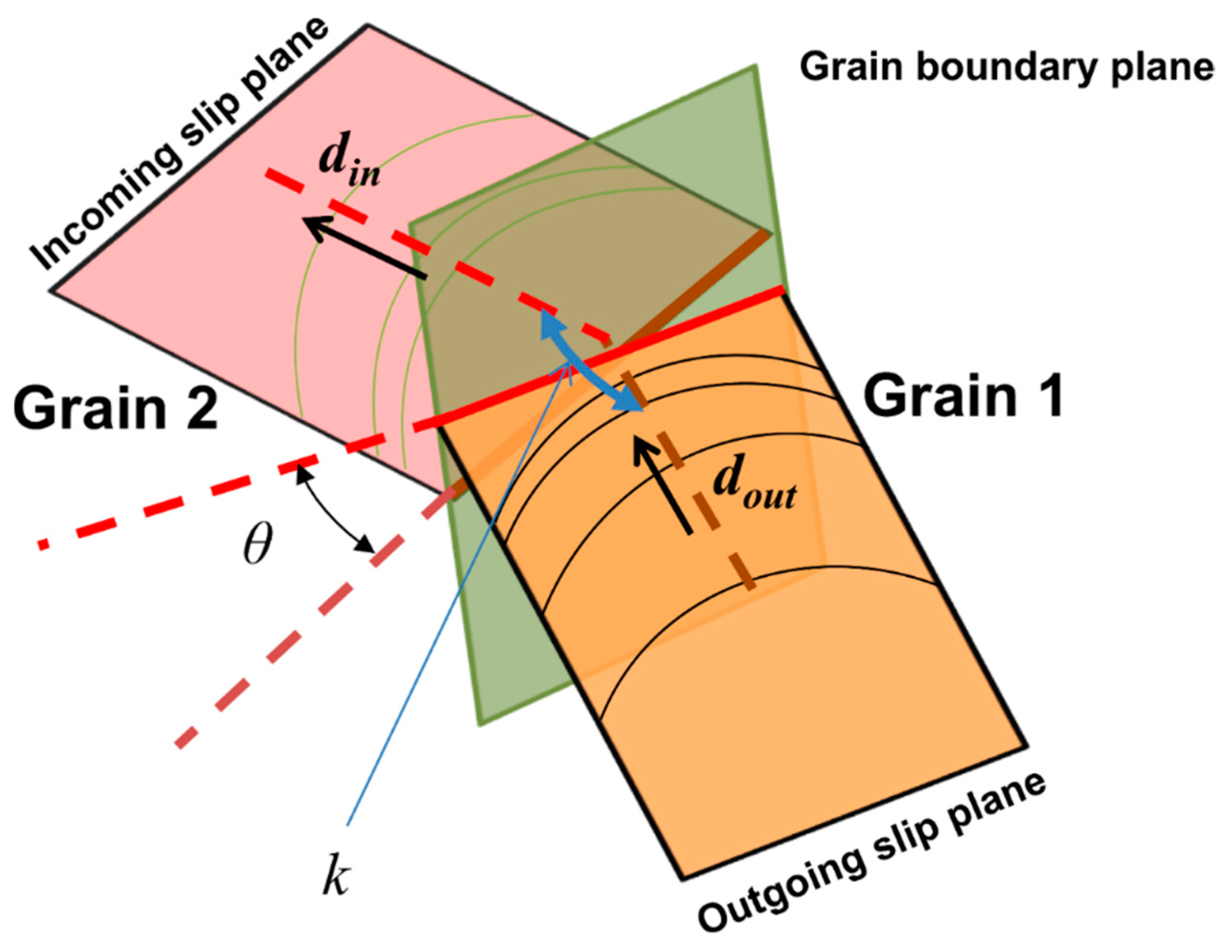
2.3. Slip Transmission

Three criteria are used to determine the occurrence of slip transfer: geometrical criteria [65], stress criteria [66], and dislocation density criteria [67].
In [29,65], the degree of coplanarity of slip systems is expressed by the mean of a parameter m = ( n i n n o u t ) ( d i n d o u t ) written as a function of the slip normal n and the slip direction d . The parameter m is a scalar number between 0 and 1. The upper bound 1 signifies that the grain boundary is transparent and the lower bound 0 means that the grain boundary is impenetrable. If the normal to the slip plane or the slip directions are in different directions, m can take on a negative value. However, slip transfer cannot occur. A schematic of the slip transfer across grain boundary is depicted in Figure 1.
There are two additional requirements. First, the resistance from the grain boundary must be overcome. In this work as in [65], the resistance is expressed as
τ GB = ( 1 m ) τ S
where τ S is the stress gradient term. τ S can be approximated by K L ( 1 + L 4 τ ¯ | τ ¯ | ) , where K is Hall–Petch constant, L is grain size, and τ ¯ is the gradient of effective stress. Secondly, the dislocation density in the outgoing slip system must be greater than in the incoming slip system. Once the above conditions are satisfied, the dislocation flux ρ ˙ f l u x α between two grains can be measured using the following equation
ρ ˙ f l u x α = p v ¯ α ρ M α p v ¯ g α ρ M α ( i n ) ρ M α ( o u t ) R
where R is the distance between two neighboring grains, p is a parameter used by Shi and Zirky [67], which can be expressed as
p = m α β ( τ o u t β τ C β ) i = 1 N ( m α i τ o u t i τ C i )
in which m α β is the geometrical parameter between two neighboring grains mentioned above and N is the number of all possible outgoing slip between two neighboring grains.

2.4. Implementation

To capture the strain/stress quantities and the dislocation density and to measure the strain and stress gradient as the result of the specimens deforming plastically, we use a spatial representative domain to represent the polycrystalline material. The domain is discretized into grains with spatial, size, and neighboring information using a 2D Voronoi tessellation diagram. Each Voronoi cell represents a grain with a stress state, from which the strain and dislocation densities are computed via the CDD-VPSC model. Then, the stress and strain fields (spatial) gradients can be numerically approximated using a moving least square method. Details on the technique can be found in [68].
We implemented the proposed models on a four-grain sample and verified that slip transmission and back-stress were captured accordingly. Figure 2 shows the stress-strain curves obtained from the simulations of the sample with— Σ 5 grain boundary (see grain 1 and grain 3), which accounts for grain slip transmission and impenetrable grain boundary (between grain 1 and grain 3). As expected, transmission occurs from slip system 13 in grain 1 to slip system 24 in grain 3 with a transferred mobile dislocation density in the order of 1012 m−2. The mobile dislocation density after slip transmission (red line) shows that the value in grain 1 is greater than for grain 3, after dislocation flux. Depending on the grain orientation, slip transmission may occur from grain 1 to grain 3 with further loading. The stress-strain curves also indicate a softening behavior. A possible explanation is that slip transmission induces more plasticity in comparison to the impenetrable boundary case because there is no resistance from dislocation pileups against grain boundaries.
The implementation of the back-stress model was verified by a set-up of two grains with tilt boundary (an array of edge dislocations). Then the shear stress was evaluated and compared to the discrete solution of the stress field around an infinite edge dislocation. This is shown in Figure 2b. The results show that the solution for the shear stress converges when x is close to the source of the dislocation (x < 150b) but that the simulations closely reproduce the discrete solution otherwise.

2.5. Samples Generation

To generate samples representing specimens with homogenous and gradient structures, we first obtain 2D Voronoi tessellations using NEPER, a specialized software package for polycrystal generation [69]. Then, we employed a grain growth algorithm embedded in the NEPER code to obtain the desired gradient structure. Details of the procedure can be found in [70,71,72].
Figure 3 depicts samples with constructed gradient structures and cells size ranging from hundreds of nanometers to tens of microns. Using 35 μm as the average grain size, specimens with homogeneous structures and randomly assigned crystal orientations (i.e., homogeneous texture) were constructed (Figure 4a). The grain size was chosen to be the same as the one used by Wu et al. [2] in their experiments. The equivalent grain size distribution along the y axis for specimens with homogeneous structures and gradient structures are shown in Figure 3c,d, respectively.

3. Results

After implementing the back-stress and slip transmission in the multiscale CDD-VPSC model, simulations were performed on IF steel specimens with homogeneous microstructures with three different randomly assigned crystallographic orientations. The parameters used in the simulations were taken from [39] and are summarized in Table 1 below.
Using the neighboring information and the information about the grain orientation, the distribution of the misorientation angle was plotted (see Figure A1 in Appendix C). The distribution of misorientation angles in the specimens with three different textures is somehow identical.
Figure 4 shows the predicted stress-strain curves of the IF steel specimens with homogeneous structures in tension and compression. Results are shown for three textures and compared when back-stress (LRS) and slip transmission (SLIP TRANS) are not considered. Experimental data on tensile tests obtained by Wu [2] on IF steel specimens with homogenous structures and 35 μm average grain size is also indicated.
Figure 4a shows that the stress-strain curve obtained from the simulations closely captures the mechanical behavior observed experimentally by [2], regardless of the initial texture. Upon implementing the LRS and SLIP TRANS in the model, the TCA of the tensile strength can be observed at the instability point. Otherwise, TCA is barely noticeable for the three different cases (see Figure 4b). This also shows that implementing the back-stress and slip transmission yields a higher strain hardening rate at the beginning and results in a tension-compression asymmetry. Figure 4b shows that deactivating the back-stress and slip transmission leads to a much lower initial strain hardening but yields a higher tensile strength and higher ductility values than the ones obtained experimentally. TCA of flow stress can be observed at a strain of around 1.5%, which is measured by using
TCA = 2 ( | σ C | | σ T | ) ( | σ C | + | σ T | )
One can also find slightly higher flow stress under compression than under tension test before 1%. Higher flow stress under compression (positive TCA) was also captured by experimental tests of low-carbon steel [36] but with a much more pronounced asymmetry. Although the role of the initial texture and the microstructure on TCA was not completely understood by [36], they hinted that the loading direction was the reason for the behavior. In Figure 4a, the tensile strength is 266 MPa at 0.55 strain (approximately). This is 11 MPa larger than the strength obtained in a compression test at a 0.45 strain (approximately). These values refer to the homogeneous cases for which the initial random grain orientation has no effect. That explains why we have one tensile value and one compression value for the three different initial textures with different random grain orientations.
Because our multiscale model, as proposed, does not consider the reduction of the cross-sectional area, the simulations yielded a smaller slope in the true stress-strain curve and consequently, the onset of instability from the simulations is seen to appear later than in the experimental curves. In future work, we plan to consider the decrease in the cross-sectional area in the model to improve the accuracy. Similarly, the predicted stress-strain curves on IF steel specimens with gradient structures when back-stress and slip transmission are implemented in the model are shown in Figure 5. Using a zoomed view at the onset of instabilities for each of the three initial textures, we measured the tensile strength and the strain at the instability point. Then we calculated an average value of tensile strength and position of instability for the three textures. They are shown in Table 2.
The values show that tension-compression asymmetry (TCA) of flow-stress exists and depends on the texture. However, the tensile strength value varies by less than 5 MPa for the three textures. In addition, in comparison to specimens with homogenous structures, specimens with gradient structures have a higher strength and strain hardening.
When compared to experimental data obtained by Wu et al. [2] for tests on homogenous specimens, one can see that our simulation results can predict the stress-strain curves of the tensile test of IF steel with the same average grain size, in trend if not values. Even though the simulation values for specimens with gradient structures (Figure 5a) show that they exceed those recorded in the experiments, the trend of the stress-strain curves is similar to the macroscopic behavior of grain size gradient IF steel under the tensile test given in [2]. In addition, the grain size spatial distribution and the size of the specimens used in the simulations differ from the experimental samples. The strain-stress curves in Figure 5a (all textures combined) show that the tension-compression asymmetry (TCA) of stress is negligible at early strain stages and that the texture plays a role in the TCA of the flow stress. Texture increases strength and strain hardening, while it was inferred from Figure 3 that for homogenous structures, it did not. Figure 5b–d show that the specimens with texture 1 and texture 3 have a flow stress under compression that is consistently larger than the one in tension. In the specimens with texture 3, the flow stress in compression is always larger than that in tension. For the specimens with texture 2, the initial strain hardening rate in compression is higher than in tension, until approximately a 10 % strain after which the strain hardening decreases leading to a lower tensile strength. This agrees with what is shown in experiments in [36], where before 10% strain, higher flow stress in compression is recorded. The onset of instability for a gradient structure occurs earlier than in a homogeneous structure. Depending on the initial texture, the onset of instabilities in gradient structures varies from 0.2~0.25 (strain).
Figure 6 shows the texture evolution of specimens with gradient structures in tension and compression. The texture evolution tracks the change of the misorientation angle with loading. Results are shown for two textures and compared to their respective initial texture. Results are recorded at 15 % strain. For both cases, the evolved texture shows the distribution of misorientation angle for a random texture without exhibiting a strong texture. In Figure 6a pertaining to specimens with texture 1, the evolution trend is similar in tension and compression. In specimens with texture 2 (Figure 6b), there is almost no change in the fraction of misorientation when the sample is under compression.
Figure 7a shows the average mobile dislocation density vs. equivalent strain curves for IF steel specimens in tension and compression. The average mobile dislocation density is measured using the total dislocation density in the polycrystal sample divided by the total number of grains. Results are shown for three initial textures. Results on specimens with gradient structures are compared to the reference cases, for specimens with homogeneous structures. The curves show that at early strain stages, the mobile dislocation density increases much faster for the homogeneous cases than for the gradient structures. With further straining, the trend reverses, i.e., the average mobile dislocation density in specimens with gradient structures surpasses that of the homogeneous structures.
Figure 7a shows that there is a slight difference in the evolution of the average mobile dislocation density depending on if the specimens are in tension or compression for samples with homogeneous and gradient structures. However, the GND density for samples with gradient structures in tension is much higher than for specimens in compression (Figure 7b). This contrasts with the GND density of samples with homogeneous structures, which are similar in tension and compression.
Regarding the effect of initial texture, Figure 7a shows that the average mobile dislocation density does not depend on the initial texture, and that is true for both the homogeneous and the gradient cases. However, one can infer from the figure that the local plastic deformation and dislocation density evolution depend on the initial texture. This is due to the slip transmission and back-stress. This means that even though all polycrystal samples have the same total dislocation density, different textures will result in different local strain distributions and strain gradients. This can also be seen from the evolution of GND density shown in Figure 7b which shows that the average GND density vs. equivalent strain curves varies depending on the initial texture. Here, the assumption was that the initial GND density was 0 before it increased with straining. Additionally, the average GND densities for specimens with gradient structures are significantly higher than for those with homogeneous microstructures.

4. Discussion

We discuss the effects of implementing slip transmission and back-stress in the model as they pertain to IF steel specimens with homogeneous and gradient structures, in tension and compression.

4.1. Homogeneous vs. Gradient Structures

Figure 8 shows how the microstructure affects the GND density and the stress gradient quantities. Specimens with homogenous structures have a narrow unimodal grain size distribution. As a result, the critical resolved shear stress needed to activate the slip is the same for each grain and all grains experience the same amount of deformation simultaneously. Specimens with gradient structures have bimodal or multimodal grain size distributions, with large and small grains. The dislocation motion is more difficult to activate in small grains with a size of 100 nm compared to in large grains with a size of 10 μm. Small grains contribute more to the strengthening of the polycrystal materials and large grains endure more plastic deformation. In homogeneous structures, all grains are in equal-axial shape and have the same opportunities to activate dislocation motions. This leads to a relatively uniform deformation which further lowers the GND densities and rises the stress gradient due to dislocation pileups against the grain boundary. This is shown in Figure 8a. In this work, the stress gradient was approximated using the moving least square method (see Section 2.4). Considering that there is less activation of slips in the finer grain region, one would expect a lower average mobile dislocation density in the gradient structure at the early strain stage (5%).
As a result, the inhomogeneous deformation between small (hard) grains and large (soft) grains increases the accumulation of GNDs which explains the higher average GND density in Figure 7b. At the early strain stage, these GNDs burst which prevents the motion of dislocations significantly and strengthens the polycrystal material. When the GND rate starts dropping ( 5% strain), the average mobile dislocation density in gradient structures surpasses that of homogeneous structures. When the local stress state increases, more dislocation activities are triggered in the small grains. The stress gradient term also plays an important role in preventing slip activation. Figure 8d shows that the stress in gradient structures is almost three times higher than in homogeneous structures (Figure 8c). In gradient structures (Figure 8d), the stress gradient increases along the y-direction, not in a random fashion.
Figure 9 shows how the stress gradient varies between two strain stages. Results are shown for gradient structures with texture 2 in tension and compression. Four grains undergoing slip transmission have been chosen and labeled in Figure 9. As can be seen from Figure 8a, the stress gradient due to dislocation pileups can be significantly relieved by the slip transmission from grains A, B, and C to the neighboring grains. Further straining will decrease the stress gradient. Grain D experiences an increase in stress gradient, which makes the small grain even harder to deform and causes local stress concentrations. This is in contrast to what happens during compression: when the sign of the resolved back-stress is altered and superposed to the resolved stress afterward, the value of resolved shear stress is lower than the critical resolved shear stress, and slip transmission cannot be triggered. Thus, grains A, B, and C experience only a minimal increase in stress gradient.
We note that for smaller grains such as grain D, a higher stress gradient could be induced due to small grain size (see the top and bottom surface in Figure 8d). In such a case, the slip transmission can occur due to the back-stress and the local grain orientation. When more slip transmissions occur in the nanograin (NG) region, a reduction of macroscopic flow-stress can ensue. Thus, for a homogeneous structure with random texture, the TCA is independent of the initial texture and the local grain orientation. For a gradient structure with random texture, TCA is determined by the local grain orientation and the grain size.

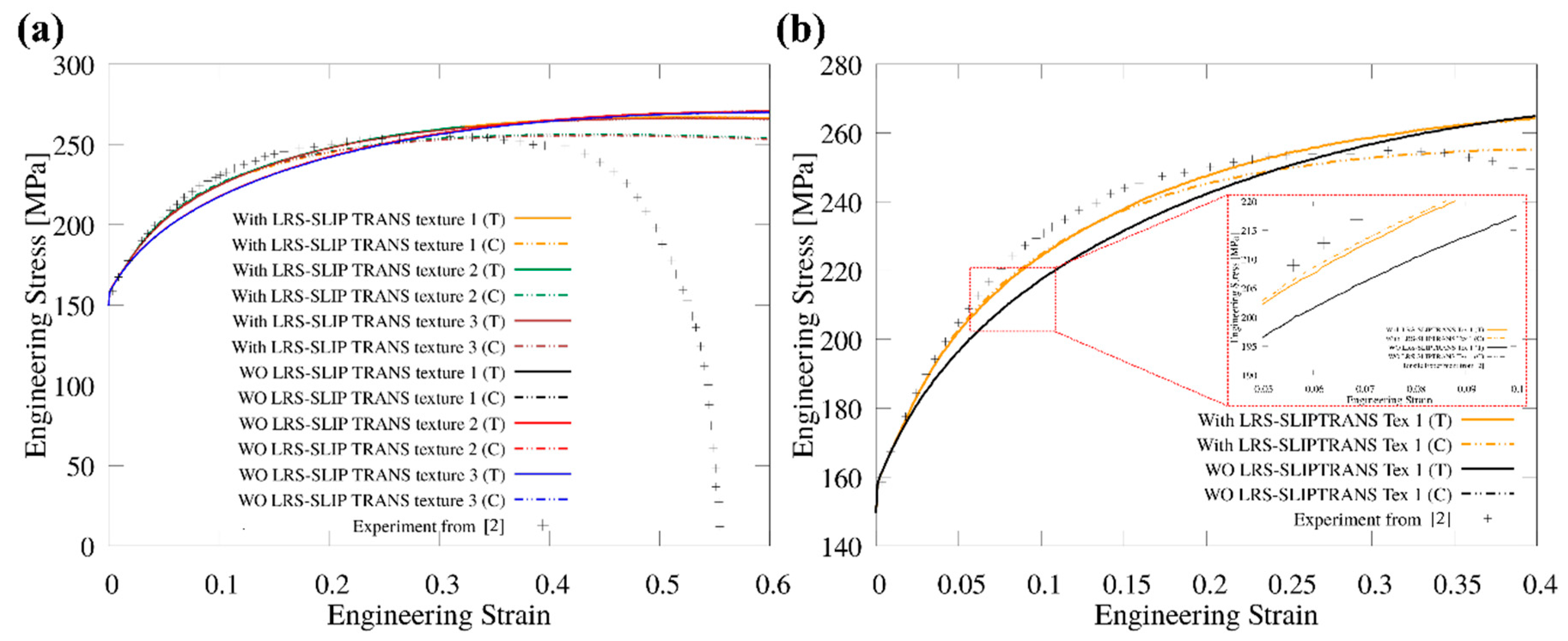
4.2. Slip Transmission and Relation to Tensile Strength and Ductility

Table 3 shows the number of slip transmissions that occurred in the entire sample, in the transient region, and the nano-grain region for specimens with homogeneous and gradient structures, for three textures. Table 3 also lists the average values of the tensile strength and ductility for the various cases, recorded at 20% strain. As explained previously, these are average values taken over three measurements.
The reason why the sum of the second and third column values does not equal the value of the first column is that we did not list the number of slip transmissions in the coarse-grain region. In addition, since homogenous structures have no transient nor nano-grain regions, we used the number of slip transmissions in the relative region. For example, if the number of slip transmissions that occurred in the nano-region—y [0.95, 1] and [0, 0.05] μm for a gradient case, we compared the number of slip transmissions that occurred in the same area—y [0.95, 1] and [0, 0.05]μm for the homogeneous case.

4.3. Slip Transmission in Homogeneous vs. Gradient Structures

The values of Table 3 show that a significantly smaller number of slip transmissions occur in specimens with gradient structures than in specimens with homogeneous structures. Dislocations in small grains within the nano-region (region with grains of nano-size. i.e., for which y > 90 µm and y < 10 µm) can barely travel through the grain boundary, regardless of the misorientation. That is because the stress gradient (refer to Figure 8d) arising in the region of nano-size grains is at least twice as much greater than that in the region of coarse grains. Even when the geometrical factor is satisfied, dislocations still need to overcome the huge resistance from dislocation pileups and grain boundaries. Most slip transmissions occur in the center of the specimens and are locally dependent on the inhomogeneous deformation.

4.4. Slip Transmission in Compression vs. Tension

The values also show that more slip transmission occurs in compression than in tension. Slip transmission leads to the reduction of pileups and therefore reduces the barrier for dislocation motion causing further softening. This could explain why the tensile strength is higher than that in compression for a homogeneous structure. For the homogenous structure, ductility is lower in compression than in tension. A possible reason may be that slip transmission affects the total dislocation density indirectly, so more slip transmission does not necessarily result in a higher total mobile dislocation density (refer to Figure 7a, which shows the mobile dislocation density vs. strain). When looking at the number of slip transmissions that occurred during the entire loading process, we find that although more slip transmission occurs in a homogeneous structure under compression, the mobile dislocation density under tension is much higher, possibly because tension activates more slips.
In contrast, for specimens with gradient structures, the probability to trigger slip transmission varies with the region. In particular, slip transmission is more difficult in the nano region (y > 90 µm and y < 10 µm), which possesses very fine grains of size around 200 nm. For the gradient structures, the flow stress under compression is higher than under tension at the early hardening stage (less than 20%) (refer to Figure 5). The occurrence of TCA at the early stage could be attributed to less slip transmission in the nano region (see Table 3) and fewer activated slips due to grain size. However, subsequent deformation and onset of instability are complicated by the redistribution of strain/stress occurring at the later strain stage. As a result, there is not a clear correlation between tensile strength value and slip transmission. Yet, the number of slip transmissions in the nano-region affects the onset of instability in gradient structures. Less slip transmission in the nano-region results in earlier instability (low ductility).

4.5. Tension-Compression Asymmetry (TCA)

Tension-compression asymmetry in IF steel specimens have been evaluated in relation to their microstructure, texture, back-stress, and subsequent slip/slip transmission. In this work, and unlike in [59,60], we did not consider non-gliding forces, so we assumed that the non-glide slip was not responsible for TCA. With the bursting of GNDs due to non-uniform straining, the magnitude of the resolved-back-stress increases. Depending on the superposition of the resolved back-stress and the resolved stress, slips and slips transmission can be triggered.
Figure 10 shows the resolved back-stress in specimens with gradient structures under tension and compression. Results are recorded at 2.5 % strain. The values of the back-stress vary between ±200 MPa., while the critical shear stress (CRSS) is in the range of [90, 500] MPa. These values are the output of the simulations for slip system 16 for all grains at the 2% strain stage. Simulations track CRSS values on any slip system in any grain. This indicates that the resolved back-stress can aid or prevent the slip and the slip transmission, leading to a different strain hardening at the macroscopic scale.
The values of tensile strength and ductility in Table 3 show that gradient structures exhibit much less tension-compression asymmetry than homogeneous structures. One reason may be that homogeneous structures have grain size in the order of 1μm so slips and slip transmissions occur more easily. Also, all equal axial grains have the same chance to deform, resulting in a more uniform deformation than for gradient structures. Thus, the magnitude of GND density and stress gradient in homogeneous specimens can be expected to be much lower than for a gradient specimen. Slip and slip transmission can easily be activated with low GND density and stress gradient. The critical resolved shear stress on slip system [-2-1-1] (-111) in homogeneous structures is around 70 MPa. This is much lower than the critical resolved back-stress (in order of 100 MPa) at approximately 0.1 % strain. Again, these values are retrieved as the output of our simulations, which tracks CRSS for any slip system in any grain. For homogeneous structures, the back-stress is negligible, initially. For gradient structures, the magnitude of the resolved shear stress (see Figure 10) is comparable to the critical resolved shear stress. The larger resolved back-stress is a result of non-uniform straining (formed GNDs) and the grain size, which can alter the activation of slips and slip transmissions depending on the sign.
With the results of the simulations, we were able to show that the local orientation played a key role in plastic deformation and macroscopic behavior of IF steel specimens. For samples with homogeneous structures, TCA does not depend on the initial texture if the texture has a random orientation. For samples with gradient structures, TCA is more sensitive to the local texture and particularly for the grains in the nano-region, even though the distribution of misorientation angles of three different samples are almost identical.
Producing a gradient microstructure using severe plastic deformation (SPD) such as SMAT will inevitably introduce a strong texture or grain orientation gradient into the texture of the sample [73]. To show this, we conducted another simulation using a texture gradient similar to the one reported in [74] for a low carbon steel specimen. Because the sample size differs from [74], we scaled the thickness of different regions with different fractions of the {110} textures The results are shown in Figure 11a and point that- an earlier onset of TCA occurs at the strain 5% and the value of TCA increases with further loading for the specimens with gradient grain size and gradient texture. This indicates that the local grain orientation in the nano layer and the gradient layer has a significant effect on the TCA behavior. Thus, a deeper investigation of the effect of local texture and texture gradient on deformation as well as a better understanding of the synergetic effects between the spatial distribution of grain size and grain orientation on the material macroscopic behavior will eventually lead to the development of new gradient materials.
Comparing the simulation results with the experimental data on low carbon steel by Koizumi et al. [36], Figure 11b shows that the predicted TCA value is lower and even in a more pronounced way, for the random texture. This can be attributed to the assumption of texture as well as the initial dislocation density and GND density.
Koizumi et al. have also shown that the loading direction (in the initial texture) could affect the magnitude and trend of the TCA in flow stress. Details of sample preparation are not given in [36], but residual stresses will likely exist in raw samples with no heat treatment. In the work by Chen et al. [35] on 3D printed stainless steel, there is a significant decrease in TCA when the sample is annealed. This could be explained by the release of residual stress in the homogeneous texture. Our simulations on specimens with gradient structures show that the TCA behavior is captured, and although the magnitude of TCA is much lower than the data recorded in experiments, it exhibits the same trend, i.e., a small hump at the initial strain stage followed by increasing TCA. The low initial TCA value predicted by the simulations could be attributed to a low dislocation capacity of the fine grains at the top and bottom surface. These fine grains can bare almost no plastic deformation and as a result, a stress concentration arises at the surface, regardless of the grain orientation. However, the strong texture in the transient and in the central region can lead to a very different deformation gradient, which could in turn affect the TCA.

5. Conclusions

In this work, we improved on the multi-scale CDD-VPSC framework we previously proposed [39,68] by implementing a back-stress and slip transmission quantity in the constitutive model. With that, our simulations predicted the deformation of IF steel specimens under tension and compression, with three initial textures and in two specific grain-size regions (transient and nano). Comparisons between specimens with homogeneous and gradient structures were made. The following conclusions can be inferred from this study:
(1)
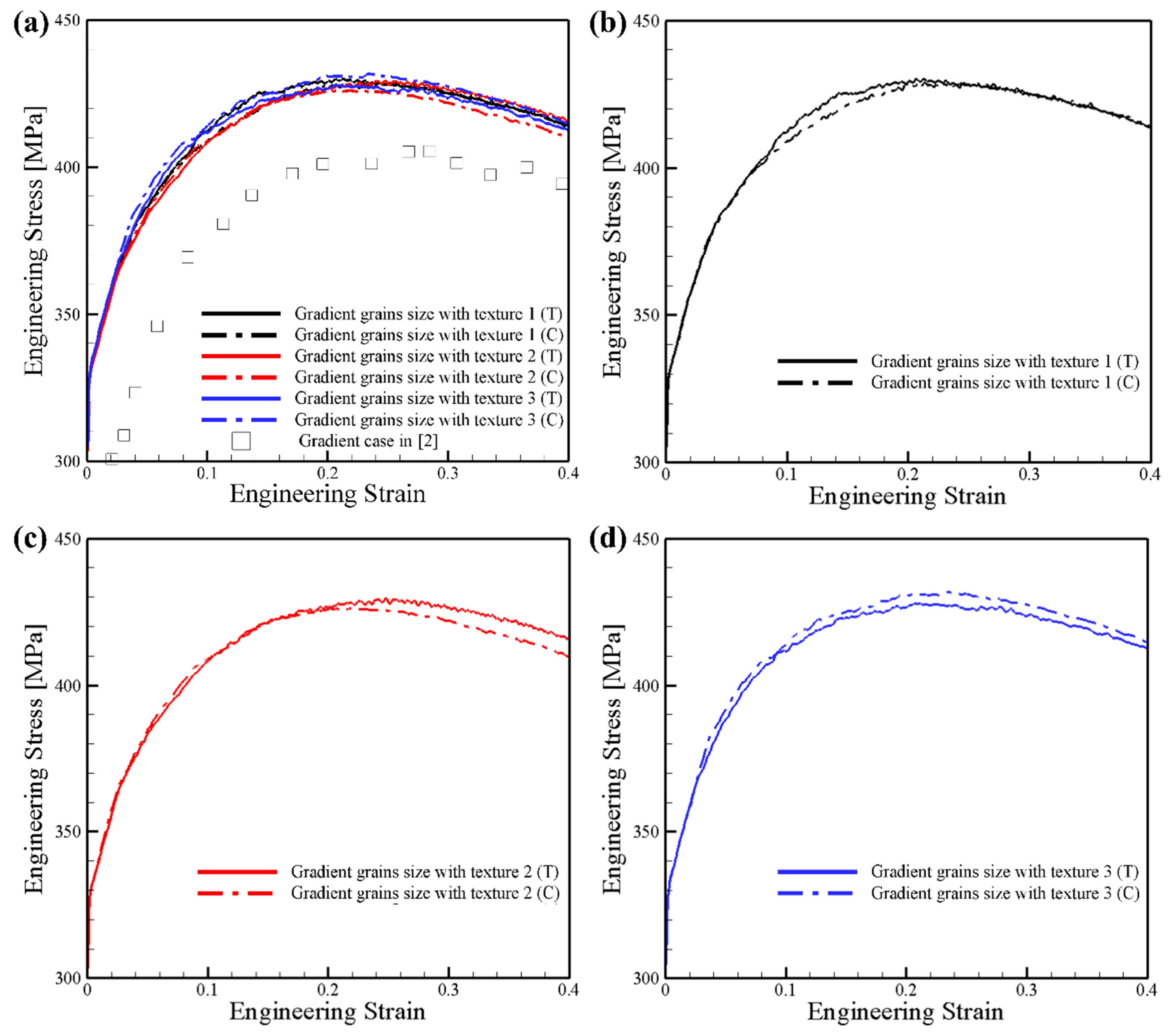
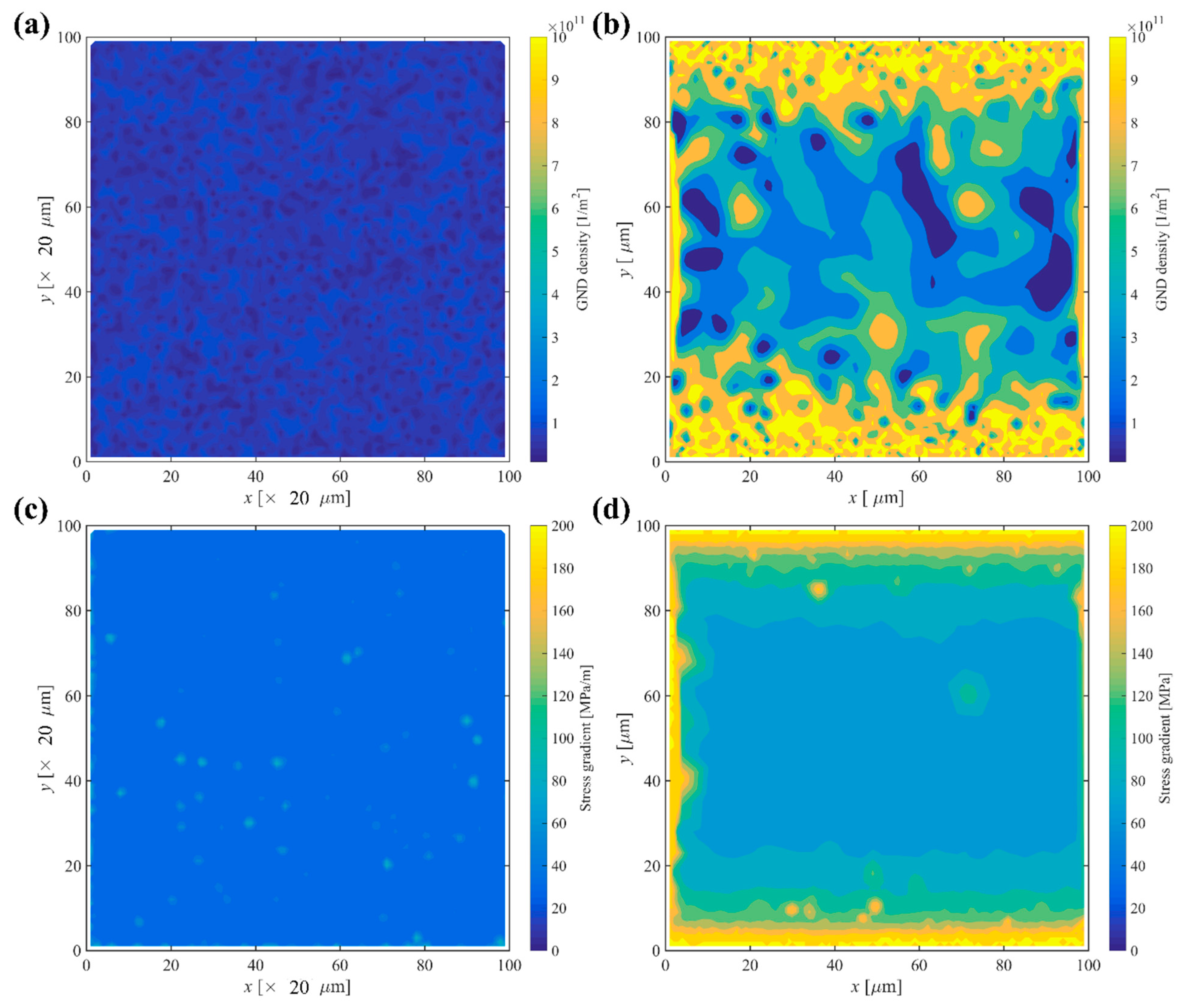
Specimens with gradient texture cause deformation gradient along the grain size gradient direction. Plastic deformation occurs first in the coarse grains in the center region. Then it gradually expands to the transient and the nano region. Local inhomogeneous deformations were more easily induced for microstructures with a bi-or multi-modal grain size distribution and gradient size distribution along the y-direction.
(2)
There is no clear correlation between slip transmission and tensile strength. More slip transmission in the nano region could explain the delay in the onset of instability.
(3)
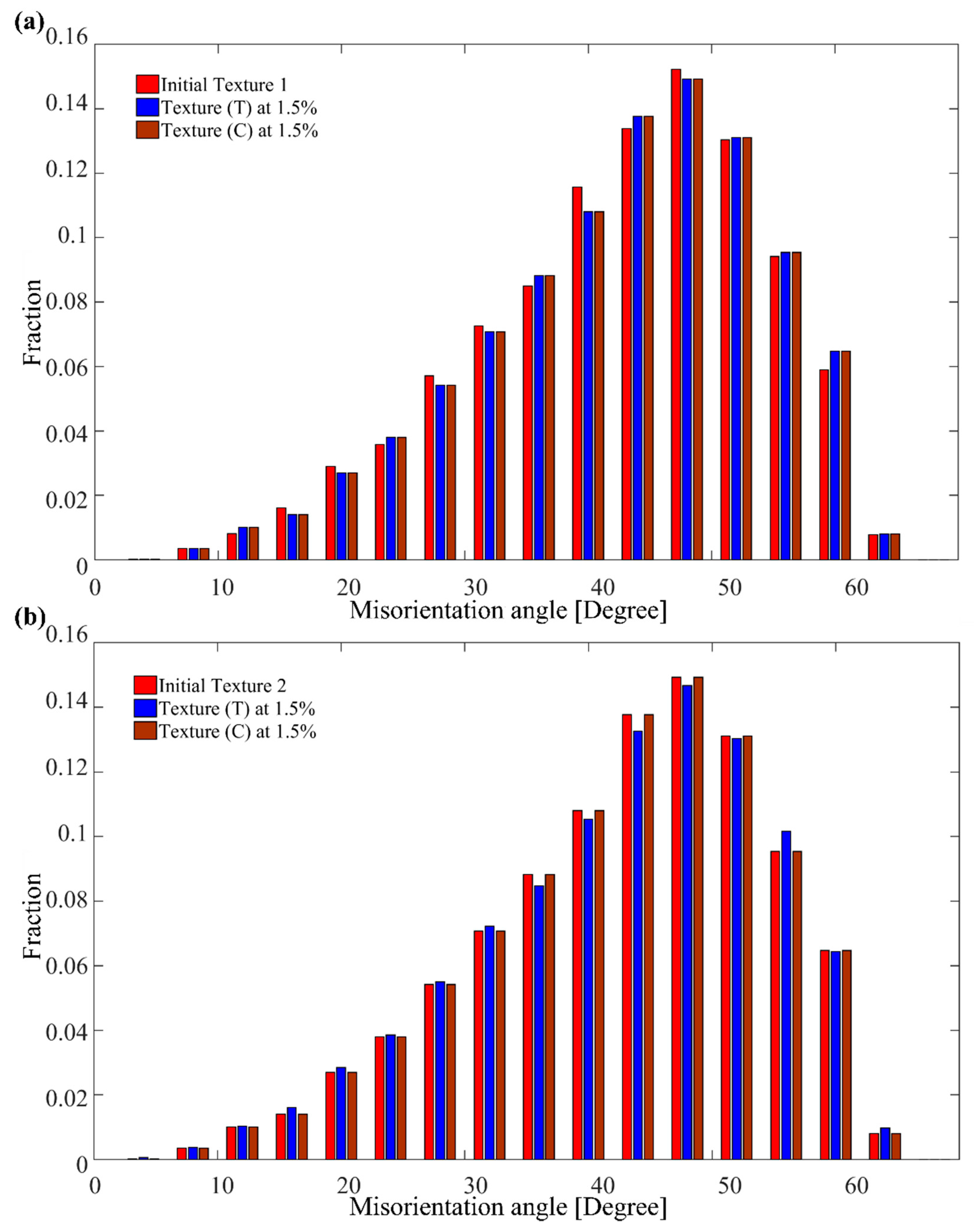
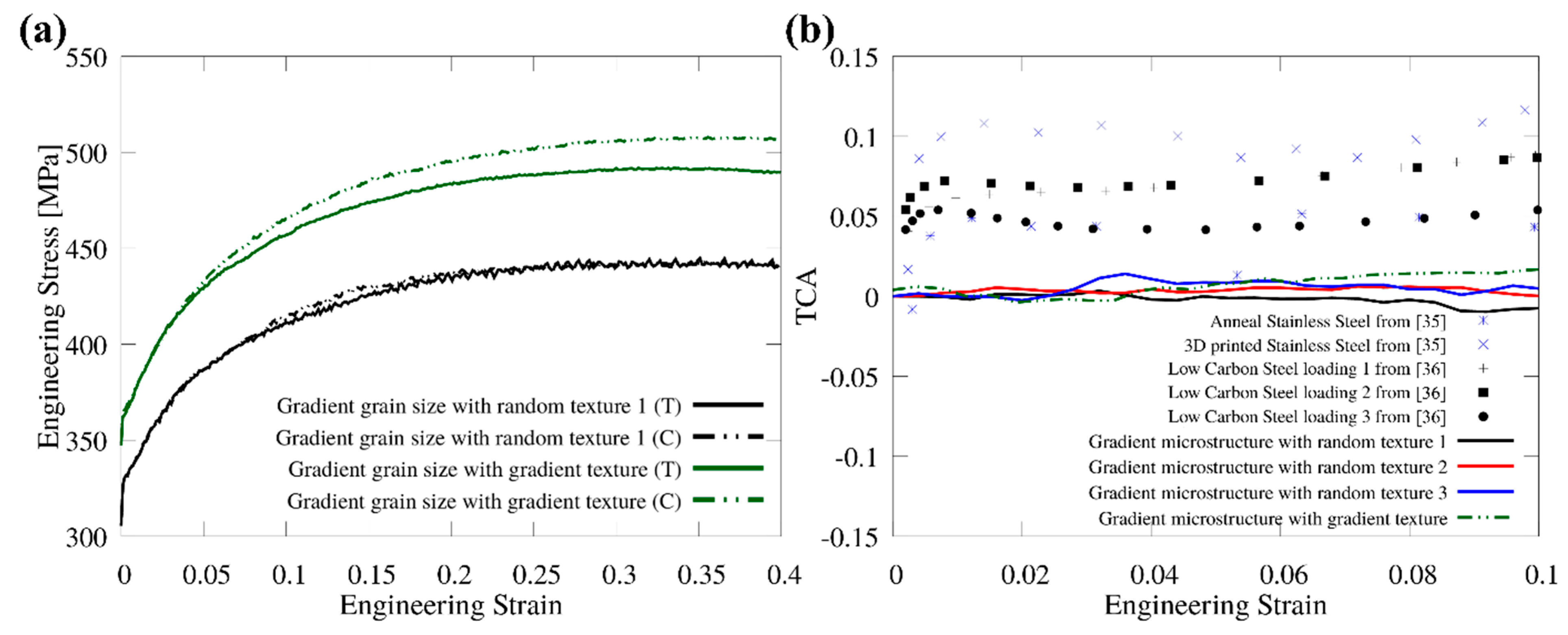
The back-stress quantity which arises from dislocations and slip transmission causes tension-compression asymmetry (TCA) behavior. TCA exists in specimens with homogeneous microstructure and with gradient microstructure. The simulations show that the predicted TCA values are lower than recorded experimentally. The initial texture of the specimens plays a predominant role in TCA.

Author Contributions

Methodology, A.R. and H.L.; validation, H.L.; formal analysis, H.L. and A.R.; writing—original draft preparation, H.L.; writing—review and editing, A.R.; visualization, H.L.; funding acquisition, H.L. All authors have read and agreed to the published version of the manuscript.

Funding

This research was funded by the National Natural Science Foundation of China, grant number 52101008, the Fundamental Research Funds for the Central Universities, grant number 3132022176, and the Start-up foundation of Xinghai talent plan-Dalian Maritime University, grant number 02502421.

Institutional Review Board Statement

Not applicable.

Informed Consent Statement

Not applicable.

Data Availability Statement

Not applicable.

Conflicts of Interest

The authors declare no conflict of interest.

Appendix A

The evolution of the dislocation density in the CDD model can be expressed by Equation (A1) for mobile dislocation ( ρ ˙ M α ) and by Equation (A2) for immobile dislocation ( ρ ˙ I M α )
ρ ˙ M α = q 1 ρ M α v ¯ g α l ˜ g α q 2 2 R c ρ M α 2 v g α q 3 ρ M α v ¯ g α l ˜ g α + q 4 τ α τ c r α r ρ I M α v ¯ g α l ˜ g α + q 5 β = 1 N P α β ρ M β v ¯ g α l ˜ g α q 6 R c ρ M α ρ I M α v ¯ g α q 7 R c 3 ρ M α ρ I M α 2 v ¯ g α
ρ ˙ I M α = q 3 ρ M α v ¯ g α l ˜ g α q 4 ( | τ α | τ c r α ) r ρ I M α v ¯ g α l ˜ g α q 6 R c ρ M α ρ I M α v ¯ g α + q 7 R c 3 ρ M α ( ρ I M α ) 2 v ¯ g α
In Equations (A1) and (A2), q 1 ~ q 7 are coefficients obtained by fitting the evolution equation with discrete dislocation dynamics and single-crystal tensile tests. Terms 1 and 3 describe the increase of the mobile dislocation density due to multiplication and mobilization of immobile dislocation respectively. The annihilation of two mobile dislocations is captured in term 2. Mobile dislocation can also interact with other defects, leading to a reduction of mobile dislocations. The immobilization of moving dislocation, absorption of mobile dislocation by grain boundary, and dipole formation are considered in terms 3, 6, and 7. In this work, we used the coefficients from [47,63]).
l ˜ g α is the mean free path of mobile dislocation on slip system α , which can be expressed as
l ˜ g α = c β W α β ( ρ M β + ρ I M β + | | ρ GND β | | )
where c is a numerical constant in the order of 10, W α β is a weight matrix similar to Ω α β . | | ρ GND β | | is the effective density of GNDs on slip system β written as:
| | ρ G N D β | | = 1 b A A  
where A is the Nye’s tensor [74] that can be approximated by A curl   ( F p ) curl   ( D p ) , where D p = i N γ ( i ) s ( i ) n ( i ) [75,76,77], and where the derivative of D p over space is approximated by a moving least square method.
τ c r α is the critical resolved shear stress needed to activate the dislocation motion. It can be decomposed as
τ c r α   = τ 0 α + τ H α + τ S α
where τ 0 α is an internal friction term that describes the minimum stress to move a dislocation, τ H α is a hardening term, which is dependent on current total dislocation density. The last term τ S α is a size-effect term, which describes the resistant effect arising from the dislocation pileups against the grain boundary. In the present work, we implement in our framework a simplified linear version of the stress gradient model such as
τ S α =     K L ( 1 + L 4 τ ¯ | τ ¯ | )  
where K is Hall–Petch constant, τ ¯ is the spatial gradient of effective stress, L stands for the grain size, and L   is the average length of dislocation obstacles spacing. L is also treated as the grain size.
R c is the critical radius for reactions set to be 15 times the Burgers vector, r is 0.5, and P α β is a cross-slip probability matrix describing the probability of screw dislocations cross-slip from slip system β to slip system α . When the Burgers vector on α -system and β -system are parallel, cross slip is possible and can be determined stochastically using a Monte-Carlo analysis [77].

Appendix B

In the visco-plasticity self-consistent (VPSC) model, each grain is treated as an ellipsoidal visco-plastic inclusion embedded in a homogenous effective matrix. The deformation of each grain is determined by rate-dependent crystal plasticity including slip and twinning. The constitutive behavior at the local level is written as
ε ˙ i j ( x ¯ ) = γ ˙ 0 α = 1 N m i j ( α ) ( m k l ( α ) σ k l ( x ¯ ) τ c r ( α ) ) n
where γ ˙ 0 is the reference strain rate, m i j ( α ) is the Schmid tensor associated with slip systems, n is a strain rate sensitivity exponent equal to 1/m.
The linearized form of Equation (A9) I inside the domain of grain (r) is:
ε ˙ i j ( x ¯ ) = M i j k l ( r ) σ k l ( x ¯ ) + ε ˙ i j 0 ( r )
where M i j k l ( r ) is the viscoplastic compliance and ε ˙ i j 0 ( r ) is the back-extrapolated term of grain (r). Similarly, the average strain rate is related to the stress in each grain via the expression
ε ˙ i j = M i j k l σ k l + ε ˙ i j 0  
At the polycrystal level, the relation between the macroscopic strain rate and the stress is
E ˙ i j = M ¯ i j k l k l + E ˙ i j 0  
where M ¯ i j k l and E ˙ i j 0 are respectively the macroscopic viscoplastic compliance and the back-extrapolated term. Invoking the concept of equivalent inclusion [63], the local constitutive behavior can be rewritten in terms of macroscopic compliance with the inhomogeneity included in an Eigenstrain rate term ε ˙ i j * , as
ε ˙ i j = M ¯ i j k l σ k l + E ˙ i j 0 + ε ˙ i j 0  
Thus, the interaction of local and the macroscopic level can be expressed as
( ε ˙ i j E ˙ i j ) ε ˙ i j 0 = M ¯ i j k l ( σ k l k l )  

Appendix C

Additional supporting figures for the misorientation angle distribution for three initial textures.
Figure A1. Effect of initial texture on distribution of misorientation angle (a) texture 1; (b) texture 2; (c) texture 3; (d) all combined.
Crystals 12 00889 g0a1

References

  1. Lu, K. Making strong nanomaterials ductile with gradients: Microstructures that increase metal crystallite size from nanoscale with surface depth are both strong and ductile. Science 2014, 345, 1455–1456. [Google Scholar] [CrossRef] [PubMed]
  2. Wu, X.; Jiang, P.; Chen, L.; Yuan, F.; Zhu, Y.T. Extraordinary strain hardening by gradient structure. Proc. Natl. Acad. Sci. USA 2014, 111, 7197–7201. [Google Scholar] [CrossRef] [PubMed] [Green Version]
  3. Shao, C.W.; Zhang, P.; Zhu, Y.K.; Zhang, Z.J.; Tian, Y.Z.; Zhang, Z.F. Simultaneous improvement of strength and plasticity: Additional work-hardening from gradient microstructure. Acta Mater. 2018, 145, 413–428. [Google Scholar] [CrossRef]
  4. Wu, X.L.; Yang, M.X.; Yuan, F.P.; Chen, L.; Zhu, Y.T. Combining gradient structure and TRIP effect to produce austenite stainless steel with high strength and ductility. Acta Mater. 2016, 112, 337–346. [Google Scholar] [CrossRef] [Green Version]
  5. Wu, Y.; Guelorget, B.; Sun, Z.; Déturche, R.; Retraint, D. Characterization of gradient properties generated by SMAT for a biomedical grade 316L stainless steel. Mater. Charact. 2019, 155, 109788. [Google Scholar] [CrossRef]
  6. Wang, L.; Li, B.; Shi, Y.; Huang, G.; Song, W.; Li, S. Optimizing mechanical properties of gradient-structured low-carbon steel by manipulating grain size distribution. Mater. Sci. Eng. A 2019, 743, 309–313. [Google Scholar] [CrossRef]
  7. Shi, Y.; Li, B.; Gao, F.; Wang, L.; Qin, F.; Liu, H.; Li, S. An outstanding synergy of high strength and ductility in gradient structured low-carbon steel. Materialia 2019, 5, 100181. [Google Scholar] [CrossRef]
  8. Jamalian, M.; Hamid, M.; De Vincentis, N.; Buck, Q.; Field, D.P.; Zbib, H.M. Creation of heterogeneous microstructures in copper using high-pressure torsion to enhance mechanical properties. Mater. Sci. Eng. A 2019, 756, 142–148. [Google Scholar] [CrossRef]
  9. Kang, J.Y.; Kim, J.G.; Park, H.W.; Kim, H.S. Multiscale architectured materials with composition and grain size gradients manufactured using high-pressure torsion. Sci. Rep. 2016, 6, 26590. [Google Scholar] [CrossRef]
  10. Ma, E.; Zhu, T. Towards strength–ductility synergy through the design of heterogeneous nanostructures in metals. Mater. Today 2017, 20, 323–331. [Google Scholar] [CrossRef]
  11. Li, J.; Cao, Y.; Gao, B.; Li, Y.; Zhu, Y. Superior strength and ductility of 316L stainless steel with heterogeneous lamella structure. J. Mater. Sci. 2018, 53, 10442–10456. [Google Scholar] [CrossRef]
  12. Li, J.; Gao, B.; Huang, Z.; Zhou, H.; Mao, Q.; Li, Y. Design for strength-ductility synergy of 316L stainless steel with heterogeneous lamella structure through medium cold rolling and annealing. Vacuum 2018, 157, 128–135. [Google Scholar] [CrossRef]
  13. Wang, P.; Xiang, Y.; Wang, X.; Liu, Z.; Qu, S.; Zhuang, Z. New insight for mechanical properties of metals processed by severe plastic deformation. Int. J. Plast. 2019, 123, 22–37. [Google Scholar] [CrossRef]
  14. Wang, Y.F.; Wang, M.S.; Fang, X.T.; Guo, F.J.; Liu, H.Q.; Scattergood, R.O.; Huang, C.X.; Zhu, Y.T. Extra strengthening in a coarse/ultrafine grained laminate: Role of gradient interfaces. Int. J. Plast. 2019, 123, 196–207. [Google Scholar] [CrossRef]
  15. Roland, T.; Retraint, D.; Lu, K.; Lu, J. Fatigue life improvement through surface nanostructuring of stainless steel by means of surface mechanical attrition treatment. Scr. Mater. 2006, 54, 1949–1954. [Google Scholar] [CrossRef]
  16. Yang, M.; Pan, Y.; Yuan, F.; Zhu, Y.; Wu, X. Back stress strengthening and strain hardening in gradient structure. Mater. Res. Lett. 2016, 4, 145–151. [Google Scholar] [CrossRef]
  17. Yang, X.; Ma, X.; Moering, J.; Zhou, H.; Wang, W.; Gong, Y.; Tao, J.; Zhu, Y.; Zhu, X. Influence of gradient structure volume fraction on the mechanical properties of pure copper. Mater. Sci. Eng. A 2015, 645, 280–285. [Google Scholar] [CrossRef]
  18. Fang, T.H.; Li, W.L.; Tao, N.R.; Lu, K. Revealing extraordinary intrinsic tensile plasticity in gradient nano-grained copper. Science 2011, 331, 1587–1590. [Google Scholar] [CrossRef] [Green Version]
  19. Yan, X.; Meng, X.; Luo, L.; Jing, Y.; Yi, G.; Lu, J.; Liu, Y. Mechanical behaviour of AZ31 magnesium alloy with the laminate and gradient structure. Philos. Mag. 2019, 99, 3059–3077. [Google Scholar] [CrossRef]
  20. Kale, C.; Turnage, S.; Avery, D.Z.; El Kadiri, H.; Jordon, J.B.; Solanki, K.N. Towards dynamic tension-compression asymmetry and relative deformation mechanisms in magnesium. Materialia 2020, 9, 100543. [Google Scholar] [CrossRef]
  21. Ning, J.L.; Xu, B.; Feng, Y.L.; Li, X.D.; Li, X.K.; Tong, W.P. Tension–Compression Yield Asymmetry Influenced by the Variable Deformation Modes in Gradient Structure Mg Alloys. Acta Metall. Sin. (Engl. Lett.) 2020, 33, 252–266. [Google Scholar] [CrossRef] [Green Version]
  22. Lin, J.B.; Ren, W.J.; Wang, X.Y.; Ma, L.F. Tension–compression asymmetry in yield strength and hardening behaviour of as-extruded AZ31 alloy. Mater. Sci. Technol. 2016, 32, 1855–1860. [Google Scholar] [CrossRef]
  23. Habib, S.A.; Khan, A.S.; Gnäupel-Herold, T.; Lloyd, J.T.; Schoenfeld, S.E. Anisotropy, tension-compression asymmetry and texture evolution of a rare-earth-containing magnesium alloy sheet, ZEK100, at different strain rates and temperatures: Experiments and modeling. Int. J. Plast. 2017, 95, 163–190. [Google Scholar] [CrossRef]
  24. Kim, J.Y.; Greer, J.R. Tensile and compressive behavior of gold and molybdenum single crystals at the nano-scale. Acta Mater. 2009, 57, 5245–5253. [Google Scholar] [CrossRef]
  25. Alkan, S.; Sehitoglu, H. Non-Schmid response of Fe3Al: The twin-antitwin slip asymmetry and non-glide shear stress effects. Acta Mater. 2017, 125, 550–566. [Google Scholar] [CrossRef] [Green Version]
  26. Xing, Z.; Fan, H.; Tang, J.; Wang, B.; Kang, G. Molecular dynamics simulation on the cyclic deformation of magnesium single crystals. Comput. Mater. Sci. 2021, 186, 110003. [Google Scholar] [CrossRef]
  27. Kurukuri, S.; Worswick, M.J.; Tari, D.G.; Mishra, R.K.; Carter, J.T. Rate sensitivity and tension-compression asymmetry in AZ31B magnesium alloy sheet. Philos. Trans. R. Soc. A Math. Phys. Eng. Sci. 2014, 372, 20130216. [Google Scholar] [CrossRef]
  28. Ahmadikia, B.; Kumar, M.A.; Beyerlein, I.J. Effect of neighboring grain orientation on strain localization in slip bands in HCP materials. Int. J. Plast. 2021, 144, 103026. [Google Scholar] [CrossRef]
  29. Wang, Z.Q.; Beyerlein, I.J. An atomistically-informed dislocation dynamics model for the plastic anisotropy and tension-compression asymmetry of BCC metals. Int. J. Plast. 2011, 27, 1471–1484. [Google Scholar] [CrossRef]
  30. Cho, H.; Bronkhorst, C.A.; Mourad, H.M.; Mayeur, J.R.; Luscher, D.J. Anomalous plasticity of body-centered-cubic crystals with non-Schmid effect. Int. J. Solids Struct. 2018, 139–140, 138–149. [Google Scholar] [CrossRef] [Green Version]
  31. Gröger, R.; Vitek, V. Impact of non-Schmid stress components present in the yield criterion for bcc metals on the activity of {110}<111> slip systems. Comput. Mater. Sci. 2019, 159, 297–305. [Google Scholar] [CrossRef]
  32. Long, J.; Pan, Q.; Tao, N.; Lu, L. Residual stress induced tension-compression asymmetry of gradient nanograined copper. Mater. Res. Lett. 2018, 6, 456–461. [Google Scholar] [CrossRef]
  33. Maeda, T.; Noma, N.; Kuwabara, T.; Barlat, F.; Korkolis, Y.P. Experimental Verification of the Tension-Compression Asymmetry of the Flow Stresses of a High Strength Steel Sheet. Procedia Eng. 2017, 207, 1976–1981. [Google Scholar] [CrossRef]
  34. Chen, W.; Voisin, T.; Zhang, Y.; Florien, J.B.; Spadaccini, C.M.; McDowell, D.L.; Zhu, T.; Wang, Y.M. Microscale residual stresses in additively manufactured stainless steel. Nat. Commun. 2019, 10, 4338. [Google Scholar] [CrossRef] [Green Version]
  35. Koizumi, T.; Kuroda, M. Evaluation of tension-compression asymmetry of a low-carbon steel sheet using a modified classical compression test method. J. Phys. Conf. Ser. 2018, 1063, 012167. [Google Scholar] [CrossRef] [Green Version]
  36. Lehto, P.; Remes, H.; Saukkonen, T.; Hänninen, H.; Romanoff, J. Influence of grain size distribution on the Hall-Petch relationship of welded structural steel. Mater. Sci. Eng. A 2014, 592, 28–39. [Google Scholar] [CrossRef] [Green Version]
  37. Li, J.; Weng, G.J.; Chen, S.; Wu, X. On strain hardening mechanism in gradient nanostructures. Int. J. Plast. 2017, 88, 89–107. [Google Scholar] [CrossRef] [Green Version]
  38. Lyu, H.; Hamid, M.; Ruimi, A.; Zbib, H.M. Stress/strain gradient plasticity model for size effects in heterogeneous nano-microstructures. Int. J. Plast. 2017, 97, 46–63. [Google Scholar] [CrossRef]
  39. Ma, A.; Roters, F.; Raabe, D. A dislocation density based constitutive model for crystal plasticity FEM including geometrically necessary dislocations. Acta Mater. 2006, 54, 2169–2179. [Google Scholar] [CrossRef]
  40. Zhao, J.; Lu, X.; Yuan, F.; Kan, Q.; Qu, S.; Kang, G.; Zhang, X. Multiple mechanism based constitutive modeling of gradient nanograined material. Int. J. Plast. 2020, 125, 314–330. [Google Scholar] [CrossRef]
  41. Xiao, X.; Chen, L.; Yu, L.; Duan, H. Modelling nano-indentation of ion-irradiated FCC single crystals by strain-gradient crystal plasticity theory. Int. J. Plast. 2019, 116, 216–231. [Google Scholar] [CrossRef]
  42. Fleck, N.A.; Muller, G.M.; Ashby, M.F.; Hutchinson, J.W. Strain gradient plasticity: Theory and experiment. Acta Metall. Mater. 1994, 42, 475–487. [Google Scholar] [CrossRef]
  43. Hirth, J.P. Dislocation pileups in the presence of stress gradients. Philos. Mag. 2006, 86, 3959–3963. [Google Scholar] [CrossRef]
  44. Chakravarthy, S.S.; Curtin, W.A. Stress-gradient plasticity. Proc. Natl. Acad. Sci. USA 2011, 108, 15716–15720. [Google Scholar] [CrossRef] [Green Version]
  45. Liu, D.; He, Y.; Zhang, B.; Shen, L. A continuum theory of stress gradient plasticity based on the dislocation pile-up model. Acta Mater. 2014, 80, 350–364. [Google Scholar] [CrossRef]
  46. Taheri-Nassaj, N.; Zbib, H.M. On dislocation pileups and stress-gradient dependent plastic flow. Int. J. Plast. 2015, 74, 1–16. [Google Scholar] [CrossRef]
  47. Lyu, H.; Ruimi, A.; Zbib, H.M. A dislocation-based model for deformation and size effect in multi-phase steels. Int. J. Plast. 2015, 72, 44–59. [Google Scholar] [CrossRef]
  48. Lyu, H.; Taheri-Nassaj, N.; Zbib, H.M. A multiscale gradient-dependent plasticity model for size effects. Philos. Mag. 2016, 96, 1883–1908. [Google Scholar] [CrossRef]
  49. Akarapu, S. Dislocation Interactions with Interfaces; Washington State University: Washington, DC, USA, 2009. [Google Scholar]
  50. Lim, L.C.; Raj, R. Continuity of slip screw and mixed crystal dislocations across bicrystals of nickel at 573 K. Acta Metall. 1985, 33, 1577–1583. [Google Scholar] [CrossRef]
  51. Zaefferer, S.; Kuo, J.C.; Zhao, Z.; Winning, M.; Raabe, D. On the influence of the grain boundary misorientation on the plastic deformation of aluminum bicrystals. Acta Mater. 2003, 51, 4719–4735. [Google Scholar] [CrossRef]
  52. Priester, L. Grain Boundaries: From Theory to Engineering; Springer: Berlin/Heidelberg, Germany, 2013; Volume 172, ISBN 978-94-007-4968-9. [Google Scholar]
  53. Kacher, J.; Eftink, B.P.; Cui, B.; Robertson, I.M. Dislocation interactions with grain boundaries. Curr. Opin. Solid State Mater. Sci. 2014, 18, 227–243. [Google Scholar] [CrossRef]
  54. Hamid, M.; Lyu, H.; Schuessler, B.J.; Wo, P.C.; Zbib, H.M. Modeling and characterization of grain boundaries and slip transmission in dislocation density-based crystal plasticity. Crystals 2017, 7, 152. [Google Scholar] [CrossRef] [Green Version]
  55. Akarapu, S.; Zbib, H. Dislocation interactions with tilt walls. Int. J. Mech. Mater. Des. 2008, 4, 399–406. [Google Scholar] [CrossRef]
  56. Akarapu, S.; Zbib, H.; Hirth, J.P. Modeling and analysis of disconnections in tilt walls. Scr. Mater. 2008, 59, 265–267. [Google Scholar] [CrossRef]
  57. Lebensohn, R. Modelling the role of local correlations in polycrystal plasticity using viscoplastic self-consistent schemes. Model. Simul. Mater. Sci. Eng. 1999, 7, 739–746. [Google Scholar] [CrossRef]
  58. Lebensohn, R.A.; Tomé, C.N.; Maudlin, P.J. A selfconsistent formulation for the prediction of the anisotropic behavior of viscoplastic polycrystals with voids. J. Mech. Phys. Solids 2004, 52, 249–278. [Google Scholar] [CrossRef]
  59. Orowan, E. Problems of plastic gliding. Proc. Phys. Soc. 1940, 52, 8–22. [Google Scholar] [CrossRef]
  60. Hochrainer, T.; Sandfeld, S.; Zaiser, M.; Gumbsch, P. Continuum dislocation dynamics: Towards a physical theory of crystal plasticity. J. Mech. Phys. Solids 2014, 63, 167–178. [Google Scholar] [CrossRef]
  61. Starkey, K.; Winther, G.; El-Azab, A. Theoretical development of continuum dislocation dynamics for finite-deformation crystal plasticity at the mesoscale. J. Mech. Phys. Solids 2020, 139, 103926. [Google Scholar] [CrossRef]
  62. Li, D.; Zbib, H.; Sun, X.; Khaleel, M. Predicting plastic flow and irradiation hardening of iron single crystal with mechanism-based continuum dislocation dynamics. Int. J. Plast. 2014, 52, 3–17. [Google Scholar] [CrossRef]
  63. Mura, T. Theory of Inclusions and Inhomogeneities. In Micromechanics of Defects in Solids; Springer: Dordrecht, The Netherlands, 1987; Volume 3, pp. 1–27. [Google Scholar]
  64. Luster, J.; Morris, M.A. Compatibility of deformation in two-phase Ti-Al alloys: Dependence on microstructure and orientation relationships. Metall. Mater. Trans. A 1995, 26, 1745–1756. [Google Scholar] [CrossRef]
  65. Bieler, T.R.; Eisenlohr, P.; Zhang, C.; Phukan, H.J.; Crimp, M.A. Grain boundaries and interfaces in slip transfer. Curr. Opin. Solid State Mater. Sci. 2014, 18, 212–226. [Google Scholar] [CrossRef] [Green Version]
  66. Shi, J.; Zikry, M.A. Modeling of grain boundary transmission, emission, absorption and overall crystalline behavior in ω1, ω3, and ω17b bicrystals. J. Mater. Res. 2011, 26, 1676–1687. [Google Scholar] [CrossRef]
  67. Lyu, H.; Ruimi, A.; Field, D.P.; Zbib, H.M. Plasticity in Materials with Heterogeneous Microstructures. Metall. Mater. Trans. A Phys. Metall. Mater. Sci. 2016, 47, 6608–6620. [Google Scholar] [CrossRef]
  68. Quey, R.; Dawson, P.R.; Barbe, F. Large-scale 3D random polycrystals for the finite element method: Generation, meshing and remeshing. Comput. Methods Appl. Mech. Eng. 2011, 200, 1729–1745. [Google Scholar] [CrossRef] [Green Version]
  69. Krill, C.E.; Chen, L.Q. Computer simulation of 3-D grain growth using a phase-field model. Acta Mater. 2002, 50, 3057–3073. [Google Scholar] [CrossRef]
  70. Wakai, F.; Enomoto, N.; Ogawa, H. Three-dimensional microstructural evolution in ideal grain growth general statistics. Acta Mater. 2000, 48, 1297–1311. [Google Scholar] [CrossRef]
  71. He, G.; Liu, F.; Huang, L.; Huang, Z.; Jiang, L. Controlling grain size via dynamic recrystallization in an advanced polycrystalline nickel base superalloy. J. Alloys Compd. 2017, 701, 909–919. [Google Scholar] [CrossRef]
  72. Moering, J.; Ma, X.; Chen, G.; Miao, P.; Li, G.; Qian, G.; Mathaudhu, S.; Zhu, Y. The role of shear strain on texture and microstructural gradients in low carbon steel processed by Surface Mechanical Attrition Treatment. Scr. Mater. 2015, 108, 100–103. [Google Scholar] [CrossRef] [Green Version]
  73. Nye, J.F. Some geometrical relations in dislocated crystals. Acta Metall. 1953, 1, 153–162. [Google Scholar] [CrossRef]
  74. Shizawa, K.; Zbib, H.M. A thermodynamical theory of gradient elastoplasticity with dislocation density tensor. I: Fundamentals. Int. J. Plast. 1999, 15, 899–938. [Google Scholar] [CrossRef]
  75. Shizawa, K.; Zbib, H.M. A Thermodynamical theory of plastic spin and internal stress with dislocation density tensor. J. Eng. Mater. Technol. Trans. ASME 1999, 121, 247–253. [Google Scholar] [CrossRef]
  76. Das, S.; Hofmann, F.; Tarleton, E. Consistent determination of geometrically necessary dislocation density from simulations and experiments. Int. J. Plast. 2018, 109, 18–42. [Google Scholar] [CrossRef]
  77. Rhee, M.; Zbib, H.M.; Hirth, J.P.; Huang, H.; De La Rubia, T. Models for long-/short-range interactions and cross slip in 3D dislocation simulation of BCC single crystals. Model. Simul. Mater. Sci. Eng. 1998, 6, 467–492. [Google Scholar] [CrossRef]
Figure 1. Schematic of slip transmission across grain boundary (θ is the angle between the normal direction of the incoming slip plane and the outgoing slip plane; k represents the angle between the incoming slip direction din and the outgoing slip direction dout).
Crystals 12 00889 g001
Figure 2. (a) Verification of the slip transmission model on a four-grain sample; (b) Verification of the back-stress model on a two-grain sample with a tilt grain boundary.
Crystals 12 00889 g002
Figure 3. Constructed structures with 35 μm average grain size for specimens with (a) homogeneous structure and (b) gradient structure. Corresponding grain size distribution along the y axis for (c) homogeneous structure and (d) gradient structure.
Crystals 12 00889 g003
Figure 4. Predicted stress-strain curves of IF steel specimens with homogeneous structures. Results are shown for three initial textures. (a) Without (WO) and with back-stress (LRS) and slip transmission (SLIP TRANS) included; (b) Comparison of simulation results with and without LRS and SLIP TRANS. T denotes tension; C denotes compression.
Crystals 12 00889 g004
Figure 5. Predicted stress-strain curves of IF steel specimens with gradient structures in tension and compression after implementing back-stress and slip transmission in the model. (a) three textures combined; (b) texture 1; (c) texture 2; (d) texture 3.
Crystals 12 00889 g005
Figure 6. Comparison of misorientation angle distribution for specimens with gradient structures in tension and compression for two textures, (a) texture 1 and (b) texture 2. The corresponding initial texture is also shown. Results are shown for IF steel specimens at 15% strain.
Crystals 12 00889 g006
Figure 7. (a) Average mobile dislocation density vs. equivalent strain and (b) average GND density vs. equivalent strain, for IF specimens in tension and compression with three initial textures. Results are compared to samples with homogenous structures.
Crystals 12 00889 g007
Figure 8. GND density in (a) homogenous structures and (b) gradient structures. Stress gradient in (c) homogenous structures and (d) gradient structures. The results are recorded on IF steel specimens at 5% strain.
Crystals 12 00889 g008
Figure 9. Difference in stress gradient at 5.0% and 5.1% strain for specimens with gradient structures (texture 2) under (a) tension and (b) compression. Points A to D (marked in red) are grains that endure significant stress gradient change and slip transmission.
Crystals 12 00889 g009
Figure 10. Resolved back-stress on slip 16 for specimens with gradient structures under (a) tension and (b) compression. Results are shown at 2.5% strain.
Crystals 12 00889 g010
Figure 11. (a) Stress-strain curve of gradient grain size with random texture and gradient texture (b) TCA in flow stress vs. engineering strain and comparison with experimental data. Solid lines are simulation results; Dot plots in (b) are generated using experimental data from [35,36]. Blue dots are from tension/compression tests of 3D-printed stainless steel with and without heat treatment [35]; black data are experimental results of tension and compression tests by varying loading directions [36], 1-RD, 2–45°, 3-TR.
Crystals 12 00889 g011
Table 1. Parameters used in the simulations.
SymbolIF Steel (Unit)
c* (Bailey–Hirsh hardening coefficient)0.4
τ0 (Internal friction) on [1 1 2]11 MPa
τ0 (Internal friction) on [1 1 0]27.5 MPa
τ0 (Internal friction) on [1 2 3]25 MPa
C11 (Elasticity constant)242 GPa
C12 (Elasticity constant)150 GPa
C44 (Elasticity constant)112 GPa
μ (Shear modulus)80 GPa
K (Hall–Petch constant)0.18 MPa/mm−1/2
v0 (Reference strain rate)1 × 10⁻⁵ m/s
m (Strain rate sensitivity)0.05
b (Magnitude of burger vector)2.54 Å
Rc (Critical radius for annihilation coefficient)15 b
q1 q2 q3 q4 q5 q6 q70.02 1.0 0.002 0.002 0.018 0.001 0.1
Ωij (i = 1,48; j = 1,48) (Interaction matrix)0.5
Table 2. Average tensile strength and ductility for specimens with gradient structures in tension and compression.
Measure 1
(Tensile Strength in MPa/Ductility)
Measure 2
(Tensile Strength in MPa/Ductility)
Measure 3
(Tensile Strength in MPa/Ductility)
Average Value
(Tensile Strength in MPa/Ductility)
Texture 1T428/0.25427/0.26427/0.25427/0.25
C430/0.22429/0.22429/0.21429/0.22
Texture 2T428/0.25428/0.26429/0.26428/0.26
C425/0.22426/0.21425/0.21425/0.21
Texture 3T427/0.24427/0.24427/0.24427/0.24
C430/0.24431/0.23431/0.23431/0.23
Table 3. Number of slips per region, tensile strength, and ductility in specimens with homogeneous and gradient structures, under tension and compression, for three initial textures. Results are recorded at 20 % strain.
Number of Slip Transmission in the Entire SampleNumber of Slip Transmission in the Transient Region (y > 80 µm and y < 20 µm)Number of Slip Transmission Which Occurred in the Nano Region (y > 90 µm and y < 10 µm)Tensile Strength
(MPa)
Ductility
Texture 1Homogeneous T 82,33631,599 15,6382660.55
C homogeneous structure100,84038,866 19,234 2550.45
Gradient T 156443519 4270.25
C homogeneous structure17362870 4290.22
Texture 2Homogeneous T 79,89631,193 15,754 2660.55
C homogeneous structure110,35043,863 23,049 2550.45
Gradient T 149044813 4280.26
C homogeneous structure203658334250.21
Texture 3Homogeneous T 80,52432,78816,7162660.55
C homogeneous structure101,99641,455 22,417 2550.45
Gradient T 197846455 4270.24
C homogeneous structure21965688 4310.23
Publisher’s Note: MDPI stays neutral with regard to jurisdictional claims in published maps and institutional affiliations.

