Article

Microstructure and Wear Behavior of Laser Cladded CoCrNiMox Coatings on the Low Carbon Steel

1
School of Mechanical and Materials Engineering, North China University of Technology, 5 Jinyuanzhuang Road, Beijing 100144, China
2
Zhejiang Institute of Mechanical & Electrical Engineering, 528 Binwen Road, Hangzhou 310053, China
*
Author to whom correspondence should be addressed.
Crystals 2022, 12(9), 1229; https://doi.org/10.3390/cryst12091229
Submission received: 11 August 2022 / Revised: 21 August 2022 / Accepted: 26 August 2022 / Published: 31 August 2022

Abstract

:
In this study, CoCrNiMox (x = 0, 1, 3 and 5, wt.%) alloy coatings were fabricated on the surface of low carbon steel by laser surface cladding. The scanning electron microscope (SEM), energy dispersive spectrometer (EDS), and X-ray diffraction (XRD) were used to analyze the microstructure and phases of the prepared coatings. The microhardness and wear resistance of these coating were also evaluated. The results showeded that a single-phase face-centered cubic (FCC) structure generated by the CoCrNi ternary compound in all the coatings, the σ phase, and the Mu (μ) phase, enriched with Cr and Mo and originated with additional Mo, exhibited a lamellar structure. The content of FCC single-phase structure in the coating gradually decreases with the increasing of Mo because the addition of Mo can promote the precipitation of the σ phase and the μ phase. Among all the laser cladded coatings, the CoCrNiMo5 alloy coating shows the best properties, owing to the higher proportion of intermetallic compounds in the σ phase and the μ phase, which can provide enhanced performance. This exhibited the narrowest wear scar width and showed the fatigue wear mechanism.

1. Introduction

In daily production, some parts often work under complex working conditions which induce a short service life. Steels with a carbon content of less than 0.25% are generally referred to as low-carbon steels, or mild steels. Low carbon steel has well-known advantages, such as low production cost and easy processing, and is widely used in industries. However, the hardness and strength are always limited, resulting in poor surface wear resistance, so it cannot meet the needs of some special applications, such as some mechanical gears, shaft components, etc. In order to solve this problem, the friction between workpieces is usually reduced by adding lubricant; the wear resistance of workpieces can also be improved by heat treatment [1,2]. Chou et al. [2] revealed that the additives in the lubricant can improve the toughness of the carbon steel surface, thereby reducing the influence of frictional shear stress under the contact surface. The additives can also increase the hardness of the carbon steel surface, thereby improving the surface wear resistance of the carbon steel. Additionally, there are some surface treatment and modification methods. As a type of surface cladding technology, laser cladding technology not only has a simple process, but can also form a very good interface between the coating and the substrate. It can improve the surface properties of the substrate without affecting the structure and properties of the substrate itself [3,4,5,6]. The materials used for laser cladding coatings on the surface of low carbon steel usually include metal composite substrate [7], nickel-based alloy, etc. [8]. The existing research shows that these laser cladding coatings can effectively improve the hardness of the low carbon steel surface and wear resistance.
Multi-principal alloy, which contains several major alloying elements instead of a single one, is a new concept in alloy design. By appropriate selection of the alloying elements, these alloys can usually show more excellent properties, such as high hardness, good wear resistance and corrosion resistance [9]. Due to these properties, multi-principal alloys are also considered attractive coating materials for enhancing surface behavior [10,11,12]. Therefore, the study of multi-principal alloys in laser cladding is of great significance. Among the multi-principal alloys, the CoCrNi alloy is a typical kind of FCC-type alloy which has good strength, excellent ductility, and low stacking fault energy. Meanwhile, this alloy has an extremely high damage tolerance at low temperatures and high temperatures; therefore, it is a promising candidate for extreme temperature conditions [13,14]. However, due to the limited hardness at room temperature, insufficient wear resistance can be an obstacle for common usage and for practical applications. Thus, to improve the strength and hardness, alloying is an effective strategy for the CoCrNi alloy, including Al [15], Si [16], W [17], B [18], etc. The enhanced performance resulted from the formation of intermetallic compounds such as laves phases, sigma phase, μ phase, etc., and the microstructure evolution. Among the additional elements, the addition of Mo can induce a strong solid solution strengthening effect; it is also is a strong σ phase former, which can efficiently improve the strength and hardness without sacrificing too much ductility in this alloy. J.Y. Wang [19] and R.B. Chang [20] added a certain amount of Mo element to the CoCrNi medium entropy alloy. The results show that the addition of Mo can effectively delay the recrystallization and grain growth so that the alloy keeps a high strong plasticity. Li et al. [21] studied the dynamic reaction of Mo-doped CoCrNi medium-entropy alloys at high strain rates, and the results showed that with the increase of Mo content, the strength of the alloy was greatly improved and the work hardening ability was also improved. Chung et al. [22] developed a series of dual phase CoCrNiMo alloys containing σ and FCC phase. They found that with the Mo concentration increased from 0.4 to 1.0, the hardness of the alloy increased to 1.4 times.
Although there are abundant studies on CoCrNi-based alloys, there are few studies on them as laser cladding coatings. The relationship between the microstructure and wear properties of the coatings needs to be studied further. In the method of improving the strength of multi-principal alloy coating, compared with solid solution strengthening and fine grain strengthening, the effect of second phase strengthening is more obvious. CoCrNi alloys with an equal atomic ratio are composed of FCC phases. When Mo is added, the presence of Mo will promote the formation of hard σ and μ phases in the alloy. Therefore, in this study, in order to explore the microstructure and mechanical properties of the CoCrNiMo alloy coating prepared by laser cladding and its specific performance in surface modification, the optimized laser parameters for laser cladded CoCrNiMo alloy powder was used on the surface of low carbon steel. The microstructure, morphology, and phase composition of the cladding layer were studied, and the hardness and wear resistance of the cladding layer were analyzed. The purpose of this study is to provide theoretical reference and data support for the surface modification of low carbon steel and widely used of CoCrNi alloys in the field of laser cladding.

2. Materials and Methods

2.1. Materials Preparation

In the present study, low carbon steel sheets (Fe-0.12C-0.28Si-1.96 Mn, in wt.%) with dimensions of 170 mm × 130 mm × 7.5 mm were selected as the substrate materials. To remove the impurities and oxide layer before the laser cladding operation, the surface treatment included grinding down to a final 200# SiC sandpaper and degreasing in ethanol ultrasonically for 10 min.
First, CoCrNi powder was added into the coating in a nearly equal atomic ratio. The cladding coating CoCrNiMox (x = 0, 1, 3, 5, weight ratio) was prepared by ultra-fined Co, Cr, Ni, and Mo powders, which were supplied by Changsha Lijia Metal Material Co., Ltd. (Changsha, China). The purity of each of the four powders was above 99.5%.
Planetary ball milling (MITR-YXQM) was used to mix the powders. The size of the stainless chamber is 0.5 L and there are 4 types of steel balls, namely 5 balls with a diameter of 10 mm, 25 balls with a diameter of 5 mm, 100 balls with a diameter of 2 mm, and 300 balls with a diameter of 1 mm. The mixed powders were milled for 2 h and the milling speed was 150 r/min to ensure the powders were homogeneous. In order to reduce the viscosity between the powders, the ball-milled powders were placed in a drying oven and kept at 343K for 2 h. Then, the powders were put into a self-made mold on the surface of the substrate and the preset thickness was about 0.8 mm with the apparent density of 4.2 g/cm2. The compositions of CoCrNiMox coatings are listed in Table 1, while the corresponding samples are denoted as Mo0, Mo1, Mo3, and Mo5, respectively, where numerical subscripts indicate the element’s weight ratio.
The laser cladding experiments was carried out using YLR-1000 laser with single layer and single channel. The parameters of laser cladding process were as follows: the laser power was 600 W, the scanning speed was 6 mm/min, the laser beam diameter was 40 mm, the spot diameter was 7 mm, and the working distance was 8 mm. The initial temperature of the substrate is room temperature. After laser cladding, the specimens were cut into 10 mm × 10 mm × 6 mm cube using the wire electrical discharge machining (WEDM) technology in a cross-section perpendicular to the cladding direction.

2.2. Characterization

The microstructure of the powders and coatings on the cross section of the sample were observed using a field emission scanning electron microscope (SEM, ZEISS Sigma-300, Oberkochen, Germany) and combined with energy dispersive spectrometry (EDS, Bruker, Billerica, MA, USA) to analyze the elemental distribution of cladding layers. All specimens were polished to reveal the microstructure of the alloyed layer. X-ray diffractometry (XRD, Ultima IV, Rigaku, Tokyo, Japan) was performed to identify the possible phases information in the as-received powders and cladding coatings, and the scan range was set from 20° to 100° with Cu Kα radiation operated at a voltage of 40 kV at room temperature, a tube current of 40 mA, and a scanning rate of 10° per miniute.
FM-810 digital Vicker’s hardness tester was used to test the microhardness of samples with the load of 100 g and the dwell time of 10 s. The hardness of cladding layer was measured every 100 μm from the cladding surface to the substrate. Sliding wear tests were conducted on a reciprocating all-on-plate tribometer (CFT-I wear test machine) under dry sliding conditions with a load of 980 g. A sintered GCr15 steel ball with a diameter of 5 mm and a hardness of 60 HRC was selected as a grinding ball in the friction performance test. The test duration was 40 min with the reciprocating speed n of 200 r/min and a wear mark length of 5 mm. The coefficient of friction (COF) was recorded simultaneously using the tester system. In order to investigate the wear resistance mechanisms of the composites, the wear track morphology was characterized by SEM. To analyze the wear loss after wear, the samples were weighed by an electronic balance before and after wear experiments, and the precision of the balance is to 0.01 mg.

3. Results and Discussion

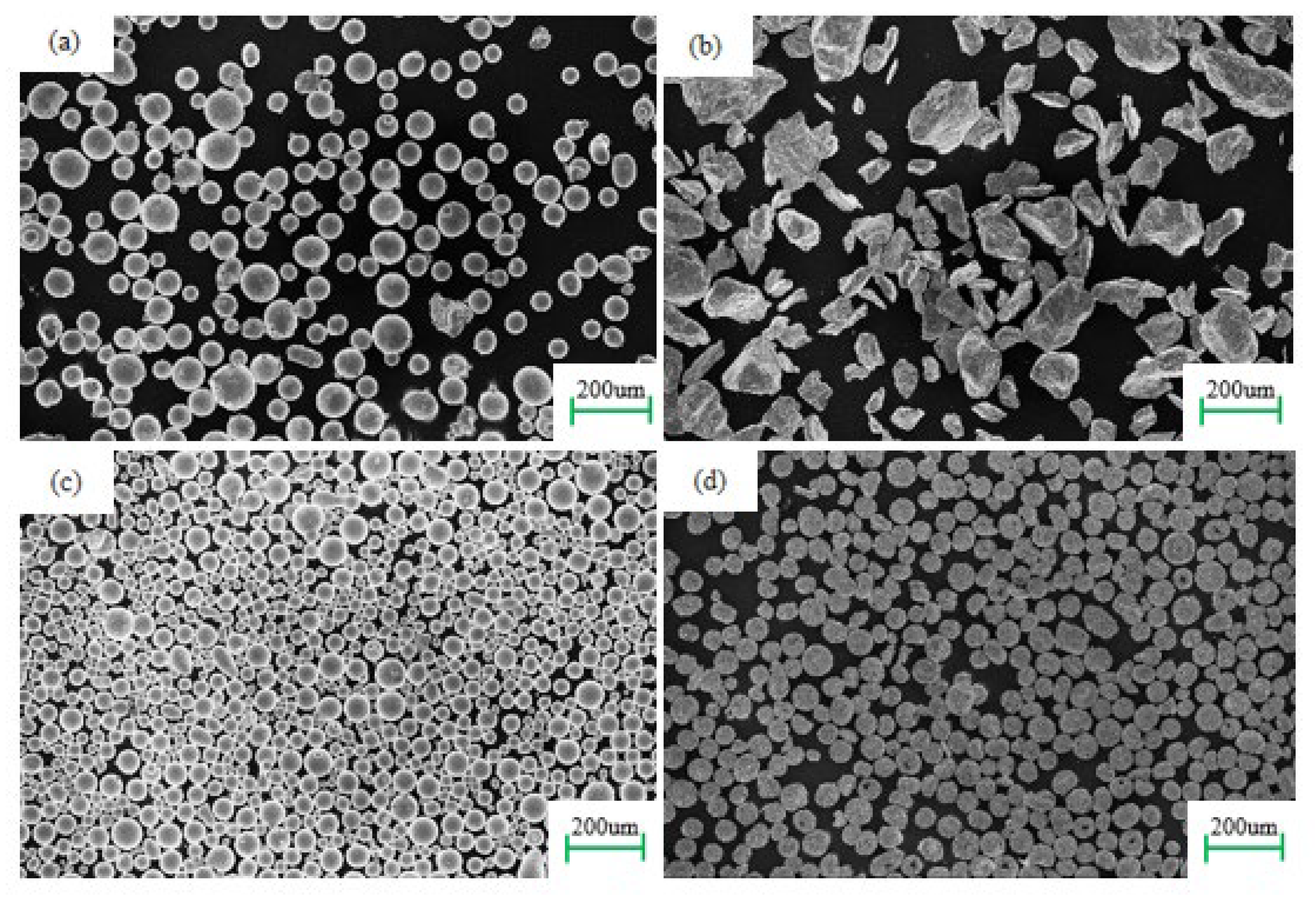
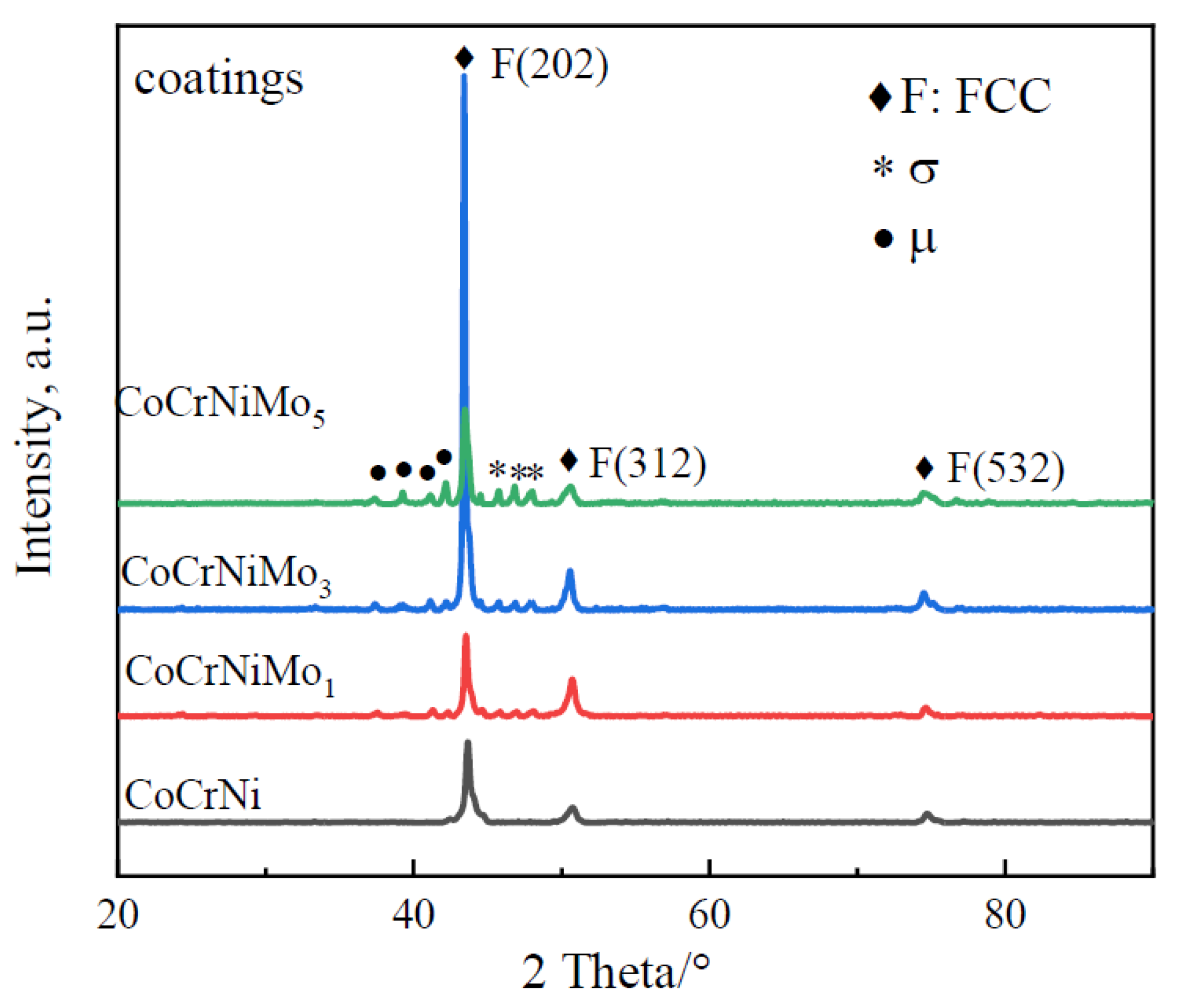
3.1. Morphologies and XRD Analysis of the Mixed Powders

Figure 1 shows the morphologies of as-received Co, Cr, Ni, and Mo powders, respectively. The Co, Ni, and Mo powders have relatively uniform spherical shapes with mean particle sizes of 104.8, 65.9, and 62.0 μm, respectively. The Co, Ni, and Mo powders have better fluidity, while the particle shape of the Cr powder is irregular, and the size distribution is uneven with D25 = 108.3 μm and D50 = 147.4 μm.
To compare with the generated phases in the coatings, the XRD patterns of the as-milled CoCrNiMo powders were tested and the results are shown in Figure 2. The index of XRD peaks suggests that Co, Cr, and Ni largely exist with their elemental crystal structures in all laser cladding powders. The weak diffraction peaks of Mo only present at about 41° and 64° in the XRD patterns of CoCrNiMo1, owing to the low content of Mo (only 1 wt.%). With the increasing content of Mo, its diffraction peak becomes much stronger. Meanwhile, the diffraction peak of Co decreases slightly.

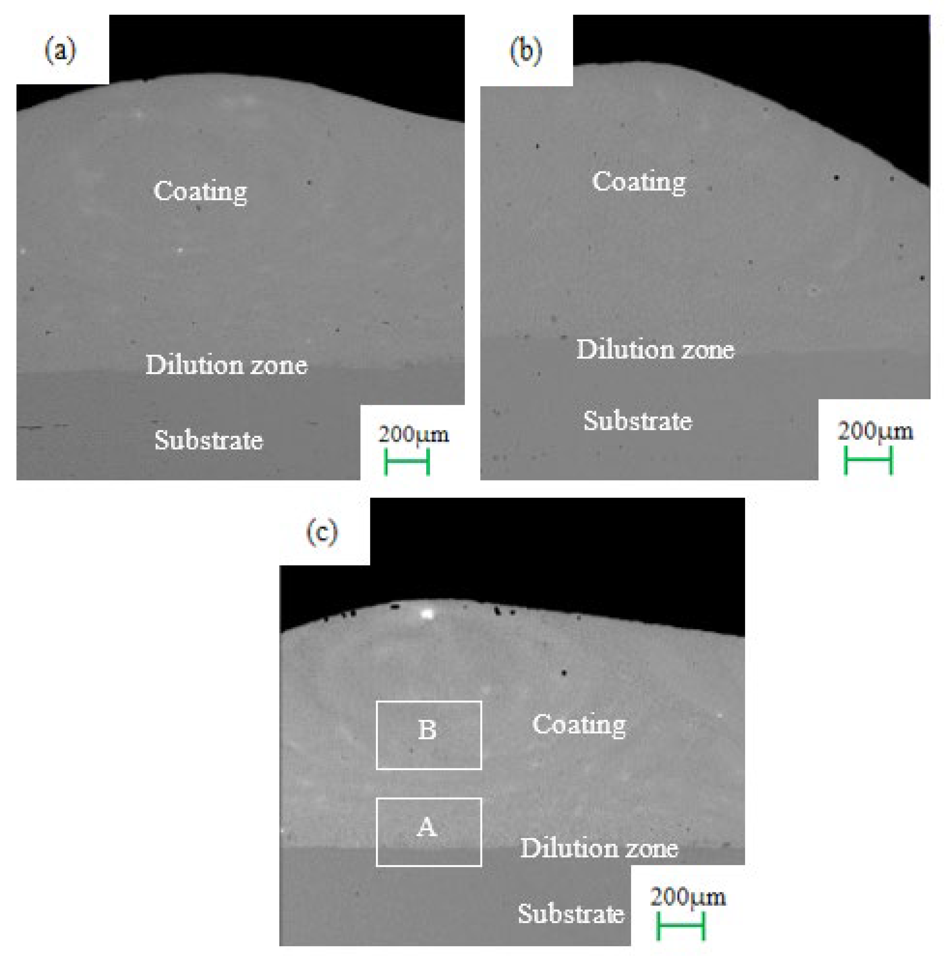
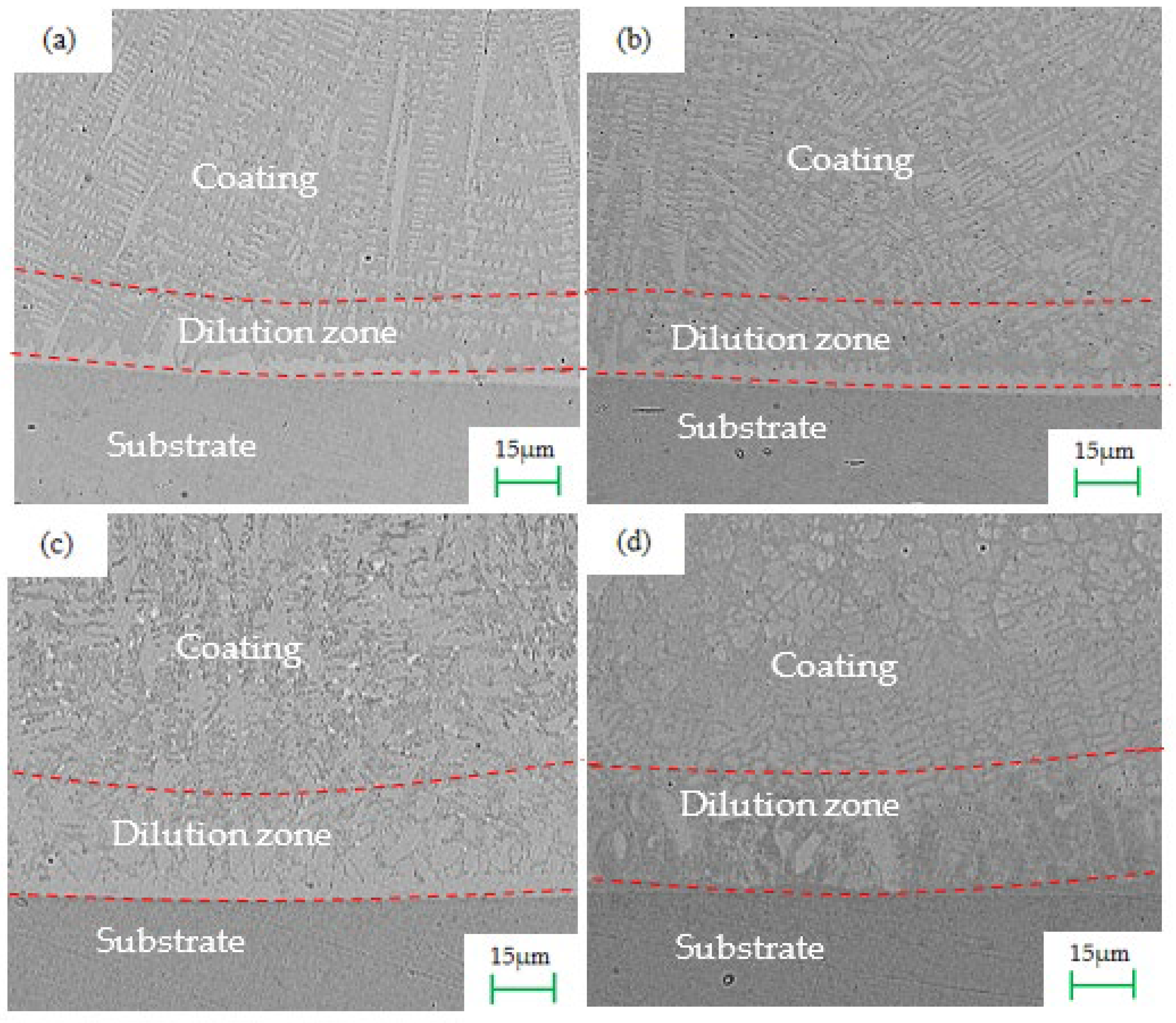
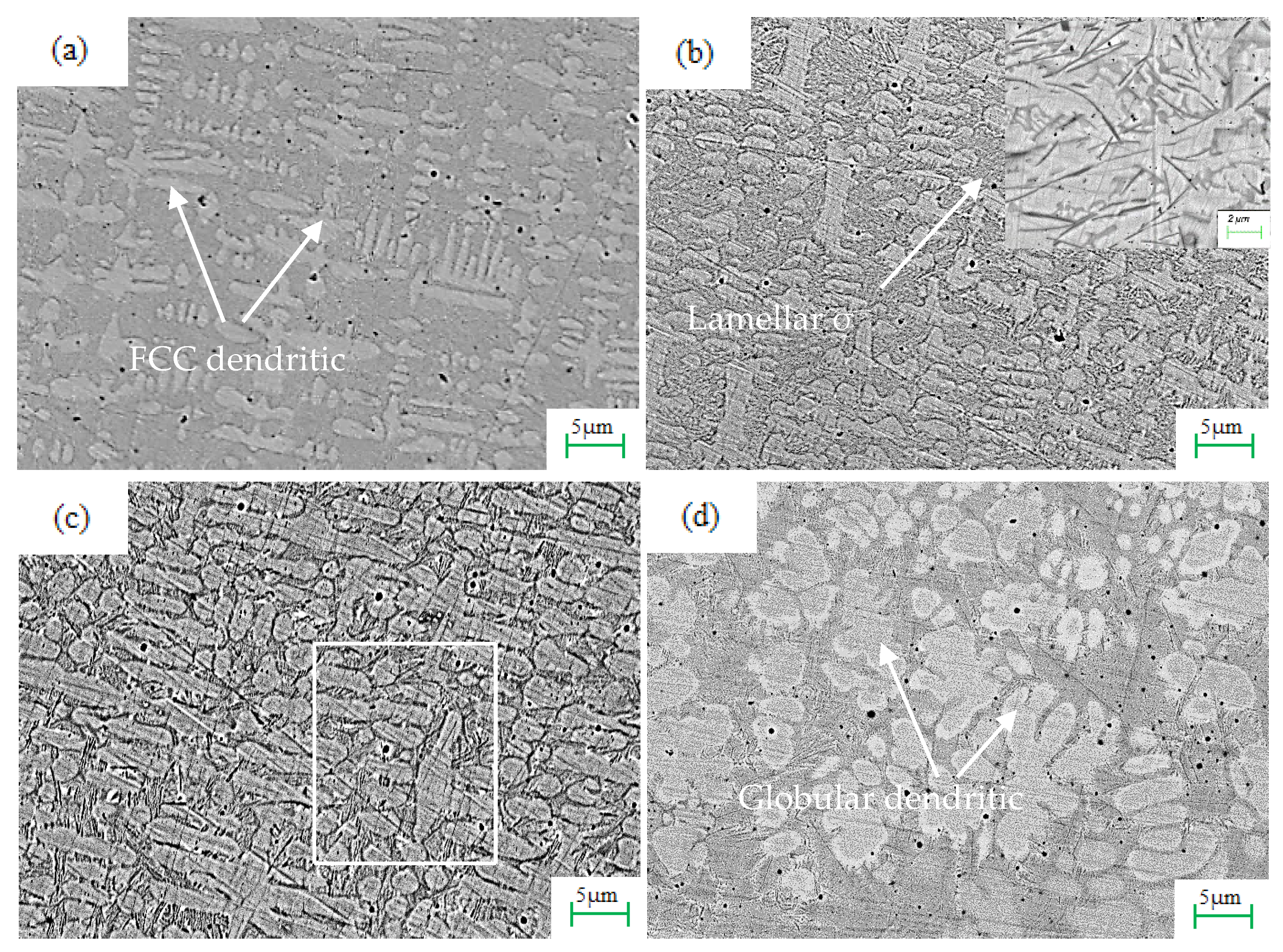
3.2. Morphologiesof the Composites Coatings

XRD spectra of laser cladded CoCrNi coating with Mo from 0 to 5 wt.% is shown in Figure 3. According to the previous reports [22], the CoCrNi ternary alloy formed a single-phase FCC crystal structure. In this work, it is clearly seen that the pure CoCrNi formed a single-phase FCC structure alloy in the coating, in contrast with the powders. Furthermore, the addition of Mo in CoCrNi induces the precipitation of the σ phase, with diffraction peaks between 42° and 50°. It has a lattice parameter of a = 9.170 Å, c = 4.741 Å with its structure close to a tetragonal FeCrMo phase; in situ formation of the μ phase with weak diffraction peaks is also identified on the left side of the XRD pattern for the CoCrNiMo1, CoCrNiMo3, and CoCrNiMo5 coatings [23,24]. The Μ phase has a lattice parameter of a = 4.762 Å, c = 25.617 Å, which has a structure close to a rhombohedral Co7Mo6 phase. From Figure 3, with the increase of Mo concentration, the diffraction peaks of the μ and σ phases gradually become stronger. It can be summarized that the contents of the μ and σ phases were promoted by Mo. With the increase of Mo content, the phase compositions of the samples changed from FCC to FCC + σ + μ.
Figure 4 shows the macrograph of the CoCrNi, CoCrNiMo3, and CoCrNiMo5 samples on the cross section. It can be seen from the figure that the cladding layer has no obvious defects, such as cracks and pores. The highest thickness of the three coating is about 1.02, 1.15, and 0.94 mm respectively. It also can be seen that the macrographs can be roughly divided into three areas, namely the coating zone, the dilution zone near the substrate, and the substrate zone. However, there is no obvious boundary of the heat-affected zone.
Figure 5 presents back-scattered SEM micrographs at the junction of the coatings and the substrate on the cross section, which is zone A in Figure 4c. The dilution rate is also one of the important criteria for judging the quality of the cladding layer, which refers to the ratio of the height of the cladding zone to the sum of the heights of the cladding zone and the dilution zone. The thickness of dilution zone is 15, 18, and 25 μm for CoCrNi, CoCrNiMo3, and CoCrNiMo5, so the dilution rate of the above three samples is about 1.47%, 1.56%, and 2.66%. The low dilution rate indicated that a good metallurgical bonding formed between the coating and substrate.
According to the solidification theory [25], in the process of laser cladding, the growth morphology and the size of crystals are affected by the temperature gradient (GL) and the solidification rate (SR). In the initial stage of cladding, when the laser energy is irradiated on the substrate, the temperature of the substrate rises rapidly and a molten pool is formed on the surface. In addition, due to the composition difference between the substrate and the cladding layer, mutual diffusion occurs, which hinders the growth of the grains, resulting in the rapid nucleation of the grains and the inability to continue to grow. Thus, a layer of fine-grained planar crystals is formed at the bottom, and a clearly visible white bright band is produced, which indicates that the cladding layer formed a good metallurgical bond with the substrate. By contrast, dendrite crystals appear in most parts of the cladding. Closer to the interface zone, the sizes of the grains are relatively coarse and unevenly distributed. The grains closer to the center of the coating are denser and have more uniform sizes. That is because with the increase of the longitudinal direction, since the GL gradually decreases relative to the bottom, the SR gradually becomes larger and the grains grow rapidly along the direction of the decreasing GL, which promotes dendrites to form. It can be seen that the dendrites have a certain angle with the center of the molten pool. This is because the closer the laser energy is to the center, the larger the center line is. GL is larger than other heat dissipation directions. Therefore, the closer to the center of the coating, the denser the grains and the more uniform the size. Laser cladding simultaneously introduces grain nuclei in different directions, resulting in a sparse grain structure.
The morphologies at the middle of the coatings are shown in Figure 5, which is zone B in Figure 4c. Combined with the XRD results, the Mo0 coating is comprised of a simple FCC solid solution, which is due to the effects of the approximately atomic size of the constitutional elements and the lack of any significantly negative or positive mixing enthalpy of atom pairs between each element [23]. The other three coatings with the addition of Mo display dendritic and inter-dendritic grains, which represents typical eutectic microstructure. In supplementation to the XRD result in Figure 3, Figure 5a reveals some blocky precipitations at the grain boundaries. According to the previous reports [22], the lamellar structure embedded between the FCC grains is (Cr, Mo)-rich σ phase, seen in magnification image in the Figure 6b. A similar eutectic microstructure was observed in the CoCrNiMo alloy. With the increase of Mo content, the secondary σ phase appeared within the FCC phase. When the Mo content reached 5%, the microstructure of the CoCrNiMo alloy seemingly transformed into a hypoeutectic microstructure with a globular shape. Kang et al. [26] revealed that dendrites and inter-dendritic structures were formed due to the rapid solidification characteristics of the molten pool. At the early stage of solidification, the cladding layer and substrate solidified rapidly, thus generating dendritic microstructures. Shun et al. [23] believed that the occurrence of formation of the μ phase is because the σ phase is not able to maintain its tetragonal structure due to the large lattice strain created by the presence of excess Mo, which resulted in the transformation of the σ phase into a rhombohedral μ phase.
The CoCrNiMo3 coating was tested using EDS to analyze the distribution of elements. It can be seen from Figure 7 that the cladding layer is mainly composed of elements Co, Cr, Ni, Mo, Fe, and C, of which Fe and C originated from the low-carbon steel substrate. This indicated that the atomic diffusion occurred during the laser cladding process. It can be seen from the EDS that Co, Ni, and Fe mainly exist in dendrites, which is consistent with the XRD and SEM results, while Cr, Mo, Fe, and Cr mainly exist in the inter-dendritic structure, and C mainly exists in the gap between dendrites and inter-dendritic structures. In this study, the principal elements Co, Cr, and Ni have nearly the same atomic sizes (rCo = 0.125 nm, rCr = 0.128 nm, and rNi = 0.124 nm) and the mixing enthalpies of different atom pairs among the three elements are nearly equal to zero [21]. These offer us a path to roughly treat the CoCrNi alloy as a single solvent with FCC structure when blending a minor amount of Mo, which serves as solute into the medium entropy alloy [22]. It can also be found that the structure of dendrites is single-phase without compositional variations, while the small grains located among the inter-dendritic grains are enriched of Cr and Mo and depleted of Co and Ni. They should be the σ and μ phases. Due to the large lattice strain generated by the presence of excess Mo, the σ phase cannot maintain its quadrangular structure. The transformation of the σ phase into the rhombohedral μ phase releases the lattice strain [23].
Some black spots also can be found in all the coatings. Thus, in order to determine the composition, the black spots of the CoCrNiMo1 coating were selected for EDS analysis, and the results are shown in Figure 8. It can be seen from the figure that the black spots are composed of all elements from the alloy coating and substrate, including Co, Cr, Ni, Mo, Fe, and C. This may indicate that the spots are formed by incomplete melting and rapid solidification during the coating process. A study by Adomako et al. [25] found that the higher the scanning speed, the shorter the laser heating/melting time, resulting in an incomplete melting of the powder, which coupled with rapid solidification and resulted in the formation of pores, in consistency with our conclusion.

3.3. Microhardness Analysis of the Coatings

The microhardness distribution from the boundary between the coating and substrate is shown in Figure 9. It can clearly be seen that the microhardness of coatings is much higher than that of the low-carbon steel substrate. It indicates that elements alloying plays a vital role in the enhancement of hardness. The microhardness curves of samples with Mo share a similar stepped distribution trend, which is consistent with the microstructures. However, the hardness of the CoCrNi coating without Mo added is slightly different, and the hardness of the area close to the substrate is significantly improved. This may be because a small amount of Cr element diffuses to the interface between the coating and the substrate under the action of heat, so that the strengthening effect is produced here [25]. When the concentration of Mo reaches to 5%, the hardness of the coating is the highest. The positional hardness peak is found at 0.6 mm from the boundary in the coating, which is 750 ± 87 HV0.1, about three times of the substrate. The reason can be explained by Mo atoms dissolved in the matrix, which can effectively improve the lattice distortion and the hardness of the CoCrNi matrix. On the other hand, the formation of new phases (the σ and μ phase) also contributed to the hardness of alloyed coating [13]. It should be noted that there are differences in the hardness of the substrates between several of the samples that may be caused by the difference in the temperature of the substrates, which is due to the different sequences of laser cladding that are placed on each substrate.

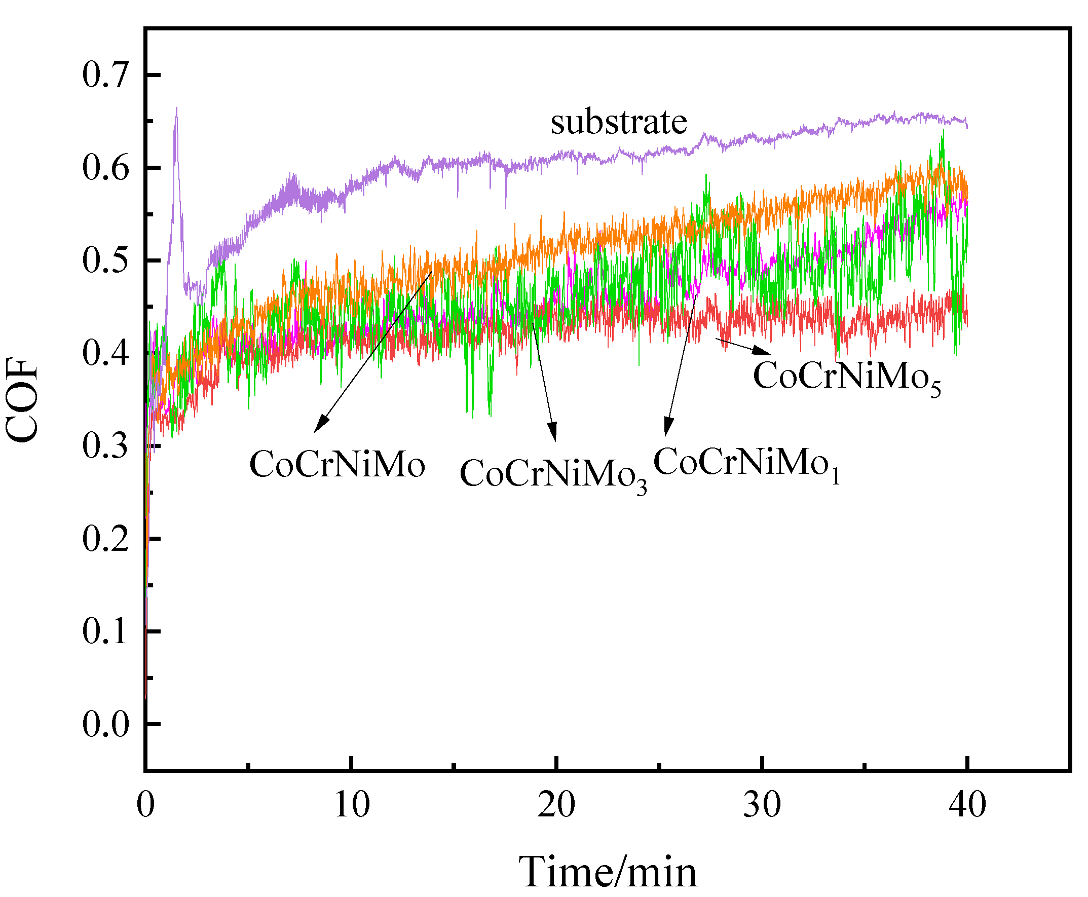
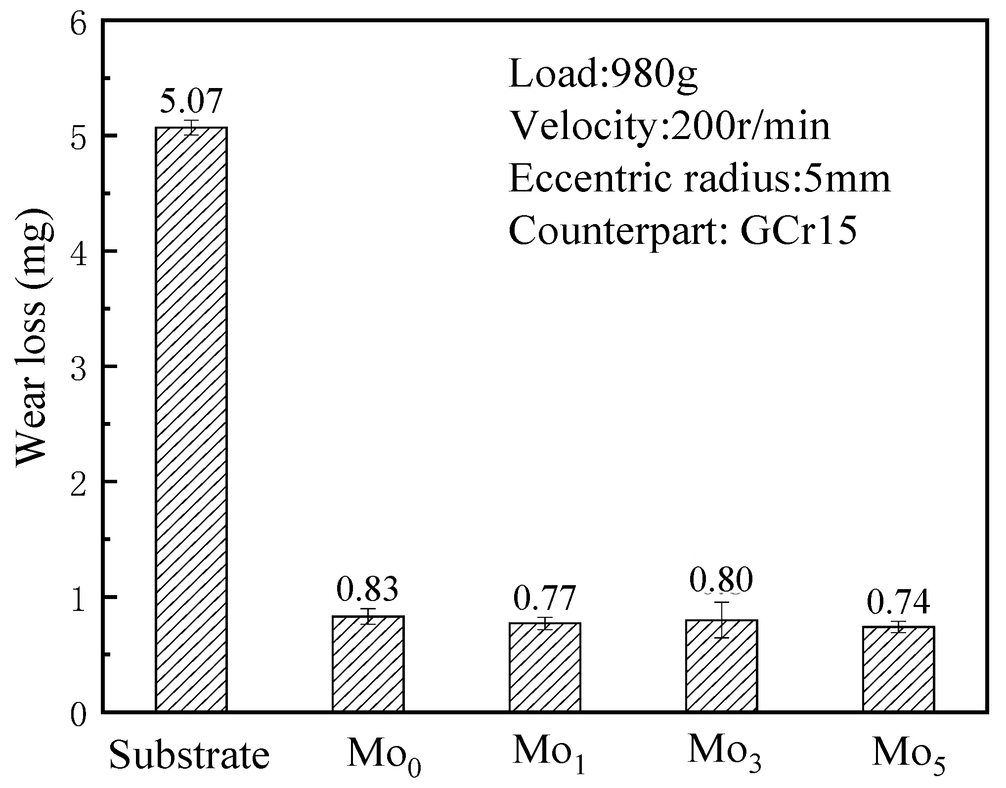
3.4. Friction and Wear Testing Analysis

Friction and wear tests were carried out on the substrate and several laser claddings layers separately for 40 min. The COF curves of CoCrNiMox coatings are shown in Figure 10. It can be seen that the COF between the substrate and the cladding layer is unstable and rises rapidly at the beginning of the test, which is the initial running-in stage. After the surface of the sample is subjected to severe wear, wear scars and grooves appear on the surface and the COF increases rapidly. After 4 min, the surface roughness of the two samples tends to be flat, and the curve runs into a stable period, at which time the COF is relatively stable. The average friction coefficient of the samples after 4 min was calculated, and the average COF of low carbon steel was 0.611. The average COF of the CoCrNi coating was 0.517, which is lower than the substrate. The addition of Mo can significantly decrease the COF value of CoCrNiMo coatings. The COF values of the Mo1, Mo3, and Mo5 samples were 0.473, 0.467 and 0.428, respectively. The obvious decrease of COF value with the addition of Mo can be explained by the improved microhardness, which prevents the penetrating effect of the indenter.
Figure 11 shows the wear loss of samples after the friction experiment. Compared with the wear loss of several coatings, the low carbon steel substrate has the largest value, which was 5.07 mg. The wear loss of the cladding layer decreases slightly with the increase of Mo content, which were 0.81, 0.77, 0.80, and 0.74 mg respectively. Compared to the substrate, the wear loss was reduced by 84.0%, 84.8%, 84.6%, and 85.4% respectively. The coating containing 5 wt.% Mo had the highest hardness and therefore induced a least wear loss, while the samples containing 1% and 3% Mo had almost the same hardness in the stable microstructure, so the wear loss was almost the same. The CoCrNi coating without Mo was relatively not hard, and its wear loss was the largest under the friction of the harder counter-grinding pair GCr15.
To further analyze the wear mechanism, Figure 12 reveals the micrograph of the wear track. Figure 12a–d is a micrograph of the wear width of the four coatings, which shows the average wear widths of CoCrNi, CoCrNiMo1, CoCrNiMo3, and CoCrNiMo5 are 717, 643, 584, and 375 μm, respectively. Commonly, the friction and wear properties of materials are positively correlated with hardness, so the narrowness of the CoCrNiMo5 coating may be due to its high hardness, which enables it to resist external forces well, thus showing better friction and wear performance.
As shown in Figure 12e–h, there are continuous furrows parallel to the friction direction on the surface of the cladding layers. This is because abrasive particles which can enter the friction surface during the friction process interact with a small amount of grinding that falls off during the friction process. Deep plough grooves and spalling craters appear on the surface of CoCrNi coating. This is mainly due to the repeated action of contact stress during the friction process, which leads to the occurrence of sticking phenomenon. The dominated wear mechanisms are adhesive wear and abrasive wear. When the Mo is added in the coatings, the wear surface is dominated by more wear debris and fine furrows, and the size of the wear debris plaques is different, indicating that the wear mechanism is adhesive wear and fatigue wear. Among them, CoCrNiMo5 coating has the smoothest surface after friction and wear, as shown in Figure 12h, with only a few grooves and small furrows, showing a slightly fatigued wear.
In order to further study the wear debris composition of the coating surface after friction and wear, energy dispersive spectroscopy (EDS) analysis was performed on the surface of Mo3 after friction and wear, and an EDS point scan was performed on the wear debris on the surface after friction and wear, as shown in Figure 13. It can be seen from the figure that the wear debris on the friction and wear surface of Mo3 is mainly composed of Co, Cr, and Ni elements. Combined with the XRD pattern of the coating, it is inferred that the granular wear debris is the single-phase FCC ternary compound.

4. Conclusions

In this paper, CoCrNiMox multi-principal alloy coatings were prepared on the surface of low carbon steel by laser cladding technology, and the effects of different concentration of Mo element on the microstructure and properties of the coatings were studied. The following conclusions are drawn:
(1)
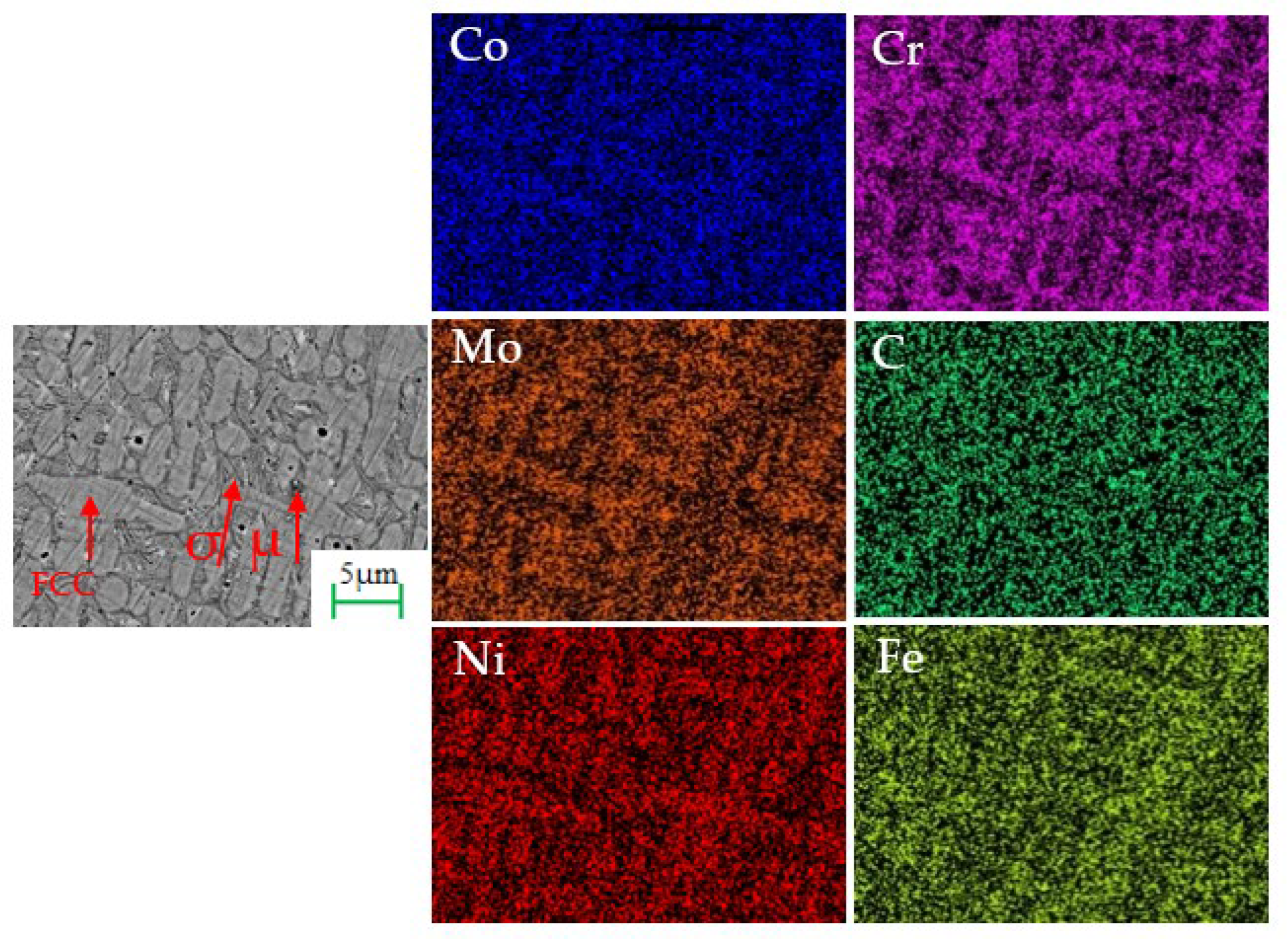
The microstructures of the multi-principal cladding layer of CoCrNiMo with different Mo concentrations are composed of dendrites and inter-dendritic structures. A single-phase face-centered cubic (FCC) structure generated by CoCrNi ternary compound in all the coatings. The inter-dendritic structures are the σ- and μ-phase enriched with Cr and Mo, which originated with additional Mo and exhibited a lamellar structure. With the increase of Mo, the shape of the dendrite changed from rod-like to spherical-like. Meanwhile, the microstructure composition of the samples changed from FCC to FCC + σ + μ.
(2)
With the increase of Mo concentration, the hardness in the coatings increases while the COF decreases, owing to the formation of a hard σ and μ phase. The wear loss of the coating of Mo5 is the smallest, with narrowest wear track. The higher hardness makes the coating more resistant to the plastic deformation of the wear surface. The wear mechanism also changes from adhesive wear and abrasive wear to adhesive wear and fatigue wear.

Author Contributions

Conceptualization, R.L.; writing—original draft preparation, X.D.; investigation, Y.P.; writing—review and editing, R.L.; metrology, T.W. All authors have read and agreed to the published version of the manuscript.

Funding

The presented research results were funded by the Beijing Municipal Education Commission Science and Technology Plan General Project (KM201910009006).

Institutional Review Board Statement

Not applicable.

Informed Consent Statement

Not applicable.

Data Availability Statement

The data presented in this study are available on request from the corresponding author.

Conflicts of Interest

The authors declare no conflict of interest.

References

  1. Dalai, R.; Das, S.; Das, K. Effect of thermo-mechanical processing on the low impact abrasion and low stress sliding wear resistance of austenitic high manganese steels. Wear 2019, 420–421, 176–183. [Google Scholar] [CrossRef]
  2. Chou, C.C.; Lee, S.H. Tribological behavior of nanodiamond-dispersed lubricants on carbon steels and aluminum alloy. Wear 2010, 269, 757–762. [Google Scholar] [CrossRef]
  3. Ding, H.H.; Mu, X.P.; Zhu, Y.; Yang, W.; Xiao, Q.; Wang, W.; Liu, Q.; Guo, J.; Zhou, Z. Effect of laser claddings of Fe-based alloy powder with different concentrations of WS2 on the mechanical and tribological properties of railway wheel. Wear 2022, 488–489, 204174. [Google Scholar] [CrossRef]
  4. Liu, S.S.; Zhang, M.; Zhao, G.L.; Wang, X.H.; Wang, J.F. Microstructure and properties of ceramic particle reinforced FeCoNiCrMnTi high entropy alloy laser cladding coating. Intermetallics 2022, 140, 107402. [Google Scholar] [CrossRef]
  5. Li, Z.L.; Wei, M.M.; Xiao, K.; Bai, Z.; Xue, W.; Dong, C.; Wei, D.; Li, X. Microhardness and wear resistance of Al2O3-TiB2-TiC ceramic coatings on carbon steel fabricated by laser cladding. Ceram. Int. 2019, 45, 115–121. [Google Scholar] [CrossRef]
  6. Duriagina, Z.; Kulyk, V.; Kovbasiuk, T.; Vasyliv, B.; Kostryzhev, A. Synthesis of Functional Surface Layers on Stainless Steels by Laser Alloying. Metals 2021, 2021, 434. [Google Scholar] [CrossRef]
  7. Bartkowski, D.; Bartkowska, A.; Juri, P. Laser cladding process of Fe/WC metal matrix composite coatings on low carbon steel using Yb: YAG disk laser. Opt. Laser Technol. 2021, 136, 106784. [Google Scholar] [CrossRef]
  8. Jiang, G.Y.; Liu, Y.P.; Xie, J.L.; Wang, W.C. Mechanical and Corrosion Resistance of Laser Cladding Ni-Based Alloy of Steel Plate under Variable Defocusing. Opt. Int. J. Light Electron Opt. 2020, 224, 165464. [Google Scholar] [CrossRef]
  9. Huang, C.; Zhang, Y.; Vilar, R.; Shen, J. Dry sliding wear behavior of laser clad TiVCrAlSi high entropy alloy coatings on Ti-6Al-4V substrate. Mater. Des. 2012, 41, 338–343. [Google Scholar] [CrossRef]
  10. Zhao, D.; Yamaguchi, T.; Tusbasa, D.; Wang, W. Fabrication and friction properties of the AlFeCrCo medium-entropy alloy coatings on magnesium alloy. Mater. Des. 2020, 193, 108872. [Google Scholar] [CrossRef]
  11. Huang, S.; Wu, H.; Zhu, H.; Xie, Z. In-situ TiC/Fe0.6MnNi1.4 medium entropy alloy matrix composites with excellent strength-ductility synergy. Ceram. Int. 2021, 47, 26319–26326. [Google Scholar] [CrossRef]
  12. Jiang, Z.; Wei, R.; Wang, W.; Li, M.; Han, Z.; Yuan, S.; Zhang, K.; Chen, C.; Wang, T.; Li, F. Achieving high strength and ductility in Fe50Mn25Ni10Cr15 medium entropy alloy via Al alloying. J. Mater. Sci. Technol. 2022, 100, 20–26. [Google Scholar] [CrossRef]
  13. Zhang, Z.; Zhang, B.; Zhu, S.; Tao, X.; Tian, H.; Wang, Z. Achieving enhanced wear resistance in CoCrNi medium entropy alloy co-alloyed with multi-elements. Mater. Lett. 2022, 313, 131650. [Google Scholar] [CrossRef]
  14. Laplanche, G.; Kostka, A.; Reinhart, C.; Hunfeld, J.; Eggeler, G.; George, E.P. Reasons for the superior mechanical properties of medium-entropy CrCoNi compared to high-entropy CrMnFeCoNi. Acta Mater. 2017, 128, 292–303. [Google Scholar] [CrossRef]
  15. Lee, D.; Agustianingrum, M.P.; Park, N.; Tsuji, N. Synergistic effect by Al addition in improving mechanical performance of CoCrNi medium-entropy alloy. J. Alloy. Compd. 2019, 800, 372–378. [Google Scholar] [CrossRef]
  16. Chang, H.; Zhang, T.W.; Ma, S.G.; Zhao, D.; Xiong, R.L.; Wang, T.; Li, Z.Q.; Wang, Z.H. Novel Si-added CrCoNi medium entropy alloys achieving the breakthrough of strength-ductility trade-off. Mater. Des. 2021, 197, 109202. [Google Scholar] [CrossRef]
  17. Chang, R.; Fang, W.; Bai, X.; Xia, C.; Zhang, X.; Yu, H.; Liu, B.; Yin, F. Effects of tungsten additions on the microstructure and mechanical properties of CoCrNi medium entropy alloys. J. Alloy. Compd. 2019, 790, 732–743. [Google Scholar] [CrossRef]
  18. Shi, Y.; Wang, Y.D.; Li, S.; Li, R.; Wang, Y. Mechanical behavior in boron-microalloyed CoCrNi medium-entropy alloy studied by in situ high-energy X-ray diffraction. Mater. Sci. Eng. A 2020, 788, 139600. [Google Scholar] [CrossRef]
  19. Wang, J.; Yang, H.; Huang, H.; Ruan, J.; Ji, S. In-situ Mo nanoparticles strengthened CoCrNi medium entropy alloy. J. Alloy. Compd. 2019, 798, 576–586. [Google Scholar] [CrossRef]
  20. Chang, R.; Fang, W.; Yan, J.; Yu, H.; Bai, X.; Li, J.; Wang, S.; Zheng, S.; Yin, F. Microstructure and mechanical properties of CoCrNi-Mo medium entropy alloys: Experiments and first-principle calculations. J. Mater. Sci. Technol. 2020, 62, 25–33. [Google Scholar] [CrossRef]
  21. Li, N.; Chen, W.T.; He, J.Y.; Gu, J.; Wang, Z.; Li, Y.; Song, M. Dynamic deformation behavior and microstructure evolution of CoCrNiMox medium entropy alloys. Mater. Sci. Eng. A 2021, 827, 142048. [Google Scholar] [CrossRef]
  22. Chung, D.H.; Liu, X.D.; Yang, Y. Fracture of sigma phase containing Co-Cr-Ni-Mo medium entropy alloys. J. Alloy. Compd. 2020, 846, 156189. [Google Scholar] [CrossRef]
  23. Shun, T.T.; Chang, L.Y.; Shiu, M.H. Microstructure and mechanical properties of multi-principal component CoCrFeNiMo x alloys. Mater. Charact. 2012, 70, 63–67. [Google Scholar] [CrossRef]
  24. Ambrozini, B.; Guastaldi, A.C.; Herculano, R.D.; Miranda, M.C.; Jafelicci, M., Jr. Sol-gel based calcium phosphates coating deposited on Co-Cr-Ni-Mo alloys modified by laser beam irradiation for cardiovascular devices. Mater. Today Proc. 2019, 14, 663–670. [Google Scholar] [CrossRef]
  25. Adomako, N.K.; Noh, S.; Oh, C.S.; Yang, S.; Kim, J.H. Laser deposition additive manufacturing of 17-4PH stainless steel on Ti-6Al-4V using V interlayer. Mater. Res. Lett. 2019, 7, 259–266. [Google Scholar] [CrossRef]
  26. Qi, K.; Yang, Y.; Liang, W.; Jin, K.; Xiong, L. Influence of the anomalous elastic modulus on the crack sensitivity and wear properties of laser cladding under the effects of a magnetic field and Cr addition. Surf. Coat. Technol. 2021, 423, 127575. [Google Scholar] [CrossRef]
Figure 1. Morphologies of powders used in the coatings (a) Co; (b) Cr; (c) Ni; and (d) Mo.
Crystals 12 01229 g001
Figure 2. XRD patterns of CoCrNiMox powders after ball milling.
Crystals 12 01229 g002
Figure 3. XRD spectras of CoCrNiMox coating after laser cladding.
Crystals 12 01229 g003
Figure 4. The macrograph of (a) CoCrNi, (b) CoCrNiMo3, and (c) CoCrNiMo5 coating.
Crystals 12 01229 g004
Figure 5. Micrographs at the junction between the coatings and substrate on the cross section. (a) CoCrNi, (b) CoCrNiMo1, (c) CoCrNiMo3, and (d) CoCrNiMo5.
Crystals 12 01229 g005
Figure 6. Morphologies at the middle of coatings on the cross section. (a) CoCrNi, (b) CoCrNiMo1, (c) CoCrNiMo3 and (d) CoCrNiMo5.
Crystals 12 01229 g006
Figure 7. EDS mapping of CoCrNiMo3 composite coating.
Crystals 12 01229 g007
Figure 8. EDS point scanning spectrum of black spots in CoCrNiMo1 composite coating.
Crystals 12 01229 g008
Figure 9. Microhardness curves from the boundary between substrate and coating.
Crystals 12 01229 g009
Figure 10. Typical COF evolution of CoCrNiMox with sliding time.
Crystals 12 01229 g010
Figure 11. Wear loss of substrate and the laser cladding coatings.
Crystals 12 01229 g011
Figure 12. Morphology of wear track of (a,e) CoCrNi, (b,f) CoCrNiMo1, (c,g) CoCrNiMo3 and (d,h) CoCrNiMo5.
Crystals 12 01229 g012
Figure 13. EDS point scanning spectrum of Mo3 composite coating after friction wear.
Crystals 12 01229 g013
Table 1. Compositions of CoCrNiMox alloy coating.
Sample No.CompositeWeight Ratio (%)Molar Ratio (%)
CoCrNiMoCoCrNiMo
Mo0CoCrNiMo0353134033.633.732.70
Mo1CoCrNiMo1353034133.432.632.61.4
Mo3CoCrNiMo3343033332.232.231.44.2
Mo5CoCrNiMo5332933531.030.931.17.0
Publisher’s Note: MDPI stays neutral with regard to jurisdictional claims in published maps and institutional affiliations.

