Abstract
The effect of plaque deposition (atherosclerosis) on blood flow behaviour is investigated via computational fluid dynamics and structural mechanics simulations. To mitigate the narrowing of coronary artery atherosclerosis (stenosis), the computational modelling of auxetic and non-auxetic stents was performed in this study to minimise or even avoid these deposition agents in the future. Computational modelling was performed in unrestricted (open) conditions and restricted (in an artery) conditions. Finally, stent designs were produced by additive manufacturing, and mechanical testing of the stents was undertaken. Auxetic stent 1 and auxetic stent 2 exhibit very little foreshortening and radial recoil in unrestricted deployment conditions compared to non-auxetic stent 3. However, stent 2 shows structural instability (strut failure) during unrestricted deployment conditions. For the restricted deployment condition, stent 1 shows a higher radial recoil compared to stent 3. In the tensile test simulations, short elongation for stent 1 due to strut failure is demonstrated, whereas no structural instability is noticed for stent 2 and stent 3 until 0.5 (mm/mm) strain. The as-built samples show a significant thickening of the struts of the stents resulting in short elongations during tensile testing compared to the simulations (stent 2 and stent 3). A modelling framework for the stent deployment system that enables the selection of appropriate stent designs before in vivo testing is required. This leads to the acceleration of the development process and a reduction in time, resulting in less material wastage. The modelling framework shall be useful for doctors designing patient-specific stents.
1. Introduction
Cardiovascular disease is a common disease that is responsible for more deaths in the USA than all cancers combined [1]. Coronary artery disease, which is a common type of cardiovascular disease, kills 610,000 people and is the leading reason for mortality in the USA [2]. Globally, there are 17.8 million deaths due to coronary artery disease, and it is the third leading reason for mortality [3,4,5,6]. According to the world health statistics published by the World Health Organization (WHO), deaths from cardiovascular diseases are expected to rise from 17 million in 2008 to 25 million in 2030 [7]. The most obvious solution to heart failure is the replacement of the heart. However, heart transplantation requires expensive and high-risk surgery. In the USA, 4000 people are in urgent need of heart transplantation, while only 2500 donate their hearts each year [8]. This requires a reduction in the risk of cardiovascular disease.
The most common cause of cardiovascular disease is atherosclerosis (plaque formation on the coronary artery wall) [9,10]. The widely used treatment for atherosclerosis is the deployment of stents. Most common stents are made from bioresorbable polymers that support the artery during deployment and healing [11,12]. After the healing process is complete, the stent dissolves, resulting in the reversion of the coronary artery to its original healthy condition [13]. Thus, to cure atherosclerosis, it is mandatory to study the successful deployment of a stent in the coronary artery. Since the margin of error in stent deployment is very small, finite element method (FEM) simulation is an effective tool for testing a stent deployment system.
FEM simulation of balloon-expansion-based stent deployment systems is being investigated by various researchers [14,15,16,17,18,19,20,21,22,23]. In these studies, the deployment of two stent deployment systems is simulated using the inflation of a sophisticated balloon configuration. A limitation of these studies is that the stent and balloon geometries are sketched and not based on μ-CT images. Also, the effect of blood flow and damping on the stent is not considered. An idealised elastic model is used for the balloon material; however, in practice, a folded balloon configuration is accompanied by a catheter shaft. The complex mechanical properties of human tissues modelled using the isotropic homogeneous constitutive material model for artery and plaque is another deficiency with the model.
A detailed review of recent advances in stent development was published by Khalaj et al. [24]. Most of the stents studied exhibit non-auxetic behaviour. An important feature of the successful deployment of non-auxetic stents in the artery is the bridge design between the expanding rings of the stents [19]. A proper design of the connecting bridge between the rings can lead to an increase in expansion capability. Zu et al. [25] addressed polylactic acid stents with a negative Poisson’s ratio structure. However, the deployment of the negative Poisson’s ratio auxetic stent was neglected in this research [25]. Chen et al. [26] investigated the delamination of coating on magnesium alloy stents. The study was based on FEM simulations and predicted the delamination of coatings on the stents as well as stress concentrations during stent deployment. Ang et al. [23] processed stents with nanosized BaSO4/PLLA composites and performed FEM simulations to prove the validity of the stent design with improved mechanical properties at a lower strut thickness and higher structural stability. Since the manufacturing method of the stents is an important aspect, new methods are focused on. Recently, due to the small size and complicated design, additive manufacturing (AM) such as fused deposition modelling (FDM), stereolithography (SL), selective laser sintering (SLS), and laser powder bed fusion (LPBF) are assumed to be the most suitable methods for stent manufacturing [27]. The first three processes are used for the manufacture of polymer-based drug-eluting stents, while the last process is used to process metallic stents. Additive manufacturing also minimises material wastage compared to other stent manufacturing methods such as microtube forming and laser micromachining. The most common alloys for manufacturing metallic stents are cobalt–chromium alloys [28], stainless steel, and nitinol [29,30,31,32]. Demir et al. [28] applied LPBF to produce stents from cobalt–chromium alloys with high geometrical accuracy depending on the laser scanning strategy. An increase in laser power and pulse duration reduced the surface roughness and increased the strut dimensions. Fully dense, crack-free nitinol stents produced by LPBF are also reported in the literature [33]. A lower laser power results in more accurate strut dimensions. Lower laser power also leads to less loss of Ni during manufacturing, leading to a lower austenite finish temperature with higher geometrical accuracy of the stents. In another study on microlaser powder bed fusion (μ-LPBF), nitinol stents with a minimum component size of ≈52 μm and low surface roughness (less than 2 μm) were produced. The stents exhibit a compressive ductility of 50% without mechanical failure and a shape recovery of 98% upon heating. Ti6Al4V alloy-based auxetic structures with a hybrid Poisson’s ratio manufactured by LPBF present very high flexural stiffness (140 MN/mm2) [34]. The microstructure showed fine acicular α′/α plates in the as-built condition due to the very high cooling rates during LPBF.
The elastic modulus of the metastable Ti alloy is in the range of 71.7–79.1 GPa. In the current investigation, the elastic modulus of the stent material is taken as 44 GPa, which is lower than the elastic modulus of Ti alloy or NiTi alloy. In the previous literature, nitinol (Ni-Ti), stainless steel (316 L SS), cobalt–chromium (Co-Cr) alloy, tantalum (Ta), pure iron (Fe), platinum–iridium (Pt-Ir) alloy, and magnesium (Mg) alloys were used for manufacturing stents [35]. Pure Fe and Mg-based alloys are used for the manufacture of coronary stents [36]. Recently, 316 L stainless steel, which has a high Young’s modulus (190 GPa), has been used as a stent that is deployed by balloon expansion, whereas NiTi alloy with a low relative modulus (75–83 GPa) has been used for self-expanded stents [37]. Both 316 L stainless steel and NiTi alloy contain Ni, which is reported to trigger an autoimmune response and inflammation [38]. NiTi alloy also has inadequate magnetic resonance imagining (MRI) compatibility, which creates problems in diagnosis. Other biomedical alloys such as CoCr alloys have a high magnetic susceptibility (1370 × 10−6 cm3/gm [39]) which is unsuitable for MRI diagnosis performed during surgeries. Ti alloys are suitable candidates for metallic stents due to lower magnetic susceptibility (180 × 10−6 cm3/gm [40]), corrosion resistance, and biocompatibility [41]. In this regard, metastable beta-titanium alloys such as Ti-Ta and Ti-Nb alloys have good haemocompatibility and good mechanical properties. Thus, in the current investigation, stents are chosen to be made of metastable beta-titanium alloy.
Currently, there are no studies comparing the effect of auxetic and non-auxetic stent designs on stent deployment. A modelling framework for the stent deployment system is required as it helps in selecting appropriate stent designs from a variety of possible stent designs before in vivo testing or animal experiments. FEM-based virtual testing of stents is proven to be helpful for stents whose performance is difficult to evaluate by in vivo testing [20]. This also accelerates the development process and time, resulting in less wastage of materials and other resources. In addition, the modelling framework will help cardiologists design patient-specific stents before deployment and evaluate the stents’ structural performance. Hence, the research addresses three objectives: (1) investigation of the effect of atherosclerosis on the blood flow dynamics through the artery wall via FEM simulations; (2) examination of the stent deployment mechanisms of auxetic and non-auxetic stents by FEM simulations; and (3) additive fabrication of the auxetic and non-auxetic stents and evaluation of their mechanical properties.
2. Computational Procedure
2.1. Simulation of Blood Flow through the Artery
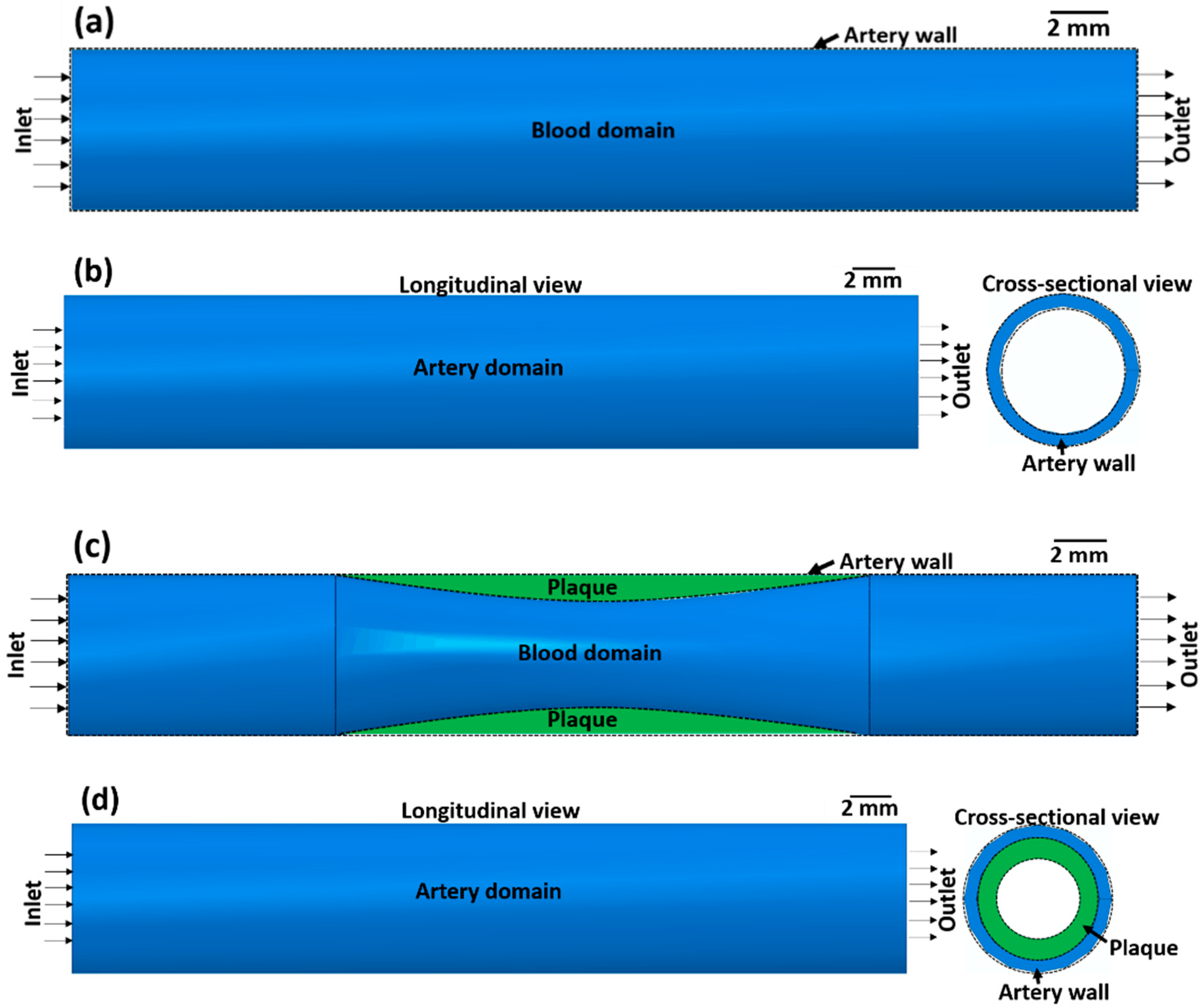
The effect of atherosclerosis on the blood flow through the artery was simulated by applying computational fluid dynamics (CFD) using ABAQUS 6.14-2. Here, a co-simulation approach is adopted in which CFD simulation of blood flow and structural mechanics simulation of the arterial wall is run in parallel. This approach is used to calculate the blood flow velocity in the artery and the stress on the arterial wall. In the co-simulation, the calculated properties from the CFD model are exchanged with the structural mechanics model and vice versa. Co-simulation is performed for two cases, namely (1) an artery without atherosclerosis and (2) an artery with atherosclerosis, to compare the effects of stenosis on blood flow. The co-simulation framework consists of a blood domain model and an artery domain model as presented in Figure 1.

Figure 1.
(a,c) Blood domain and (b,d) artery domain showing the different components of the artery (a,b) without atherosclerosis and (c,d) with atherosclerosis (green colour).
2.1.1. CFD Model of Blood Flow
The blood domain without atherosclerosis is visualised by a 3D cylindrical volume (Figure 1a) with dimensions according to Table 1. For the blood domain with atherosclerosis (Figure 1c), a semi-elliptical region with a length of 10.0 mm and a thickness of 0.5 mm is removed from the 3D cylindrical volume with the physical and fluid properties of the blood domain presented in Table 1. Although there is a significant deviation in the artery blood flow velocity reported in the literature [42,43,44], a nominal blood flow velocity of 50 mm s−1 is assumed based on Ref. [45]. In this investigation, it is assumed that blood is an incompressible Newtonian fluid and the output pressure at the outlet of the artery is 0 Pa. The outer surface of the blood domain in contact with the inner surface of the arterial wall domain is assigned a fluid structure co-simulation boundary interaction condition. To mesh the blood domain, 0.3 mm hexahedral elements are employed. Based on [46], a Spalart–Allmaras turbulence model is assigned to the blood flow in the artery.

Table 1.
Physical and fluid properties of blood and artery wall according to Refs. [47,48].
2.1.2. Structural Mechanics Model of the Artery Wall
The arterial wall domain without atherosclerosis is presented in Figure 1b as a hollow 3D cylindrical volume with the dimensions presented in Table 1. The artery domain with atherosclerosis is visualised as a semi-elliptical region with a length of 10.0 mm and a thickness of 0.5 mm joined to the hollow 3D cylindrical volume. Due to the nonlinear nature and lot of contacting surface pairs, the dynamic implicit solver was used in ABAQUS 6.14-2 to run the simulations. The artery wall and the plaque are considered elastic materials. The end surface of the artery wall is assigned a pinned boundary condition. To mesh the artery wall domain with C3D8 elements, 0.4 mm size hexahedral elements are used. A similar type of element was used in the FEM model in a previous study [20].
2.2. Modelling of Stent Deployment System
The stent deployment system within the stenosed artery consists of different components: (1) stent, (2) angioplasty balloon, and (3) artery with atherosclerosis. In the next sections, each of the different aspects (physical properties of different components, material models, two variants of the stent deployment system, loading and boundary conditions, meshing criteria) of the stent deployment system are described in detail.
2.2.1. Components of the Stent Deployment System
The stent is the main component in the coronary angioplasty procedure responsible for the local expansion of the artery. For the modelling of the stent deployment system, the computer-aided design (CAD) of stents is applied. Three available stent designs from the literature were selected from the open-source CAD library GrabCAD [49]. Stent 1 and stent 2 possess auxetic designs, while stent 3 has a non-auxetic design. Stent 3 is already manufactured by Johnson & Johnson, Warren, NJ, USA [14]. The CAD models of the stents were previously published in Refs. [14,16,21,22,50]; however, in the previous literature, computational modelling and additive manufacturing of the stents were not performed or correlated with each other.
The CAD models of the stents were exported to ABAQUS CAE 2017 in STEP file format and modified after their import to ABAQUS CAE 2017. Table 2 summarises the physical properties of the imported CAD models of the stents (in deflated condition). Here, the FEM simulation of the balloon expansion of the stents undertaken to compare the deformation behaviours of different stent designs. The FEM simulation is performed for two different stent deployment models: unrestricted deployment (in vitro, artery exclusion) and restricted deployment (in vivo, artery inclusion).
Table 2.
Physical properties of stents in the deflated condition.
A balloon which is used to expand the stent to fit into the artery is another important component of the stent deployment system. The CAD modelling of the balloon is undertaken via a 2D cylindrical thin surface. As the inner and outer diameters of the balloons are different, the dimensions of the balloons are also different (Table 3).
Table 3.
Physical properties of the balloon in the deflated, inflated, and recoiled conditions.
The third component of the stent deployment system is the artery with atherosclerosis. Being a biological system, the artery is a complex system. As detailed in [21], the artery has three separate layers: intima, media, and adventitia. The intima is the inner layer of the artery, the media is the middle layer, and the adventitia is the outermost layer. For simplicity, the CAD modelling of the complex artery is accomplished using 3D-deformable cylinders with hyper-elastic material properties. The thickness of each layer of the artery is 0.1 mm. The plaque is modelled with a semi-elliptical shape causing a 35% reduction in blood flow volume. All relevant physical properties of the artery layers are presented in Table 4.
Table 4.
Physical properties of artery layers.
Material Models
Metallic stents are usually made from biomedical-grade 316 L stainless steel, titanium alloys (Ti-6Al-4V, Ti-6Al-7Nb, or Ti-24Nb-4Zr-8Sn (Ti2448)), or nitinol alloys. Here, the stent is assigned the mechanical properties of biomedical metastable β-titanium alloy Ti2448 [52], which are presented in Table 5. A metastable β-titanium alloy is selected for stent manufacturing due to corrosion resistance, good biocompatibility, and non-magnetic nature [53,54]. The presence of the metastable β phase and ω nanoparticles leads to high hardness and compressive strength. So, this alloy can be used to produce thin struts-based stents [53]. In this regard, other metastable β-titanium alloys such as Ti-Ta-Hf-Zr alloys have been used before for the manufacture of stents [53]. Previous studies [20,55] have reported that accurate modelling of the balloon is essential for accurate modelling of the stent deployment system. Since the balloon is made from polyethylene terephthalate or nylon, it is modelled with an isotropic linear elastic material behaviour [21] with the properties summarised in Table 5.
Table 5.
Mechanical properties of stent and balloon.
Being biological materials, all three layers of the artery are modelled with the 3rd-order Ogden hyper-elastic model. The parameters used in the Ogden model for the three layers of the artery are reported in [16] and presented in Table 6. These material parameters are determined by the uniaxial tensile test on artery tissue samples of humans [56]. In [16], the mechanical behaviour of the plaque is described by a 1st-order Ogden hyper-elastic model, so here the data from previous literature are transferred to the simulations.
Table 6.
Hyper-elastic Ogden model parameters for the mechanical behaviour of artery layers and plaque [16].
Equation Solver Characteristics
A general static analysis procedure was chosen to account for the large nonlinear deformation behaviour (nlgeom). An asymmetric matrix storage method is used in the equation solver to address the complicated stent design geometries, elastic and elastoplastic material models, balloon–stent contact behaviour, and complex loading history used for numerical analysis.
Unrestricted Stent Deployment System
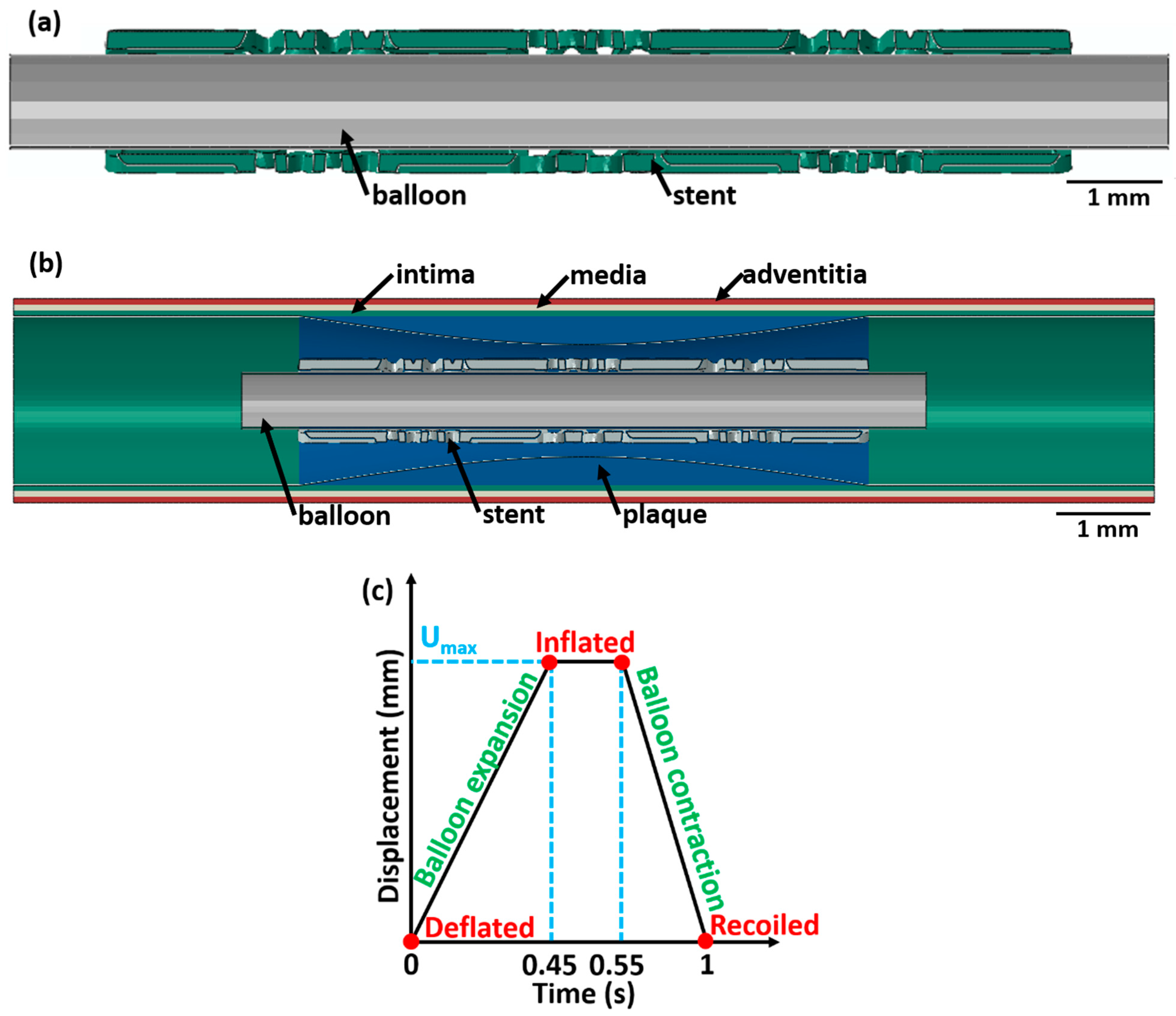
The 3D CAD model of the unrestricted stent 3 deployment system as shown in Figure 2a (as an example) includes two instances: the balloon and stent 3. The dimensions of stent 3 and the balloon are described in Table 1 and Table 2, respectively. To consider the displacement-induced load transfer between the balloon and stent 3, a surface-to-surface contact interaction criteria between the balloon’s outer surface and the stent’s inner surface is introduced in the FEM model. A friction model with a coefficient of 0.2 is assumed between contact surfaces as reported in previous literature [16,57]. A self-contacting contact mechanics is not incorporated in the FEM model as the stent parts do not touch each other in the inflated state. However, a previous study [58] found that the results of the computational models did not differ significantly between a balloon–stent system with friction and a balloon–stent system without friction.
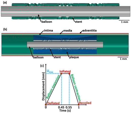
Figure 2.
A longitudinal cross-sectional image showing the different components (with different colours) of the stent 3 deployment system in the deflated condition for (a) unrestricted stent deployment, (b) restricted stent deployment, and (c) variation in balloon displacement amplitude with time. The CAD designs of the auxetic and non-auxetic stent are from literature [14,16,21,22,50].
Restricted Stent Deployment System
The 3D CAD model of the restricted stent 3 deployment system is presented in Figure 2b. The system consists of three instances: balloon, stent, and artery with the dimensions stated in Table 1, Table 2, and Table 3, respectively. The interaction between different contacting surfaces is modelled by surface-to-surface contact criteria with contact friction of 0.2 as reported in the literature [16,57]. Surface-to-surface contact criteria allow effective transfer of the displacement load from the expanding balloon to the stent and the arterial layers.
Loading and Boundary Conditions
For load application, a ρφz-cylindrical coordinate system is introduced in the model. The ρ-axis is the radial direction of the balloon–stent assembly, the φ-axis is along the circumferential direction, and the z-axis is along the longitudinal axis of the balloon–stent model. The origin of the cylindrical coordinate system is fixed by a tie constraint to secure the balloon–stent assembly. For the unrestricted stent deployment system, a radial displacement of 1.5 mm (balloon 1), 2.0 mm (balloon 2), and 1.5 mm (balloon 3) is applied. For the restricted stent deployment system, a radial displacement of 0.65 mm (balloon 1), 0.8 mm (balloon 2), and 0.75 mm (balloon 3) is applied.
For all stent designs, the variation in the balloon displacement amplitude with time is displayed in Figure 2c. The radial displacement on the balloon is applied for 1 s in three stages and increases linearly from 0 s to 0.45 s, is constant between 0.45 s and 0.55 s, and decreases linearly from 0.55 s to 1 s. This radial displacement is chosen based on [20]. At t = 0 s, the balloon is in the deflated state; between t = 0.45 s and 0.55 s, the balloon is in an inflated state; and at t = 1 s, the balloon is in the recoiled state. Using a similar analogy, at t = 0 s, the stent is in the deflated state; from t = 0.45 s to 0.55 s, the stent is in an inflated state; and at t = 1 s, the stent is in the recoiled state. The following assumptions are made: (1) the effect of blood pressure on the balloon, stent, and artery is neglected; (2) the tri-folded initial state of the balloon in the deflated state is disregarded; and (3) a cylindrical shape of the balloon is considered. Similar assumptions were made in a previous investigation and did not affect the result [20].
Meshing Criteria
Since the thickness of the balloon is very small compared to the other two dimensions, surface elements are added to mesh the balloon. The balloon is meshed with SFM3D8 8-node quadrilateral surface elements with a 0.2 mm mesh size. The stent is meshed using C3D10 10-node tetrahedral volume elements with a mesh size of 0.1 mm, whereas the artery is meshed with a C3D20 20-node hexahedral volume element with a mesh size of 0.2 mm. For the unrestricted and restricted stent deployment system, the same mesh size is applied for all components. Thus, the results generated in this investigation do not depend on the mesh size difference of the components between two different sub-models. Due to the high mesh density (fine mesh size) of all components in the stent deployment system model, a mesh convergence study is not undertaken.
Output Structural Parameters
The performance of the different stent designs after the application of the displacement amplitude scheme is evaluated concerning four parameters [20]:
Radial recoil is the amount of elastic recovery of the stent after the balloon displacement load is removed.
Longitudinal retraction is the change in stent length after the inflated state of the stent is achieved. This is an important parameter as an excessive longitudinal retraction of the stent may result in the shearing (injury) of the arterial wall.
The change in stent length in the recoiled state compared to the inflated state is known as foreshortening. A higher foreshortening (large decrease in stent length) results in injury to the arterial wall after the balloon displacement load is removed.
Dog-boning is the increase in stent diameter at the ends of the stent compared to the stent centre owing to non-uniform stent expansion (due to stent design) [21]. Excessive dog-boning of the stent may lead to damage to the artery walls by increasing the stress on the arterial wall in a narrow area.
Excessive thinning of the struts in the stent in the inflated state (due to balloon expansion) is an additional criterion for the damage assessment of the stent. During simulation, each of the struts is carefully observed to reveal excessive thinning of the stent. Excessive thinning can lead to structural failure during deployment. Similar damage assessment criteria are also used in Ref. [20], where intact refers to no strut failure and damaged refers to initial strut failure.
Limitations of the FEM Simulation
FEM simulations have many limitations and drawbacks in terms of the reliability and accuracy of results. Some of the limitations of the FEM simulations are as follows:
- (1)
- The result of the FEM analysis depends on the mesh quality. Poor mesh quality leads to an erroneous result. Also, the time required to solve the stent expansion problem increases as the mesh becomes finer and finer.
- (2)
- If the stent geometry is complex, then FEM simulations are computationally more expensive compared to other numerical methods.
- (3)
- FEM analysis gives approximate solutions for the proposed stent expansion problem. The error is minimised over the whole stent so that we obtain correct solutions only at the nodes.
2.3. Tensile Test Simulations
Tensile test simulations of the stents were performed in ABAQUS CAE 2017. The stent sections and grip sections are assigned the material properties of the additively manufactured (LPBF-processed) Ti2448 alloy [52]. The upper grip of the stents is coupled to a reference point using a constraint equation. A tensile displacement load of 5 mm is applied to the reference point, while the lower grip of the stent is fixed. Each stent section is meshed with 0.1 mm tetrahedral C3D10 elements. The grip sections are meshed with 1.0 mm tetrahedral C3D10 elements.
3. Experimental Procedure
3.1. Stent Design for Manufacturing
The stents introduced in Section 2.2 were manufactured by LPBF with a slight modification to the stent design before manufacturing (as presented in Section 4.4). Here, two clamping assemblies were attached to the ends of the stent for gripping the samples during mechanical testing. The clamping geometries consisted of two components, a cylindrical cap and a rectangular grip. The diameter of the cylindrical cap was 3.0 mm, and the height was 0.2 mm. The rectangular grip had a length of 3.0 mm, a width of 1.5 mm, and a height of 10.0 mm.
3.2. Sample Processing Via Additive Manufacturing
3.2.1. Powder Characterisation
Spherical Ti24Nb4Zr8Sn powders (Ti2448 powder, TLS Technik GmbH & Co. Spezialpulver KG, Bayern, Germany) manufactured by gas atomisation were used for LPBF. The morphological investigation of the powder particles was conducted by imaging using a Zeiss Ultra Plus scanning electron microscope (SEM) operating at 20 kV accelerating voltage and 4.0 mm working distance. Laser diffraction was used to measure the size distribution of the powder particles (Mastersizer 2000).
3.2.2. Stent Manufacturing
The stent samples were prepared via LPBF employing a DMG LT12 system (DMG MORI Additive GmbH, Bielefeld, Germany). The process parameters applied for manufacturing were 245 W laser power, 1.55 m/s laser scanning speed, 0.1 mm hatch distance, 0.05 mm layer thickness, and 0.045 mm laser spot diameter with a Gaussian distribution. LPBF was conducted in an argon atmosphere with 0.08–0.13% oxygen. Ten samples for stent 1, stent 2, and stent 3 were manufactured by LPBF processing. The samples are prepared in the vertical build position with the building direction parallel to the vertical axis of the clamping geometries. All stents were cleaned to eliminate loose, unmolten trapped powder particles by air blasting and subsequent ultrasonic cleaning in ethanol solution for 15 min.
3.3. Optical Microscopy and Tensile Testing
Optical images of the as-built stent samples before and after tensile testing were taken using a Keyence VHX5000 digital confocal microscope. The local surface height of the as-built sample was measured using the Keyence VHX5000 digital confocal microscope to observe out-of-plane features in the design of the stent.
For tensile testing of the stents, an MTS tabletop 858 tensile testing machine applying a strain rate of 10−3 s−1 (0.6 mm/min crosshead speed) was used. Three samples each of stent 1, stent 2, and stent 3 were subjected to mechanical testing. Three samples each of stent 1, stent 2, and stent 3 were subjected to tensile testing. The stress from the tensile test was calculated by dividing the force by the initial cross-sectional area of the stent. During tensile testing, a video of the sample displacement was recorded using a Nikon digital camera 5600. Using digital image correlation (DIC, GOM CORRELATE 2019), the surface strain distribution during the tensile testing of the stents was measured. The resolution of the DIC system was ≈50 μm per pixel. During DIC, the sample surface was illuminated with white light from a 50 W lamp.
4. Results and Discussion
4.1. Blood Flow Simulation
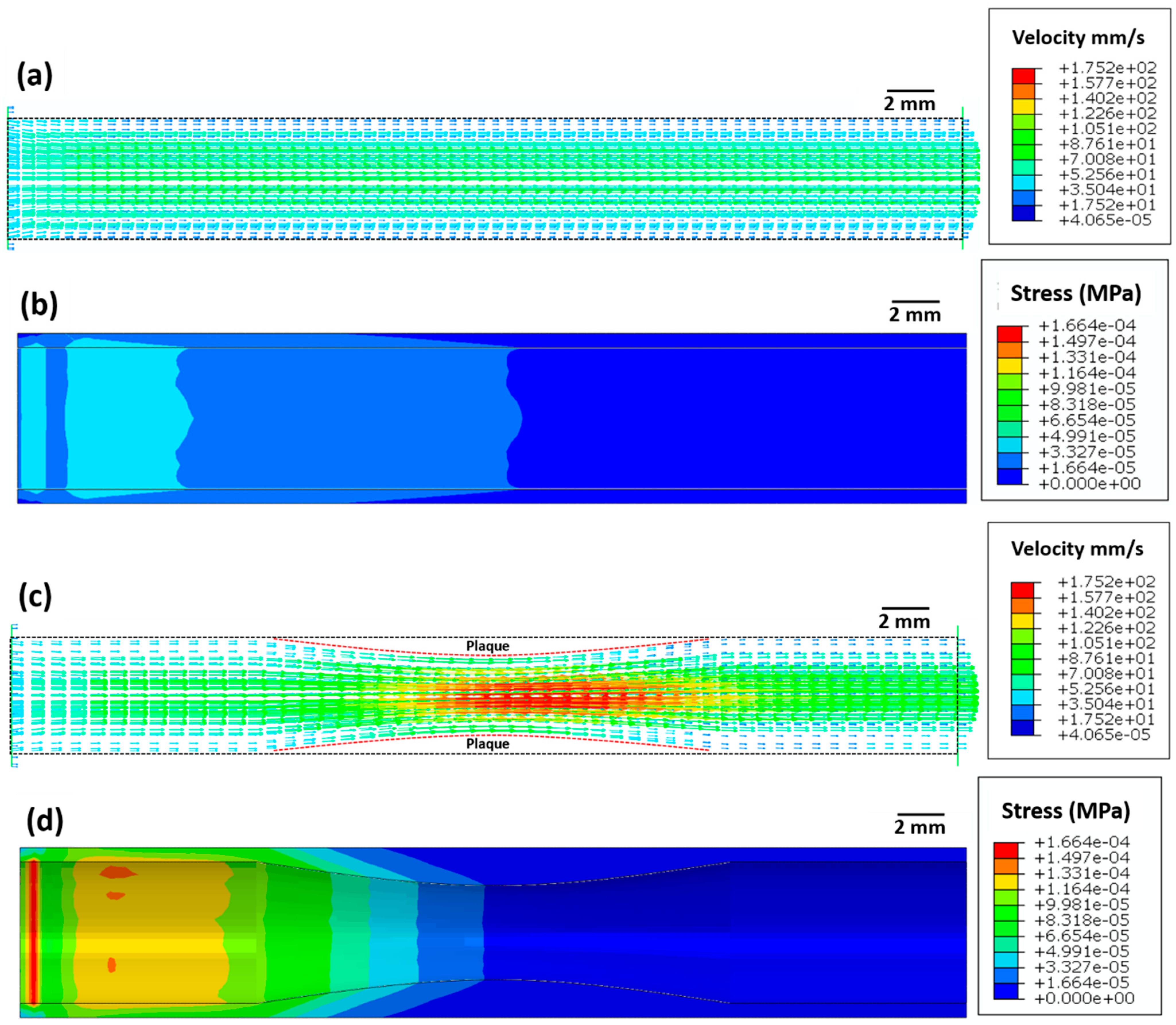
Figure 3 depicts the blood velocity contour profile for the artery without atherosclerosis (Figure 3a) and with atherosclerosis (Figure 3c). For the artery without atherosclerosis, the blood velocity at the centre of the artery is slightly higher (≈70 mm/s) compared to the inlet velocity (50 mm/s) (Figure 3a). However, a significantly higher blood velocity (≈170 mm/s) is observed in the artery near the plaque region due to a decrease in the cross-sectional area (Figure 3c). Applying Bernoulli’s theorem qualitatively, an increase in blood velocity leads to a decrease in blood pressure and, thus, to a further decrease in the cross-sectional area. This strongly justifies the overall need for stent deployment in the artery.
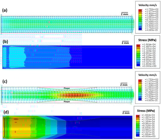
Figure 3.
Images showing (a,c) the blood flow velocity (mm/s) and (b,d) Von Mises stress (MPa) distribution in the artery (a,b) without atherosclerosis and (c,d) with atherosclerosis.
The maximum elastic stress on the arterial wall without atherosclerosis is very low (≈1.6 × 10⁻⁵ MPa, Figure 3b). However, the maximum elastic stress (≈1.6 × 10⁻⁴ MPa) on the arterial wall with atherosclerosis is ten times higher compared to that on the arterial wall without atherosclerosis. This increase in arterial wall stress likely leads to higher blood pressure, which in turn can increase the risk of myocardial infarction.
4.2. Stent Deployment System Simulation
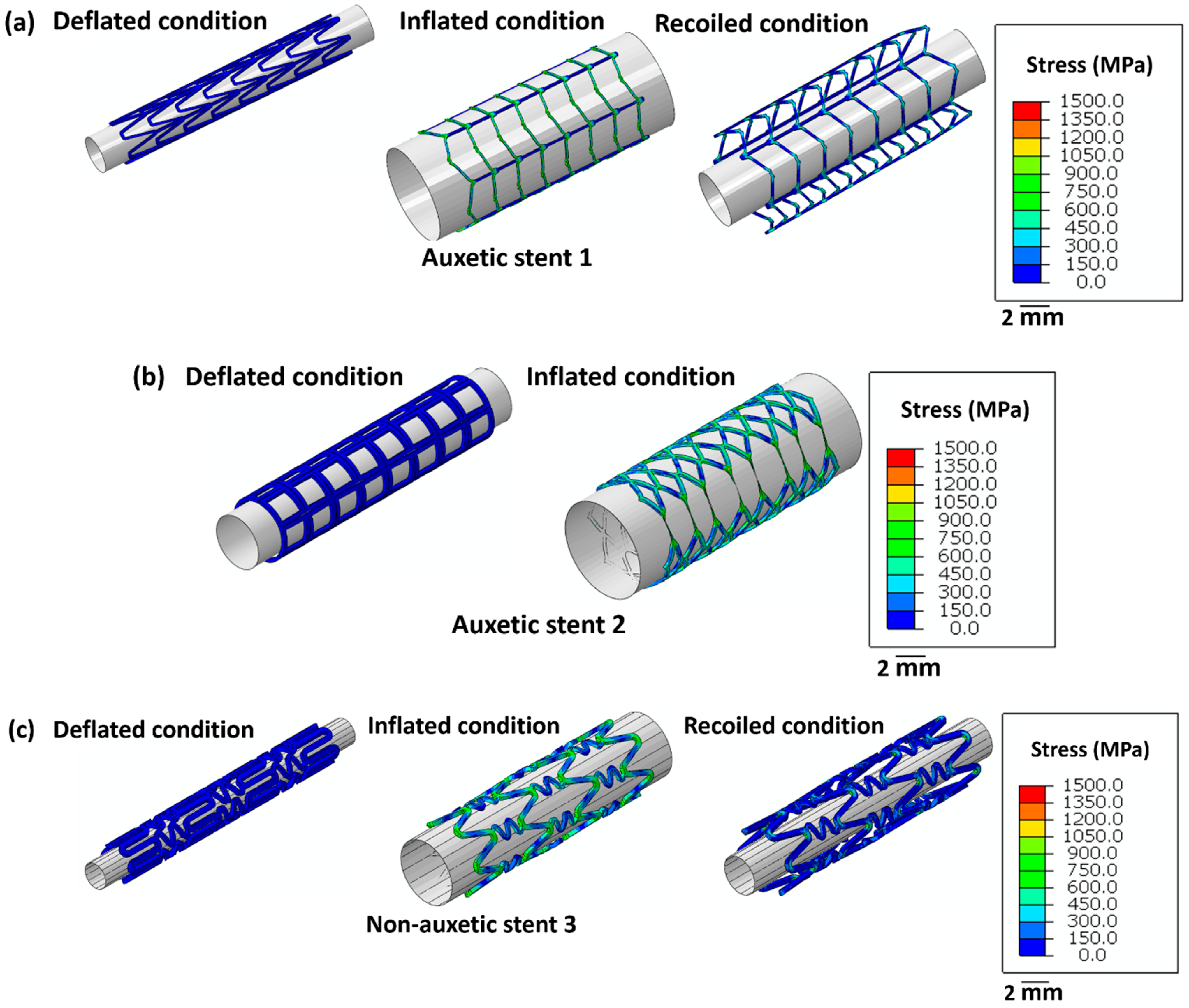
Figure 4 highlights the stress distribution in the stents for deflated, inflated, and recoiled conditions. Stent 1 and stent 3 reveal successful unrestricted deployment. However, stent 2 shows excessive thinning of the struts during inflation, indicating structural failure during balloon expansion. Stent 1 exhibits lower radial recoil than stent 3.
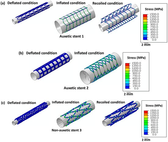
Figure 4.
Images of the unrestricted stent deployment model showing the Von Mises stress (MPa) distribution within (a) stent 1, (b) stent 2, and (c) stent 3. Stents 1 and stent 3 are in deflated, inflated, and recoiled conditions. Due to strut failure, stent 2 is presented only in a deflated condition and inflated condition. The CAD designs of the auxetic and non-auxetic stent are from literature [14,16,21,22,50]. The expansion and contraction behaviour of the stents are studied by FEM analysis.
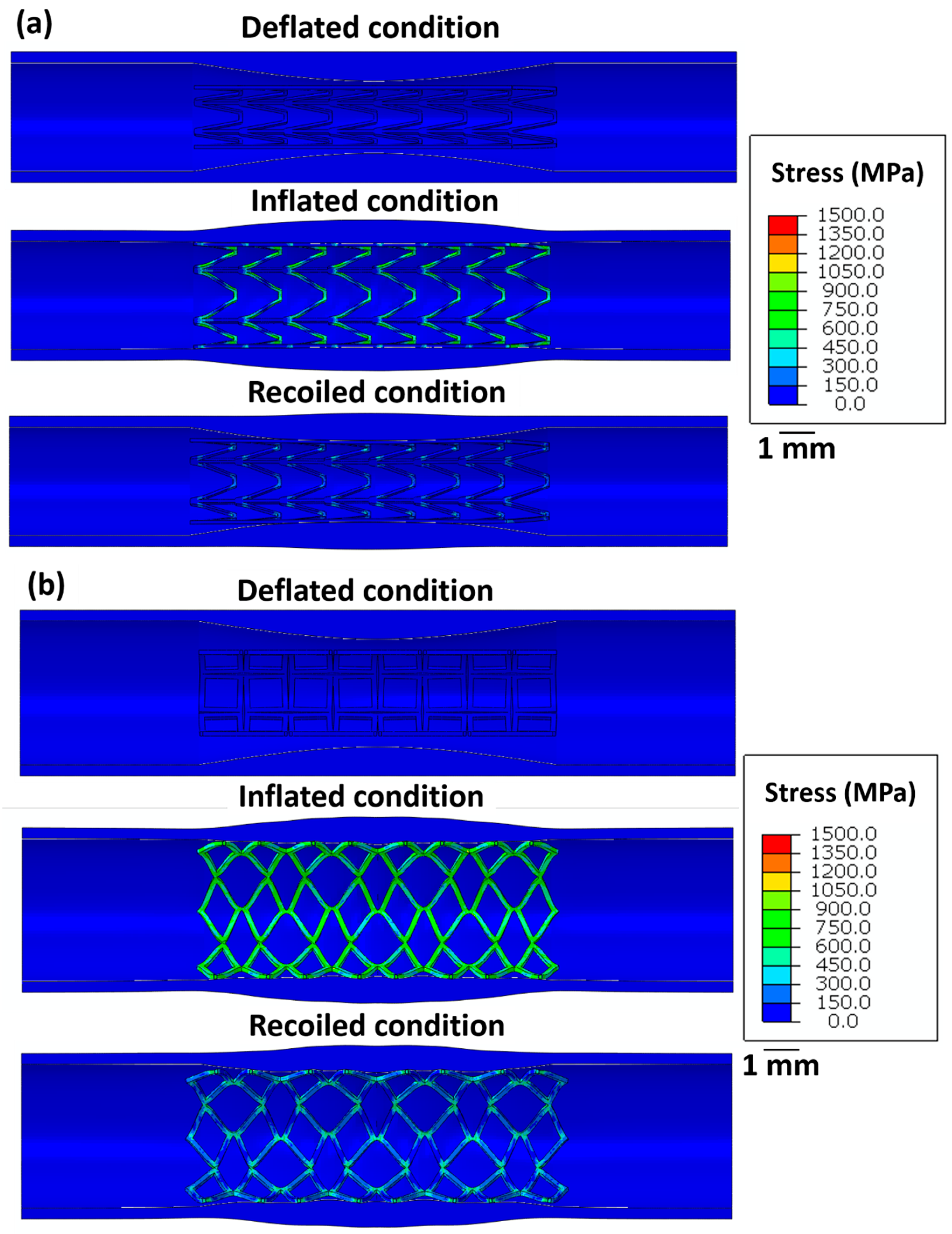
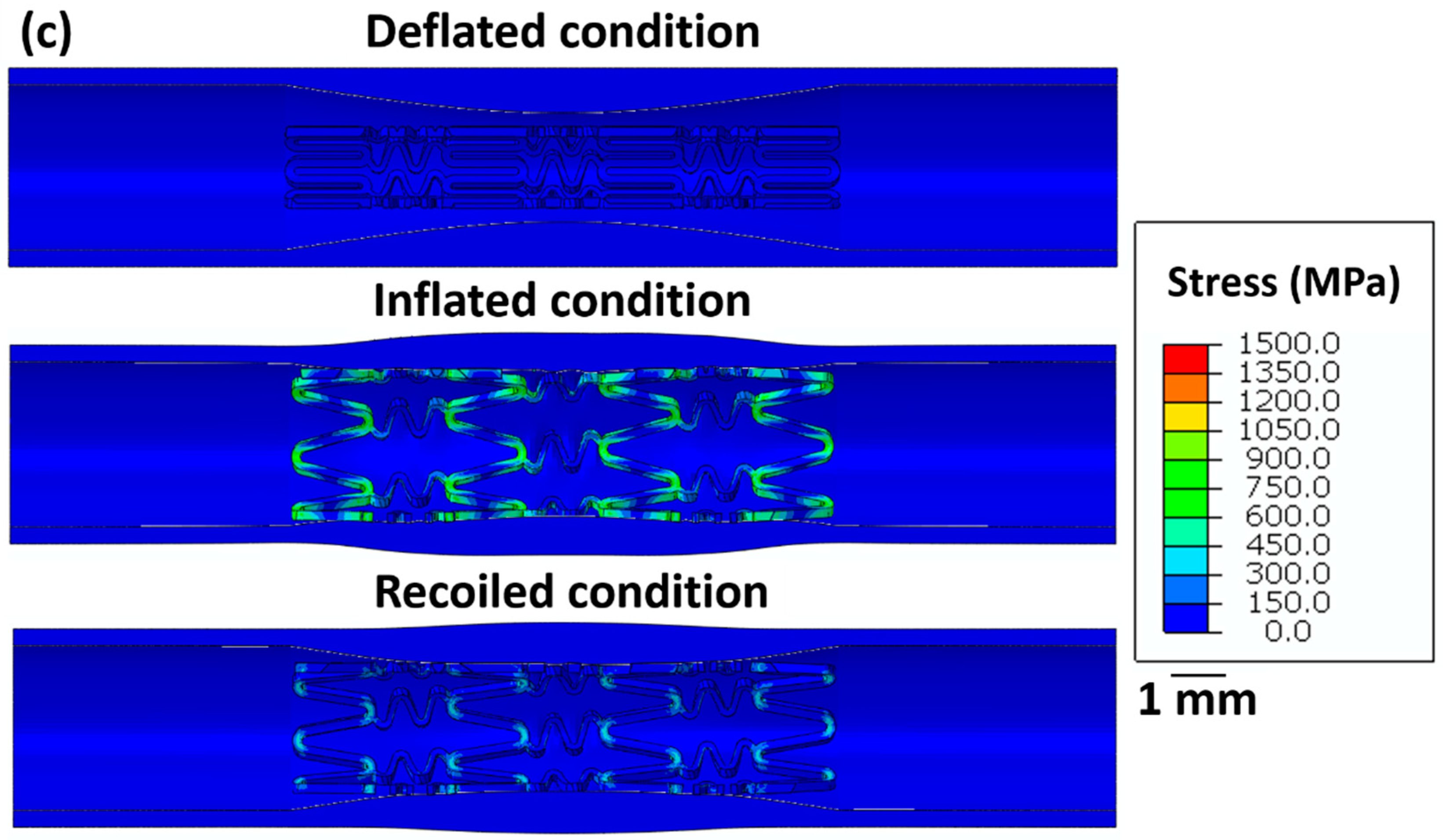
Figure 5 summarises the stress distribution in all stents for the deflated, inflated, and recoiled states of the restricted stent deployment system. Successful deployment of all stent designs is observed here. In the inflated state, stress concentrations are noticed at the strut corners of stent 1. Due to the hyper-elasticity of the arterial layers and contraction of the balloon, recoil in stent 1 is observed. However, the arterial diameter at its minimum point increased by 13% in the recoiled state compared to the deflated. Compared with the unrestricted stent deployment, the restricted stent deployment of stent 2 shows no strut failure or structural instability. In the inflated state, the stress remains distributed within the stent and no stress concentration is observed. The deployment of stent 2 results in a 19% increase in the arterial diameter at its minimal point. For stent 3, stress concentration is noticed in struts in the inflated condition but is severely reduced in the recoiled conditions. In the recoiled state, only a 10% increase in the artery diameter at the minimum point is observed.
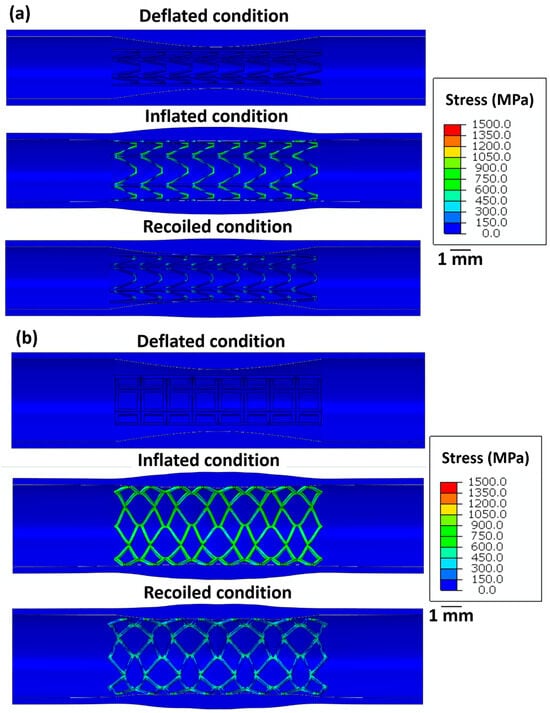
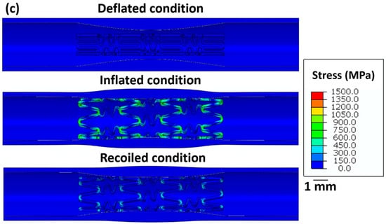
Figure 5.
Longitudinal cross-sectional images of the restricted stent deployment model showing the Von Mises stress (MPa) distribution within (a) stent 1, (b) stent 2, and (c) stent 3 for the deflated, inflated, and recoiled conditions. The CAD designs of the auxetic and non-auxetic stent are from literature [14,16,21,22,50]. The expansion and contraction behaviour of the stents are studied by FEM analysis.
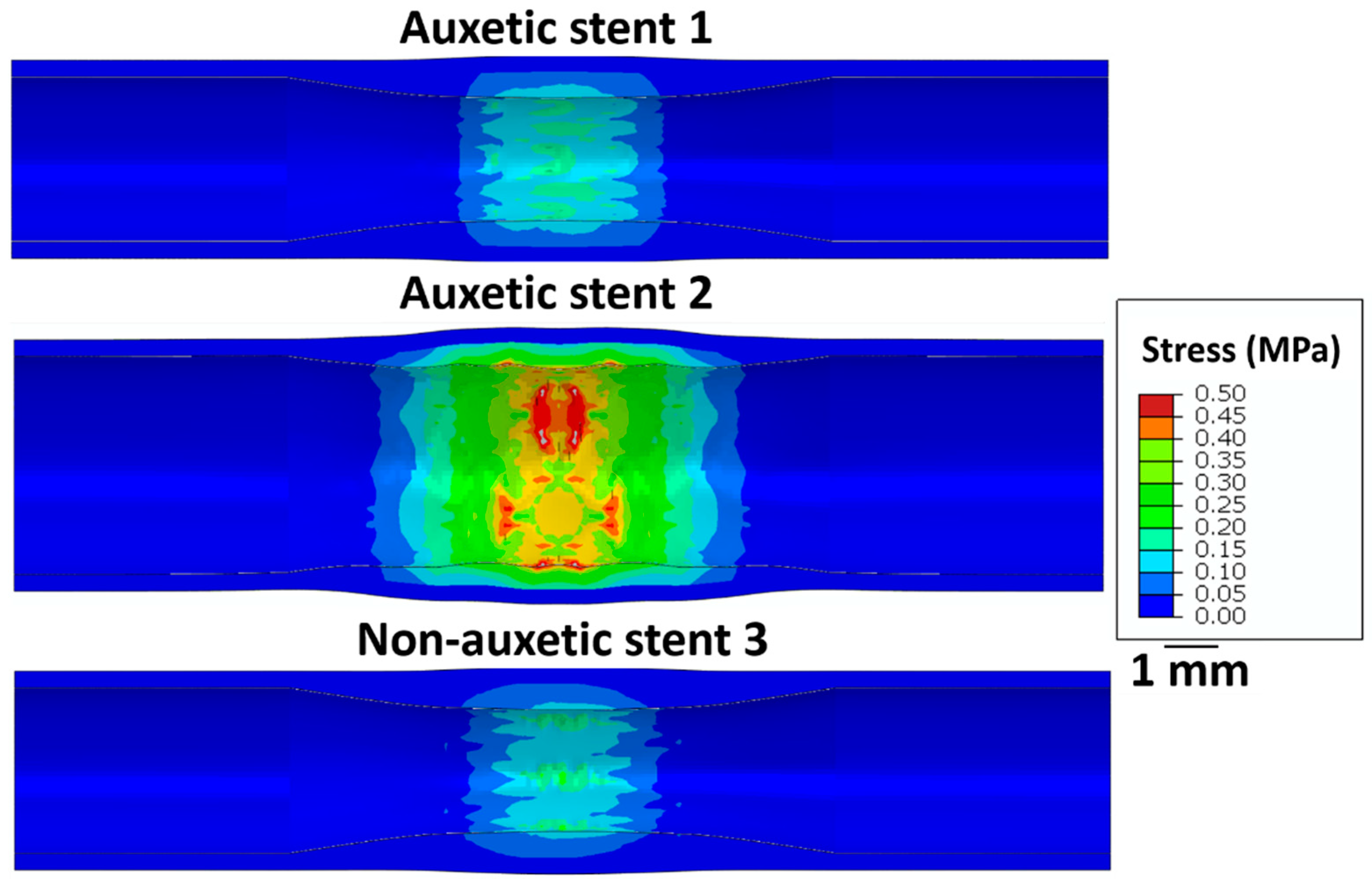
Figure 6 shows the stress on the intima layer of the artery after the stent deployment. Stent 2 exhibits the highest stress (≈0.5 MPa) on the arterial wall leading to possible perforations after deployment. Stent 1 and stent 3 exhibit relatively lower stress (0.2 MPa) on the arterial layer. Therefore, the restricted deployment of stent 1 and stent 3 is safe compared to stent 2.

Figure 6.
Longitudinal cross-sectional images of the restricted stent deployment model showing the Von Mises stress (MPa) distribution on the intima layer of an artery for stent 1, stent 2, and stent 3 for the recoiled conditions. The CAD designs of the auxetic and non-auxetic stent are from literature [14,16,21,22,50].
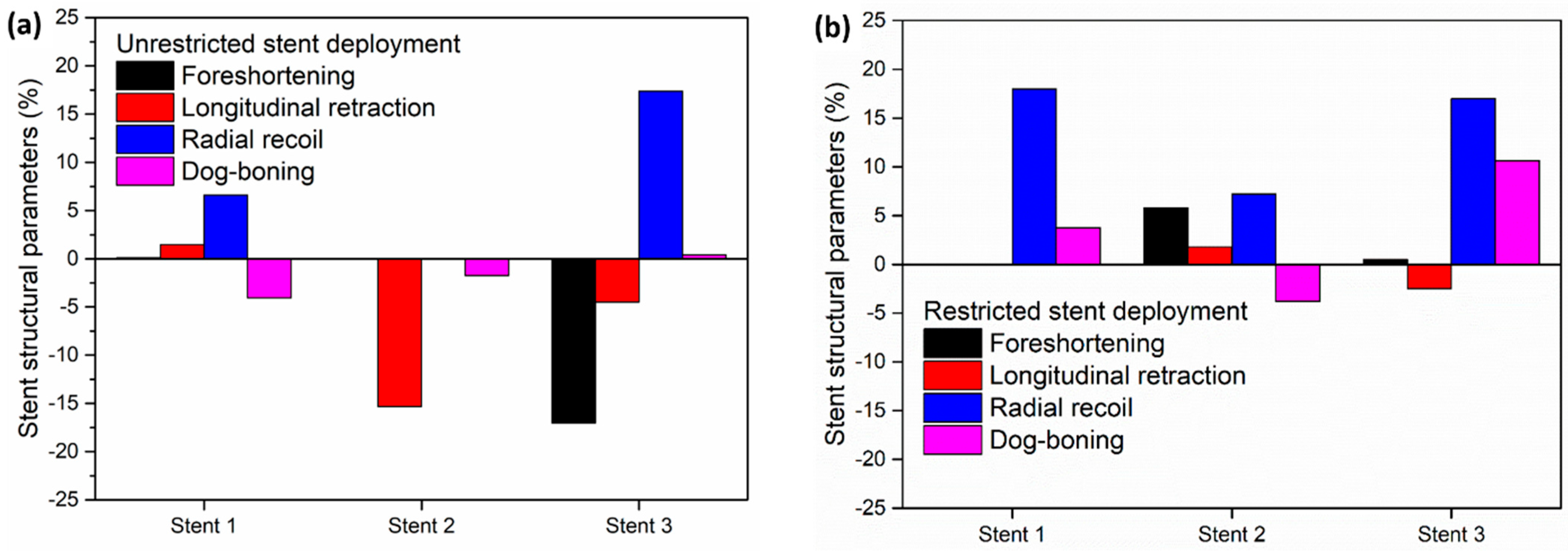
To compare the performance of different stent designs, Figure 7 depicts the output structural parameters of the stents in the unrestricted deployment (Figure 7a) and restricted deployment (Figure 7b) models.

Figure 7.
Stent structural parameters for (a) unrestricted stent deployment and (b) restricted stent deployment.
In the unrestricted stent deployment model, due to the failure of the struts in stent 2, foreshortening, radial recoil, and dog-boning are not calculated (Figure 7a). In the unrestricted stent deployment model, the foreshortening magnitude is significantly less for stent 1 (<1%) than for stent 3 (>15%). Similarly, the longitudinal retraction magnitude of stent 1 is very small compared to that of stent 3. Less foreshortening and less longitudinal retraction of stent 1 reduce the risk of damage to the arterial wall during deployment. In addition, the radial recoil of stent 3 (>15%) is higher compared to that of stent 1 (≈6%) during unrestricted deployment. This should lead to a higher increase in arterial blood flow volume after deployment of stent 1 compared to stent 3.
In Figure 7b, for the restricted stent deployment model, stent 1 shows very low foreshortening (0.02%) and very low longitudinal retraction (0.02%) compared to stent 2 and stent 3. The dog-boning of stent 1 is 3.7%, which is lower than that for stent 3 (10.6%). However, the radial recoil values of stent 1 and stent 3 are nearly the same (≈18%). Stent 2 shows lower foreshortening and lower longitudinal retraction compared to stent 1 and stent 3. Stent 2 presents a negative dog-boning compared to stent 1 and stent 3, which indicates that the stent diameter at the ends is lower than the stent diameter at the centre. Although the structural performance of stent 2 is superior to stent 1 and stent 3, it cannot be recommended due to the higher stress on the artery wall during deployment.
4.3. Powder Characterisation
In Figure 8, SEM images of the powder particles for the Ti2448 alloy are depicted. The particles are spherical in size with a varying size distribution. The size of the powder particles varies between 10 µm and 120 μm. The red curve in Figure 8b represents the log-normal curve fitting with an average particle size of 50 μm.
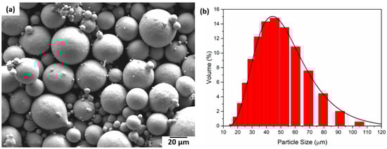
Figure 8.
(a) SEM micrograph of the Ti2448 powder particles and (b) Ti2448 particle size distribution.
4.4. Processing of Samples
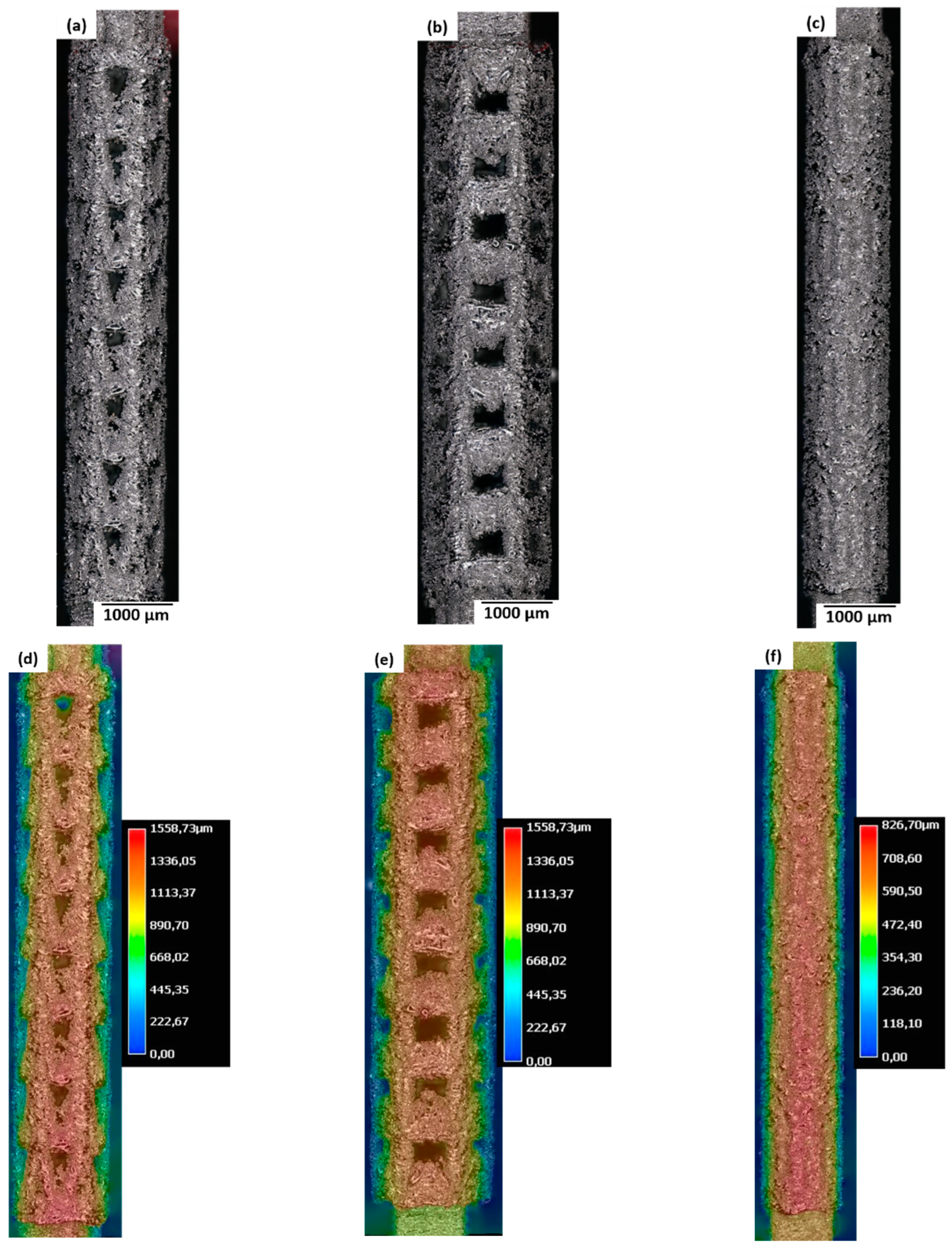
Figure 9a–c give an overview of stent 1, stent 2, and stent 3 via optical micrographs and the local topography (Figure 9d–f). The as-built samples show massive thickening of the struts leading to inaccurate dimensions and loss of fine-scale design details of stents after LPBF. All stents present a loss of design features, but stent 3 shows an extreme amount of loss of design resolution. This phenomenon can be attributed to two reasons: the size of the melt pool being higher than the laser beam diameter, and the sticking of the unmolten powder particles (surrounding the melt pool) during the cooling of the melted region. In this regard, the size of the strut in the stent design is 0.05 mm, which is comparable to the laser spot size (0.045 mm). Thus, coarsening of the struts is expected due to melt pool size expansion. Hence, another possibility is to use a smaller laser spot size; however, the laser spot size is limited by the LPBF machine. In the current investigation, a 0.045 mm laser spot size is the smallest spot size specified by the LPBF machine manufacturer.

Figure 9.
(a–c) Optical micrographs and (d–f) local surface height of the as-built samples for (a,d) stent 1, (b,e) stent 2, and (c,f) stent 3. The CAD designs of the auxetic and non-auxetic stent are from literature [14,16,21,22,50].
Considering the dimensional inaccuracies in the as-built stent samples compared to the CAD model, a major revision of the processing parameters is needed. The processing parameters can be optimised by trying to make samples with overhangs with 40°, 50°, and 60° angles at different parameters. Similar parameter optimisation is reported in previous literature [59,60,61,62,63]. The scanning strategies and process parameters play an important role in the manufacturing quality of the overhangs. The surface roughness of the overhangs was decreased due to the optimisation of the scanning strategies and the processing parameters [61]. Another study on the processing of overhanging structures using 316 L steel revealed that when the layer thickness is comparable to the particle diameter, the gaps between the layers could be filled by the particles, leading to lower surface roughness [63].
Post-processing of the stent is needed to improve the surface finish of the stent. The surface finish can be improved by Al2O3 bead blasting. Al2O3 bead blasting leads to an increase in surface roughness leading to an increase in surface area which leads to better osseointegration [64]. As the microstructure of the stent samples contains a major fraction of the metastable β phase, no heat treatment is needed. However, stress relief annealing is needed to remove the residual stress generated during LPBF processing.
4.5. Tensile Test
Figure 10a–c summarise the DIC images (presenting strain before fracture) and the optical micrographs recorded after the fracture. Following the DIC images, stent 1 shows strain concentration near the lower and upper clamping sections, indicating an equal probability of fracture in the two regions. Failure of the samples occurs at the lower clamping section as reinforced by the optical micrograph image (Figure 10a). Figure 10b (DIC image) presents a high-strain region highlighted by a black arrow near the middle section of stent 2, which in turn matches the fracture region of stent 2. Stent 3 manifests a high-strain region (shown by a yellow arrow) close to the upper clamping section. Figure 10d shows the stress–strain curves of the stents. The tensile properties calculated from the stress–strain curve are presented in Table 7.
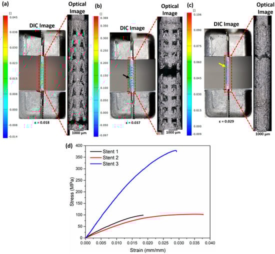
Figure 10.
DIC and optical micrographs after fracture of (a) stent 1, (b) stent 2, and (c) stent 3 and (d) stress–strain curves of the as-built stents. The DIC images represent the surface directly before fracture. The black arrow in (b) and the yellow arrow in (c) highlight the region with the highest strain. The CAD designs of the auxetic and non-auxetic stent are from literature [14,16,21,22,50].
4.6. Tensile Test Simulations
The Von Mises stress distribution obtained from the FEM simulations after tensile testing is presented in Figure 11. The vertical struts in stent 1 carry most of the load and undergo necking (highlighted by red arrows, Figure 11a). For stent 2, the opening of the cells is observed upon tensile testing. Most of the load is concentrated at the nodes (meeting point of struts, Figure 11b) of the cells. Stent 3 shows the elongation of the middle connecting struts (Figure 11c). Tensile stress–strain curves obtained from the tensile tests of the three stents are shown in Figure 11d. Stent 1 exhibits the lowest strain (<0.05) due to strut failure; however, stent 2 and stent 3 show no failure after 0.5 (mm/mm) strain. The slope of the stress–strain curve shows two distinct slopes for stent 3. The lower slope in the initial part of the stress–strain curve is due to the reorientation of the struts in the middle part of stent 2, while the higher slope in the later part of the stress–strain curve is due to the stretching of the struts in the middle part of stent 2 (highlighted in blue curve Figure 11d).
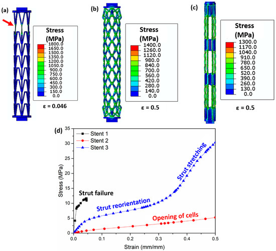
Figure 11.
Images obtained after FEM simulations showing the Von Mises stress (MPa) distribution during tensile testing in (a) stent 1, (b) stent 2, and (c) stent 3 and (d) stress–strain curve of all stents. The red arrow in (a) highlights the struts’ failure. Figure 11a is the stress distribution at a strain of 0.046 (mm/mm), (b) shows the stress distribution at a strain of 0.5 (mm/mm), and (c) presents the stress distribution at a strain of 0.5 (mm/mm). The CAD designs of the auxetic and non-auxetic stent are from literature [14,16,21,22,50].
Both the experimental stress–strain curve and the simulated stress–strain curve confirm short elongations for stent 1. In contrast, the experimental stress–strain curves of stent 2 and stent 3 reveal short elongations (<0.04 mm/mm strain), while the simulation results show no structural failure until 0.5 (mm/mm) strain. This is attributed to the massive thickening of the struts leading to dimensional inaccuracies during LPBF.
Table 7 compares the experimentally observed and the simulated tensile properties. The effective elastic modulus and fracture stress of the as-built stent 1, stent 2, and stent 3 samples are higher than those obtained from simulations. This is due to the difference in the dimensions between the as-built sample and the simulations. Also, the fracture stress of the as-built stent 1 sample is higher than the simulated values. The fracture stress and the fracture strain of stent 2 and stent 3 are not reported as no fracture is observed for these stent designs during simulations.
5. Conclusions
The additively manufactured stents have poor dimensional tolerance as compared to the CAD model. So, appropriate parameter optimisation during LPBF processing needs to be undertaken. This is a possible future work. Another possible future work is the design and fabrication of new auxetic stent types. Based on the experimental and computational modelling investigations on the stents, the following conclusions can be drawn:
- CFD simulations of the blood flow predict a twenty-fold increase in blood velocity near the plaque region of a stenosed artery compared to a non-stenosed artery. A ten-fold increase in the stress on the arterial wall due to blood flow is noticed due to atherosclerosis. This could lead to the tearing of the arterial wall near the plaque region.
- Unrestricted stent deployment results in structural instability (strut failure) for auxetic stent 2. Auxetic stent 1 presents very low foreshortening, longitudinal retraction, and radial recoil compared to the non-auxetic stent 3.
- Under restricted deployment of the stent, the performance of auxetic stent 1 is better than that of auxetic stent 2 and non-auxetic stent 3. Stent 1 shows no foreshortening and longitudinal retraction compared with stent 2 and stent 3. However, the radial recoil is higher in stent 1 than in stent 3. No structural instability is observed in stent 2 under restricted deployment.
- The as-built stent samples show strut coarsening and a loss of fine-scale details after LPBF processing compared to the design. Stent 3 presents an extreme loss of resolution after LPBF compared to stent 1 and stent 2. The simulated tensile tests of the stents show strut failure for stent 1, resulting in a short elongation to failure, whereas stent 2 and stent 3 show no structural failure until 0.5 (mm/mm) strain.
Author Contributions
Conceptualization, S.P.; methodology, S.P. and D.M.; software, S.P.; validation, S.P. and D.M.; formal analysis, S.P. and D.M.; investigation, S.P. and D.M.; resources, M.H., K.-P.H. and M.S.; data curation, S.P.; writing—original draft preparation, S.P.; writing—review and editing, D.M., M.H., K.-P.H. and M.S.; visualization, S.P.; supervision, K.-P.H. and M.S.; project administration, K.-P.H. and M.S.; funding acquisition, M.S. All authors have read and agreed to the published version of the manuscript.
Funding
This research received no external funding.
Data Availability Statement
The raw and processed data associated with the findings cannot be shared. It forms part of an ongoing study.
Acknowledgments
Fabian Lienen is acknowledged for optical microscopy imaging and performing the tensile test of the stents.
Conflicts of Interest
The authors declare no conflict of interest.
References
- Mancini, D.; Colombo, P.C. Left Ventricular Assist Devices: A Rapidly Evolving Alternative to Transplant. J. Am. Coll. Cardiol. 2015, 65, 2542–2555. [Google Scholar] [CrossRef] [PubMed]
- Friede, A.; O’Carroll, P.W.; Thralls, R.B.; Reid, J.A. CDC WONDER on the Web. Proc. AMIA Annu. Fall Symp. 1996, 408–412. Available online: https://pubmed.ncbi.nlm.nih.gov/8947698/ (accessed on 21 December 2022).
- Nichols, M.; Townsend, N.; Scarborough, P.; Rayner, M. Cardiovascular disease in Europe 2014: Epidemiological update. Eur. Heart J. 2014, 35, 2929. [Google Scholar] [CrossRef] [PubMed]
- Roth, G.A.; Al, E. Global, regional, and national age-sex-specific mortality for 282 causes of death in 195 countries and territories, 1980–2017: A systematic analysis for the Global Burden of Disease Study 2017. Lancet 2018, 392, 1736–1788. [Google Scholar] [CrossRef] [PubMed]
- Lloyd-Jones, D.; Adams, R.J.; Brown, T.M.; Carnethon, M.; Dai, S.; De Simone, G.; Ferguson, T.B.; Ford, E.; Furie, K.; Gillespie, C.; et al. Wylie-Rosett, Executive summary: Heart disease and stroke statistics—2010 update: A report from the american heart association. Circulation 2010, 121, 948–954. [Google Scholar] [CrossRef]
- Rosamond, W.; Flegal, K.; Furie, K.; Go, A.; Greenlund, K.; Haase, N.; Hailpern, S.M.; Ho, M.; Howard, V.; Kissela, B.; et al. Heart disease and stroke statistics—2008 update: A report from the American Heart Association Statistics Committee and Stroke Statistics Subcommittee. Circulation 2008, 117, e25–e146. [Google Scholar] [CrossRef]
- World Health Statistics. 2012. Available online: https://www.who.int/docs/default-source/gho-documents/world-health-statistic-reports/world-health-statistics-2012.pdf (accessed on 7 September 2023).
- OPTN: Organ Procurement and Transplantation Network—OPTN, (n.d.). Available online: https://optn.transplant.hrsa.gov/ (accessed on 14 August 2022).
- Wang, T.; Butany, J. Pathogenesis of atherosclerosis. Diagn. Histopathol. 2017, 23, 473–478. [Google Scholar] [CrossRef]
- Douglas, G.; Channon, K.M. The pathogenesis of atherosclerosis. Medicine 2014, 42, 480–484. [Google Scholar] [CrossRef]
- Hu, T.; Yang, J.; Cui, K.; Rao, Q.; Yin, T.; Tan, L.; Zhang, Y.; Li, Z.; Wang, G. Controlled Slow-Release Drug-Eluting Stents for the Prevention of Coronary Restenosis: Recent Progress and Future Prospects. ACS Appl. Mater. Interfaces 2015, 7, 11695–11712. [Google Scholar] [CrossRef]
- Yang, C.S.; Wu, H.C.; Sun, J.S.; Hsiao, H.M.; Wang, T.W. Thermo-induced shape-memory PEG-PCL copolymer as a dual-drug-eluting biodegradable stent. ACS Appl. Mater. Interfaces 2013, 5, 10985–10994. [Google Scholar] [CrossRef]
- Brie, D.; Penson, P.; Serban, M.-C.; Toth, P.P.; Simonton, C.; Serruys, P.W.; Banach, M. Bioresorbable scaffold—A magic bullet for the treatment of coronary artery disease? Int. J. Cardiol. 2016, 215, 47–59. [Google Scholar] [CrossRef]
- De Beule, M.; Mortier, P.; Carlier, S.G.; Verhegghe, B.; Van Impe, R.; Verdonck, P. Realistic finite element-based stent design: The impact of balloon folding. J. Biomech. 2008, 41, 383–389. [Google Scholar] [CrossRef] [PubMed]
- Lally, C.; Dolan, F.; Prendergast, P.J. Cardiovascular stent design and vessel stresses: A finite element analysis. J. Biomech. 2005, 38, 1574–1581. [Google Scholar] [CrossRef]
- Martin, D.; Boyle, F. Finite element analysis of balloon-expandable coronary stent deployment: Influence of angioplasty balloon configuration. Int. J. Numer. Methods Biomed. Eng. 2013, 29, 1161–1175. [Google Scholar] [CrossRef] [PubMed]
- Ragkousis, G.E.; Curzen, N.; Bressloff, N.W. Computational Modelling of Multi-folded Balloon Delivery Systems for Coronary Artery Stenting: Insights into Patient-Specific Stent Malapposition. Ann. Biomed. Eng. 2015, 43, 1786–1802. [Google Scholar] [CrossRef] [PubMed]
- Rahinj, G.B.; Chauhan, H.S.; Sirivella, M.L.; Satyanarayana, M.V.; Ramanan, L. Numerical Analysis for Non-Uniformity of Balloon-Expandable Stent Deployment Driven by Dogboning and Foreshortening. Cardiovasc. Eng. Technol. 2021, 13, 247–264. [Google Scholar] [CrossRef] [PubMed]
- Azaouzi, M.; Makradi, A.; Belouettar, S. Numerical investigations of the structural behavior of a balloon expandable stent design using finite element method. Comput. Mater. Sci. 2013, 72, 54–61. [Google Scholar] [CrossRef]
- Okereke, M.I.; Khalaj, R.; Tabriz, A.G.; Douroumis, D. Development of 3D printable bioresorbable coronary artery stents: A virtual testing approach. Mech. Mater. 2021, 163, 104092. [Google Scholar] [CrossRef]
- Umer, M.; Ali, M.N.; Mubashar, A.; Mir, M. Computational modeling of balloon-expandable stent deployment in coronary artery using the finite element method. Res. Rep. Clin. Cardiol. 2019, 10, 43–56. [Google Scholar] [CrossRef]
- Bukhari, F.; Ansari, U.; Ali, M.N.; Akhtar, H.; Asif, S.; Mohammad, U.; Mir, M. A Biaxial Strain–Based Expansion Mechanism for Auxetic Stent Deployment. J. Appl. Biomater. Funct. Mater. 2017, 15, 196–205. [Google Scholar] [CrossRef]
- Ang, H.Y.; Toong, D.; Chow, W.S.; Seisilya, W.; Wu, W.; Wong, P.; Venkatraman, S.S.; Foin, N.; Huang, Y. Radiopaque Fully Degradable Nanocomposites for Coronary Stents. Sci. Rep. 2018, 8, 17409. [Google Scholar] [CrossRef] [PubMed]
- Khalaj, R.; Tabriz, A.G.; Okereke, M.I.; Douroumis, D. 3D printing advances in the development of stents. Int. J. Pharm. 2021, 609, 121153. [Google Scholar] [CrossRef] [PubMed]
- Wu, Z.; Zhao, J.; Wu, W.; Wang, P.; Wang, B.; Li, G.; Zhang, S. Radial Compressive Property and the Proof-of-Concept Study for Realizing Self-expansion of 3D Printing Polylactic Acid Vascular Stents with Negative Poisson’s Ratio Structure. Materials 2018, 11, 1357. [Google Scholar] [CrossRef] [PubMed]
- Chen, C.; Tan, J.; Wu, W.; Petrini, L.; Zhang, L.; Shi, Y.; Cattarinuzzi, E.; Pei, J.; Huang, H.; Ding, W.; et al. Modeling and Experimental Studies of Coating Delamination of Biodegradable Magnesium Alloy Cardiovascular Stents. ACS Biomater. Sci. Eng. 2018, 4, 3864–3873. [Google Scholar] [CrossRef]
- Walker, J.; Andani, M.T.; Haberland, C.; Elahinia, M. Additive Manufacturing of Nitinol Shape Memory Alloys to Overcome Challenges in Conventional Nitinol Fabrication. In Proceedings of the ASME International Mechanical Engineering Congress and Exposition, Montreal, QC, Canada, 14–20 November 2014. [Google Scholar] [CrossRef]
- Demir, A.G.; Previtali, B. Additive manufacturing of cardiovascular CoCr stents by selective laser melting. Mater. Des. 2017, 119, 338–350. [Google Scholar] [CrossRef]
- Safdel, A.; Elbestawi, M.A. Distortion and printability of stent structures in laser powder bed fusion processing of NiTi alloys. Mater. Lett. 2021, 300, 130163. [Google Scholar] [CrossRef]
- Lesyk, D.; Lymar, O.; Dzhemelinkyi, V. Surface Characterization of the Cobalt-Based Alloy Stents Fabricated by 3D Laser Metal Fusion Technology. Lect. Notes Networks Syst. 2021, 233, 357–364. [Google Scholar] [CrossRef]
- Finazzi, V.; Berti, F.; Guillory, R.J., II; Petrini, L.; Previtali, B.; Demir, A.G. Patient-specific cardiovascular superelastic NiTi stents produced by laser powder bed fusion. Procedia CIRP 2022, 110, 242–246. [Google Scholar] [CrossRef]
- Xiong, Z.; Li, H.; Yang, H.; Yang, Y.; Liu, Y.; Cui, L.; Li, X.; Masseling, L.; Shen, L.; Hao, S. Micro laser powder bed fusion of NiTi alloys with superior mechanical property and shape recovery function. Addit. Manuf. 2022, 57, 102960. [Google Scholar] [CrossRef]
- Jamshidi, P.; Panwisawas, C.; Langi, E.; Cox, S.C.; Feng, J.; Zhao, L.; Attallah, M.M. Development, characterisation, and modelling of processability of nitinol stents using laser powder bed fusion. J. Alloys Compd. 2022, 909, 164681. [Google Scholar] [CrossRef]
- Abdelaal, O.; Hengsbach, F.; Schaper, M.; Hoyer, K.P. LPBF Manufactured Functionally Graded Lattice Structures Obtained by Graded Density and Hybrid Poisson’s Ratio. Materials 2022, 15, 4072. [Google Scholar] [CrossRef] [PubMed]
- Zhang, K.; Liu, T.; Li, J.; Chen, J.; Wang, J.; Huang, N. Surface modification of implanted cardiovascular metal stents: From antithrombosis and antirestenosis to endothelialization. J. Biomed. Mater. Res. Part A 2013, 102, 588–609. [Google Scholar] [CrossRef] [PubMed]
- Mani, G.; Feldman, M.D.; Patel, D.; Agrawal, C.M. Coronary stents: A materials perspective. Biomaterials 2007, 28, 1689–1710. [Google Scholar] [CrossRef] [PubMed]
- Park, J.B.; Kim, Y.K. Metallic Biomaterials. Biomed. Eng. Fundam. 2014. [Google Scholar] [CrossRef]
- Köster, R.; Vieluf, D.; Kiehn, M.; Sommerauer, M.; Kähler, J.; Baldus, S.; Meinertz, T.; Hamm, C.W. Nickel and molybdenum contact allergies in patients with coronary in-stent restenosis. Lancet 2000, 356, 1895–1897. [Google Scholar] [CrossRef]
- Bartusek, K.; Dokoupil, Z.; Gescheidtova, E. Magnetic field mapping around metal implants using an asymmetric spin-echo MRI sequence. Meas. Sci. Technol. 2006, 17, 3293–3300. [Google Scholar] [CrossRef]
- Wang, L.; Dou, Q.; Fletcher, P.T.; Speidel, S.; Li, S. Medical Image Computing and Computer Assisted Intervention—MICCAI 2022. In Proceedings of the 25th International Conference, Singapore, 18–22 September 2022; Volume 13436. [Google Scholar] [CrossRef]
- Cho, K.; Niinomi, M.; Nakai, M.; Hieda, J. Development of High Modulus Ti–Fe–Cu Alloys for Biomedical Applications. Mater. Trans. 2013, 54, 574–581. [Google Scholar] [CrossRef]
- Zafar, H.; Sharif, F.; Leahy, M.J. Measurement of the blood flow rate and velocity in coronary artery stenosis using intracoronary frequency domain optical coherence tomography: Validation against fractional flow reserve. IJC Hear. Vasc. 2014, 5, 68–71. [Google Scholar] [CrossRef]
- Sharif, D.; Sharif-Rasslan, A.; Shahla, C.; Khalil, A.; Rosenschein, U. Differences in coronary artery blood velocities in the setting of normal coronary angiography and normal stress echocardiography. Hear. Int. 2015, 10, e6–e11. [Google Scholar] [CrossRef]
- Heller, L.I.; Silver, K.H.; Villegas, B.J.; Balcom, S.J.; Weiner, B.H. Blood flow velocity in the right coronary artery: Assessment before and after angioplasty. J. Am. Coll. Cardiol. 1994, 24, 1012–1017. [Google Scholar] [CrossRef]
- Kern, M.J.; Tatineni, S.; Gudipati, C.; Aguirre, F.; Ring, M.E.; Serota, H.; Deligonul, U. Regional coronary blood flow velocity and vasodilator reserve in patients with angiographically normal coronary arteries. Coron. Artery Dis. 1990, 1, 579–590. Available online: https://journals.lww.com/coronary-artery/Fulltext/1990/09000/Regional_coronary_blood_flow_velocity_and.10.aspx (accessed on 7 September 2023). [CrossRef]
- Goddi, A.; Bortolotto, C.; Fiorina, I.; Raciti, M.V.; Fanizza, M.; Turpini, E.; Boffelli, G.; Calliada, F. High-frame rate vector flow imaging of the carotid bifurcation. Insights Imaging 2017, 8, 319–328. [Google Scholar] [CrossRef] [PubMed]
- Jahangiri, M.; Saghafian, M.; Sadeghi, M.R. Numerical study of turbulent pulsatile blood flow through stenosed artery using fluid-solid interaction. Comput. Math. Methods Med. 2015, 2015, 515613. [Google Scholar] [CrossRef] [PubMed]
- Torner, B.; Hallier, S.; Witte, M.; Wurm, F.H. Large-Eddy and Unsteady Reynolds-Averaged Navier-Stokes Simulations of an Axial Flow Pump for Cardiac Support. In Proceedings of the ASME Turbo Expo 2017: Turbomachinery Technical Conference and Exposition, Charlotte, NC, USA, 26–30 June 2017. [Google Scholar] [CrossRef]
- Mets, T. The entrepreneurial journey of a global start-up: The case of the open innovation platform GrabCAD. Int. J. Export. Mark. 2021, 4, 55. [Google Scholar] [CrossRef]
- Prodan, S. Stent|3D CAD Model Library|GrabCAD. 2017. Available online: https://grabcad.com/library/stent-9 (accessed on 20 August 2022).
- Bx_velocity Stent|3D CAD Model Library|GrabCAD. 2016. Available online: https://grabcad.com/library/bx_velocity-stent-1 (accessed on 20 August 2022).
- Hein, M.; Dias, N.F.L.; Pramanik, S.; Stangier, D.; Hoyer, K.P.; Tillmann, W.; Schaper, M. Heat Treatments of Metastable beta; Titanium Alloy Ti-24Nb-4Zr-8Sn Processed by Laser Powder Bed Fusion. Materials 2022, 15, 3774. [Google Scholar] [CrossRef] [PubMed]
- Lin, J.; Ozan, S.; Li, Y.; Ping, D.; Tong, X.; Li, G.; Wen, C. Novel Ti-Ta-Hf-Zr alloys with promising mechanical properties for prospective stent applications. Sci. Rep. 2016, 6, 37901. [Google Scholar] [CrossRef]
- Sidhu, S.S.; Singh, H.; Gepreel, M.A.H. A review on alloy design, biological response, and strengthening of β-titanium alloys as biomaterials. Mater. Sci. Eng. C 2020, 121, 111661. [Google Scholar] [CrossRef]
- Gervaso, F.; Capelli, C.; Petrini, L.; Lattanzio, S.; Di Virgilio, L.; Migliavacca, F. On the effects of different strategies in modelling balloon-expandable stenting by means of finite element method. J. Biomech. 2008, 41, 1206–1212. [Google Scholar] [CrossRef]
- Holzapfel, G.A.; Sommer, G.; Gasser, C.T.; Regitnig, P. Determination of layer-specific mechanical properties of human coronary arteries with nonatherosclerotic intimal thickening and related constitutive modeling. Am. J. Physiol. Circ. Physiol. 2005, 289, H2048–H2058. [Google Scholar] [CrossRef]
- Mortier, P.; Holzapfel, G.A.; De Beule, M.; Van Loo, D.; Taeymans, Y.; Segers, P.; Verdonck, P.; Verhegghe, B. A novel simulation strategy for stent insertion and deployment in curved coronary bifurcations: Comparison of three drug-eluting stents. Ann. Biomed. Eng. 2009, 38, 88–99. [Google Scholar] [CrossRef]
- Ju, F.; Xia, Z.; Sasaki, K. On the finite element modelling of balloon-expandable stents. J. Mech. Behav. Biomed. Mater. 2007, 1, 86–95. [Google Scholar] [CrossRef] [PubMed]
- Yang, T.; Liu, T.; Liao, W.; Wei, H.; Zhang, C.; Chen, X.; Zhang, K. Effect of processing parameters on overhanging surface roughness during laser powder bed fusion of AlSi10Mg. J. Manuf. Process. 2020, 61, 440–453. [Google Scholar] [CrossRef]
- Chen, Z.; Wu, X.; Tomus, D.; Davies, C.H.J. Surface roughness of Selective Laser Melted Ti-6Al-4V alloy components. Addit. Manuf. 2018, 21, 91–103. [Google Scholar] [CrossRef]
- Cloots, M.; Zumofen, L.; Spierings, A.B.; Kirchheim, A.; Wegener, K. Approaches to minimize overhang angles of SLM parts. Rapid Prototyp. J. 2017, 23, 362–369. [Google Scholar] [CrossRef]
- Fox, J.C.; Moylan, S.P.; Lane, B.M. Effect of Process Parameters on the Surface Roughness of Overhanging Structures in Laser Powder Bed Fusion Additive Manufacturing. Procedia Cirp 2016, 45, 131–134. [Google Scholar] [CrossRef]
- Strano, G.; Hao, L.; Everson, R.M.; Evans, K.E. Surface roughness analysis, modelling and prediction in selective laser melting. J. Am. Acad. Dermatol. 2013, 213, 589–597. [Google Scholar] [CrossRef]
- Hein, M.; Kokalj, D.; Dias, N.F.L.; Stangier, D.; Oltmanns, H.; Pramanik, S.; Kietzmann, M.; Hoyer, K.P.; Meißner, J.; Tillmann, W.; et al. Low Cycle Fatigue Performance of Additively Processed and Heat-Treated Ti-6Al-7Nb Alloy for Biomedical Applications. Metals 2022, 12, 122. [Google Scholar] [CrossRef]


Disclaimer/Publisher’s Note: The statements, opinions and data contained in all publications are solely those of the individual author(s) and contributor(s) and not of MDPI and/or the editor(s). MDPI and/or the editor(s) disclaim responsibility for any injury to people or property resulting from any ideas, methods, instructions or products referred to in the content. |
© 2023 by the authors. Licensee MDPI, Basel, Switzerland. This article is an open access article distributed under the terms and conditions of the Creative Commons Attribution (CC BY) license (https://creativecommons.org/licenses/by/4.0/).