Article

Influence of Active Afterheater in the Crystal Growth of Gallium Oxide via Edge-Defined Film-Fed Growing Method

1
Semiconductor Materials Center, Korea Institute of Ceramic Engineering and Technology, Jinju 52851, Republic of Korea
2
School of Materials Science and Engineering, Pusan National University, Busan 46241, Republic of Korea
3
School of Advanced Materials Engineering, Dong-Eui University, Busan 51140, Republic of Korea
4
AXEL Co., Ltd., Jinju 52818, Republic of Korea
*
Authors to whom correspondence should be addressed.
Crystals 2023, 13(11), 1591; https://doi.org/10.3390/cryst13111591
Submission received: 24 October 2023 / Revised: 11 November 2023 / Accepted: 14 November 2023 / Published: 17 November 2023
(This article belongs to the Special Issue β-Ga2O3: Growth (Bulk, Thin Film, Epitaxy) and Physical Properties)

Abstract

:
In this study, we explored the effect of an active afterheater on the growth of gallium oxide single crystals using the EFG method. We analyzed the temperature distribution of the crystal under the growing process through multiphysics simulations of the models with and without an active afterheater and investigated the morphology of crystals by applying each model to real experimental growths. The afterheater is a component in the growing furnace that activates radiant heat transfer, and its performance depends on its location, size, material, and shape. The simulation results showed that the afterheater applied in this study was found to be effective in obtaining good temperature distribution in the reactor. Through experimental crystal growth corresponding to the simulation approaches, it was confirmed that an appropriate afterheater reduces thermal stress at the growth front and provides a thermal annealing effect on the post-grown crystals during the growing process to improve crystal quality.

1. Introduction

The gallium oxide (Ga2O3) as an ultra-wide bandgap (UWBG) material has a wide bandgap (>4.4 eV), high breakdown current (>8 MV/cm), and can be fabricated to single crystals with a large diameter, so it is being actively studied as a promising next-generation power semiconductor [1,2,3,4]. Gallium oxide exists mainly in five polymorphs, denoted as α, β, γ, δ, and ε (or κ), among which the thermodynamically stable β-phase gallium oxide substrate is fabricated to bulk substrate by growing single crystals around at its melting point of ~1800 °C via many kinds of liquid-phase growth techniques including the floating zone (FZ) method, vertical Bridgman (VB) method, Czochralski (CZ) method, edge-defined film-fed growth (EFG) method, and skull melting method [5,6,7,8,9,10,11,12].
The EFG method uses capillary flow to feed gallium oxide melt to the top of a slit, where the seed crystal touches the melt surface to grow single-crystal gallium oxide. The EFG method is currently the only commercialized technique for fabricating single-crystal gallium oxide substrates thanks to the high growth of ~15 mm/h with good crystal quality, which is better than the crystals obtained with other techniques. Currently, 4-inch gallium oxide substrates fabricated using the EFG method are commercially distributed for research uses in small quantities.
Typically, the temperature distribution in the crystal-growing reactors critically influences the quality of the grown crystals. In the EFG growth of gallium oxide, defects such as twinning due to the temperature gradient are frequently observed especially at the shoulder of the crystals, which are the parts enlarging the lateral sizes of crystals. In the gallium oxide crystals grown with the EFG method, the twins observed at the shoulder of the grown crystals are typically parallel to the (100) plane [11]. Since intentional dopants are frequently added to the gallium oxide to realize N-type semiconductors [9,13], it is very important to find the process conditions with optimal temperature distribution in the composition with a certain amount of dopant during the growth of gallium oxide single crystals.
The use of a passive or active afterheater is considered to improve the thermal distribution of the reactors, especially growing oxide crystals as reported in previous researches [14,15,16]. Since gallium oxide has quite low thermal conductivity compared to other substrate materials, the use of an afterheater is advantageous in enhancing heat transfer by activating radiant heat transfer compromising its poor-conductive heat transfer, as verified in the crystal growth of gallium oxide using the CZ method [17].
In this study, we investigated the effect of an active afterheater on the gallium oxide crystals during crystal growth via the EFG method, which is the only commercialized process for gallium oxide substrate fabrication. Unlike the CZ method of growing the axisymmetric cylinder-like crystal ingots, the EFG method grows sheet-like crystals that are not axisymmetric. The non-axisymmetric feature of EFG-grown crystals requires further consideration of the directional effects owing to a mismatch with the surrounding hot-zone and reactor structure. Therefore, in this study, we analyzed the directional temperature distribution using multiphysics simulations of the model with and without an afterheater, and investigated the experimentally grown gallium oxide single crystals to find the effect of the afterheater on the crystal quality in the crystal grown via the EFG method.

2. Modeling and Experimental

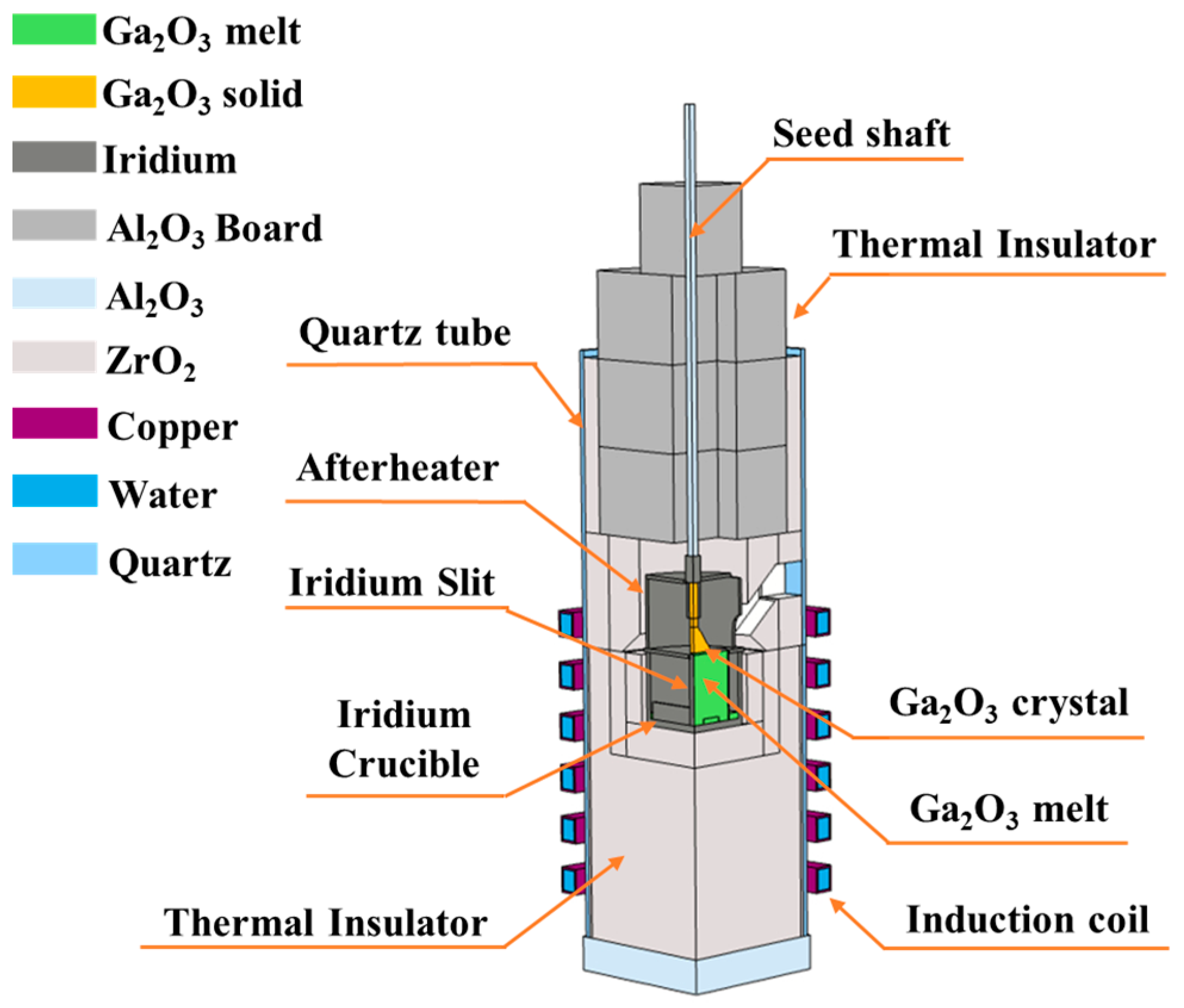
2.1. Multiphysics Modeling of the EFG System

A schematic of the induction-heating EFG system is shown in Figure 1. Considering the asymmetric shape of the EFG method, the growth model in the shouldering step was modeled as a three-dimensional one-quarter model with symmetrical xz plane and yz plane, as shown in Figure 1. The bottom of the iridium crucible was placed in the center of the induction coil, and the zirconia and alumina refractories were placed around the crucible. To analyze the change in the temperature distribution with and without an afterheater, an afterheater made of iridium with a thickness of 2 mm and a height of 40 mm with the same diameter as the crucible was modeled, as shown in Figure 1. View ports of 25 mm × 20 mm and 10 mm × 19 mm were considered for the zirconia refractory and the afterheater, respectively, for monitoring the process during growth. The operating frequency of the induction furnace was 11 kHz, and the temperature of the gallium oxide melt on the crystal-growth surface was simulated to be at least above the melting point of gallium oxide of ~1800 °C.
The finite element model for multiphysics simulation using tetrahedral elements is shown in Figure 2a. While the maximum size of the tetrahedral elements was set to 40 mm in the global modeling, the critical parts such as the solid–liquid interface of the 1.2 mm layer were meshed with finer tetrahedral elements with a mesh size of 0.1–10 mm to improve the accuracy of the calculation, as shown in Figure 2b,c. The temperature of the coil and the chamber wall was fixed to 30 °C since they were cooled with the water coolant in the real EFG system. Based on the finite element model, coupled multiphysics analyses combining electromagnetic field analysis, induction heating analysis, heat transfer analysis, and heat and mass transfer analysis were performed using COMSOL Multiphysics S/W packages.
In an induction growth furnace, the induced secondary current is formed at the hot zone, which causes Joule heating of the induction chamber. The electromagnetic field in the induction furnace is derived using the following equations [18].
× H = J
B = × A
E = j ω A
J = σ E + j ω D
where J, B, E, and H are the current density [A/m2], the flux density [T], the electric field strength [V/m], and the magnetic field strength [A/m], respectively. And j, ω, A, σ , and D are an imaginary unit, the angular frequency [rad/s], the magnetic-potential vector [V × S/m], the electrical conductivity [S/m], and the electric linear flux density [C/m2], respectively.
To analyze the heat transfer in the system, we used the equation below [19].
ρ C p · T = · k T + Q
where ρ is the density [kg/m3], Cp is the heat capacity [J/kg*K]; T is the temperature [K]; and Q is the additional heat transfer by convection or radiation.
Since the radiation is proportional to the power of temperature, the radiant heat transfer is particularly important at the high growing temperatures over 1800 °C in the crystal growth of gallium oxide. The radiant heat transfer was calculated using the equation below [19,20]:
G = G m J + F a m b σ T a m b 4
1 ε s G = J ε σ T
ε s G σ T 4 = n · ( k T )
For the fluid analysis of the gas flow inside the growth furnace, the fluid domains were divided into inner and outer zones with the boundary of refractories. Only the fluid inside the refractories was analyzed using the Navier–Stokes equation, while the fluid in the outer zone was not analyzed, and only the convective heat transfer coefficient was applied to the outer wall of the furnace. The flow in the gallium oxide melt was considered to be laminar, and no-slip conditions were applied to all solid walls:
ρ u t + u · u = p + τ + F g r a + F a m f
where ρ , u t , τ ,   p were the density [kg/m3], velocity change with time, viscous stress, and pressure [Pa]. And F g r a and F e m f were the gravity force density and electromagnetic force density, respectively [19,20].
The properties of the materials used in this multiphysics simulations and nomenclature are described in Table 1 and Nomenclature section, respectively.

2.2. Crystal Growth Experiments

Using an induction growth furnace with and without an afterheater shown in Figure 1, crystal growth was performed. Gallium oxide powder of 5N-grade (99.999%) and 0.5 mol% SnO2 powder were used as raw materials. The raw materials were placed in a 76 mm diameter iridium crucible and melted using RF induction heating at a frequency of ~11 kHz. The growth atmosphere was controlled at Ar:CO2 = 1:1 with a process pressure of 1.1 atm, and the seed crystals were mounted in a seed holder and fixed to a pulling shaft. The temperature of the lid was monitored through a viewport with a pyrometer, and the temperature at the bottom of the crucible was monitored through a thermocouple beneath the crucible. In the EFG method, the molten raw materials placed at the bottom of the crucible move to the top of the die through the capillary slit. By placing seed crystals on the fed melt, sheet-shaped crystal is grown by pulling the grown crystals. In this study, the pulling rate was set to 9.8 mm/h.
As a result, since the EFG method grows single crystals perpendicular to the growing face, single crystals oriented to [010] direction were obtained by growing along the [001] direction. The grown crystals were analyzed using polarization analysis, high-resolution X-ray diffraction (HR-XRD) (SmartLab, Rigaku, Tokyo, Japan), and micro-Raman analysis (UniDRON, Uni Nano Technology, Yongin, Republic of Korea).

3. Results and Discussion

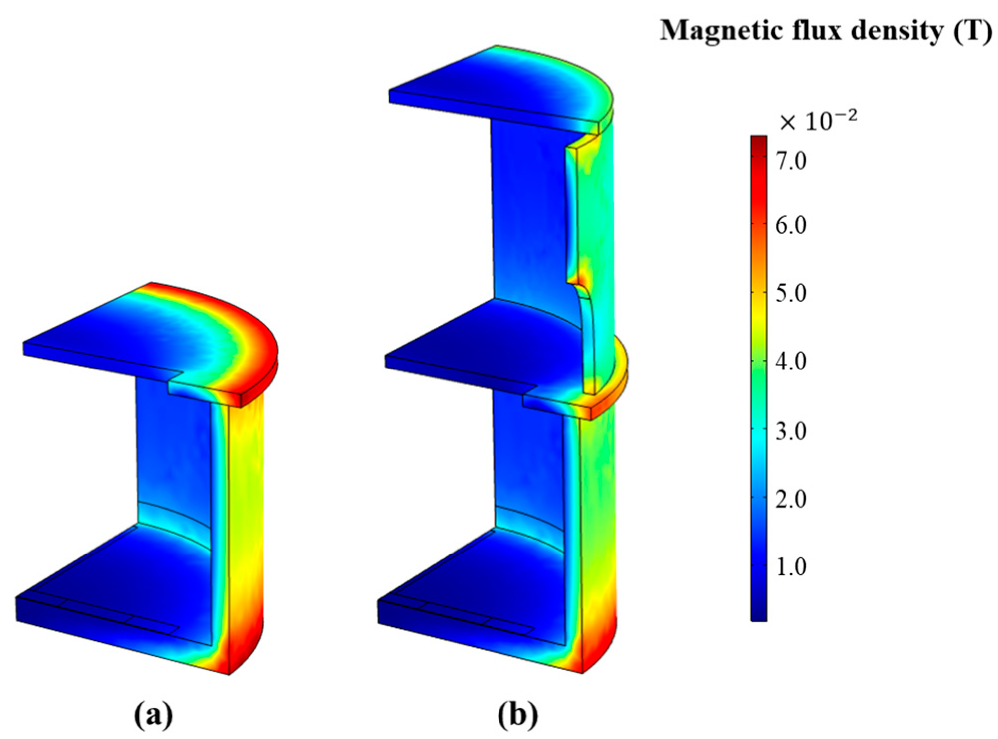
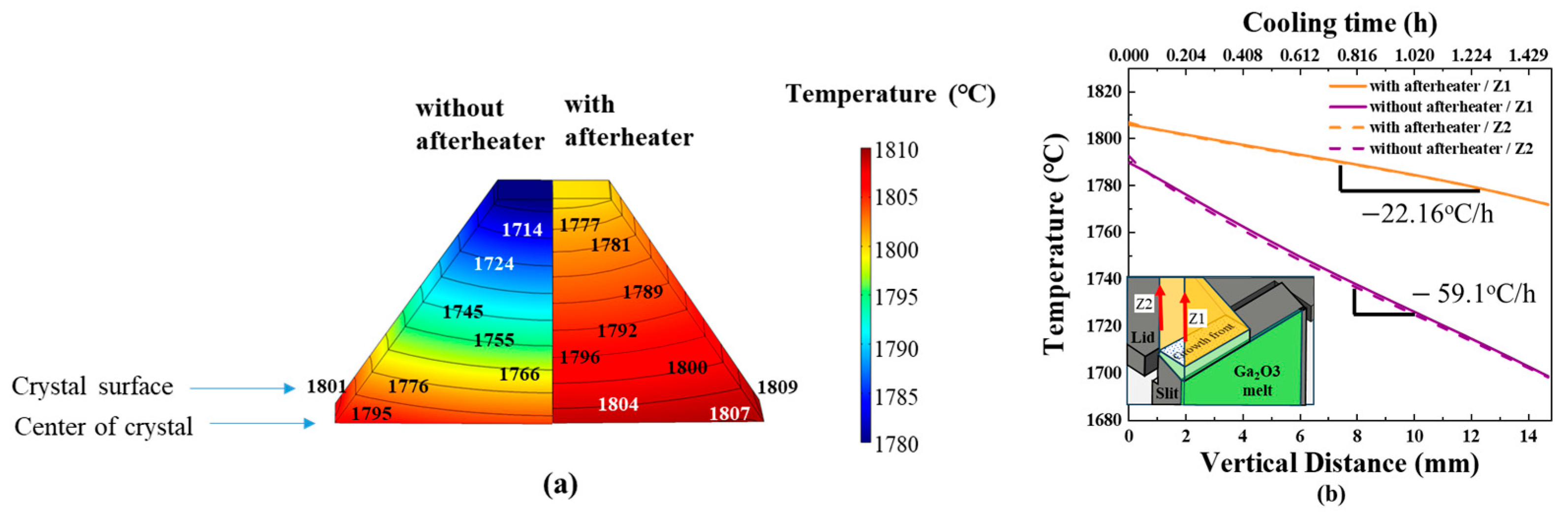
3.1. Model Validation and Temperature Distribution in the Reactor

Afterheaters have been used in the growth of oxide-based single crystals, such as sapphire, to control the temperature distribution on the growth surface and the cooling process of the post-growth crystal by creating the desired temperature distribution and heat flow in the induction furnace [14,22]. Recently, there have been experimental reports that the use of a properly dimensioned iridium afterheater in the EFG growth of gallium oxide greatly helps to optimize the process of gallium oxide single-crystal growth [23].
Table 2 shows the temperatures measured on the lid at the top of the crucible and beneath the bottom of the crucible during the crystal growth and the temperatures simulated with multiphysics models. The temperature difference between the top and the bottom of the crucible increased from 298 °C to 346 °C by adding the afterheater from the experimental measurements. From the simulations, the temperature difference between the two points increased from 308 °C to 332 °C. The errors in the temperature difference in the models without and with an afterheater between the experiment and the simulation were found to be 3.35% and 4.05%, respectively.
Since iridium is not reactive with gallium oxide, we adopted iridium as the material of the afterheater. The performance of the afterheater depends not only on the material but also on its position, size, and geometric shape. Figure 3a,b shows the electromagnetic flux density and temperature distribution in the global model without and with the afterheater, respectively. The electromagnetic flux densities especially in the crucible and active afterheater are shown in Figure 4a,b. The results showed that in both models, the magnetic field strongly reached the wall of the crucible, while the magnetic field was relatively weak inside the crucible. From these results, the crucibles and the afterheater are found to be properly heated by the electromagnetic induction effect. From this sense, it was confirmed that the afterheater acted as an “active” afterheater in this study. According to the temperature analysis shown in Figure 5, the maximum temperature of the outer wall of the crucible was found to be higher than 1970 °C for the basic model without an afterheater, and ~1911 °C for the model with an afterheater, indicating that the maximum temperature decreases by adding an afterheater to the reactor. It was interesting to note that the temperature gradient of the model with the afterheater was significantly smaller than that of the model without the afterheater. This confirmed that the afterheater applied in this study reduced the temperature gradient in the induction furnace through induction heat generation and radiation heat transfer.

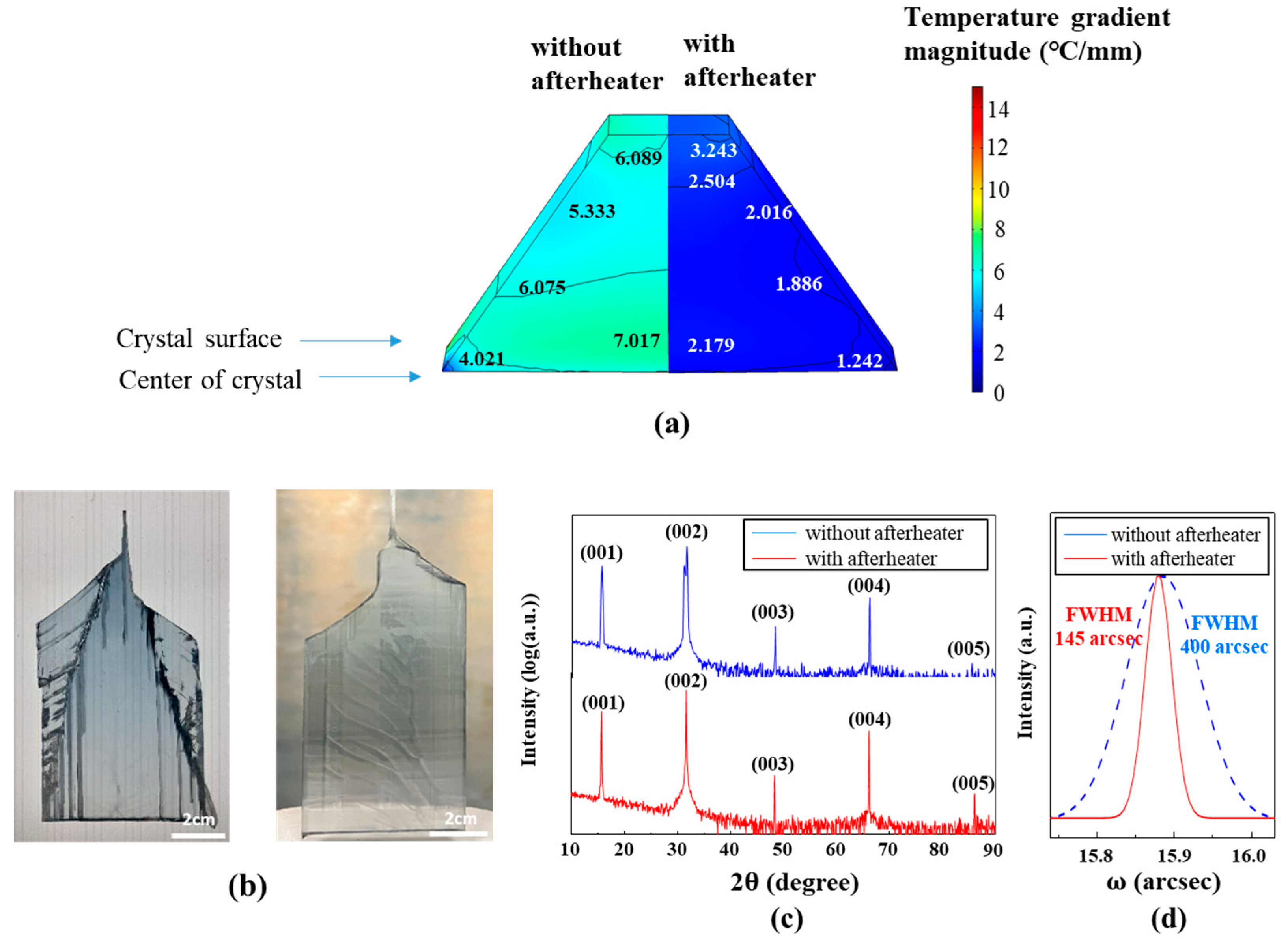
3.2. Temperature Distribution in the Crystallization

The temperature distribution and temperature gradient at the growth front shown in Figure 6a are shown in Figure 6b and 6c, respectively. As shown in Figure 6b, the temperature distribution at the growth front in both models showed higher temperatures at the edges of the crystal. The temperature difference between the center and the edge of the crystal was larger than 10 °C in the model without afterheater, however, the temperature difference was reduced to ~3 °C by adding afterheater to the reactor. The temperature gradients of the crystal-growth surface shown in Figure 6c were calculated to be 6~8 °C/mm in the model without afterheater and 2~3 °C/mm in the model with afterheater, showing a large difference of more than 2 times.
The local temperature gradient during crystallization eventually induces thermal stress, which causes various crystal degradation phenomena such as dislocation, phase transformation, defects, dendrite polycrystals, and cracks. Hence, minimizing the temperature gradient at the crystal-growth surface is essential to grow high-quality single crystals.
The temperature distribution of Figure 6b was shown as a graph of temperature distribution by predefined paths. From the graphs shown in Figure 7a,b, the uniformity of the growth temperature was evaluated along the predefined paths to show the effect of the afterheater. The temperature distributions along the paths to the direction perpendicular to the slit, paths x1 and x2, are shown in Figure 7a, while the temperature distributions by paths to the direction horizontal to the slit, paths y1 and y2, are shown in Figure 7b. Along the paths x2 and y2 on the outer surface facing the afterheater and crucible, the temperature was always higher than along the paths x1 and y1 inside the crystal. In particular, the deviation between the inner and outer crystal paths significantly decreased when the afterheater was applied, confirming that the radiant heat transfer of the afterheater reduced the temperature deviation in the crystal growth of gallium oxide.

3.3. Temperature Change of Grown Crystals near the Growth Temperature

The thermal conductivity of gallium oxide crystals ranges from 13.6 to 22.8 W/m-k, which is poor compared to other wide bandgap power semiconductor materials such as SiC (170 W/m-k), GaN (130 W/m-k), and diamond (2200 W/m-k), and is also poor compared to other single crystal materials such as silicon and sapphire grown by the CZ method or EFG method. Therefore, radiant heat transfer should play an important role in the heat transfer in the high-temperature processes growing Ga2O3 crystals.
In the above, it was assumed that an afterheater enhances radiant heat transfer to reduce the temperature difference at the growth surface during crystal growth. Since gallium oxide has poor thermal conductivity, however, the temperature distribution along the growing direction is required to be understood well. Figure 8a shows the temperature gradient in the crystal along the growing direction with and without the afterheater. Since the heat transfer of the simulation model was calculated based on the assumption of the steady state, the calculated temperature gradient of Figure 8a is the minimum value of the temperature gradient when the pulling rate of the grown crystals is sufficiently low enough to ignore the effect of pulling rate on the temperature distribution. In Figure 8a, the temperature of the grown crystals in the model with the afterheater was entirely higher in all regions than that without the afterheater. The temperature distribution inside and on the surface of the growth crystal was plotted along the growing direction as a function of vertical distance as shown in Figure 8b. Since the height of the grown crystal along the growing direction is determined using the pulling rate, the temperature distribution in the growth crystal solely depends on the hot-zone structure if the pulling rate is sufficiently low. Under steady-state simulation of this study, therefore, the temperature gradient of the grown crystals should be highly dependent on the radiant heat transfer considering the poor thermal conductivity of the gallium oxide.
Under the assumption of the steady state, the cooling time was obtained by dividing the x-axis of Figure 8b by the pulling rate of 9.8 mm/h. The cooling rate of the growth crystal under a steady state was then derived from the slope of the temperature distribution graph along the vertical in the grown crystal. As a result, the cooling rate of the grown crystal after growth near the growth temperature was found to be 59.1 °C/h in the model without the afterheater, while it was 22.16 °C/h in the model with the afterheater. From the critical resolved shear stress (CRSS) at the slip plane, the criterion of slip formation of crystals becomes low as the temperature increases, and the slip easily forms at high temperatures under very-low stress levels [24,25]. To minimize the thermal residual stress, therefore, the annealing process at high temperatures near the melting point is known to be effective. The afterheater applied in this study was found to reduce the cooling rate of the grown crystals under a steady state by nearly three times. The slow cooling rate under a steady state was estimated to derive thermal annealing effects during the crystal growing process to reduce residual stress of the grown crystal. Hence, the afterheater applied in this study was assumed to be effective in improving the crystal quality of gallium oxide.

3.4. Grown Results

Figure 9a shows the temperature gradient, the temperature difference divided by the unit length, in the grown crystal obtained from the simulations. Again, it was confirmed that the application of the afterheater significantly reduced the temperature gradient. The temperature gradient is closely related to the thermal stress and the crystal quality of crystals grown by the liquid-phase methods [26,27,28]. Hence, we analyzed the crystal quality of the experimentally grown crystals to compare with the temperature-gradient distribution.
Figure 9b shows the as-grown crystals with models with and without the afterheater. In the grown crystal without the afterheater, a clear polycrystalline region was observed at the shoulders of the crystals with remarkable longitudinal twins. However, no polycrystal or twin were found in the crystal grown with an afterheater.
The XRD measurements of Figure 9c were carried out for the crystals, indicating that all the grown crystals had single crystalline phases oriented to (001), both with and without the afterheater. The XRD rocking-curve analysis shown in Figure 9d shows 400 arcsec of full width at half-maximum (FWHM) value without the afterheater and 145 arcsec with the afterheater, indicating that a single crystal of good crystallinity with low residual stress was grown by adopting the afterheater.
In summary, the afterheater provided low-temperature deviation at the growth front during crystal growth, as shown in Figure 6c, and also provided an annealing effect retarding the cooling rate, as confirmed in Figure 8a,b. Hence, the use of the afterheater is suggested to be advantageous to growing crystals of high quality. Since Ga2O3 has poor thermal conductivity, the effect of the afterheater could be remarkable, especially in the crystal growth via the EFG method, in which slab-like crystals are grown. Since the performance of the afterheater is dependent on its position, size, material, and shape, however, the optimal design of the afterheater is recommended to produce bulk Ga2O3 crystals of commercial grade. Based on the understanding of the afterheater obtained in this study, further experimental study should be carried out to optimize the hot-zone design considering the crystal quality of the grown crystals in the near future.

4. Conclusions

A multiphysics simulation was used to evaluate the performance of an afterheater to enhance radiant heat transfer in the EFG process of gallium oxide crystal growth and compare it with experimental crystal growth results. The simulation results showed that the applied afterheater was effective in achieving good temperature distribution to grow gallium oxide single crystals at the growth front. The simulations also pointed out that the afterheater relieves the thermal stresses of the grown crystal by providing annealing effects near the growth temperatures during the growing process. Considering the poor thermal conductivity of gallium oxide, this study suggests that the use of the afterheater to activate radiant heat transfer should be considered to reach optimal growth conditions for gallium oxide crystals with good crystal quality.

Author Contributions

Conceptualization, S.-M.J.; methodology, S.-M.L. and S.-M.J.; software, S.-M.J. and W.-H.J.; validation, S.-M.C., W.-J.L., J.-K.K., S.-Y.B. and Y.-J.S.; formal analysis, S.-M.J. and W.-H.J.; investigation, S.-M.C., S.-Y.B. and Y.-J.S.; writing—original draft preparation, W.-H.J.; writing—review and editing, S.-H.K. and S.-M.J.; visualization, W.-H.J.; supervision, S.-H.K. and S.-M.J.; project administration, S.-Y.B.; All authors have read and agreed to the published version of the manuscript.

Funding

This research was supported by the Nano & Material Technology Development Program through the National Research Foundation of Korea (NRF), which is funded by the Ministry of Science and ICT (2021M3H4A3A01061782).

Data Availability Statement

The data presented in this study are available in the article.

Conflicts of Interest

Author J.-K.K. was employed by the company AXEL Co., Ltd. The remaining authors declare that the research was conducted in the absence of any commercial or financial relationships that could be construed as a potential conflict of interest.

Nomenclature

VariableDescription [Unit]VariableDescription [Unit]
ρ Density (kg m−3) C p Heat capacity (J (kg−1 K−1))
ε s Surface emissivity p Pressure difference (Pa)
σ Electrical conductivity (S m−1) Gradient operator
T Temperature (K) E Electric field intensity (V m−1)
· Divergence operator D Electric flux density (C m−2)
X Curl operator J Electric current density (A m−2)
H Magnetic field intensity (A m−1) j Imaginary unit
B Magnetic flux density (T) F a m b Ambient view factor
A Magnetic potential vector (V s m−1) F e m f Electromagnetic force density
ωAngular frequency (rad s−1) F g r a Gravity force density
GSurface irradiation (W m−2) T a m b Ambient temperature (K)
εRelative permittivity μ Dynamic viscosity (Pa s)
kThermal conductivity (W (m−1 K−1)) u Velocity vector (m s−1)
G m Mutual surface irradiation (W m−2) g Gravitational acceleration constant (m s−2)

References

  1. Pearton, S.J.; Yang, J.; Cary, P.H.; Ren, F.; Kim, J.; Tadjer, M.J.; Mastro, M.A. A review of Ga2O3 materials, processing, and devices. Appl. Phys. Rev. 2018, 5, 011301. [Google Scholar] [CrossRef]
  2. Higashiwaki, M.; Sasaki, K.; Kamimura, T.; Wong, M.H.; Krishnamurthy, D.; Kuramata, A.; Masui, T.; Yamakoshi, S. Depletion-mode Ga2O3 metal-oxide-semiconductor field-effect transistors on β-Ga2O3 (010) substrates and temperature dependence of their device characteristics. Appl. Phys. Lett. 2013, 103, 123511. [Google Scholar] [CrossRef]
  3. Wong, M.H.; Goto, K.; Murakami, H.; Kumagai, Y.; Higashiwaki, M. Current Aperture Vertical β-Ga2O3 MOSFETs Fabricated by N- and Si-Ion Implantation Doping. IEEE Electron Device Lett. 2019, 40, 431. [Google Scholar] [CrossRef]
  4. Higashiwaki, M.; Sasaki, K.; Kuramata, A.; Masui, T.; Yamakoshi, S. Gallium oxide (Ga2O3) metal-semiconductor field-effect transistors on single-crystal β-Ga2O3 (010) substrates. Appl. Phys. Lett. 2012, 100, 013504. [Google Scholar] [CrossRef]
  5. Higashiwaki, M. β-Ga2O3 material properties, growth technologies, and devices: A review. AAPPS Bulletin 2022, 32, 3. [Google Scholar] [CrossRef]
  6. Hoshikawa, K.; Kobayashi, T.; Matsuki, Y.; Ohba, E.; Kobayashi, T. 2-inch diameter (1 0 0) β-Ga2O3 crystal growth by the vertical Bridgman technique in a resistance heating furnace in ambient air. J. Cryst. Growth 2020, 545, 125724. [Google Scholar] [CrossRef]
  7. Hoshikawa, K.; Ohba, E.; Kobayashi, T.; Yanagisawa, J.; Miyagawa, C.; Nakamura, Y. Growth of β-Ga2O3 single crystals using vertical Bridgman method in ambient air. J. Cryst. Growth 2016, 447, 36. [Google Scholar] [CrossRef]
  8. Galazka, Z.; Uecker, R.; Irmscher, K.; Albrecht, M.; Klimm, D.; Pietsch, M.; Brützam, M.; Bertram, R.; Ganschow, S.; Fornari, R. Czochralski growth and characterization of β-Ga2O3 single crystals. Cryst. Res. Technol. 2010, 45, 1229–1236. [Google Scholar] [CrossRef]
  9. Galazka, Z. β-Ga2O3 for wide-bandgap electronics and optoelectronics. Semicond. Sci. Technol. 2018, 33, 113001. [Google Scholar] [CrossRef]
  10. Kuramata, A.; Koshi, K.; Watanabe, S.; Yamaoka, Y.; Masui, T.; Yamakoshi, S. Bulk crystal growth of Ga2O3. In Proceedings of the Oxide-Based Materials and Devices IX, San Francisco, CA, USA, 27 January–1 February 2018; Volume 10533, pp. 9–14. [Google Scholar] [CrossRef]
  11. Kuramata, A.; Koshi, K.; Watanabe, S.; Yamaoka, Y.; Masui, T.; Yamakoshi, S. High-quality β-Ga2O3 single crystals grown by edge-defined film-fed growth. Jpn. J. Appl. Phys. 2016, 55 Pt 1, 1202A2. [Google Scholar] [CrossRef]
  12. Kamada, K.; Sasaki, R.; Tomida, T.; Takahashi, I.; Yoshino, M.; Horiai, T.; Murakami, R.; Kochurikhin, V.; Shoji, Y.; Kakimoto, K.; et al. Crucible-Free Growth of Bulk b-Ga2O3 Single-Crystal Scintillator under Oxidizing Atmosphere. Crystals 2023, 13, 921. [Google Scholar] [CrossRef]
  13. Tadjer, M.J.; Lyons, J.L.; Nepal, N.; Freitas, J.A.; Koehler, A.D.; Foster, G.M. Editors’ Choice—Review—Theory and Characterization of Doping and Defects in β-Ga2O3. ECS J. Solid State Sci. Technol. 2019, 8, Q3187. [Google Scholar] [CrossRef]
  14. Tavakoli, M.H.; Samavat, F.; Baiepour, M. Influence of active afterheater on the induction heating process in oxide Czochralski systems. Cryst. Res. Technol. 2008, 43, 145–151. [Google Scholar] [CrossRef]
  15. Roy, A.; Zhang, H.; Prasad, V.; Mackintosh, B.; Ouellette, M.; Kalejs, J.P. Growth of large diameter silicon tube by EFG technique: Modeling and experiment. J. Cryst. Growth 2001, 230, 224–231. [Google Scholar] [CrossRef]
  16. Lasloudji, I.; Mokhtari, F.; Nehari, A.; Goget, G.A.; Lebbou, K. Experimental and numerical effects of active afterheater addition on the growth of langatate (La3Ga5.5Ta0.5O14) crystals by the Czochralski method. CrystEngComm 2018, 20, 1110–1115. [Google Scholar] [CrossRef]
  17. Galazka, Z. Growth of bulk β-Ga2O3 single crystals by the Czochralski method. J. Appl. Phys. 2022, 131, 031103. [Google Scholar] [CrossRef]
  18. Ha, M.-T.; Yu, Y.-J.; Shin, Y.-J.; Bae, S.-Y.; Lee, M.-H.; Kim, C.-J.; Jeong, S.-M. Flow modification enhancing the growth rate in top seeded solution growth of SiC crystals. RSC Adv. 2019, 9, 26327. [Google Scholar] [CrossRef]
  19. Ha, M.-T.; Lich, L.V.; Shin, Y.-J.; Bae, S.-Y.; Lee, M.-H.; Jeong, S.-M. Improvement of SiC Crystal Growth Rate and Uniformity via Top-Seeded Solution Growth under External Static Magnetic Field: A Numerical Investigation. Materials 2020, 13, 651. [Google Scholar] [CrossRef]
  20. Shin, Y.-J.; Lim, S.-M.; Jeong, W.-H.; Cho, S.-H.; Choi, M.-H.; Lee, W.-J.; Jeong, S.-M.; Bae, S.-Y. Growth of (100) β-Ga2O3 single crystal by controlling the capillary behaviors in EFG system. Jpn. J. Appl. Phys. 2023, 62, SF1022. [Google Scholar] [CrossRef]
  21. Le, C.; Li, Z.; Mu, W.; Jia, Z.; Liu, L. 3D numerical design of the thermal field before seeding in an edge-defined film-fed growth system for β-Ga2O3 ribbon crystals. J. Cryst. Growth 2019, 506, 83. [Google Scholar] [CrossRef]
  22. Tavakoli, M.H.; Omid, S.; Mohammadi-Manesh, E. Influence of active afterheater on the fluid dynamics and heat transfer during Czochralski growth of oxide single crystals. CrystEngComm 2011, 13, 5088–5093. [Google Scholar] [CrossRef]
  23. Amodeo, J.; Merkel, S.; Tromas, C.; Carrez, P.; Korte-Kerzel, S.; Cordier, P.; Chevalier, J. Dislocations and Plastic Deformation in MgO Crystals: A Review. Crystals 2018, 8, 240. [Google Scholar] [CrossRef]
  24. Fu, B.; Jian, G.; Mu, W.; Li, Y.; Wang, H.; Jia, Z.; Li, Y.; Long, S.; Shi, Y.; Tao, X. Crystal growth and design of Sn-doped β-Ga2O3: Morphology, defect and property studies of cylindrical crystal by EFG. J. Alloys Comp. 2022, 896, 162830. [Google Scholar] [CrossRef]
  25. Richter, J. The Influence of Temperature on Slip Behaviour of Molybdenum Single Crystals Deformed in Tension in the Range from 293 to 573 °K. II. Slip Geometry and Structure of Slip Bands. Phys. Status Solidi b 1971, 46, 203–215. [Google Scholar] [CrossRef]
  26. Billing, E. Some defects in crystals grown from the melt—I. Defects caused by thermal stresses. Proc. R. Soc. Lond. 1956, 235, 37–55. [Google Scholar] [CrossRef]
  27. Ren, S.; Tan, Y.; Jiang, D.; Li, P.; Li, J. Effect of temperature gradient on the diffusion layer thickness of impurities during directional solidification process. Mater. Sci. Semicond. Process. 2018, 74, 102–108. [Google Scholar] [CrossRef]
  28. He, G.; Gao, X.; Han, Y.; Li, J.; Liu, J. Effect of temperature gradient on microstructure and properties of GaSb crystals grown with Bridgman method. Mater. Res. Express. 2020, 7, 055902. [Google Scholar] [CrossRef]
Figure 1. Three-dimensional one-quarter model of EFG reactor growing Ga2O3 crystal at the shouldering step with symmetrical xz plane and yz plane.
Crystals 13 01591 g001
Figure 2. (a) Finite element model of EGF reactor meshed with tetrahedral elements meshed model for EFG grower. The meshed model within the red rectangular box is zoomed in and shown in the following figures: (b) Meshed model magnified in the reactor without afterheater. (c) Meshed model magnified in the reactor with afterheater.
Crystals 13 01591 g002
Figure 3. Magnetic flux density and temperature distribution of EFG reactor obtained in simulation models (a) without afterheater and (b) with afterheater.
Crystals 13 01591 g003
Figure 4. (a) Magnetic flux density in the crucible obtained from the simulation without an afterheater and (b) magnetic flux density in the crucible and the afterheater obtained from the simulation with an afterheater.
Crystals 13 01591 g004
Figure 5. Temperature distribution of EFG systems (Left: from simulation without an afterheater, Right: from simulation with an afterheater).
Crystals 13 01591 g005
Figure 6. (a) Schematic showing results obtained from simulations with/without an afterheater at the growth front, (b) Temperature distribution, (c) Temperature gradient magnitude.
Crystals 13 01591 g006
Figure 7. (a) Temperature deviation at the growth front along paths of x1 and x2 with/without an afterheater (b) Temperature deviation at the growth front along paths of y1 and y2 with/without an afterheater.
Crystals 13 01591 g007
Figure 8. (a) Temperature distribution in the grown crystals at the shouldering step with/without an afterheater. (b) Temperature deviation along the growing direction along paths of z1 and z2.
Crystals 13 01591 g008
Figure 9. (a) Temperature gradient in the grown crystals at shouldering step with/without an afterheater. (b) Grown crystals in the hot-zone (right) with and without (left) and an afterheater. (c) XRD data of the grown crystals with/without an afterheater. (d) X-ray rocking-curve data for the grown crystals with/without an afterheater.
Crystals 13 01591 g009
Table 1. Material properties used in the simulations [21].
Properties Ga 2 O 3   ( s ,   m )Iridium (s)Zirconia (s)Al2O3 (s)
Density [kg m−3]5700 (s), 4837 ( m )22,40060403965
Thermal conductivity [W/m K]11 (s), 17 ( m )1472.1435
Heat capacity [J/kg K]560 (s), 800 ( m )130419730
Dynamic viscosity [kg/m s]0.1 ( m )---
Melting point [degC]1800---
Surface tension [N/m]0.65 ( m )---
Surface emissivity0 (s), 0.3 ( m )0.50.40.75
Refractive index1.9 (s)---
Absorption coefficient [m−1]400 (s)---
Electrical conductivity [S m−1]5000 (s, m )1.8868 × 10⁷--
Table 2. Comparative data between experiments and simulations for model validation.
➀ Top Edge of Crucible Lid Temperature (°C) ➁ Crucible Bottom Temperature (°C) Temperature Difference (➀–➁) (°C) Error
ExperimentalSimulations ExperimentalSimulations ExperimentalSimulations
Afterheater O18111815 14651483 346332 4.05%
Afterheater X18181820 15201522 298308 3.35%
Disclaimer/Publisher’s Note: The statements, opinions and data contained in all publications are solely those of the individual author(s) and contributor(s) and not of MDPI and/or the editor(s). MDPI and/or the editor(s) disclaim responsibility for any injury to people or property resulting from any ideas, methods, instructions or products referred to in the content.

