
A Fibrous Perovskite Nanomaterial with Exsolved Ni-Cu Metal Nanoparticles as an Effective Composite Catalyst for External Steam Reforming of Liquid Alcohols
Abstract
:
1. Introduction
2. Materials and Methods
2.1. Materials Preparation
2.2. Characterization
2.3. Catalytic Test
2.4. SOFC Test
3. Results
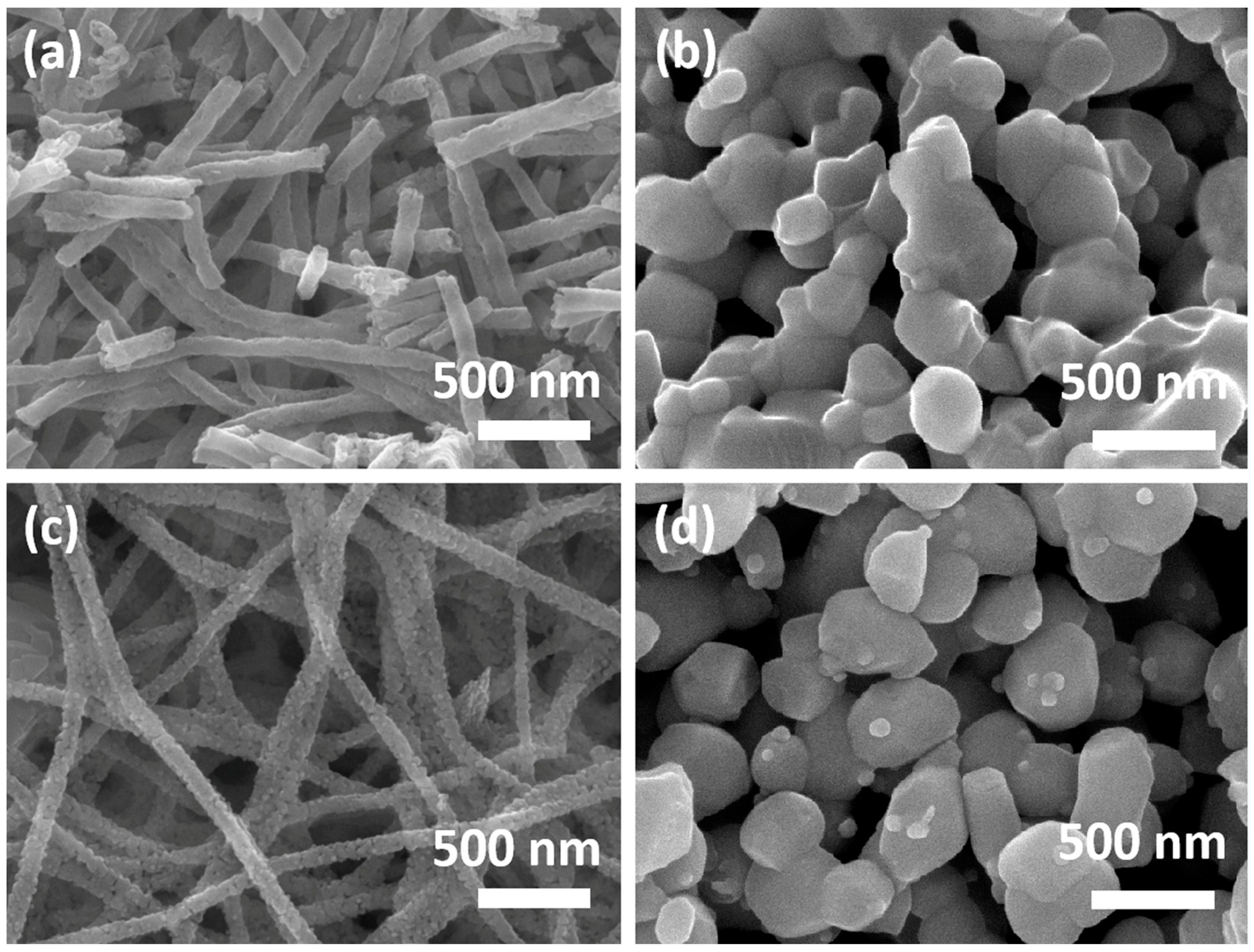
3.1. Materials Characteristics
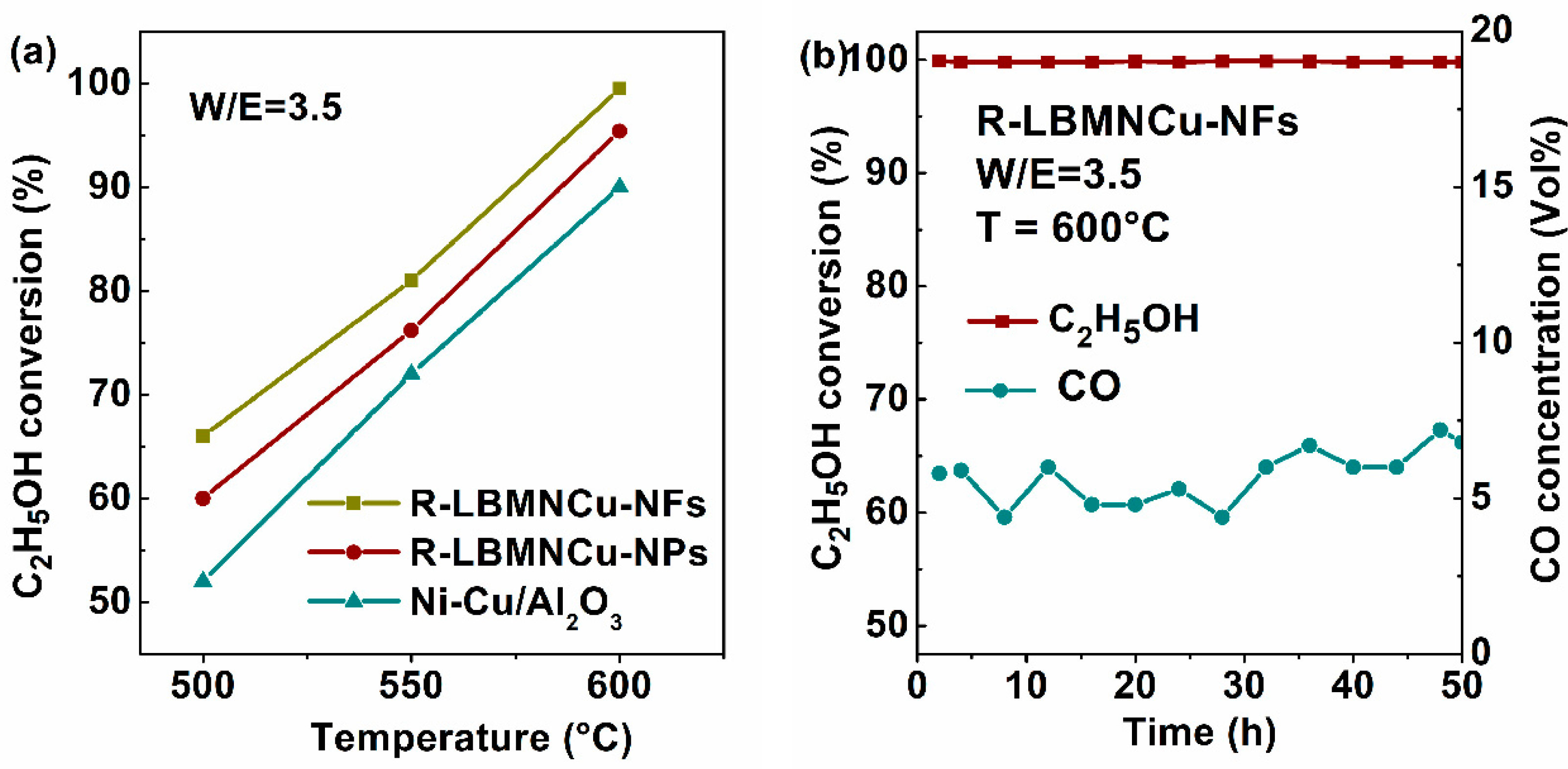
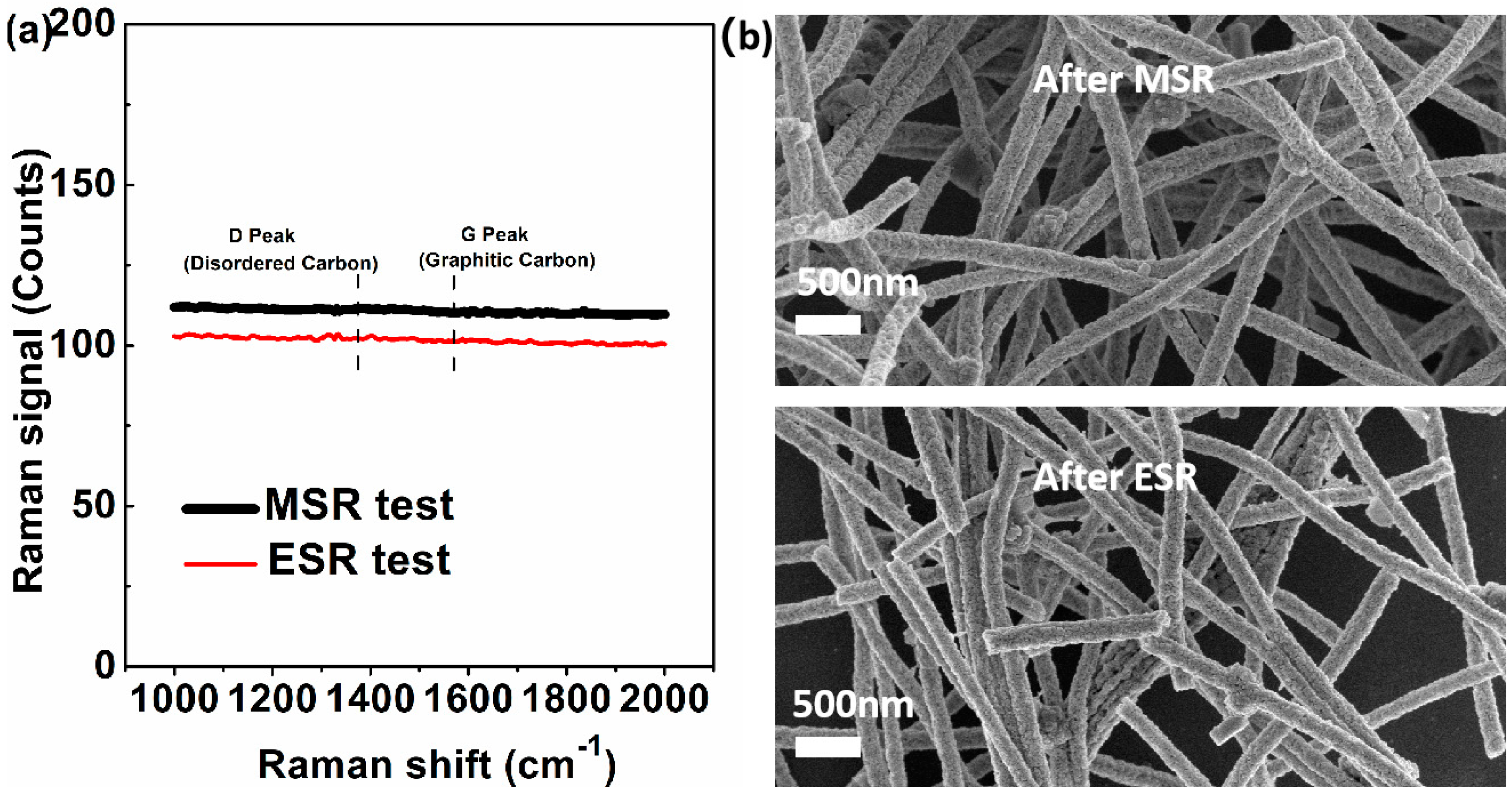
3.2. MSR Test
3.3. ESR Test
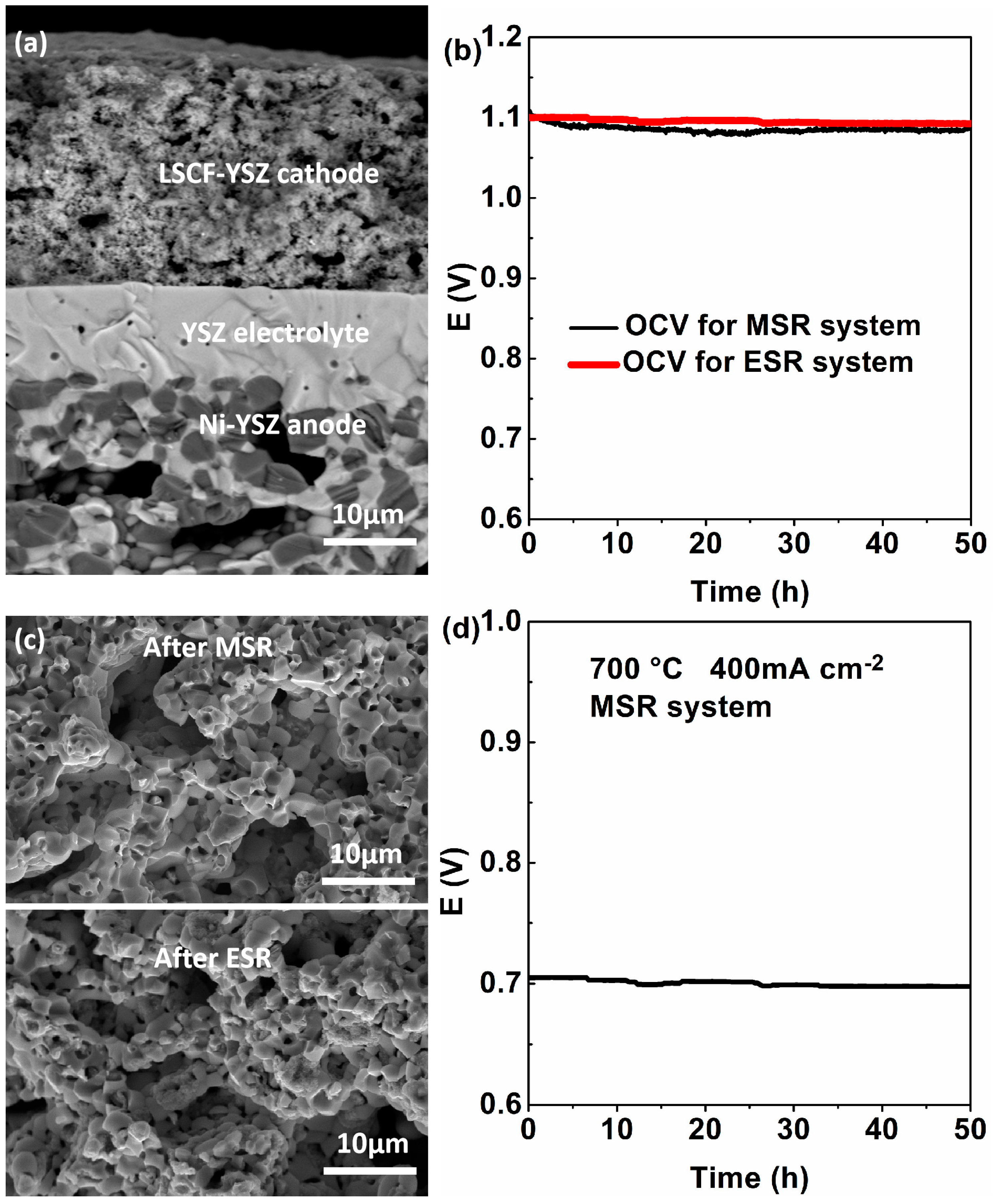
3.4. Application
4. Conclusions
Supplementary Materials
Author Contributions
Funding
Data Availability Statement
Conflicts of Interest
References
- Krishnakumar, T.; Kiruthiga, A.; Jozwiak, E.; Moulaee, K.; Neri, G. Development of ZnO-based sensors for fuel cell cars equipped with ethanol steam-reformer for on board hydrogen production. Ceram. Int. 2020, 46, 17076–17084. [Google Scholar] [CrossRef]
- Shen, Q.; Jiang, Y.; Xia, F.; Wang, B.; Lv, X.; Ye, W.; Yang, G. Hydrogen production by Co-based bimetallic nano-catalysts and their performance in methane steam reforming. Petrol. Sci. Technol. 2020, 38, 618–625. [Google Scholar] [CrossRef]
- Haryanto, A.; Fernando, S.; Murali, N.; Adhikari, S. Current status of hydrogen production techniques by steam reforming of ethanol: A review. Energy Fuels 2005, 19, 2098. [Google Scholar] [CrossRef]
- Mateos-Pedrero, C.; Azenha, C.; DA, P.T.; Sousa, J.M.; Mendes, A. The influence of the support composition on the physicochemical and catalytic properties of Cu catalysts supported on Zirconia-Alumina for methanol steam reforming. Appl. Catal. B-Environ. 2020, 277, 119243. [Google Scholar] [CrossRef]
- Li, H.; Tian, H.; Chen, S.; Sun, Z.; Liu, T.; Liu, R.; Assabumrungrat, S.; Saupsor, J.; Mu, R.; Pei, C.; et al. Sorption enhanced steam reforming of methanol for high-purity hydrogen production over Cu-MgO/Al2O3 bifunctional catalysts. Appl. Catal. B-Environ. 2020, 276, 119052. [Google Scholar] [CrossRef]
- Pratihar, S.K.; Dassharma, A.; Maiti, H.S. Properties of Ni/YSZ porous cermets prepared by electroless coating technique for SOFC anode application. J. Mater. Sci. 2007, 42, 7220–7226. [Google Scholar] [CrossRef]
- Hong, S.; Yang, H.; Lim, Y.; Prinz, F.B.; Kim, Y.-B. Grain-Controlled Gadolinia-Doped Ceria (GDC) Functional Layer for Interface Reaction Enhanced Low-Temperature Solid Oxide Fuel Cells. ACS Appl. Mater. Interfaces 2019, 11, 41338–41346. [Google Scholar] [CrossRef]
- He, L.; Hu, S.; Jiang, L.; Liao, G.; Zhang, L.; Han, H.; Chen, X.; Wang, Y.; Xu, K.; Su, S.; et al. Co-production of hydrogen and carbon nanotubes from the decomposition/reforming of biomass- derived organics over Ni/α-Al2O3 catalyst: Performance of different compounds. Fuel 2017, 210, 307–314. [Google Scholar] [CrossRef]
- Wu, C.; Williams, P.T. Hydrogen production from steam reforming of ethanol with nano-Ni/SiO2 catalysts prepared at different Ni to citric acid ratios using a sol−gel method. Appl. Catal. B-Environ. 2011, 102, 251–259. [Google Scholar] [CrossRef]
- Chang, C.C.; Chang, C.T.; Chiang, S.J.; Liaw, B.J.; Chen, Y.Z. Steam reforming of methanol over Cu/ZnO/CeO2/ZrO2/Al2O3 catalysts. Appl. Catal. A-Gen. 2009, 358, 7–12. [Google Scholar]
- Yang, Q.; Zhou, C.; Ni, J.; Guan, X. Methane dry reforming in a coking- and sintering-free liquid alloy-salt catalytic system. Sustain. Energy Fuels 2020, 4, 2768–2774. [Google Scholar] [CrossRef]
- Mateos-Pedrero, C.; Silva, H.; Tanaka, D.; Liguori, S.; Iulianelli, A.; Basile, A.; Mendes, A. CuO/ZnO catalysts for methanol steam reforming: The role of the support polarity ratio and surface area. Appl. Catal. B-Environ. 2015, 174–175, 67–76. [Google Scholar] [CrossRef]
- Saracco, G.; Scibilia, G.; Iannibello, A. Methane Combustion on Mg-Doped LaCrO3 Perovskite Catalysts. Appl. Catal. B Environ. 1996, 8, 229–244. [Google Scholar] [CrossRef]
- Xu, X.; Su, C.; Shao, Z. Fundamental Understanding and Application of Ba0.5Sr0.5Co0.8Fe0.2O3-δ Perovskite in Energy Storage and Conversion: Past, Present, and Future. Energy Fuels 2021, 35, 13585–13609. [Google Scholar] [CrossRef]
- Rivas, I.; Alvarez, J.; Pietri, E.; Pérez-Zurita, M.; Goldwasser, M. Perovskite-type oxides in methane dry reforming: Effect of their incorporation into a mesoporous SBA-15 silica-host. Catal. Today 2010, 149, 388–393. [Google Scholar] [CrossRef]
- Kwon, O.; Sengodan, S.; Kim, K.; Kim, G.; Jeong, H.Y.; Shin, J.; Ju, Y.W.; Han, J.W.; Kim, G. Exsolution trends and co-segregation aspects of self-grown catalyst nanoparticles in perovskites. Nat. Commun. 2017, 8, 15967. [Google Scholar] [CrossRef]
- Nair, M.; Kaliaguine, S. Structured catalysts for dry reforming of methane. New J. Chem. 2016, 40, 4049–4060. [Google Scholar] [CrossRef]
- Wei, T.; Jia, L.; Luo, J.-L.; Chi, B.; Pu, J.; Li, J. CO2 dry reforming of CH4 with Sr and Ni co-doped LaCrO3 perovskite catalysts. Appl. Surf. Sci. 2019, 506, 144699. [Google Scholar] [CrossRef]
- Neagu, D.; Oh, T.S.; Miller, D.N.; Ménard, H.; Bukhari, S.M.; Gamble, S.R.; Gorte, R.J.; Vohs, J.M.; Irvine, J.T. Nano- socketed nick el particles with en hanced coking r esistance grown in si tu by redox ex solution. Nat. Commun. 2015, 6, 8120. [Google Scholar] [CrossRef] [PubMed]
- Neagu, D.; Tsekouras, G.; Miller, D.N.; Irvine, J.T. In situ growth of nanoparticles through control of non-stoichiometry. Nat. Chem. 2013, 5, 916–923. [Google Scholar] [CrossRef] [PubMed]
- Jin, J.; Wu, L.; Huang, S.; Yan, M.; Wang, H.; Chen, L.; Hasan, T.; Li, Y.; Su, B. Hierarchy Design in Metal Oxides as Anodes for Advanced Lithium-Ion Batteries. Small Methods 2018, 2, 1800171. [Google Scholar] [CrossRef]
- Xu, J.; Wang, Z.; Xu, D.; Meng, F.; Zhang, X. 3D ordered macroporous LaFeO3 as efficient electrocatalyst for Li-O2 batteries with enhanced rate capability and cyclic performance. Energy Environ. Sci. 2014, 7, 2213–2219. [Google Scholar] [CrossRef]
- Wang, Z.; Zou, L.; Guo, S.; Sun, M.; Chen, Y.; Chi, B.; Pu, J.; Li, J. Porous double-doped perovskite La0.6Ca0.4Fe0.8Ni0.2O3 nanotubes as highly efficient bifunctional catalysts for lithium-oxygen batteries. J. Power Sources 2020, 468, 228362. [Google Scholar] [CrossRef]
- Zhang, X.; Gong, Y.; Li, S.; Sun, C. Porous perovskite La0.6Sr0.4Co0.8Mn0.2O3 nanofibers loaded with RuO2 nanosheets as an efficient and durable bifunctional catalyst for rechargeable Li-O2 batteries. ACS Catal. 2017, 7, 7737–7747. [Google Scholar] [CrossRef]
- Dresselhaus, M.; Dresselhaus, G.; Saito, R.; Jorio, A. Raman spectroscopy of carbon nanotubes. Phys. Rep. 2005, 409, 47–99. [Google Scholar] [CrossRef]


Disclaimer/Publisher’s Note: The statements, opinions and data contained in all publications are solely those of the individual author(s) and contributor(s) and not of MDPI and/or the editor(s). MDPI and/or the editor(s) disclaim responsibility for any injury to people or property resulting from any ideas, methods, instructions or products referred to in the content. |
© 2023 by the authors. Licensee MDPI, Basel, Switzerland. This article is an open access article distributed under the terms and conditions of the Creative Commons Attribution (CC BY) license (https://creativecommons.org/licenses/by/4.0/).
Share and Cite
Wei, T.; Wang, J.; Jia, Y.; Harimoto, T. A Fibrous Perovskite Nanomaterial with Exsolved Ni-Cu Metal Nanoparticles as an Effective Composite Catalyst for External Steam Reforming of Liquid Alcohols. Crystals 2023, 13, 1594. https://doi.org/10.3390/cryst13111594
Wei T, Wang J, Jia Y, Harimoto T. A Fibrous Perovskite Nanomaterial with Exsolved Ni-Cu Metal Nanoparticles as an Effective Composite Catalyst for External Steam Reforming of Liquid Alcohols. Crystals. 2023; 13(11):1594. https://doi.org/10.3390/cryst13111594
Chicago/Turabian StyleWei, Tong, Juan Wang, Yangbo Jia, and Tatsukuni Harimoto. 2023. "A Fibrous Perovskite Nanomaterial with Exsolved Ni-Cu Metal Nanoparticles as an Effective Composite Catalyst for External Steam Reforming of Liquid Alcohols" Crystals 13, no. 11: 1594. https://doi.org/10.3390/cryst13111594