Abstract
In this paper, the effects and the mechanisms of melt superheating treatment (MST) on a directionally solidified alloy were investigated. The mass loss rate of the superalloy becomes severe as the MST temperature rises. The chromium, tantalum, and hafnium are the primary evaporation elements during MST. As the MST temperature increases from 1500 to 1600 °C, the secondary dendrite arm spacing is reduced by 13.3%, and the average size of γ′ particles are reduced by 11.5% and 18.2% in the dendrite core and inter-dendritic area, respectively. The content of oxygen and nitrogen gradually reduces with the increase in the MST temperature. However, the sulfur content is not significantly affected by the MST temperature. The essential cause of γ′ phases transition is supposed to be the MST-induced changes in solute distribution and the decomposition of atomic clusters. In addition, the nitrides and Ti (N, C)-type carbides are continuously dispersed as the MST temperature increases, which promotes the removal of nitrogen impurities.
1. Introduction
The development of aero-engines and gas turbines requires higher inlet temperatures at the front end of the turbine to increase thrust and efficiency. Accordingly, higher demands are put forward for superalloys and manufacturing processes. At present, directionally solidified superalloys are widely used in the manufacture of modern aircraft engines, such as turbine blades and guide blades [1,2,3].
The harsh operating conditions of aero-engines impose more stringent requirements on the performance of directionally solidified superalloy parts. Studies have shown that changes in the parameters of the alloy casting process also affect the properties of the alloy [4,5,6]. Since the beginning of the 20th century, the superheating treatment of alloy melts has been found to be effective in reducing element segregation, decreasing dendrite arm spacing, increasing the amounts of precipitation phases, and improving the size and distribution of precipitation phases. As a result, it helps enhance the properties of alloys [7,8,9].
Recent studies have shown that MST (melt superheating treatment) can not only optimize the microstructure of the alloy, but also improve the purity of the alloy [10,11,12]. Pei and Tian [10] studied the variation of nitrogen content in a nickel-based alloy after a melt superheat treatment at different temperatures. Under the same casting temperature and mold shell temperature, increasing the MST temperature can promote the denitrification of the alloy. The experimental values are well matched with the theoretical predictions. For alloys requiring a liquid–solid phase transition, the state of the alloy in the liquid phase can have a significant impact on the subsequent solidification structure and solidification process [13,14,15,16]. Therefore, the melt superheating temperature is a vital factor affecting the properties of the superalloy, which will affect the metallurgical quality and even eliminate the heritability of the alloy structure. Zhang et al. [17] investigated the effect of the melt characteristics on the mechanical behavior of the DD3 nickel-based single-crystal superalloy. The results show that the superheating treatment can improve the stress rupture performance under 1040 °C/190 Mpa. The segregation of titanium, molybdenum, and tungsten in dendrite areas is reduced greatly under MST treatment, and, thus, the stability of the γ′ rafts increases significantly.
In conclusion, metallurgical quality and service performance can be effectively improved by MST of superalloys [18,19]. However, there are few relevant studies on the aspect of MST on the purification behavior of superalloys. MST is an economical and simple way to treat alloys. It is of great significance to study the effect of MST treatment on the removal of impurity elements. Therefore, the impact of MST on the microstructure and purification behavior of a superalloy prepared by directional solidification was studied in this paper, and the influencing mechanisms were also revealed.
2. Materials and Methods
2.1. Alloys and Pretreatment
The alloy studied in this paper is a directionally solidified superalloy. It exhibits exceptional comprehensive properties and remarkable high-temperature creep resistance, rendering it suitable for the fabrication of gas turbine rotor blades operating at temperatures below 1000 °C as well as other high-temperature components functioning below 1050 °C. The compositions of the raw material are shown in Table 1, which are prepared by the traditional vacuum induction melting (VIM) process.

Table 1.
The content of alloy elements in the raw material (wt.%).
The raw material was cut into three groups using wire cutting equipment and used for the melting experiment. The grinding prototype is used to remove the oxide skin and the wire cutting contamination layer from the surface of the raw material, so as to prevent the introduction of external impurity elements and other pollutants during the experiment. The obtained samples were placed in alcohol for ultrasonic cleaning for 15 min and thoroughly dried in a drying oven at 70 °C. After being weighed on an electronic scale, the raw materials were placed in alumina crucibles for melting.
2.2. Melt Superheating Treatment
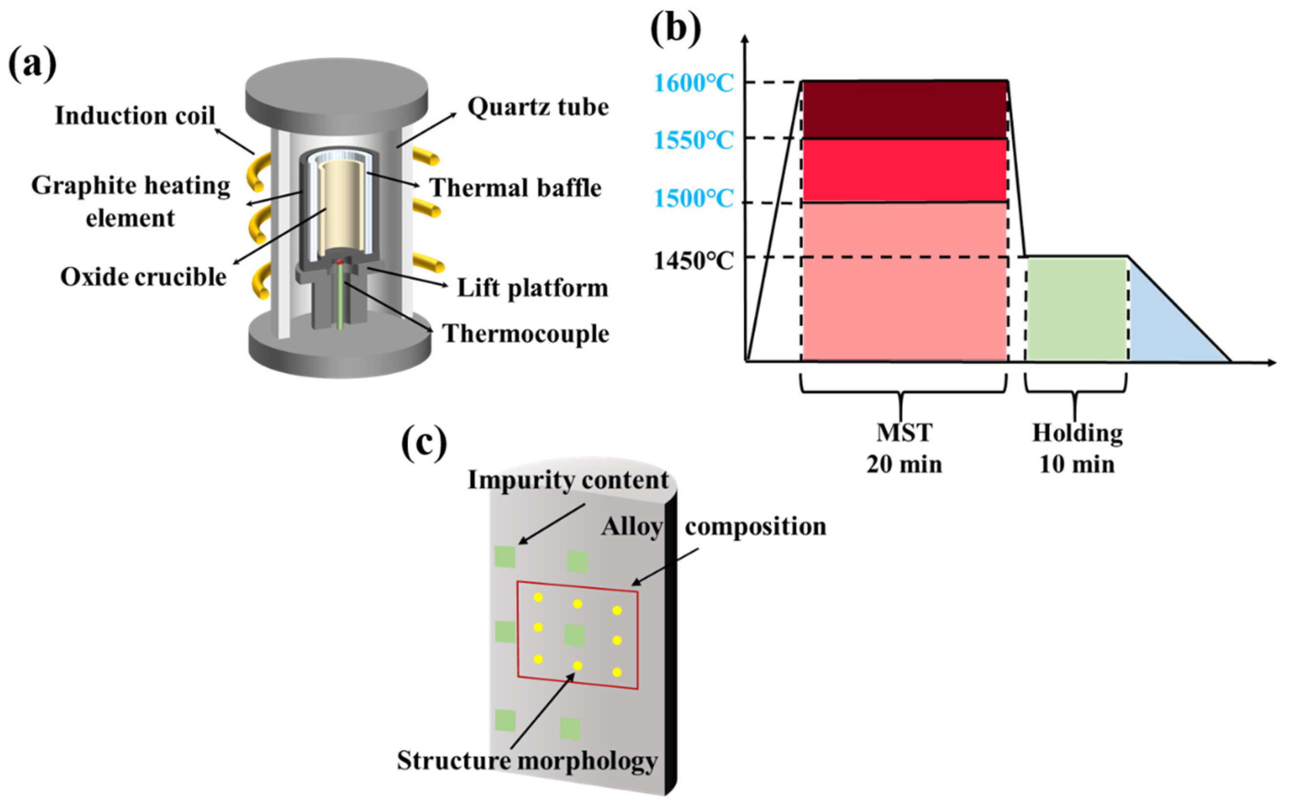
Figure 1a is a schematic diagram of the melting equipment in this experiment. The equipment mainly consists of electrical control system, vacuum system, melting system, and water-cooling system. The equipment is heated by high-frequency power supply, and the temperature in the melting process can be adjusted by controlling the heating power. The vacuum system can maintain the ultimate vacuum of the melting process at 4 × 10⁻² Pa. Figure 1c shows the flow chart of MST by vacuum induction melting. The melting point of the DZ125 alloy is 1295–1377 °C. To investigate the impact of MST on the microstructure and purity of the DZ125 alloy, MST temperatures that are at least 50 °C higher than the maximum temperature used in traditional vacuum induction melting processes for DZ125 alloy have been selected, namely, 1500 °C, 1550 °C, and 1600 °C. The alloy raw materials were individually heated by the melting system from room temperature to a set superheating temperature and retained for 20 min. Then, the vacuum induction melting temperature was reduced to 1450 °C and kept for 10 min. Subsequently, the induction coil was slowly pulled upwards by 20 cm at a speed of 3 μm/s, until the underside of the induction coil was placed above the upper part of the ingot. During the slow raising of the induction coil, the power of the electronic control system gradually dropped to zero. Until the ingots were completely solidified, the argon valve and the vacuum valve were closed. When the temperature was reduced to about 200 °C, the ingots were taken out for subsequent testing.
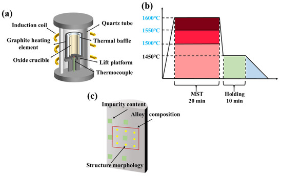
Figure 1.
The schematic diagram of (a) vacuum induction melting equipment; (b) the process flow of MST; (c) the sampling positions of different characterization methods.
2.3. Materials Characterization
The ingots obtained by the MST experiments were weighed with an electronic balance. The electrical discharge machining was used to cut the ingot into two parts along the height direction. One part of the ingots was used to characterize the macrostructure, while the other part was used to detect the composition, purity, and microstructure of the alloy. The samples for macrostructure observation were ground and polished, followed by etching in a solution composed of 20 g CuSO4·5 H2O + 5 mL H2SO4 + 100 mL HCl + 80 mL H2O. The macrostructures were then obtained using the DS-1630 S4-type HD scanner. The macrostructures were then rendered employing the Photoshop 2018 software. The sampling for composition analysis was performed at the position marked by the red frame in Figure 1c. The dimension of the samples was 15 × 15 × 10 mm3, in which a circular region with diameter of 10 mm was used to detect the average alloy composition by X-ray fluorescence spectrometer (XRF, Axios, PANalytical B.V., Almelo, The Netherlands). The surfaces of the samples were ground and polished, and then ultrasonic cleaned with deionized water before detection.
The yellow dots in Figure 1c represent the positions where the secondary dendrite arm spacing was measured with metallographic microscopy (OM, Axioscope 5, ZEISS Oberkochen, Germany). The measurement of dendrite spacing was carried out by selection of the evenly spaced secondary dendrites from the metallographic photos. The length of more than ten consecutive dendrites was subsequently measured, employing the Image-Pro Plus 6.0 analysis software. According to this method, the average secondary dendrite arm spacing of ten different locations were measured. Similarly, the size and distribution of γ′ particles in the alloy were captured using the scanning electron microscope (SEM, SU5000, HITACHI, Tokyo, Japan). The commercial Photoshop software was used to render the γ′ particles in inter-dendritic region and dendrite cores with different colors. The average size of γ′ particles were then measured using the above-mentioned Image-Pro analysis software.
Lastly, for the purpose of characterizing the purity of the MST-prepared ingots, specimen rods with dimensions of φ 5 × 5 mm were prepared by electrical discharge machining at the location marked by the green area in Figure 1c. The impurity contents of different MST ingots were tested by the oxygen and nitrogen analyzer (TC-436 AR, ELTRA, Frankfurt, Germany). An infrared carbon and sulfur analyzer (CS-3000G, NCS, Beijing, China) was used to measure the sulfur content with the accuracy of 0.0001 wt.%.
3. Results and Discussion
3.1. Effect of MST on the Volatilization Behavior of Alloy Elements
Based on the mass difference before and after vacuum induction melting, it is possible to deduce the mass loss rate of the alloys subjected to MST at different temperatures. The mass loss Δm is given in Equation (1), while the mass loss rate ζ after the MST can be determined using Equation (2), which is described as:
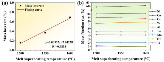
Figure 2.
(a) Mass loss rate and (b) element contents of alloys treated by different MST (melt superheating treatment) temperatures.
The compositions of the three groups of ingots subjected to MST are shown in Table 2 and Figure 2b. As can be seen from Table 2, the mass fractions of chromium, tantalum, and hafnium in the alloy decrease after MST. The mass loss of chromium, tantalum, and hafnium becomes more severe with the increase in MST temperature. The mass fraction of Ni increases with the MST temperature; however, the concentration of other elements does not vary significantly. The evaporation loss of alloy elements, especially Cr, is much greater than that of the base element with the increase in MST temperature, which results in an increase in the mass fraction of nickel. As the MST temperature increases to 1600 °C, the mass fraction of chromium decreases to 8.85 wt.%, which decreases by 4.9% compared with the raw material. In addition, the content of Ta and Hf were reduced by 4.3% and 1.6%, respectively, after the melt superheat treatment at 1600 °C, in comparison with the raw material. Therefore, Cr, Ta, and Hf are the main volatile elements in the MST process. However, since the elements are within the standard composition range after MST, there is no need to regulate the alloy composition.
Table 2.
Composition of three groups of DZ125 ingots after MST (melt superheating treatment) (wt.%).
3.2. Effect of MST on the Macrostructures and Microstructures of the Alloy
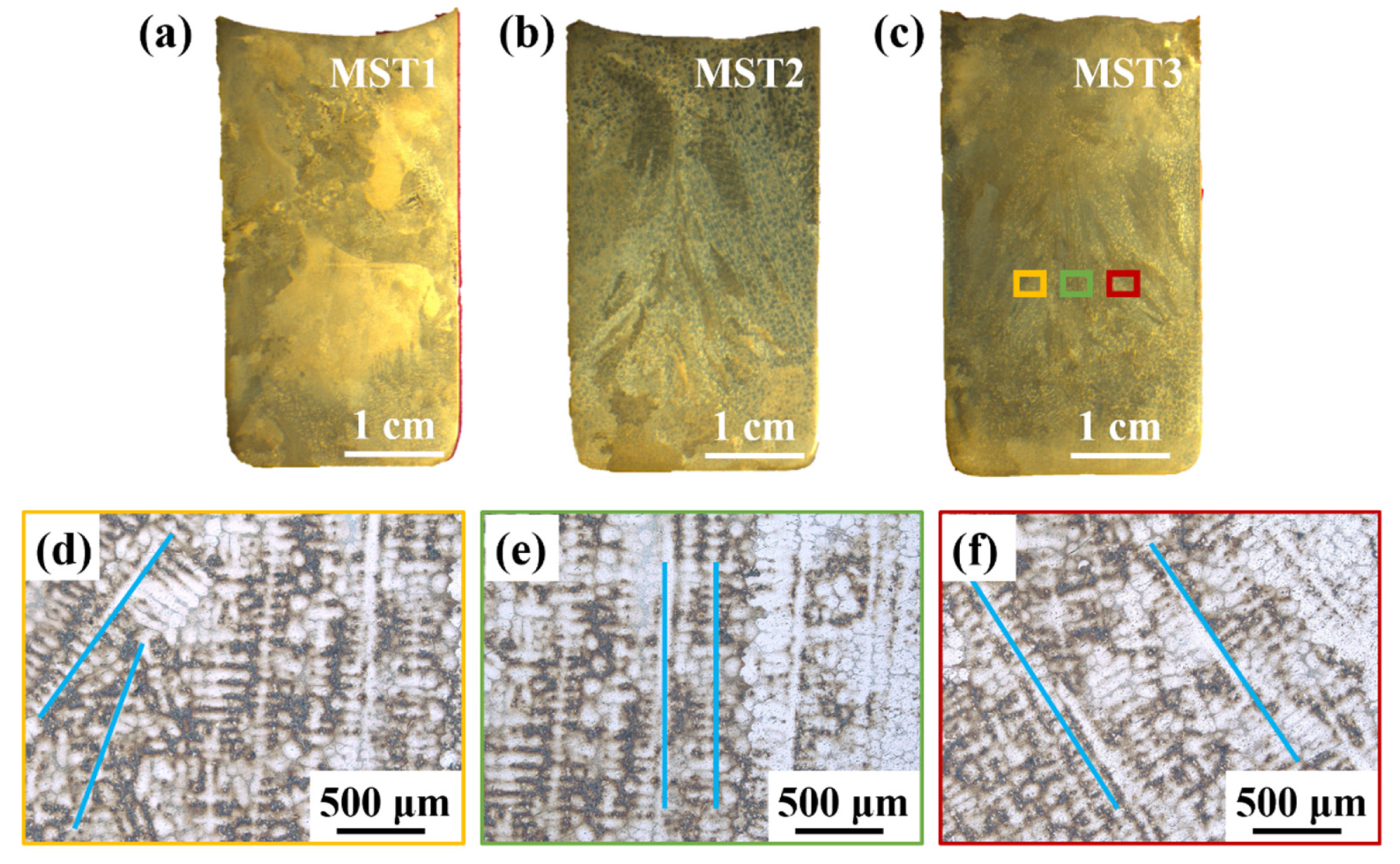
Figure 3a–c is the macroscopic cross-sectional view of ingots processed at different MST temperatures. It the obvious columnar grains caused by directional solidification can be seen. The columnar grains in the MST3 ingot in Figure 3c is enlarged to obtain the dendrite morphology, which is shown in Figure 3d–f. In the center of the ingot (green area), the dendrite grows in a straight line. However, the edge position of the ingot (yellow and red areas) grows diagonally, and the growth directions on both sides of the ingot are symmetrical. This is due to the bidirectional temperature gradient generated by the vacuum induction melting furnace during MST. Firstly, the alternating current generated by the induction coil generates an alternating magnetic field in the coil, and further generate eddy current on the graphite crucible placed at the center of the coil. During the continuous energization of the induction coil, the graphite crucible will also continue to generate eddy current, and then the crucible continues to generate Joule heat. The heat is then transmitted to the raw material to melt the raw material. Therefore, the crucible edge is at a higher temperature relative to the center of the alloy melt during the melting process. As a result, the alloy melt near the edge of the crucible solidifies preferentially. Secondly, when directional solidification is carried out after the melt thermal field is stable, the induction coil is kept at the previous power to pull up at a certain speed, so that the melt forms a top–down temperature gradient, which is conducive to the solidification of the ingot along the direction vertically upward from the bottom of the crucible and the formation of columnar crystals until the ingot is completely solidified.

Figure 3.
The macroscopic morphology of the ingots processed with different MST temperatures and locally enlarged dendrite structure: (a–c) the macrostructures of the ingot cross-sections prepared with parameters of MST1–MST3; (d–f) the enlarged dendrite structure of the yellow, green, and red areas in (c).
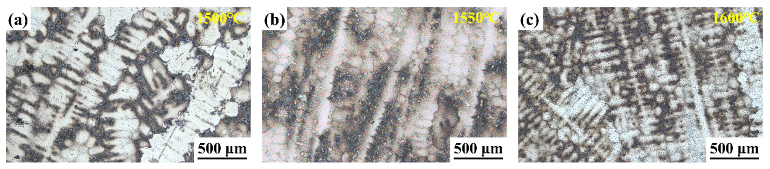
Figure 4 displays the dendritic morphology of ingots after MST with three different temperatures. With the rise in MST temperature, the dendritic structure of the alloy is gradually refined. The secondary dendrite arm spacing is a key indicator of the solidification structure of the superalloy. With the reduction in the secondary dendrite arm spacing, it is conducive to reduce the degree of segregation, reduce or even eliminate the solidification defects such as shrinkage, and shorten the homogenization time of heat treatment, so the characteristics of superalloy are also improved. Figure 5 shows the secondary dendrite arm spacing of ingots after MST with different temperatures. The secondary dendrite arm spacing of the alloy tends to reduce with increasing the MST temperature. The average secondary dendrite arm spacing decreased from 78.3 μm to 67.9 μm as the temperature increased from 1500 °C to 1600 °C, showing a decrease of 13.3%. The experimental results show that MST has a positive effect on reducing the secondary dendrite arm spacing of superalloys. The temperature interval for non-equilibrium crystallization gradually decreases as the MST temperature increases. Therefore, the average secondary dendrite arm spacing of the alloy reduces with higher MST temperature. On the basis of the Kurz–Fisher model, the local solidification time is the primary factor that affects the spacing of secondary dendrite arms, which can be expressed as:
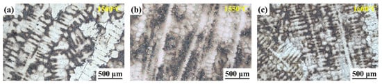
Figure 4.
The dendrite morphology of alloys after (a) 1500 °C, (b) 1550°C, (c) 1600 °C MST.
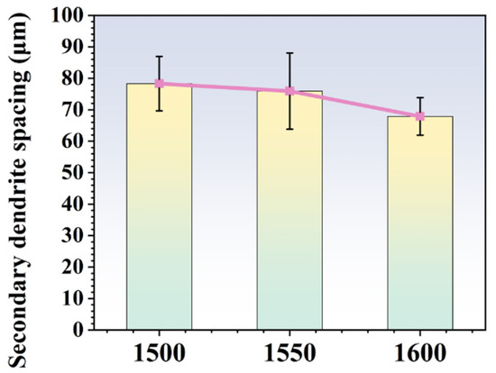
Figure 5.
The secondary dendrite spacing of the alloys prepared by different MST temperature.
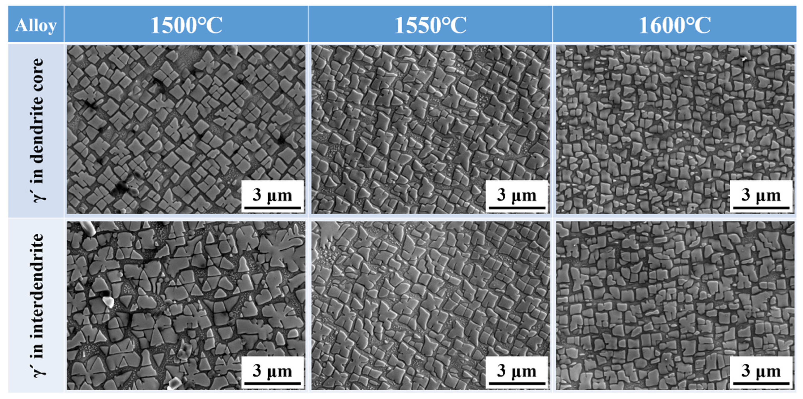
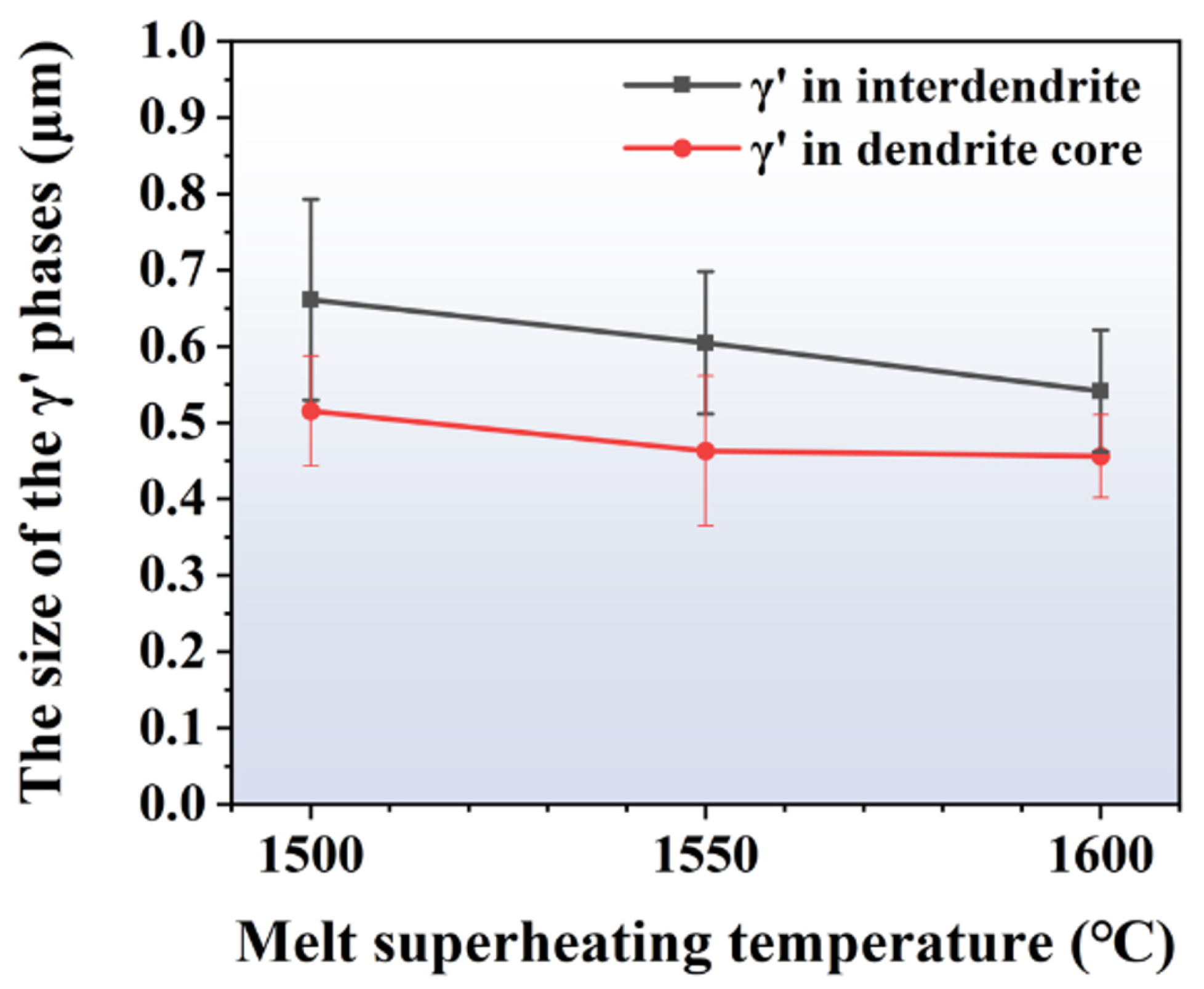
Figure 6 presents the morphology of γ′ particles in the inter-dendritic region and dendrite cores of the alloy processed with different MST temperatures. As the MST temperature grows from 1500 °C to 1600 °C, the morphology of the γ′ phases becomes more regular. However, it is evident from the figure that the size of the precipitates is not uniform. There is a large number of precipitates in the gap between the large-sized precipitates. At 1600 °C, the small-sized γ′ phases in the gap tends to grow. This ensures that the range of the maximum and minimum precipitated phase sizes is narrowed, and the size of the γ′ phases is more uniform. The sizes of γ′ particles in different ingots are calculated, which are given in Figure 7. It can be seen that the γ′ particle size in the dendritic core and inter-dendritic area show a decreasing trend with increasing MST temperature. Furthermore, the size of precipitates in the dendritic core region is significantly smaller than that in the inter-dendrites.
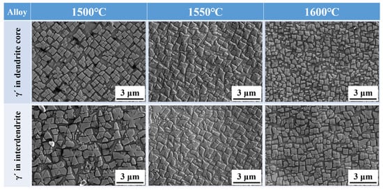
Figure 6.
γ′ morphologies in the dendrite core and inter-dendritic areas of alloys prepared by different MST temperatures.

Figure 7.
The size of γ′ phases at the dendrite core and inter-dendrite areas of the alloys prepared by different MST temperatures.
The size of the precipitates in the dendrite cores and inter-dendritic regions shows minimum values of 0.52 μm and 0.66 μm when the MST temperature is 1500 °C. When the MST temperature reaches 1600 °C, these two values will reduce to 0.46 μm and 0.54 μm, which are reduced by 11.5% and 18.2%, respectively. It is worth noting that the size difference of γ′ phases between the dendritic core and inter-dendritic region gradually decreases with increasing MST temperature. The smallest size difference and the highest degree of homogenization were observed at an MST temperature of 1600 °C.
The underlying cause of the variation in the γ′ phase should be the MST-induced changes in solute distribution and the decomposition of atomic clusters. The alloy undergoes a diffusive deconvoluted phase transition during solidification to form γ phase and γ′ precipitates. Suppose the volume of γ′ phases is , and the area of phase boundary is . The change in free energy during the phase transition is:
The γ′ particles are spherical when they are formed from the matrix. Consequently, their volume can be approximated as , and the area of phase boundary can be determined as . The above Equation (4) can be expressed as:
The critical radius for nucleation of γ′ and the critical nucleation work can be obtained by deriving the r in (6) when setting it equal to zero:
In the formula, and denote the variation in chemical free enthalpy and strain energy due to the formation of γ′ particles per unit volume. is the free energy per unit area of the phase interface between the γ phase and γ′ particles. During MST, the temperature gradient is constant at the solidification rate. The variations in γ′ phase morphology and size are apparently attributed to the MST-induced changes in melt structure.
In this study, the Ni3A1-type intermediate-range-ordered atomic group in the alloy disappeared after MST at different temperatures. During the solidification process, the Ni3A1-type intermediate-range-ordered atomic group reappears, while their structure and composition are altered. As a result, the formation elements of the Ni3A1-type γ′ phases become more uniform, leading to difficulties in the formation of the solute-poor element region and the solute-rich element region in supersaturated γ phases. Consequently, the temperature of formation of the γ′ phases reduces and the undercooling degree ∆T grows after the alloy melt experiences superheating treatment. Because is proportional to the supercooling degree ∆T, the increase in ∆T also leads to the increase in Therefore, the value of critical nucleation work and critical radius decreases, and the rate for nucleation of γ′ precipitates increases. As a result, the γ′ precipitates will be smaller with the increasing MST temperature [4,20].
Figure 8 shows the effect of MST temperature on the eutectic structure and carbides. The light gray areas in the figure are the eutectic microstructure, and the bright white carbides are distributed in a grid pattern in the dendritic gap. The γ/γ′ eutectic and carbides morphology of the ingots treated at different temperatures were not obviously distinct, and were all sunflower-like. The only difference is that the area of eutectic structure tends to decrease as the MST temperature increases. This is mainly because the number of eutectic structures depends on the solidification temperature range. With the increase in MST temperature, the temperature range for non-equilibrium crystallization gradually decreases. The width of the mushy zone is also shortened, so the number of eutectic structures will be reduced.
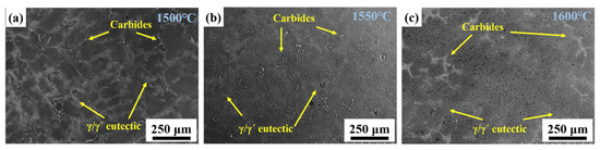
Figure 8.
The morphologies of γ/γ′ eutectic and carbides in the alloys prepared with different MST temperatures: (a) 1500 °C, (b) 1600 °C, (c) 1700 °C.
3.3. Effect of MST on Removal of Gas Impurities in Superalloy
The oxygen, nitrogen, and sulfur contents after various MST processes were calculated by averaging the number of impurities at different locations in the ingots, which are shown in Figure 9. The content of oxygen and nitrogen gradually decreased with the increase in the MST temperature. The minima appear at 1600 °C, which are 4.3 ppmw and 4.4 ppmw. At 1500 °C, the concentration decreased by 44.2% and 74.1% compared to values of 7.7 ppmw and 17.0 ppmw, respectively. However, the sulfur content is not significantly affected by the MST temperature. The sulfur concentration declines and then gradually increases as the MST temperature increases. The sulfur content in the ingot is basically stable at about 3 ppmw. In general, the MST is effective for the removal of nitrogen impurities, and not so effective for the removal of oxygen and sulfur impurities.
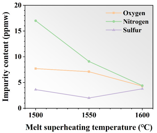
Figure 9.
The contents of oxygen, nitrogen, and sulfur impurities in DZ125 alloy before and after MST.
During the metallurgical process, the melt tends to inhale impurity gases and form various inclusions. Therefore, it is necessary to select a suitable metallurgical process to achieve the index of the superalloy. In techniques such as vacuum induction melting, the removal of dissolved impurities from the alloy matrix is usually facilitated by a higher vacuum condition. The O is the most active impurity element in superalloys, which can easily form oxide inclusions. Therefore, the high vacuum mainly facilitates the removal of N impurities. The dissolution reactions of nitrogen are shown in Equation (9).
The solid solubility of N [wt.% N] adheres to Sievert’s law in theory:
where kN indicates the equilibrium constant, PN2 denotes the gas partial pressure, and fN is the activity coefficient of N. The standard free energy for the solid solution of nitrogen is given by:
From , then derive:
Therefore, the theoretical solubility of nitrogen can be expressed by incorporating Equations (10) and (12):
The activity coefficient fN can be expressed as:
where wj is the mass fraction of element j, and and are the first and second order interaction parameters between nitrogen and element j, respectively. It has been reported by Yasushi Haruna et al. that the activity coefficient of nitrogen in Ni-based superalloys depends not only on the content of alloy elements, but also on the melt temperature [21]. The temperature modification factors for the calculation of activity coefficients were obtained according to the nitrogen solubility in five Ni-based superalloys [22]. Accordingly, Equation (14) can be modified as follows after consideration of the effect of temperature:
The interaction parameters between the major elements and nitrogen impurities can reference the values for pure nickel and iron alloy melts at 1600 °C, as listed in Table 3 [23,24,25,26,27,28]. The effect of MST temperature and vacuum on nitrogen solubility are derived from Equations (13) and (15), as seen in Figure 10. With the increase in MST temperature, the theoretical solid solubility of nitrogen increases slightly. That effect relative to vacuum is not significant. The theoretical solid solubility of nitrogen declines sharply with the decrease in vacuum in the melting chamber. The vacuum of the melting chamber in this study is about 0.5 Pa (purple line), so the actual amount of nitrogen impurity in the alloy is plotted in Figure 10. From the graph, it can be noted that the actual amount of nitrogen impurity is higher than the theoretical calculation value. With the increase in MST temperature, the actual value is closer to the theoretical calculation value. It fully indicates that the removal of nitrogen impurities in the superalloy melt is not only affected by the vacuum, but also by the MST temperature.
Table 3.
Interaction parameters between major elements and nitrogen impurities at 1600 °C.
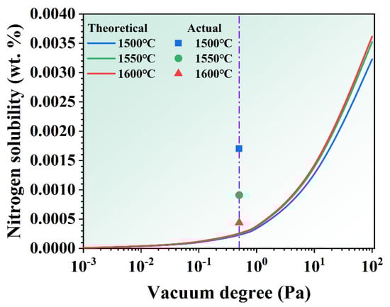
Figure 10.
The theoretical nitrogen solubility of the alloys treated by different vacuum degree and MST temperature.
Figure 11 illustrates the mass transmission process of nitrogen impurities during vacuum induction melting. The nitrogen removal process can be classified into five steps [29,30,31]: (1) [N] is transferred from the alloy melt to the boundary layer of the liquid by convective migration; (2) [N] is transferred to the liquid–gas interface through the boundary layer of the liquid phase by convection or diffusion; (3) the gas atoms in the liquid–gas interface combine with each other to form gas molecules; (4) the generated N2 is subjected to diffusive mass transmission in the boundary layer of gas phase; and (5) N2 transfers from the gas phase boundary layer to the gas phase, and is eventually sucked away.
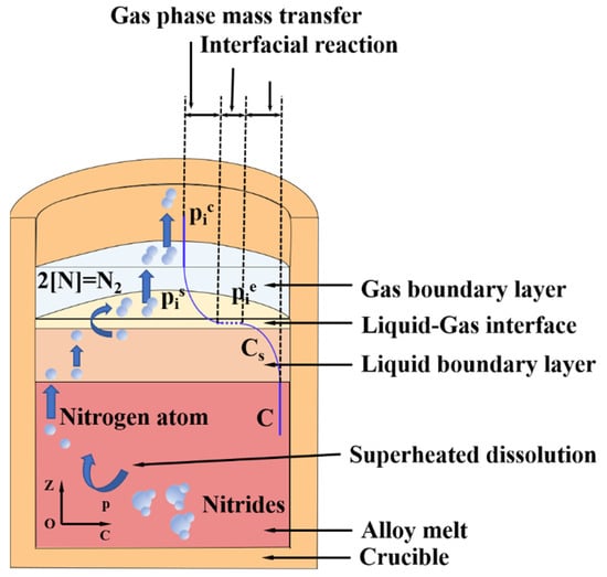
Figure 11.
Schematic diagram of the mass transmission process of nitrogen impurities in superalloy melt.
In the process of vacuum induction melting, the electromagnetic induction coil is heated to generate an alternating magnetic field, which further produces an eddy current on the graphite crucible placed at the center of the coil. Finally, the alloy melt undergoes strong melt flow, so step (1) is not the control step of nitrogen mass transfer. With the increase in vacuum, the mass transfer coefficient of gas phase will also increase significantly. Under the action of vacuum system, the mass transfer coefficient of N2 in the gas phase is much greater than that in the liquid phase and the gas formation reaction at the gas–liquid interface. Therefore, step (5) will not be the control step limiting the denitrification process. The mass transmission coefficient of step (4) is two orders of magnitude higher than that of step (3). Therefore, the control step of nitrogen removal may be step (2), step (3), or their combined action.
When the MST temperature is low, the denitrification reaction of the alloy melt cannot be carried out effectively, even if the vacuum is high. This is mainly because there are a large number of nitrogen-containing refractory particles in superalloy, such as Ti (N, C), TiN, HfN, and so on. When superalloys are heated and melted, their melt structure produces a change from ordered to disordered. When the superalloy is just melted, the inclusion clusters and carbide-based refractory particles cannot be effectively melted. Only at higher MST temperature, these nitrogen-containing refractory particles melt into the alloy melt. Then the reaction (9) can continue to move to the left and produce N2 to be discharged into the vacuum environment. At this time, the denitrification rate is controlled by the gas formation reaction at the gas–liquid interface and the process of mass transmission from the melt to the gas–liquid interface. With the increase in MST temperature, the nitrides and Ti (N, C)-type carbides are continuously dispersed, and the alloy melt becomes more uniform, which promotes the removal of nitrogen impurities. Therefore, the actual amount of nitrogen impurity in the superalloy tends to be consistent with the theoretically calculated nitrogen solid solubility.
4. Conclusions
In this work, the effect of melt superheating by vacuum induction melting on the composition, microstructure, and impurity content of a directionally solidified superalloy were investigated. The major findings are summarized below:
- The mass loss rate increases with the increase in the MST temperature. The chromium, tantalum, and hafnium are the main evaporating elements during the MST;
- With the increase in MST temperature, the dendrite structure is gradually refined. The secondary dendrite arm spacing can be reduced from 78.3 μm to 67.9 μm when the MST temperature increases from 1500 °C to 1600 °C;
- The refining of γ′ precipitates in the inter-dendritic area and dendrite cores occurs with the increase in MST temperature. The γ′ particles in the inter-dendritic area and dendrite cores show a minimum size of 0.54 μm and 0.46 μm when the MST temperature is 1600 °C;
- The underlying cause of the variation in the γ′ phases should be the MST-induced changes in solute distribution and the decomposition of atomic clusters;
- The content of oxygen and nitrogen gradually decreased with the growth of the MST temperature. There are the lowest values at 1600 °C, which are 4.3 ppmw and 4.4 ppmw, respectively. However, the sulfur content is not significantly affected by the MST temperature;
- The removal of nitrogen impurities in the superalloy melt is not only affected by the vacuum, but also by the MST temperature. With the increase in MST temperature, the nitrides and Ti (N, C)-type carbides are continuously dispersed, which promotes the removal of nitrogen impurities.
Author Contributions
Conceptualization, J.Q.; data curation, Y.L.; funding acquisition, X.Y.; methodology, Q.Z.; writing—original draft, Y.L.; writing—review and editing, X.Y. All authors have read and agreed to the published version of the manuscript.
Funding
This research received no external funding.
Data Availability Statement
Data are contained within the article.
Acknowledgments
We gratefully thank financial support provided by the National Nature Science Foundation of China (grant no. 52004051), the Project of Zhongyuan Critical Metals Laboratory (GJJSGFYQ202321), and the National Key R&D Program of China (grant no. 2019YFA0705301).
Conflicts of Interest
The authors declare no conflict of interest.
References
- Gao, Z.; Li, S.; Liu, G.; Shang, Z.; Song, D.; Yang, G.; Zou, J.; Liang, S. Microstructural Evolution and Tensile Properties of a Corrosion-Resistant Ni-Based Superalloys Used for Industrial Gas Turbines. Crystals 2023, 13, 669. [Google Scholar] [CrossRef]
- Shi, Z.; Liu, S. A Study on the Co-Content Optimization of the DD15 Single-Crystal Superalloy. Crystals 2023, 13, 389. [Google Scholar] [CrossRef]
- Li, Y.; Tan, Y.; Zhao, J.; Dong, G.; Li, P.; Qiang, J. Technical Research on Recycling Waste Blades of Single Crystal Superalloy through Ultrasonic Alkali Cleaning Combined with Electron Beam Smelting. Sep. Purif. Technol. 2023, 331, 125585. [Google Scholar] [CrossRef]
- Wang, H. Influence of Melt Superheating Treatment on the Solidification Process and Microstructure for a Third-Generation Single Crystal Superalloy. Ph.D. Thesis, Northwestern Polytechnical University, Xi’an, China, 2018. [Google Scholar]
- Yi, L.; Yi, T.; Wang, D.; Li, P.; Chen, Z.; Zhao, J.; Qiang, J. Effect of Trace Impurity Elements on the Wettability and Interfacial Reaction between DZ125 Alloy and Ceramic Shell. Corros. Sci. 2023, 221, 111370. [Google Scholar] [CrossRef]
- Ren, N.; Li, J.; Panwisawas, C.; Xia, M.; Dong, H.; Li, J. Thermal-Solutal-Fluid Flow of Channel Segregation during Directional Solidification of Single-Crystal Nickel-Based Superalloys. Acta Mater. 2021, 206, 116620. [Google Scholar] [CrossRef]
- Zou, M.; Zhang, J.; Liu, L.; Fu, H. Refining Effect of Melt Overheating Treatment on γ′ Phase in Ni-Based Single Crystal Superalloy. Rare Met. Mater. Eng. 2008, 37, 1530–1533. [Google Scholar]
- Langmuir, I. The Vapor Pressure of Metallic Tungsten. Phys. Rev. 1913, 2, 329–342. [Google Scholar] [CrossRef]
- Miedema, A.R.; de Châtel, P.F.; de Boer, F.R. Cohesion in Alloys—Fundamentals of a Semi-Empirical Model. Phys. B+C 1980, 100, 1–28. [Google Scholar] [CrossRef]
- Pei, Z.; Tian, Y. Influence of Melt Superheating Treatment on Nitrogen Content in a Kind of Nickel-Base Alloy. Nonferrous Met. 2011, 63, 63–67. [Google Scholar]
- Khiavi, F.B.; Soltanieh, M.; Abbasi, S.M. The Effect of Refining Time and Calcium Addition on the Removal of Oxygen, Nitrogen, and Hydrogen from IN713LC during Vacuum Induction Refining. Vacuum 2022, 197, 110752. [Google Scholar] [CrossRef]
- You, X.; Dong, G.; Zhou, H.; Zhang, H.; Tan, Y.; Wang, Y.; Li, P.; You, Q.; Li, Y.; Cui, H.; et al. Removal of Oxygen, Nitrogen, and Inclusions in Powder Superalloy Scraps by Electron Beam Smelting and Induced Solidification and the Purification Mechanisms. Sep. Purif. Technol. 2023, 304, 122290. [Google Scholar] [CrossRef]
- Wang, H.; Su, H.; Zhang, J.; Guomin; Zhang, Y.; Yue, Q.; Liu, L.; Huang, T.; Yang, W.; Fu, H. Investigation on Solidification Path of Ni-Based Single Crystal Superalloys with Different Ru Contents. Mater. Charact. 2017, 130, 211–218. [Google Scholar] [CrossRef]
- Cui, H.; Tan, Y.; Bai, R.; Li, Y.; Zhao, L.; Zhuang, X.; Wang, Y.; Chen, Z.; Li, P.; You, X.; et al. Effect of Melt Superheat Treatment on Solidification Behavior and Microstructure of New Ni–Co Based Superalloy. J. Mater. Res. Technol. 2021, 15, 4970–4980. [Google Scholar] [CrossRef]
- Wang, H.; Su, H.; Zhang, J.; Li, Y.; Liu, L.; Fu, H. Effect of Melt Thermal History on Solidification Behavior and Microstructural Characteristics of a Third-Generation Ni-Based Single Crystal Superalloy. J. Alloys Compd. 2016, 688, 430–437. [Google Scholar] [CrossRef]
- Liu, L.; Hang, T.; Zou, M.; Zhang, W.; Zhang, J.; Fu, H. The Effects of Withdrawal and Melt Overheating Histories on the Microstructure of a Nicked-Based Single Crystal Superalloy. In Proceedings of the International Symposium on Superalloys 2008, Champion, PA, USA, 14–18 September 2008; pp. 287–293. [Google Scholar] [CrossRef]
- Zhang, J.; Li, B.; Zou, M.; Wang, C.; Liu, L.; Fu, H. Microstructure and Stress Rupture Property of Ni-Based Monocrystal Superalloy with Melt Superheating Treatment. J. Alloys Compd. 2009, 484, 753–756. [Google Scholar] [CrossRef]
- Tyagunov, A.G.; Baryshev, E.E.; Kostina, T.K.; Semenova, I.P.; Lesnikov, V.P. Thermal Stability of the Structure of a High-Temperature Nickel Alloy Fabricated by Two Different Technologies. Met. Sci. Heat Treat. 1999, 41, 538–541. [Google Scholar] [CrossRef]
- Ma, D.X.; Wang, F.; Guo, J.Z.; Xu, W.L. Single Crystal Castability and Undercoolability of PWA1483 Superalloy. Acta Metall. Sin. Engl. Lett. 2019, 32, 1415–1420. [Google Scholar] [CrossRef]
- Wang, H.; Su, H.; Zhang, J.; Huang, T.; Guo, M.; Liu, L.; Fu, H. Progress on Melt Overheating Treatment Technology and Its Application in Ni-Based Superalloys. J. Netshape Form. Eng. 2017, 9, 55–64. [Google Scholar]
- Li, Y.; Tan, Y.; Wang, D.; You, X.; Chen, Z.; Bai, R.; Qiang, J. Effect of Electron Beam Melt Superheating Treatment on DZ125 Alloy. J. Mater. Res. Technol. 2023, 24, 6088–6106. [Google Scholar] [CrossRef]
- Li, Y.; Tan, Y.; You, X.; Cui, H.; Li, P.; Wang, Y.; You, Q. The Denitrification Behavior during Electron Beam Smelting of FGH4096 Alloy. Vacuum 2021, 189, 110212. [Google Scholar] [CrossRef]
- Niu, J. Preparation Technology of Pure Steel and High Temperature Alloy; Metallurgical Industry Press: Beijing, China, 2009. [Google Scholar]
- Wada, H.; Gunji, K.; Wada, T. Solubility of Nitrogen in Molten Fe-Ni and Fe-Cr Alloys. Trans. Iron Steel Inst. Jpn. 1968, 8, 329–336. [Google Scholar] [CrossRef]
- Haruna, Y. Removal of Inclusions from Cast Superalloy Revert; University of British Columbia: West Mall Vancouver, BC, Canada, 1994. [Google Scholar]
- RAbdulrahman, R.F.; Hendry, A. Solubility of Nitrogen in Liquid Nickel-Based Alloys. Metall. Mater. Trans. B Process Metall. Mater. Process. Sci. 2001, 32, 1103–1112. [Google Scholar] [CrossRef]
- Ding, Y.; Wang, W.; Li, H.; Guo, T.; Hu, Y.; Liu, J. Purification in Alloy GH3625 through Vacuum Induction Remelting. Rare Met. Mater. Eng. 2018, 47, 687–691. [Google Scholar]
- Yuan, C.; Guo, J.; Li, G.; Zhou, L.; Ge, Y.; Wang, W. Effect mechanism and control of nitrogen in cast superalloys. Chin. J. Nonferrous Met. 2011, 21, 733–746. [Google Scholar] [CrossRef]
- Ito, K.; Amano, K.; Sakao, H. Kinetic of Molten Study on Nitrogen Absorption and Desorption Iron. Trans. ISIJ 1988, 28, 41–48. [Google Scholar] [CrossRef]
- Harada, T.; Janke, D. Nitrogen Desorption from Pure Iron Melts under Reduced Pressure. Steel Res. 1989, 60, 337–342. [Google Scholar] [CrossRef]
- Qian, K.; Chen, B.; Zhang, L.; Du, Z.; Liu, K. Kinetics Study of Nitrogen Removal from Liquid IN718 Alloy during Vacuum Induction Melting. Vacuum 2020, 179, 109521. [Google Scholar] [CrossRef]


Disclaimer/Publisher’s Note: The statements, opinions and data contained in all publications are solely those of the individual author(s) and contributor(s) and not of MDPI and/or the editor(s). MDPI and/or the editor(s) disclaim responsibility for any injury to people or property resulting from any ideas, methods, instructions or products referred to in the content. |
© 2023 by the authors. Licensee MDPI, Basel, Switzerland. This article is an open access article distributed under the terms and conditions of the Creative Commons Attribution (CC BY) license (https://creativecommons.org/licenses/by/4.0/).