Abstract
The finite element micromagnetic simulation is used to study the role of complex composition of 2:17R-cell boundaries in the realization of magnetization reversal processes of (Sm, Zr)(Co, Cu, Fe)z alloys intended for high-energy permanent magnets. A modified sandwich model is considered for the combinations of 2:7R/1:5H phase and 5:19R/1:5H phase layers as the 2:17R-cell boundaries in the alloy structure. The results of the simulation represented in the form of coercive force vs. total width of cell boundary showed the possibility of reaching the increased coercivity at the expense of 180°-domain wall pinning at the additional barriers within cell boundaries. The phase and structural states of the as-cast Sm1-xZrx(Co0.702Cu0.088Fe0.210)z alloy sample with x = 0.13 and z = 6.4 are studied, and the presence of the above phases in the vicinity of the 1:5H phase was demonstrated.
1. Introduction
Despite the wide application of Nd-Fe-B permanent magnets, sintered Sm-Co-based permanent magnets continue to be of interest for research and practice. The magnetism in intermetallic phases of rare-earth metals and transition metals, such as the high-performance magnet based on SmCo5 and Sm2Co17, is a result of the synergy between the 4f RE electrons, which provide a high anisotropy due to spin-orbit coupling, and the 3d TM electrons, which have large magnetic moments and provide strong ferromagnetic exchange interactions, thus enabling long-range order [1]. The synergy between 3d and 4f electrons depends crucially on the local atomic environments, and thus, gives the variety of the magnetic properties of Sm-Co system compounds. The coercivity of samarium-based magnets originates from the Sm sublattice anisotropy, whereas the transition metals, such as Co, sublattice yields a high Curie temperature and thus stabilizes through inter-sublattice exchange.
The Sm(Co, Cu, Fe, Zr)z alloys, the microstructure of which is characterized by the presence of three constituents (rhombohedral 2:17R phase cells, coherent 1:5H phase boundaries of the cells, and coherent Z-phase (1:3R) lamellae), are widely used as permanent magnets with the high time and temperature stability because of their capacity to retain the high intrinsic coercivity IHC due to the high magnetic anisotropy field of the 2:17R and 1:5H constituents and the high maximum energy product (BH)max, which is related to the high remanence remaining at elevated temperatures [2]. The above microstructure determines the coercivity of the magnets, and therefore the improvement or justification of the microstructure can result in an increase in the coercivity, which is the issue of numerous investigations.
In [3], it was shown that depending on the heat treatment conditions, the cell boundaries can consist of a mixture of coherent phases (1:5H + 2:7R and/or 5:19R) due to the eutectoid decomposition occurred at a temperature of 800 °C. Data available in [4] deserve special attention; isotropic Sm–Co thin films comprising various SmxCoy phases were prepared by triode sputtering of targets of variable compositions. The authors found that stacking faults appear within 1:5H phase grains, which correspond to local phase variants, including 2:7R, 5:19R and 1:3R; the domain wall pinning at grain boundaries and likely at 1:3R stacking faults is the main source of the enhanced coercive force. Such inhomogeneities considered in the film nanocrystalline material characterized by the high magnetocrystalline anisotropy result in the substantially increased coercive force.
In many studies, the effect of microchemistry on the increase in the coercivity of the Sm-Co magnets was considered both experimentally and by simulation. The authors of [3] used TEM-EDS analysis and showed that the Cu content at the cell boundary phase affects its pinning strength against magnetic domain wall motion. Depending on the Cu concentration and Cu distribution inside the cell boundary phase, the domain wall energy and magnetocrystalline anisotropy of the cell boundary phase change, and this affects its pinning strength. In [5], the mechanism of the increase in the coercivity of Sm2Co17-type permanent magnets is surveyed based on numerous literature data, and in particular, its dependence on the cooling rate from aging temperature of ~850 °C to 400 °C (slow cooling) and subsequent quenching to room temperature and Cu content is considered. Thus, the importance of the microchemistry of the cell boundary phase for the coercivity of these materials is highlighted. In [6], the cooling rate was related to the Cu concentration in the cell boundary phase. It was supposed that the higher Cu concentration in the cell boundary phase and its diffusive feature to the interface lead to a large difference between K1 values of 2:17 cell phase and 1:5 cell boundary phase, causing an attractive domain wall pinning at the cell boundary and a higher coercivity. Thus, the importance of the difference of the K1 value between the 2:17 cell phase and 1:5 cell boundary phase should be noted for the increase in the coercivity. In this case, the low coercivity of the sample quenched (rather than slowly cooled) from the aging temperature and was related to the smaller Cu content in the cell boundary phase, and therefore, a smaller K1 difference between 2:17 cell and 1:5 cell boundary, which results in a repulsive barrier of the cell boundary for the domain wall pinning.
In [5], the increase in the Cu content, broadening the Cu distribution and sharp and smooth 1:5/2:17 interface structure, and Fe concentration were discussed in accordance with the cooling rate. This situation was simulated [5] in considering the Sm2Co17-type magnet, including the 2:17 cell phase, 1:5 cell boundary phase, and Z-phase; the Sm(Co0.9Cu0.1)5 phase as the cell boundary with Cu diffused region at the 1:5/2:17 interface and Sm(Co0.8Cu0.2)5 cell boundary phase free of any interface defects were considered. It was shown that the existence of Cu diffused interface reduces the coercivity. This fact disagrees with data of [6], according to which the Cu concentration in the SmCo5 phase increases during slow cooling from 820 to 520 °C, having a wider concentration profile than that of Sm at cell boundaries. This experimental result explains the substantial increase in coercivity during the slow cooling process.
In [5], the lower coercivity was simulated by a new model related to the microchemistry of cell-boundary phases, i.e., the reduction of K1 value of the cell boundary phase is due to the enrichment in Fe and diffusive feature of Cu. This results in a gradual increase in K1 from the interface to the center of the cell boundary phase in a quenched sample causing the weak pinning strength of the cell boundary phase in the quenched sample. The micromagnetic simulation of the microchemistry effect showed that the small gradient of K1 decreases the pinning strength of the cell boundary phase substantially and that the enrichment in Fe of the cell boundary phase further reduces the pinning strength of the cell boundary phase against magnetic domain wall motion.
In [2], it was not only demonstrated that the transformation from repulsive pinning to attractive pinning by alloying Cu particles in Sm-Co based permanent magnets but also provided insights into the grain boundary engineering for enhancing the intrinsic coercivity of rare earth permanent magnets. The significant increase in the Cu concentration in 1:5 cell boundary phases is not only driven by the thermal diffusion during the slow cooling process, but also the concentration gradient of residual Cu located near the grain boundaries. This results in the attractive domain pinning instead of repulsive domain wall pinning in Cu-particle-alloyed Sm(Co,M)z permanent magnets. Thus, it was demonstrated that the attractive domain wall pinning, instead of widely accepted repulsive domain wall pinning, predominates in the Cu-particle-alloyed magnet, and the exceptionally high Hci is attributed to the continuity and enlarged pinning strength of the 1:5 cell boundary phases in the Cu-particle-alloyed magnet.
Thus, in [2,4,5], the micromagnetic simulation was performed using a sandwich model of permanent magnets, which comprises the 2:17R/1:5H/2:17R phases alloyed with copper and iron and assumes the repulsive or/and attractive pinning of 180°-domain walls.
In [7], micromagnetic simulation was performed in MuMax3 [8], which is a GPU-accelerated software that uses finite-difference discretization for the exchanged-coupled L10-FeNi/SmCo5 composite; its geometry is based on nanorods array. In the case of exchange-coupled materials, interface exchange coupling coefficient, or the exchange strength Jex should be defined, which sets the strength of coupling between phases in a composite. Approaches for the production of exchange-coupled composites based on anisotropic nanostructures were proposed.
Despite the extensive experimental [9,10,11,12,13,14,15,16,17] and simulation studies [2,4,5] of the magnetic properties and microstructure of (Sm, Zr)(Co, Cu, Fe)z alloys, the problem of the effect of phase constituents on magnetization reversal processes remains relevant.
In the present study we consider the repulsive depinning for two variants of the modified sandwich model of a permanent magnet, which comprises additional phase layers, which are located between the 2:17R cell and 1:5H cell boundary and differ in width. The performed simulation should make a contribution to the precise engineering of the structure of (Sm, Zr)(Co, Cu, Fe)z magnets with improved hysteretic properties.
2. Materials and Methods
2.1. Model Description
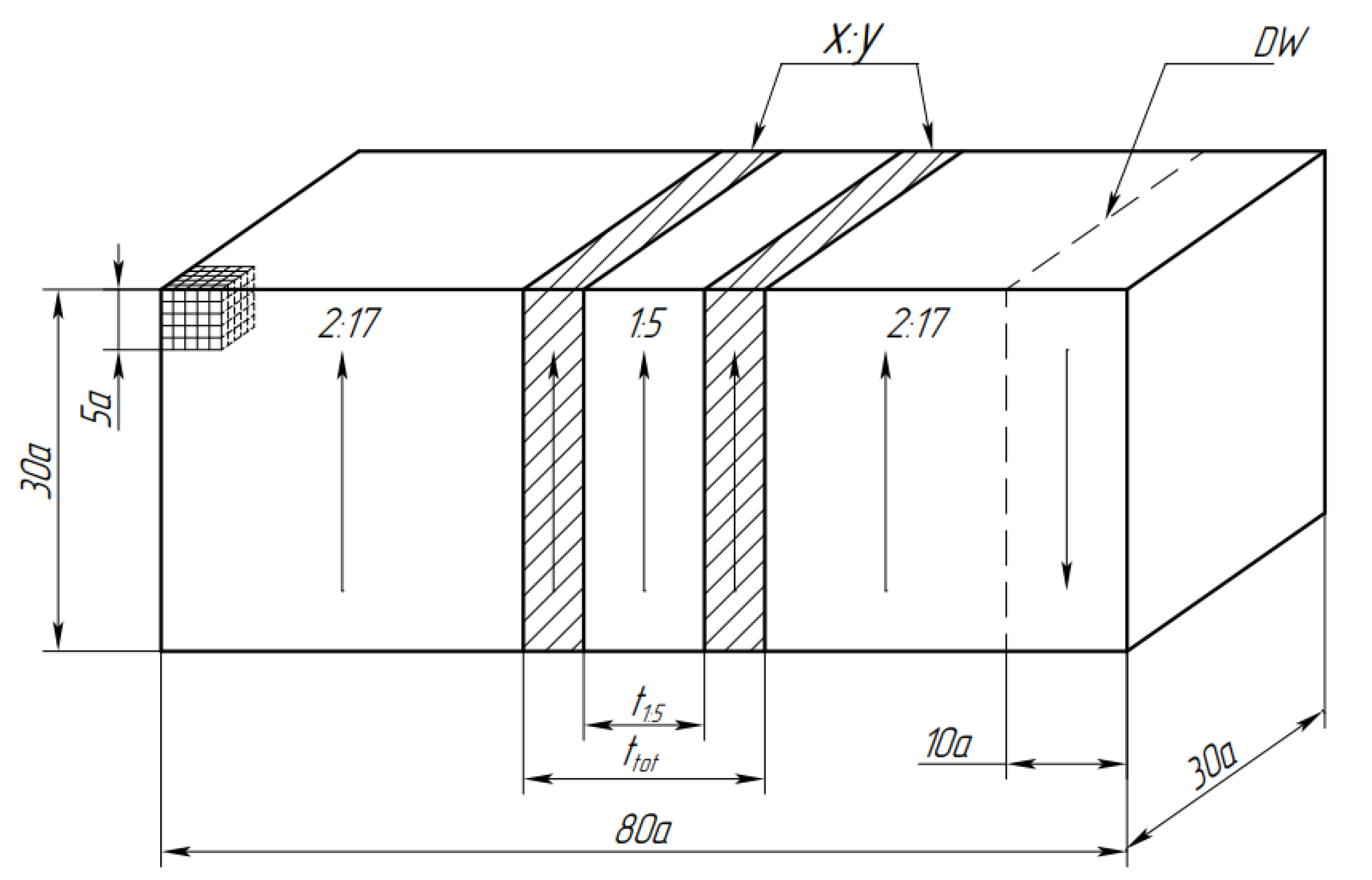
To simulate the influence of the complex composition of the cell boundary to the magnetization reversals of the Sm2Co17-based magnets, finite element micromagnetic simulations were employed. Similar simulations were performed in [2,4,5], however we used two variants of modified sandwich model; these are the 2:17R/2:7R/1:5H/2:7R/2:17R phase layers and 2:17R/5:19R/1:5H/5:19R/2:17R phase layers. To simulate the demagnetization curves of a magnet, the model 80 × 30 × 30 nm in total size was considered. Schematic diagram of the model is given in (Figure 1).
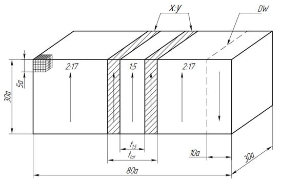
Figure 1.
Schematic diagram of the initial magnetization state of the micromagnetic model containing two 2:17 phase cells and complex (x:y/1:5/x:y) cell boundary, where x:y = 2:7 or 5:19, and showing the existence of magnetic 180° domain wall inside the right 2:17 cell before applying an external magnetic induction (field); DW is the domain wall; t is the width; and a = 1 nm.
The width of the 1:5H phase layer (t1:5) was varied from 0 to 10 nm at a step of 2 nm. The width of the 2:7R phase or the 5:19R phase (t2:7 or t5:19), which is the sum of the right and left parts with respect to the central 1:5R phase with the fixed width, also was increased monotonically from 0 to 10 nm at a step of 2 nm. A 180° magnetic domain wall was introduced into the right 2:17R matrix phase at a distance of 10 nm from the right edge of the model. The initial of the magnetization directions of the left 2:17R phase, 1:5R, 2:7R (or 5:19R) phases, and a portion (to the left of the domain wall) of the right 2:17R phase were set to be upwards, and the initial magnetization direction of the portion of the right matrix phase 2:17R to the right of the domain wall was set to be downward. This domain wall, as was shown in [2,4,5], moves toward the interface of phase boundary in applying an external magnetic induction (field).
The demagnetization curves (μ0M vs. H) were simulated by minimizing the magnetic energy of the system in decreasing magnetic induction. The value of external magnetic induction decreases from 0 to–4 T at a step of 40 mT. The models were discretized by cubic nodes 1 × 1 × 1 nm in size, the linear size of which is less than the domain wall width and the exchange length, similarly to approximations used in [2,4,5].
Calculations of the models at each node were performed by the Landau-Lifshitz-Gilbert equation [8] using software MuMax3, which is a GPU-accelerated software that uses finite-difference discretization for micromagnetic simulations. Since MuMax3 performs best with the power-of-two sizes, even values of component phase widths were used [7,8]. The exchange interaction between different material regions deserve special attention. The exchange stiffness parameter Aex and magnetization saturation Ms are defined in the cell volumes, while requires a value of Aex/Ms properly averaged out between the neighboring cells. For neighboring cells with different material parameters (Aex1, Aex2 and Ms1, Ms2) MuMax3 uses approximation a harmonic mean. We used standard value of a scaling factor (S.F. = 1), which may be used to alter the exchange coupling between regions [8]. The simulation was performed under the same conditions and only the (1:5 and 2:7 or 5:19) phase thicknesses were varied.
Table 1 shows values of the magnetocrystalline anisotropy constant (Ku) and saturation magnetization (Ms) of constituent phases available in [3], which we used for the micromagnetic simulations. Table 1 also shows values of the magnetic saturation (anisotropy) field (μ0∙Hs = 2∙Ku/Ms) of the phases.

Table 1.
Magnetic properties of constituent phases: Saturation magnetization (MS), uniaxial anisotropy constant (Ku), and magnetic saturation field (μ0∙Hs).
2.2. Experimental Methods
The microstructure of as-cast alloys was studied using sections prepared by traditional grinding and polishing procedures and a JXA-iSP100 (JEOL; Tokyo, Japan) scanning electron microscope equipped with an energy-dispersive analyzer. The phase compositions of the alloys were determined by X-ray diffraction (XRD) analysis performed on a Bruker D8 Advance diffractometer (Bruker, Karlsruhe, Germany) using CuKα radiation (λ = 1.54178 Å). X-ray diffraction patterns were processed by the Rietveld method using a Bruker DIFFRAC.EVA™ (Bruker, Karlsruhe, Germany), DIFFRAC.TOPAS™ (Bruker, Karlsruhe, Germany) and ICDD PDF-2 2020 (ICDD, Newtown Square, PA, USA) software. For the quantitative phase analysis, we used Springer Materials Database for the Sm-Zr-Co system as prototypes. We improved only some atomic coordinates (particular positions) for each phase.
3. Results and Discussion
We performed micromagnetic simulations for the two variants of the modified sandwich model using the fundamental magnetic parameters estimated from experimental data in [3]. As the modulus of external induction increases, the magnetic domain wall moves leftwards, and at the first stage of the demagnetization process, was pinned at the 2:7R or 5:19R cell boundary phase. At the second stage of the demagnetization process, the magnetic domain wall was pinned at the boundary between 2:7R (or 5:19R) and 1:5H phases.
The actual position of the domain wall is determined by the ratio between the domain wall energy and magnetostatic energy for each phase [3]. The values of the domain wall energy (γDW = 4∙(Aex∙Ku)1/2, mJ/m2) and width (δDW = π∙(Aex/Ku)1/2, nm) and the exchange length (δex = (Aex/μ0∙Ms)1/2, nm) of the considered phases as well were calculated:
As an example, Figure 2 shows the simulated demagnetization curves of the initial sandwich model (without the 2:7R or 5:19R phase layers; t1:5 = 10 nm) and our modified sandwich model (with the additional 2:7R or 5:19R phase layers; t2:7 or t5:19 = 10 nm, t1:5 = 10 nm) of magnet, in which the first (lesser) and second (greater) plateaus in these curve results from the domain wall pinning at interfaces between 2:7R (or 5:19R) and 2:17R and between 2:17R and 1:5H, respectively.

Figure 2.
Simulated demagnetization curves of the initial sandwich model (a) and modified sandwich model with the 2:7R phase layer (b) of (Sm, Zr)(Co, Cu, Fe)z magnet.
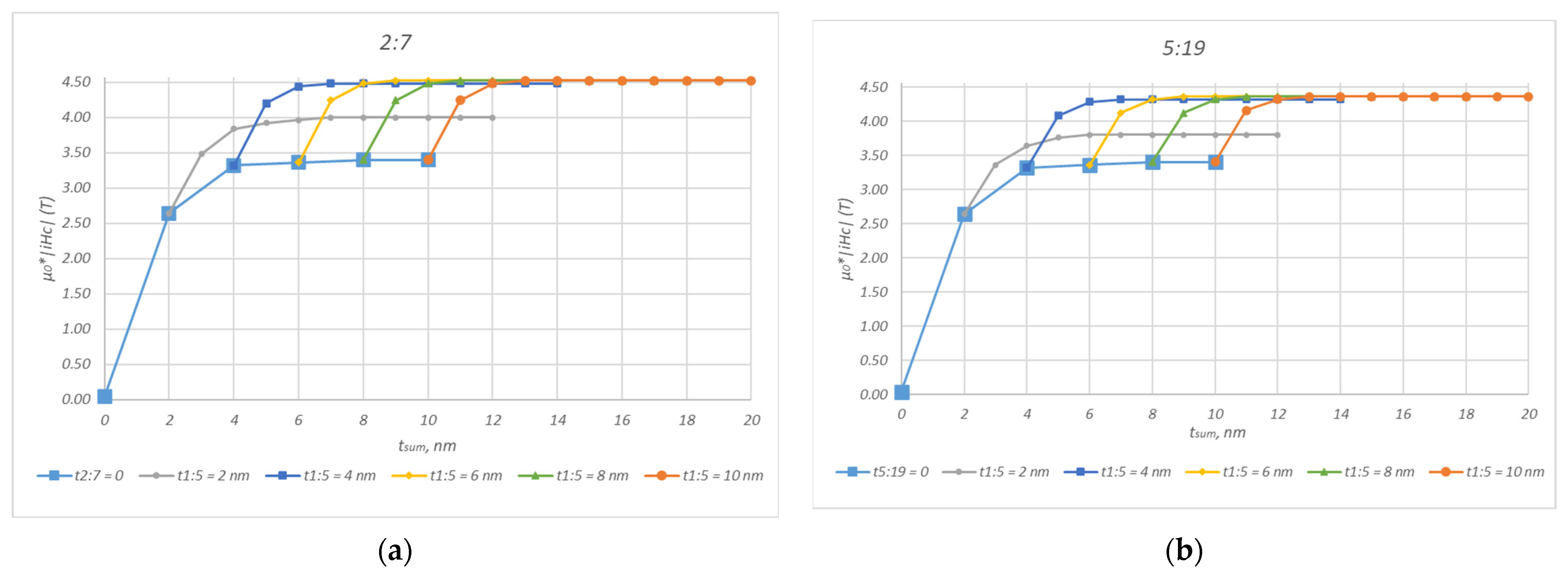
We quantified the effects of the total width (tsum = t1:5+ t2:7 or tsum = t1:5+ t5:19) of the 1:5H and 2:7R (or 5:19R) cell boundary phases on the coercivity (μ0∙IHc) of the model magnet, as shown in Figure 3. An important feature of these curves (μ0∙IHc vs. tsum) is the presence of a plateau at thicknesses of each phase of more than 4–5 nm. On the one hand, this effect can be explained by the fulfillment of the necessary geometric condition associated with the limitations of our model: ti > δDW > δex, where i = 1:5, 2:7, 5:19 and 2:17.
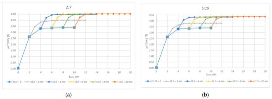
Figure 3.
Calculated coercive force versus total width of cell boundary phase layer for the sandwich model 2:17R/x:yR/1:5H/x:yR/1:5H/2:17R, where x:y = 2:7R (a) and 5:19R (b).
On the other hand, similar types of curves were experimentally observed in [9]. The authors have studied the influence of temperature and annealing time of the maximum coercivity of Sm(Co, Cu, Fe, Zr)7.6 samples and explained the observed dependence by thermally activated diffusion processes occurred during heat treatment of sintered magnets, which make a contribution to the redistribution of chemical elements and changes in the concentration profiles of the main magnetic properties in the ratio of 2:17 and 1:5 phases. We assume that, in addition to the processes of diffusive redistribution of elements between the main phases (2:17R and 1:5H) in these alloys, additional phases (2:7R or 5:19R) can be precipitated along the cell boundary. These phases are additional barriers for domain wall pinning at the cell boundary.
According to the simulation results, the total increase of the coercive force for the modified sandwich model with additional boundary phases (2:7R or 5:19R) relative to the initial magnet model (without additional phases 2:7R (or 5:19R)) was found to be 15–30%.
Obviously, it is difficult to experimentally confirm the described model of increasing coercivity of the Sm-Zr-Co-Cu-Fe alloys, which is reached at the nano-scale level. In our previous studies [10,11,12], we discussed different levels of heterogeneity of the Sm-Zr-Co-Cu-Fe alloys and have related the two-level heterogeneity with the formation of the high-coercivity state of them. The high-coercivity state of the alloys is formed via complex sequential transformations that occurred in the course of heat treatment (solid-solution treatment, quenching, and isothermal and stepped aging) of as-cast alloys. As a result, the periodical phase nano-structure forms and ensures the efficient coercivity mechanism, namely the domain-wall pinning at interfaces. The stable phases typical of the Sm-Co system, the 2:7 and 5:19 phases are among them, participate in the transformations. Below we demonstrate that the 2:7 and 5:19 phases, which, as was noted in [3] can be local phase variants (related to stacking faults) of the 1:5H phase, are identified in the as-cast structure of Sm-Zr-Co-Cu-Fe alloys.
Moreover, in our previous studies [10,11,12], it was shown that, in the case of used Sm1-xZrx(Co0.702Cu0.088Fe0.210)z samples, with x = 0.13–0.19 and z = 6.0–6.8, respectively, which are characterized by high hysteretic parameters and ultimate hysteresis loops that ensure satisfying the condition (BH)MAX ≈ (4πJS)2/4, the 2:7 and 5:19 phases are present in samples quenched after isothermal aging (during isothermal aging, as the intermediate structural constituents in cell-boundary structural constituent, it is assumed the formation of additional phases belonging to the homologous row (Sm, Zr)n-1(Co, Cu, Fe)5n-1–2:7 and 5:19 [14,15,16,17,18]) and even in samples subjected to complete heat treatment for the high-coercivity state. In this case, the high-coercivity samples based on the (Sm, Zr)(Co, Cu, Fe)z alloys are characterized by the presence of phases almost free of zirconium 2:17 [6] and X–Sm(Co0.50-0.63Cu0.22-0.40Fe0.10-0.15)3.5-5.0, which are likely to be the main structural constituents of the high-coercivity cellular structure [10,11,12]. It is noteworthy that our data on the presence of the 2:7 and 5:19 phases in the structure of the (Sm, Zr)(Co, Cu, Fe)z alloys at different heat-treatment stages, in part, coincide with the data of Morita et al. [18,19,20]. In particular, we have showed that the 2:17 and 2:7 phases are the primary-solidification phases that are maximally separated in the material structure and form the main structural constituents. This corresponds to the Liq. + 2:17 + 2:7 region in the phase diagrams of Morita et al. [19,20,21].
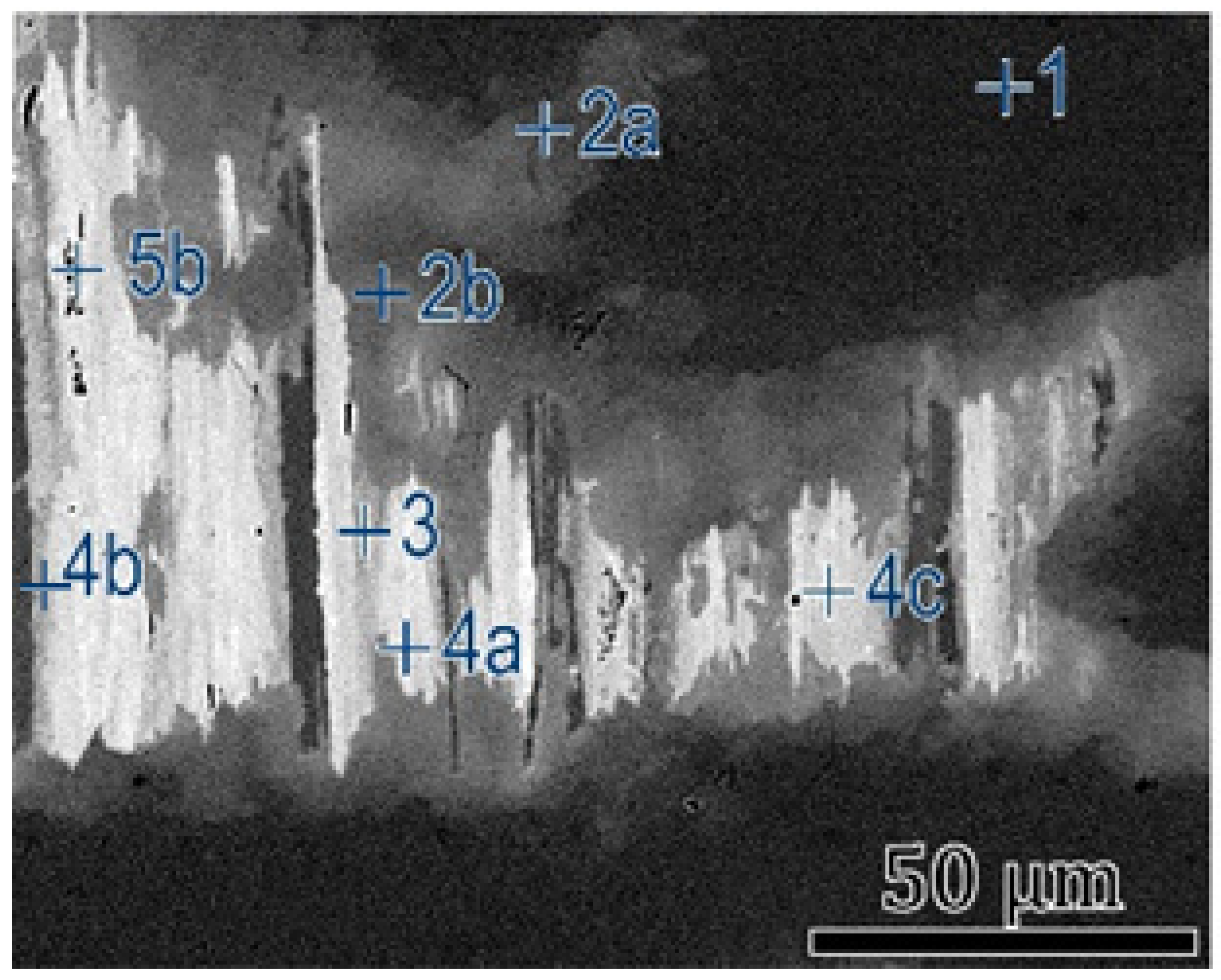
The possibility of the formation of the 2:7 and 5:19 phases, which are found in the vicinity of the 1:5 phase was observed by us experimentally using X-ray diffraction and local electron probe microanalysis. The 2:17R, 1:7H, 1:5H, 5:19R, 2:7R, 2:7H, 1:3R, and 1:3H phases were identified for the as-cast Sm1-xZrx(Co0.702Cu0.088Fe0.210)z experimental alloy with x = 0.13 and z = 6.4. The magnetic hysteretic characteristics of the alloy were studied in [8,9,10], respectively. Figure 4 shows the back scattered electron mode image of the structure of the alloy with x = 0.13, z = 6.4. The composition of the 5:19R phase (point 3) was found to be Sm0.6Zr0.4(Co0.72Cu0.09Fe0.19)3.9 and that of the 2:7R phase (points 4a and 4b) is Sm0.95Zr0.05(Co0.66Cu0.20Fe0.14)3.4 and Sm0.4Zr0.6(Co0.74Cu0.10Fe0.16)3.6, respectively. The composition of the 2:7H phase (point 4c) is Sm(Co0.50Cu0.40Fe0.10)3.7. (Points 1, 2a, 2b, and 5b correspond to 2:17R (Sm(Co0.71Cu0.05Fe0.23Zr0.01)8.3), 1:7H (Sm1-XZrX(Co0.70Cu0.06Fe0.24)5.5-7.0), 1:5H (Sm0.94Zr0.06(Co0.65Cu0.20Fe0.16)4.8), and 1:3H (Sm(Co0.60Cu0.30Fe0.10)2.9) phases, respectively; R and H denote rhombohedral and hexagonal modifications of the phases, respectively).
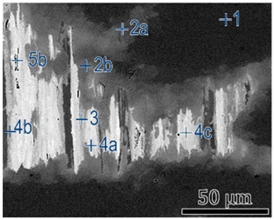
Figure 4.
Microstructure (SEM images, back scattered electron mode) of the as-cast Sm1-xZrx(Co0.702Cu0.088Fe0.210)z alloy sample with x = 0.13 and z = 6.4; EMA points are shown.
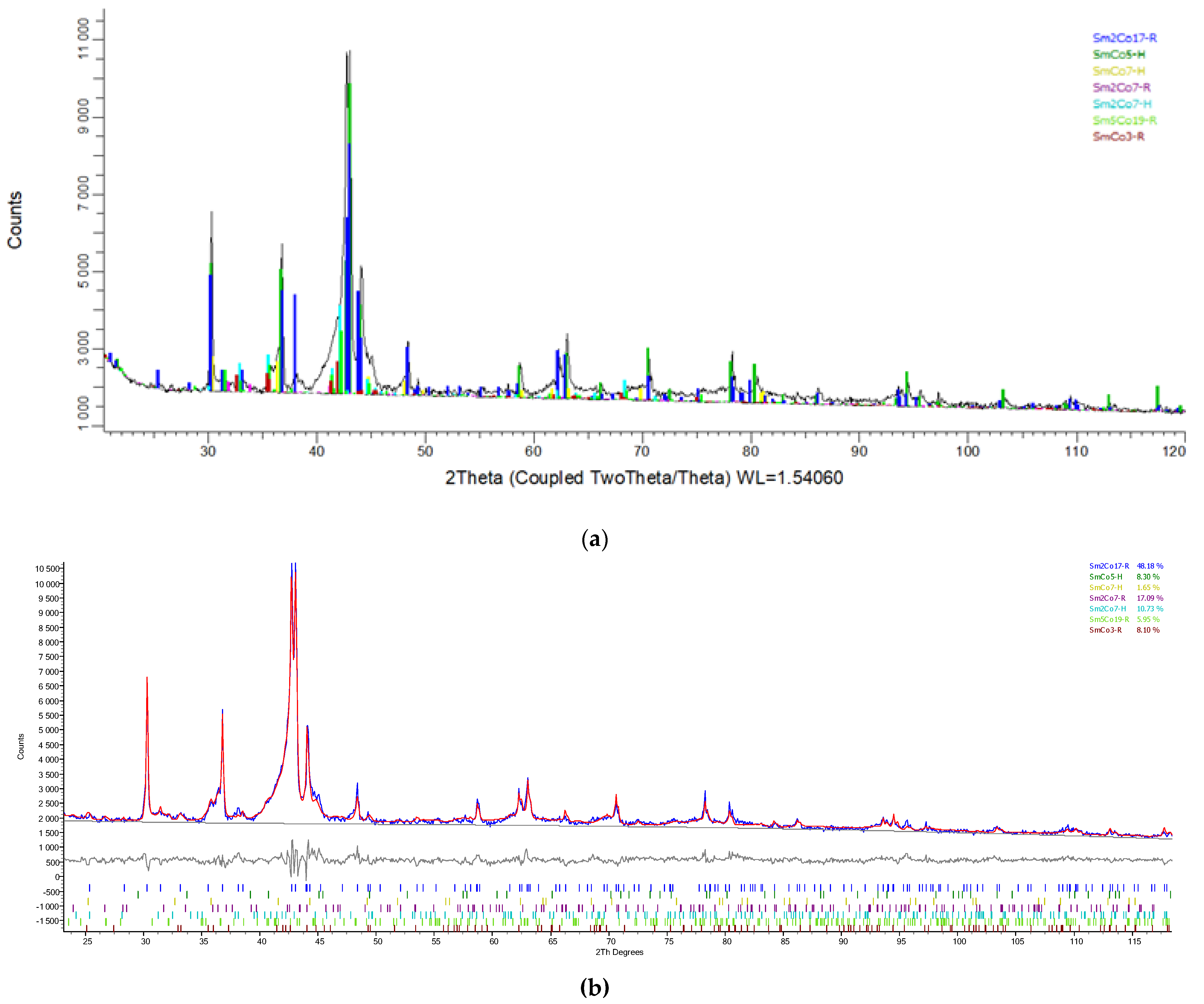
Figure 5a,b demonstrate the X-ray diffraction pattern of the sample, which confirms the identification of the 2:7 and 5:19 phases present in the alloys. The lattice parameters of the phases, their percentage, and parameters of the fine structure (coherent domain size and microstresses) are shown in Table 2.
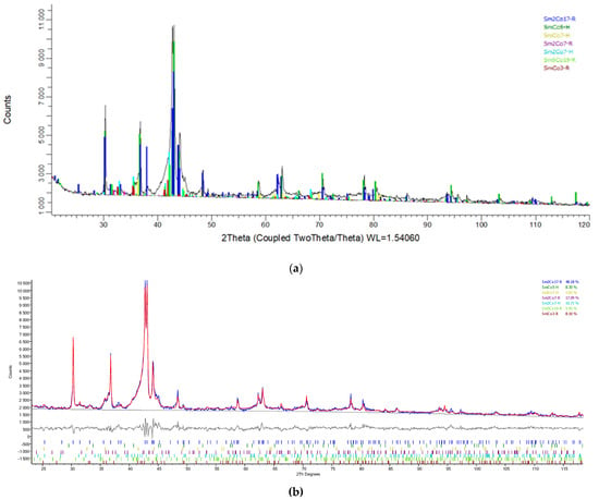
Figure 5.
(a) X-ray diffraction pattern of as-cast Sm1-xZrx(Co0.702Cu0.088Fe0.210)z alloy sample with x = 0.13 and z = 6.4; (b) Rietveld refinement of the pattern.

Table 2.
Crystal lattice and fine structure parameters of the phases identified in the as-cast Sm1-xZrx(Co0.702Cu0.088Fe0.210)z alloy sample with x = 0.13 and z = 6.4.
The data obtained reliably confirm the presence of the above phases in the as-cast quinary alloy that is “natural” combination of them, which is reached by traditional induction melting of Sm-Co-based alloys. The as-cast state is nonequilibrium, is controlled by cooling conditions, and can likely be controllable by heat treatment conditions. This fact makes promising the results of the performed simulation.
4. Conclusions
The micromagnetic simulation was performed using the modified sandwich model of a (Sm, Zr)(Co, Cu, Fe)z magnet, which includes additional domain-wall pinning barriers in the form of 2:7R or 5:19R phase layers. These phases were not considered previously as intermediate layers that result from stacking faults formed in the 1:5 phase. As the width of the cell-boundary barrier increases, the effect of increasing coercivity was found. Moreover, the barrier width being optimum for the increase in the coercive force was determined. The increase in the width of 2:7R or 5:19R phase barriers above the optimum width does not lead to a further increase in the coercive force but can result in a decrease in the magnetization of the simulated (Sm, Zr)(Co, Cu, Fe)z magnet. The possibility of the presence of the phases was demonstrated by an example of the as-cast Sm1-xZrx(Co0.702Cu0.088Fe0.210)z alloy sample with x = 0.1 and z = 6.4, for which the EMA and X-ray diffraction analysis were performed.
The purposeful engineering of the structure of (Sm, Zr)(Co, Cu, Fe)z magnets will likely allow one to improve their hysteretic properties.
Author Contributions
Conceptualization, M.V.Z., A.G.D.; methodology, M.V.Z., V.L.K.; formal analysis, N.B.K., P.A.P.; validation, A.S.A.; data curation, N.A.D.; investigations, M.V.Z., Y.V.M., I.A.S.; writing—original draft preparation, M.V.Z.; writing—review and editing, N.B.K.; visualization, N.A.D., Y.V.M., A.S.B. All authors have read and agreed to the published version of the manuscript.
Funding
This study was carried out within the project “Development of the model of formation of high-coercivity phase and structural states of (R, Zr)(Co, Cu, Fe)z alloys and their synthesis for the production anisotropic bonded powder permanent magnets applied in electric machines.”, projects No. 20-19-00689 funded by the Russian Science Foundation.
Data Availability Statement
The data presented in this study are openly available.
Conflicts of Interest
The authors declare no conflict of interest.
References
- Buschow, K. Intermetallic compounds of rare-earth and 3d transition metals. Rep. Prog. Phys. 1977, 40, 1179. [Google Scholar] [CrossRef]
- Chen, H.; Wang, Y.; Yao, Y.; Qu, J.; Yun, F.; Li, Y.; Ringer, S.P.; Yue, M.; Zheng, R. Attractive-domain-wall-pinning controlled Sm-Co magnets overcome the coercivity-remanence trade-off. Acta Mater. 2019, 164, 169–206. [Google Scholar] [CrossRef]
- Goll, D.; Kronmuller, H.; Stadelmaier, H.H. Micromagnetism and the microstructure of high-temperature permanent magnets. J. Appl. Phys. 2004, 96, 6534–6545. [Google Scholar] [CrossRef]
- Akdogan, O.; Sepehri-Amin, H.; Dempsey, N.M.; Ohkubo, T.; Hono, K.; Gutfleisch, O.; Schrefl, T.; Givord, D. Preparation, characterization, and modeling of ultrahigh coercivity Sm–Co thin films. Adv. Electron. Mater. 2015, 1, 1500009. [Google Scholar] [CrossRef]
- Sepehri-Amin, H.; Thielsch, J.; Fischbacher, J.; Ohkubo, T.; Schrefl, T.; Gutfleisch, O.; Hono, K. Correlation of microchemistry of cell boundary phase and interface structure to the coercivity of Sm(Co0.784Fe0.100Cu0.088Zr0.028)7.19 sintered magnets. Acta Mater. 2017, 126, 1–10. [Google Scholar] [CrossRef]
- Xiong, X.Y.; Ohkubo, T.; Koyama, T.; Ohashi, K.; Tawara, Y.; Hono, K. The microstructure of sintered Sm(Co0.72Fe0.20Cu0.055Zr0.025)7.5 permanent magnet studied by atom probe. Acta Mater. 2004, 52, 737–748. [Google Scholar] [CrossRef]
- Kurichenko, V.L.; Karpenkov DYu Gostishchev, P.A. Micromagnetic modelling of nanorods array-based L10-FeNi/SmCo5 exchange-coupled composites. J. Phys. Condens. Matter. 2020, 32, 405806. [Google Scholar] [CrossRef]
- Vansteenkiste, A.; Leliaert, J.; Dvornik, M.; Helsen, M.; Garcia-Sanchez, F.; Van Waeyenberge, B. The design and verification of MuMax3. AIP Adv. 2014, 4, 107133. [Google Scholar] [CrossRef]
- Durst, K.-D.; Kronmuller, H.; Ervens, W. Investigations of the magnetic properties and demagnetization processes of an extremely high coercive Sm(Co, Cu, Fe, Zr)7.6 permanent magnet. II. The coercivity mechanism. Phys. Stat. Sol. 1988, 108, 705–719. [Google Scholar] [CrossRef]
- Dormidontov, A.G.; Kolchugina, N.B.; Dormidontov, N.A.; Milov, Y.V. Structure of alloys for (Sm,Zr)(Co,Cu,Fe)z permanent magnets: First level of heterogeneity. Materials 2020, 13, 3893. [Google Scholar] [CrossRef]
- Dormidontov, A.G.; Kolchugina, N.B.; Dormidontov, N.A.; Milov, Y.V.; Andreenko, A.S. Structure of alloys for (Sm,Zr)(Co,Cu,Fe)z permanent magnets: II. Composition, magnetization reversal, and magnetic hardening of main structural components. Materials 2020, 13, 5426. [Google Scholar] [CrossRef] [PubMed]
- Dormidontov, A.G.; Kolchugina, N.B.; Dormidontov, N.A.; Zheleznyi, M.V.; Bakulina, A.S.; Prokofev, P.A.; Andreenko, A.S.; Milov, Y.V.; Sysoev, N.N. Structure of alloys for (Sm, Zr)(Co, Cu, Fe)z permanent magnets: III. Matrix and phases of the high-coercivity state. Materials 2021, 14, 7762. [Google Scholar] [CrossRef] [PubMed]
- Soboleva, A.N.; Golovnia, O.A.; Popov, A.G. Embedded atom potential for Sm–Co compounds obtained by force-matching. JMMM J. Magn. Magn. Mater. 2019, 490, 165468. [Google Scholar] [CrossRef]
- Kronmuller, H.; Goll, D. Micromagnetic analysis of pinning-hardened nanostructured, nanocrystalline Sm2Co17 based alloys. Scr. Mater. 2022, 47, 545–550. [Google Scholar] [CrossRef]
- Stadelmaier, H.H.; Goll, D.; Kronmuller, H. Permanent magnet alloys based on Sm2Co17; phase evolution in the quinary system Sm–Zr–Fe–Co–Cu. Int. J. Mater. Res. 2005, 96, 17–23. [Google Scholar] [CrossRef]
- Goll, D.; Stadelmaier, H.H.; Kronmuller, H. Samarium–cobalt 2:17 magnets: Analysis of the coercive field of Sm2(CoFeCuZr)17 high-temperature permanent magnets. Scr. Mater. 2010, 63, 243–245. [Google Scholar] [CrossRef]
- Stadelmaier, H.H.; Kronmuller, H.; Goll, D. Samarium–cobalt 2:17 magnets: Identifying Smn+1Co5n-1 phases stabilized by Zr. Scr. Mater. 2010, 63, 843–846. [Google Scholar] [CrossRef]
- Song, K.; Sun, W.; Chen, H.; Yu, N.; Fang, Y.; Zhu, M.; Li, W. Revealing on metallurgical behavior of iron-rich Sm(Co0.65Fe0.26Cu0.07Zr0.02)7.8 sintered magnets. AIP Adv. 2017, 7, 056238. [Google Scholar] [CrossRef]
- Morita, Y.; Umeda, T.; Kimura, Y. Phase transformation at high temperatures and coercivity of Sm-Co-Cu-Fe magnet alloys. J. Jpn. Inst. Met. 1986, 50, 235–241. [Google Scholar] [CrossRef]
- Morita, Y.; Umeda, T.; Kimura, Y. Phase transformation at high temperature and coercivity of Sm(Co,Cu,Fe,Zr)7–9 magnet alloys. IEEE Trans. Magn. 1987, 23, 2702–2704. [Google Scholar] [CrossRef]
- Morita, Y.; Umeda, T.; Kimura, Y. Effects of Zr content on phase transformation and magnetic properties of Sm(Co,Cu,Fe,Zr)7–9 magnet alloys. J. Jpn. Inst. Met. 1988, 52, 243–250. [Google Scholar] [CrossRef] [PubMed]
Disclaimer/Publisher’s Note: The statements, opinions and data contained in all publications are solely those of the individual author(s) and contributor(s) and not of MDPI and/or the editor(s). MDPI and/or the editor(s) disclaim responsibility for any injury to people or property resulting from any ideas, methods, instructions or products referred to in the content. |
© 2023 by the authors. Licensee MDPI, Basel, Switzerland. This article is an open access article distributed under the terms and conditions of the Creative Commons Attribution (CC BY) license (https://creativecommons.org/licenses/by/4.0/).

