Article

A Metamaterial-Based Double-Sided Bowtie Antenna for Intelligent Transport System Communications Operating in Public Safety Band

by
Rayan Hamza Alsisi
*,
Arshad Karimbu Vallappil
and
Hafiz Abdul Wajid
Department of Electrical Engineering, Faculty of Engineering, Islamic University of Madinah, P.O. Box 170, Madinah 41411, Saudi Arabia
*
Author to whom correspondence should be addressed.
Crystals 2023, 13(2), 360; https://doi.org/10.3390/cryst13020360
Submission received: 2 February 2023 / Revised: 16 February 2023 / Accepted: 16 February 2023 / Published: 19 February 2023

Abstract

:
In this paper, a compact design and new structure of bowtie antenna with dual-band characteristics for the 5G and public safety bands in intelligent transport systems (ITS) is presented. The antenna consists of a double-sided bowtie radiating patch with partial ground plane. A triangular complementary split-ring resonator (TCSRR) metamaterial (MTM) structure was etched on the radiating patch, to develop a dual band and a single notch band between 3.85 and 4.65 GHz. The proposed antenna had an overall size of 36 × 36 mm2 and was fabricated using a FR4 substrate with a thickness and dielectric permittivity (εr) of 1.6 mm and 4.3, respectively. CST microwave studio software was used for the design of antenna. The measured frequency results show impedance bandwidths of 3.45–3.85 GHz and 4.65–5.4 GHz, for a voltage standing wave ratio (VSWR) less than 2. The proposed antenna operates at 3.5 GHz and 4.9 GHz, providing bandwidths of 400 MHz and 750 MHz, respectively, which cover the 5G and public safety bands. A prototype was fabricated and measured based upon optimal parameters, and the experimental results showed consistency with the simulation results. The proposed antenna provided a simulated/measured gain of 5.64 dBi/5 dBi and 4 dBi/3.7 dBi at 3.5 GHz and 4.9 GHz, respectively. The enhanced bandwidth and better gain results of the proposed antenna make it an ideal candidate for an ITS operating in the 5G and public safety bands.

1. Introduction

It is well known that human existence has witnessed the rapid development of state-of-the-art technologies and the quantity of information across all walks of life, covering health, education, defense, and security. All these technologies and information can only be ensured with fast and safe migration of humans, which leads to a strategic conception of intelligent transportation systems (ITS). Interestingly, related to the existing version of ITS, various efforts are already being made by academia, and specifically the automotive industry [1,2,3,4,5], covering (a) state-of-the-art wireless communication technologies, allowing vehicular communication based on diversified sensing facilities; (b) reliable information systems, where vehicular communication utilizes live data, which can be used for car navigation, for example guided parking, etc. This vehicular communication is not limited to vehicle-to-vehicle (V2V) signals but also includes vehicle-to-infrastructure (V2I), such as traffic lights and road signs, etc., involving transportation and traffic management systems. We encourage readers to consult [6] for a detailed understanding of all developmental stages of ITS, with their requirements and applications.
Amongst the key components for building an ITS, both the antenna and its operating frequency play a vital role in vehicular communication systems. With careful consideration of both the antenna and operating frequency band, the advanced features related to traffic and transport management systems can be fully realized [2,3,4,5,6].
We now consider the processes associated with the design of an antenna for an ITS. In [7], an alternative in the form of a flexible microstrip antenna operating at a frequency of 5.9 GHz was offered to the automotive industry. This antenna can take a range of shapes and work under many conditions, specifically for omnidirectional and directional radiating patterns. A compact circularly polarized wide-beamwidth patch antenna was presented for blind spot detection, involving capturing signals from both a wide elevation angle and the entire azimuth range [8]. Moreover, this compact (small size) antenna can be mounted on aerodynamic wireless devices [8]. In [9], a novel method was proposed for efficient communication using multiple low-cost antennas with directional far-field functions. It was further shown that antenna placement is independent of the optimum phase slopes and far-field function, ensuring manufacturing tolerances. The proposed scheme was relevant for low-cost sensor nodes with strict power consumption and complexity requirements. Furthermore, a unidirectional symmetrical radiating pattern antenna with wide impedance bandwidth was designed, fabricated, and tested in [10], and found to be a highly suitable candidate for ITS applications. In 2009, enhanced performance and reliable communication related to ITS were also explored in [11], using a circular array antenna, adding another candidate to the pool. In another set of works [12], a microstrip phased array antenna operating at 5.88 GHz was designed and analyzed to detect a blind spot of an ITS. In [13], the propagation channel properties of antennas for enhanced performance were studied by mounting them at different locations in a car. It was concluded that a pair of antennas deployed on the roof and bumper provided more a comprehensive coverage than a single antenna. In [14], circularly polarized (CP) antennas with hemispherical coverage were designed, simulated, and fabricated in the 4.9 GHz public safety bands. A multi-band CP antenna was developed in another set of works [15]. Moreover, in [16], with the help of simulations and measured results, it was shown that wide-band CP antennas are suitable front-end radiating candidates for a ITS. Here, we consider a novel type of compact antenna, consisting of a half-mode cavity (or substrate). This type of antenna is desirable, as it can operate at two frequencies. In [17], impedance bandwidths of 3.51% and 1.40% at 8.8 and 11.2 GHz were achieved, with corresponding peak gain values of 5.04 and 5.01 dBi. In [18], gain values of 3.23 and 4.38 dBi were measured, corresponding to 5.2 and 5.8 GHz, respectively. Moreover, the fabrication of such antennas is cost-effective compared to many other antennas.
Finally, we consider the most recent works [19], where a band of 700 MHz was identified as jointly applicable for ICS and cell phones. The proposed planar antenna for the 700 MHz band showed a remarkable gain in radiation characteristics. Most of the previous antennas had been designed at 5.9 GHz. Initially, the FCC allocated 5.9 GHz for real-time vehicle safety communication. Now the FCC has proposed reallocating the 5.9 GHz band to the 4.9 GHz band for V2X communication [20], because some bands in the range of 5.9 GHz are used for gigabit-fast Wi-Fi channels. In 2002, the U.S. FCC designated the 50 MHz spectrum, i.e., from 4.94 GHz to 4.99 GHz, for public safety purposes. However, achieving reliable and fast connectivity is still a challenge, as a significant chunk of the available bandwidth is utilized by Wi-Fi in the 5.9 GHz band. Consequently, IoV is restricted from full utility, and this motivated considerations of another suitable spectrum band (e.g., 4.9 GHz) for enhancing the functionality of vehicle-to-everything (V2X) technology. Interestingly, this band was not utilized because of global policies, mainly adopted by the U.S.A. However, the future of V2X is dependent on 4.9 GHz, which will allow the following:
  • Fulfilling consumer needs enabled by 5G,
  • Providing next-generation Wi-Fi connectivity
  • Ensuring reliable communication for V2X under IoV.
This paper used a metamaterial (MTM) structure to design a double-sided bowtie antenna for intelligent transport system communications operating in the public safety band. Various applications of public safety and environmental sensing are outlined in [21]. Metamaterials are an innovative class of artificially created materials that have electromagnetic properties that do not occur naturally. The MTM mentioned in this manuscript are printed metamaterials. MTMs can also be fabricated all in metal and all dielectric [22,23]. The article in [22] introduces a low-cost meta-surface spatial filter that can accept all polarizations and is composed of cheap and thin layers of metal sheeting. The spatial filter in [22] is entirely passive and does not include any dielectric substrates in its design. In [23], an MTM absorber was made of pizza-shaped graphite film with a copper plate for the curve surface. Interestingly, these materials are negative regarding their permittivity, permeability, and refractive index. MTMs have a diverse range of applications in magnetic resonance imaging, the biomedical industry, aerospace sensors, and automotive systems [24,25]. Furthermore, MTMs are used to develop antenna–sensor and antenna systems for gain enhancement, reconfiguration of the radiation pattern, beam steering, and transmit array, and will play a vital role in future wireless communication systems [26,27,28,29]. MTM can also be used as frequency-selective surfaces, for band rejection [30].
This paper proposes a dual-band compact double-sided triangular bowtie antenna with a triangular complementary split-ring resonator (TCSRR) MTM structure. The antenna was designed to operate at 3.5 GHz and 4.9 GHz, and its small size of 36 × 36 mm2 makes it suitable for applications in ITS. The antenna uses an FR4 substrate with a dielectric constant (εr) and thickness (h) of 4.3 and 1.6 mm, respectively. CST microwave studio software was used for the simulation and parametric analysis of the antenna. Good VSWR and radiation pattern characteristics were obtained in the frequency band of interest. Moreover, the parametric analysis of antenna is performed. The final design of the proposed antenna was fabricated and tested, and the results were comparable to the CST simulation. Additionally, its novelty in comparison to the previously presented antennas is presented. The results showed that the proposed antenna is an ideal candidate for sub-6 GHz 5G and public safety band operation.

2. Antenna Design

The dual-band compact double-sided triangular bowtie antenna with triangular complementary split-ring resonator (TCSRR) element fed by a 50 Ω microstrip line is shown in Figure 1, which was printed on an FR4 substrate with a thickness of 1.6 mm, permittivity of 4.3, and loss tangent of 0.018. The primary antenna structure consists of a radiating bowtie-shaped patch printed on the top and bottom layer with a partial ground plane, a 50 Ω microstrip modified feedline, and a triangular-shaped split ring resonator (TSRR) etched from the radiating patch, to provide TCSRR MTM properties for the antenna. The dimensions of the TSRR are shown in Figure 2a. The proposed antenna was connected to a 50 Ω SMA connector for signal transmission. The optimized dimensions of the proposed antenna are listed in Table 1. Finally, based on the optimum design parametric value, the proposed dual-band antenna was fabricated, and the simulation and measured results of the S-parameter and 2D radiation pattern characteristics are shown and described in detail. To study the parameters of the proposed dual-band bowtie antenna, one parameter was changed at a time, while the others were left unchanged. Simulated results were obtained using CST Microwave Studio.
Initially, the triangular split ring resonator (TSRR) CST simulation model shown in Figure 2b was printed on an FR4 substrate (h = 1.6 mm, εr = 4.3, tan δ = 0.025). The unit-cell was a metallic material printed on an FR4 substrate. The unit-cell design and analysis were carried out using CST-Microwave Studio. For the design in CST, perfect boundary conditions (PBCs) were applied to the unit-cell, which consisted of only one TSRR and had two sides that were perfect electric conductors (PECs) along the y-axis, and two perfect magnetic conductors along the z-axis (PMC). For excitation and radiation purposes, the other two sides of the unit-cell (along the x-axis) were utilized for the wave ports [31].
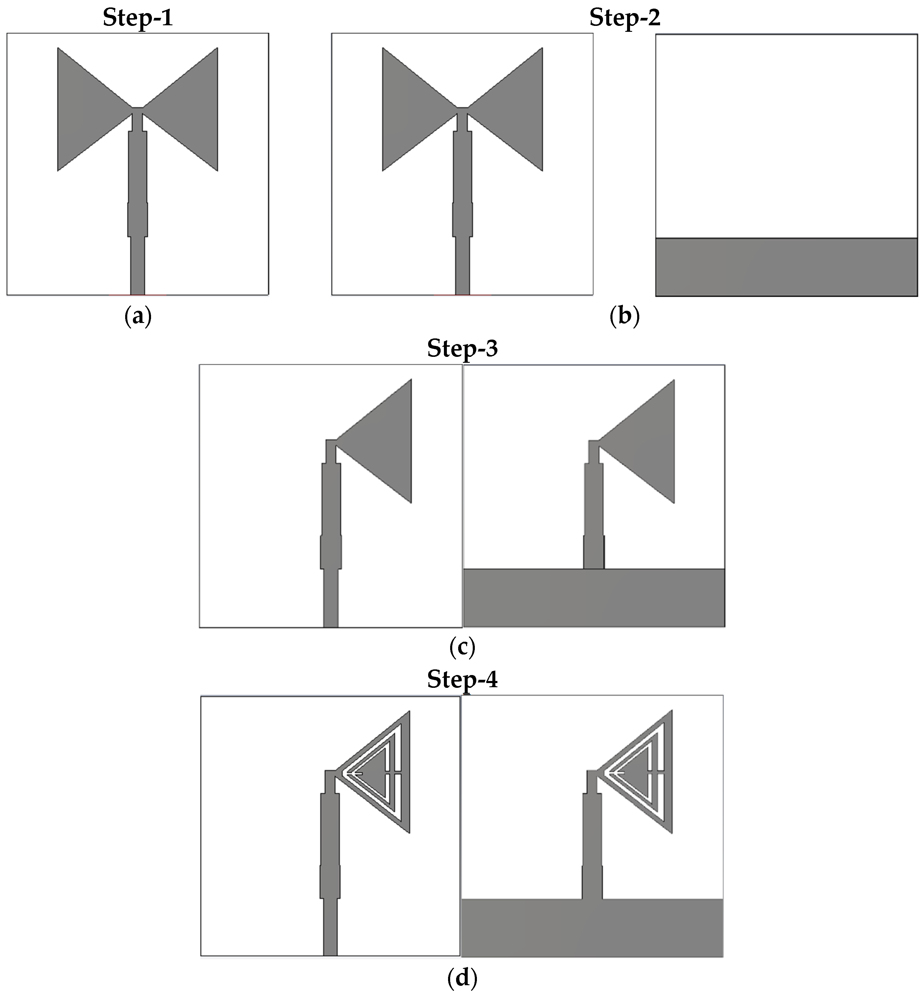
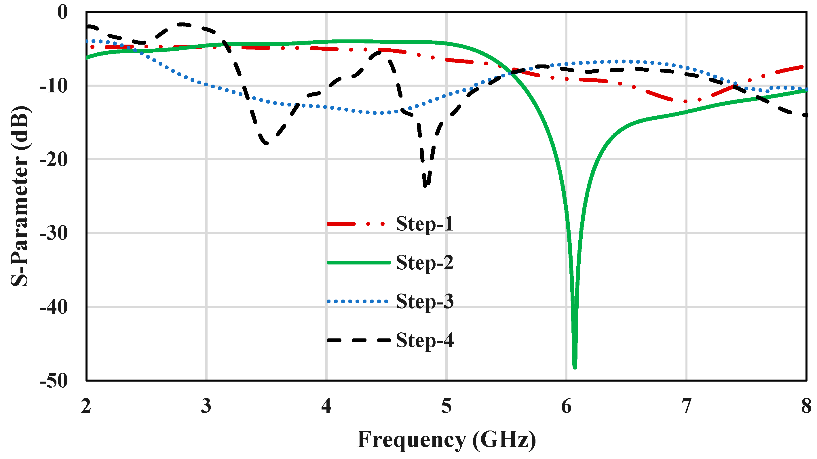
In Figure 3a–d, we present the step-by-step design of the antenna. The antenna design started with a triangular patch bow-tie structure printed on the top layer, and the bottom layer was the complete ground plane shown in Figure 3a. It is shown in Figure 4 that the antenna resonated between 6.5–7.4 GHz in Step 1 at the center frequency of 7 GHz, and the design was simulated using CST Microwave Studio. In Step 2, the complete ground was modified to a partial ground plane, as shown in Figure 3b. This helped to improve the bandwidth from 900 MHz to 2.4 GHz compared to Step 1. The antenna resonated between 5.6–8 GHz in Step 2. In Step 3, one of the triangular patches was moved to the ground plane, as shown in Figure 3c. This helped to shift the frequency range, and the antenna operated between 2.9 and 5.2 GHz in Step 3. In Step 4, as shown in Figure 3d, a TCSRR structure was etched on the triangular patches. This introduced a notched band between 4 and 4.6 GHz, and the antenna showed dual-band behavior. In Step 4, the final design of the proposed antenna resonated at 3.3–4 GHz and 4.6–5.3 GHz. Therefore, the antenna showed dual-band behavior. The antenna resonating frequency at each step shown in Figure 4. The proposed antenna’s initial resonant frequency operated at 3.5 GHz, while its second frequency operated at 4.9 GHz, covering the sub-6 GHz 5G spectrum and the public safety band. A conventional microstrip patch antenna’s (MPA) overall size is 50 × 40 mm2 [32]. The dimensions of the proposed antenna are 36 × 36 mm2, which shows that the size was reduced by 35.2% compared to a conventional MPA.

Parametric Study of the Antenna Design

A TCSRR composed of two concentric metallic triangular rings with two gaps (‘s’) etched on the sides of the rings is shown in Figure 2. An axial time-varying magnetic field caused the flow of currents in the triangular split rings. The induced currents were turned into displacement currents because of the gaps on the sides of the ring and flowed from one ring to another through the inter-ring holes. The equivalent circuit model of the TCSRR consists of equivalent inductance Ls and capacitance Cs, which model the metallic triangular ring inductive behavior and distributed capacitance between the two triangular rings, respectively. The Ls and Cs changed as a result of changing the t1, t2, and s of the TCSRR, which affected the center frequency and bandwidth of the proposed antenna.
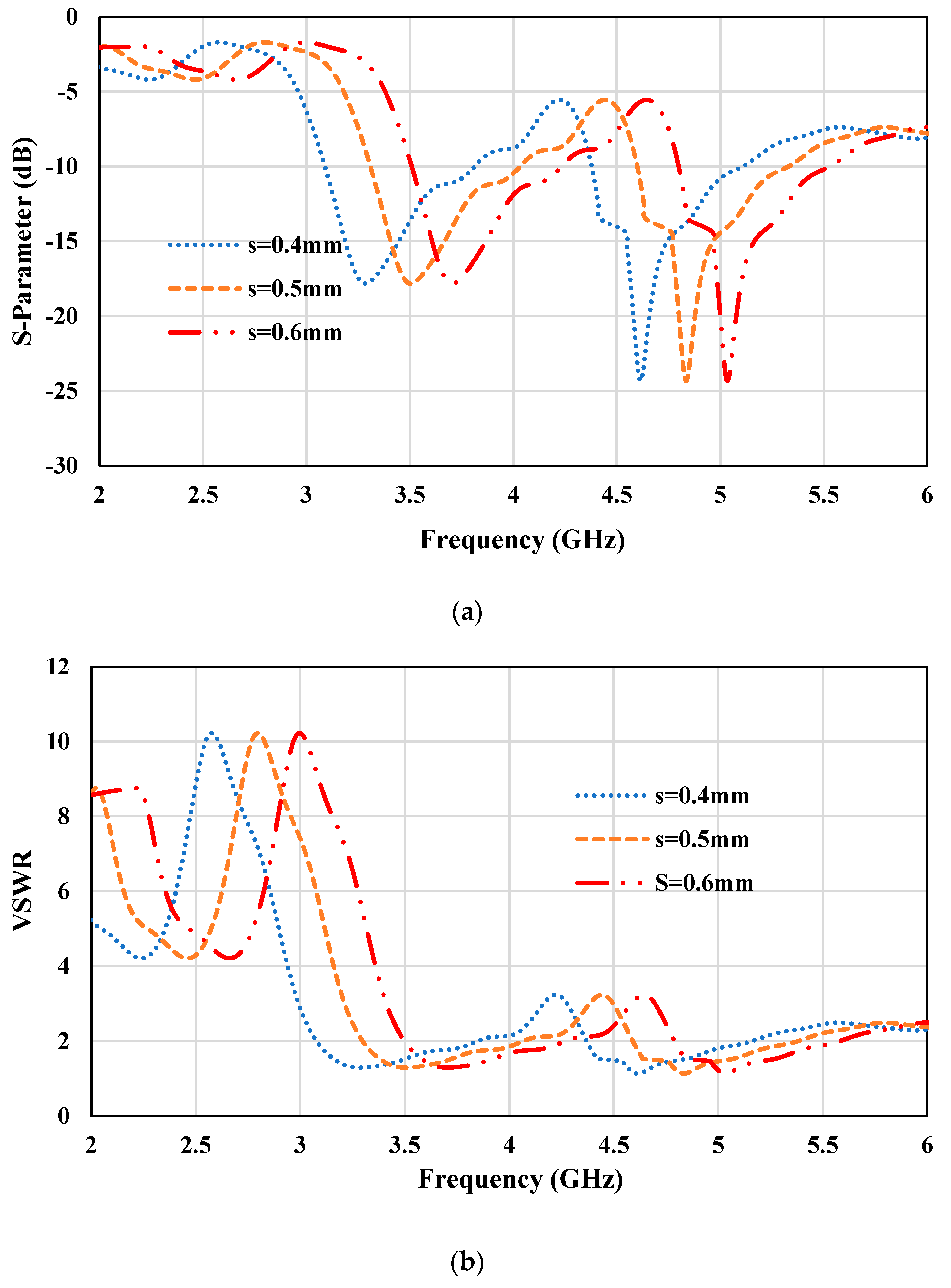
This section discusses the simulation studies that varied the TCSSR slot widths “s” used for the band notch function. The return-loss and VSWR characteristics for s = 0.4, 0.5, and 0.6 mm are shown in Figure 5a,b. The operating frequency and notch band for different values of s are shown in Table 2. Table 2 shows that increasing the slot width s enhanced the notch band range, while reducing s resulted in a drop in the notch band range, but at the same time, caused the antenna’s center frequency to deviate from 3.5 GHz and 4.9 GHz. The 3.5 GHz and 4.9 GHz center frequencies operate in the 5G and the public safety bands, respectively. Reducing the notch band range created interference between the 5G and the public safety bands. Thus, the optimal operating range and rejecting frequency band were achieved at s = 0.5 mm. The antenna operated between 3.3–4 GHz and 4.6–5.3 GHz, and the rejection band was between 4 and 4.6 GHz at s = 0.5 mm. The 600 MHz rejection bandwidth was sufficient to avoid interference between the two operating frequency bands mentioned above.

3. Result and Discussion

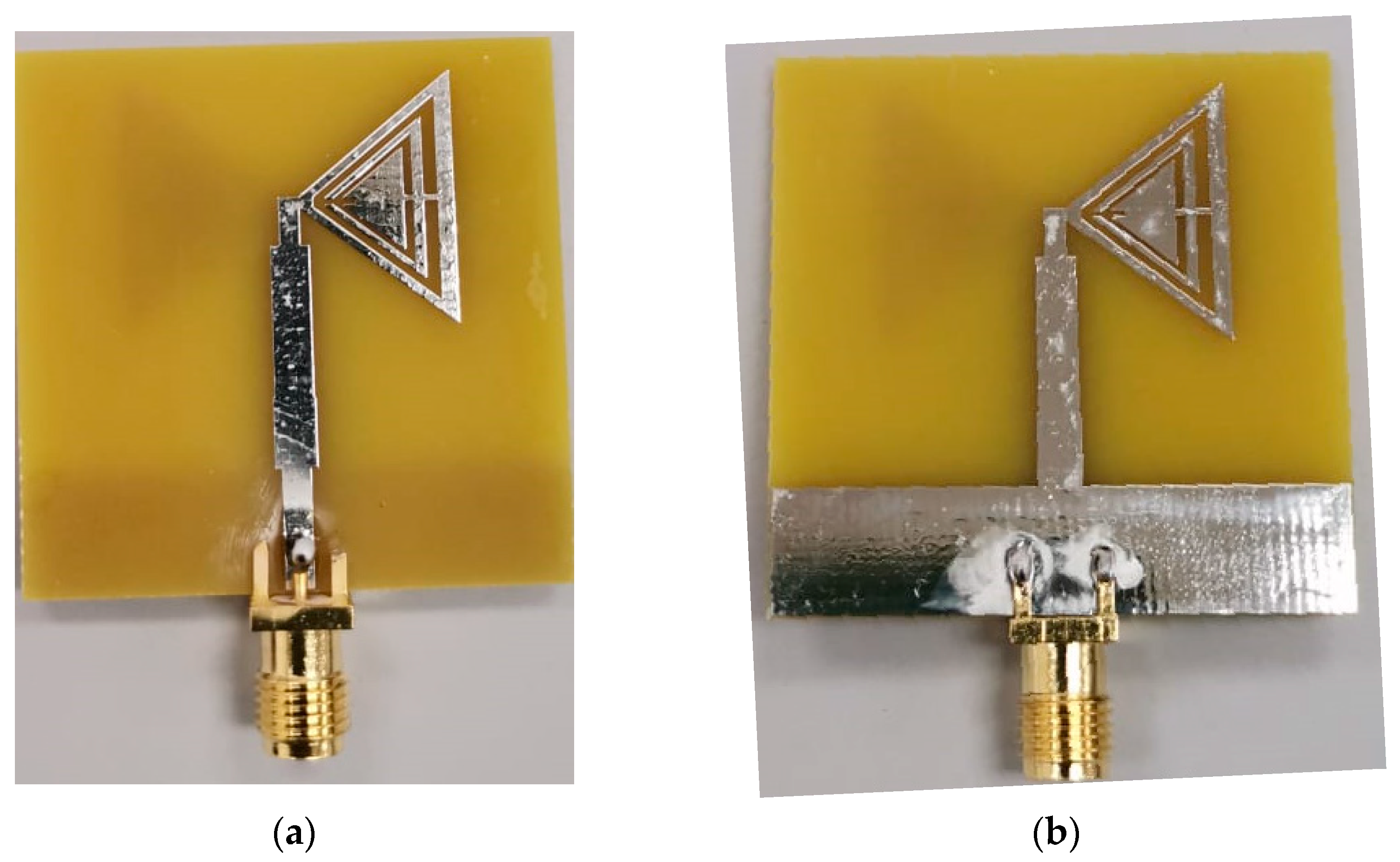
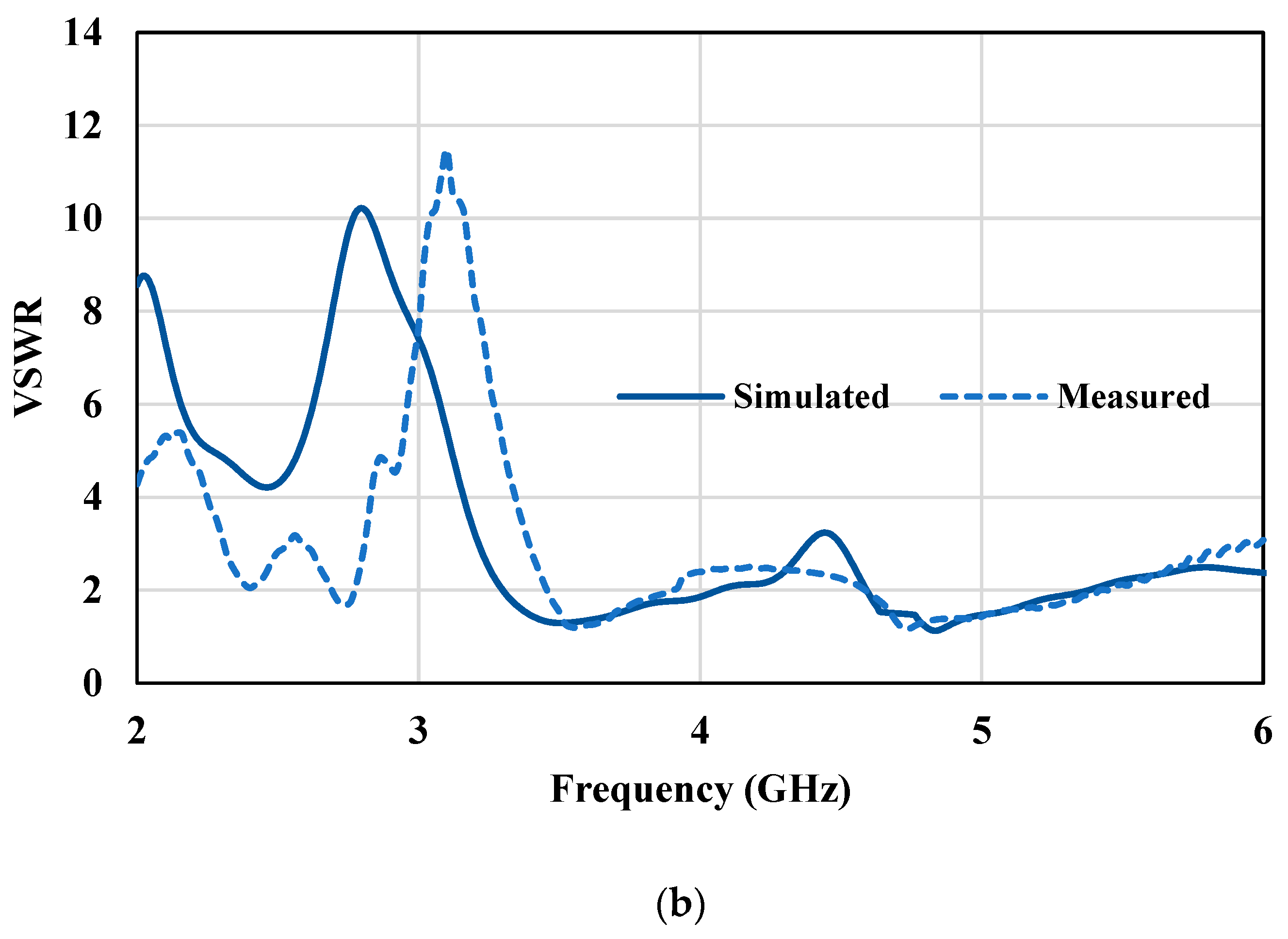
The proposed dual-band antenna based on a bowtie shape was fabricated, and its return loss characteristics were measured and analyzed. The fabricated prototype of the proposed antenna is depicted in Figure 6. The simulated and measured return loss and VSWR characteristics are depicted in Figure 7a,b. The fabricated antenna provided dual-band operation at 3.45–3.85 GHz and 4.65–5.4 GHz, and band-notched between 3.85 and 4.65 GHz. As shown in Figure 7b, the VSWR was below two in the frequency ranges of 3.45–3.85 GHz and 4.65–5.4 GHz. The measured results show that the antenna provided a bandwidth of 400 MHz and 750 MHz in the 5G and public safety bands, respectively. The proposed antenna S-parameters were measured using a Keysight Technologies FieldFox N9916B Vector Network Analyzer.
There was a slight deviation between the simulated and measured return loss results, as shown in Figure 7a,b. This slight discrepancy was primarily due to the fabricated antenna substrate loss tangent and the effect of SMA soldering [33]. This fabrication error could be solved in future by using a high-end low-loss Rogers substrate and precise soldering.
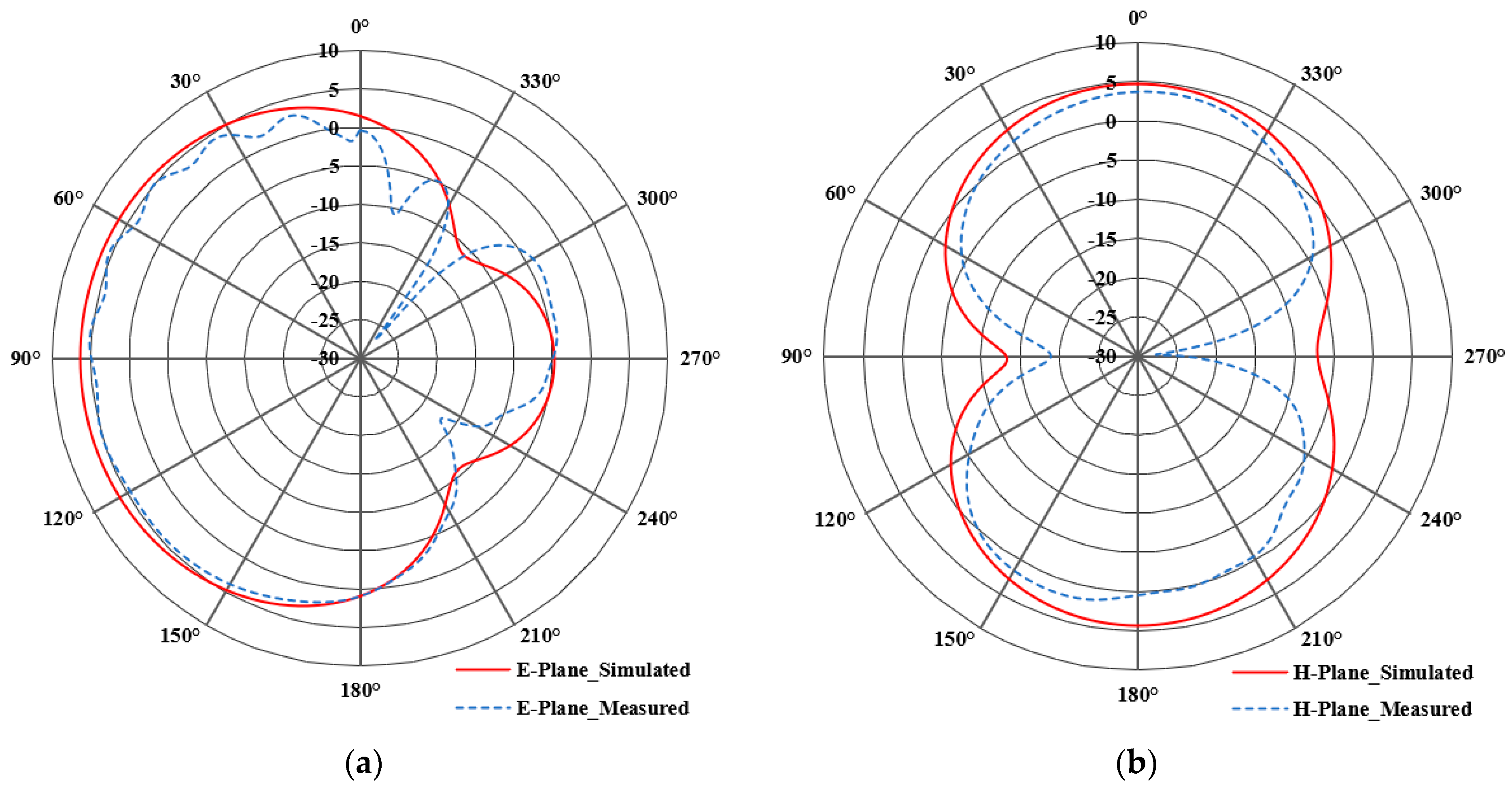
Figure 8 and Figure 9 show the simulated and measured radiation patterns of the E- and H-planes at 3.5 GHz and 4.9 GHz and the radiation pattern measurement setup. The radiation patterns primary objective was to show the antenna’s radiation intensity from a diverse range of angles. The proposed antenna operated similarly to the standard printed monopoles when looking at the radiation patterns in Figure 8 and Figure 9. It can be seen in Figure 8a that the simulated and measured radiation patterns in the E-plane at 3.5 GHz achieved a maximum gain of 5.64 dBi and 5 dBi at 90°. The maximum simulated and measured gain for the H-plane at 3.5 GHz was 4.9 dBi, and 4.2 dBi at 0° can be observed in Figure 8b. Similarly, at 4.9 GHz, the simulated/measured radiation pattern shown in Figure 9a,b has a maximum gain of 4 dBi/3.6 dBi at 30° and 4 dBi/3.7 dBi at 0° for the E- and H-plane, respectively. The radiation pattern at 3.5 and 4.9 GHz looked similar, but with different gains and angles. Figure 9c shows the radiation pattern measurement setup. A microwave source was connected to the transmitting antenna (Horn antenna). The antenna under test (proposed antenna) was mounted on a rotatable positioner and employed as a receiving antenna. Line of sight was maintained between the proposed antenna and the horn antenna. The receiving antenna was connected to a network analyzer (NA) to measure the H-plane pattern. The reading was recorded from the NA after rotating the receiving antenna stand in 10° increments, from 0 to 360 degrees on its axis. The antenna was rotated back to 0° after completing a full 360°. The radiation pattern measurement was repeated in the E-plane rotating both the transmitting and receiving antenna by 90°.
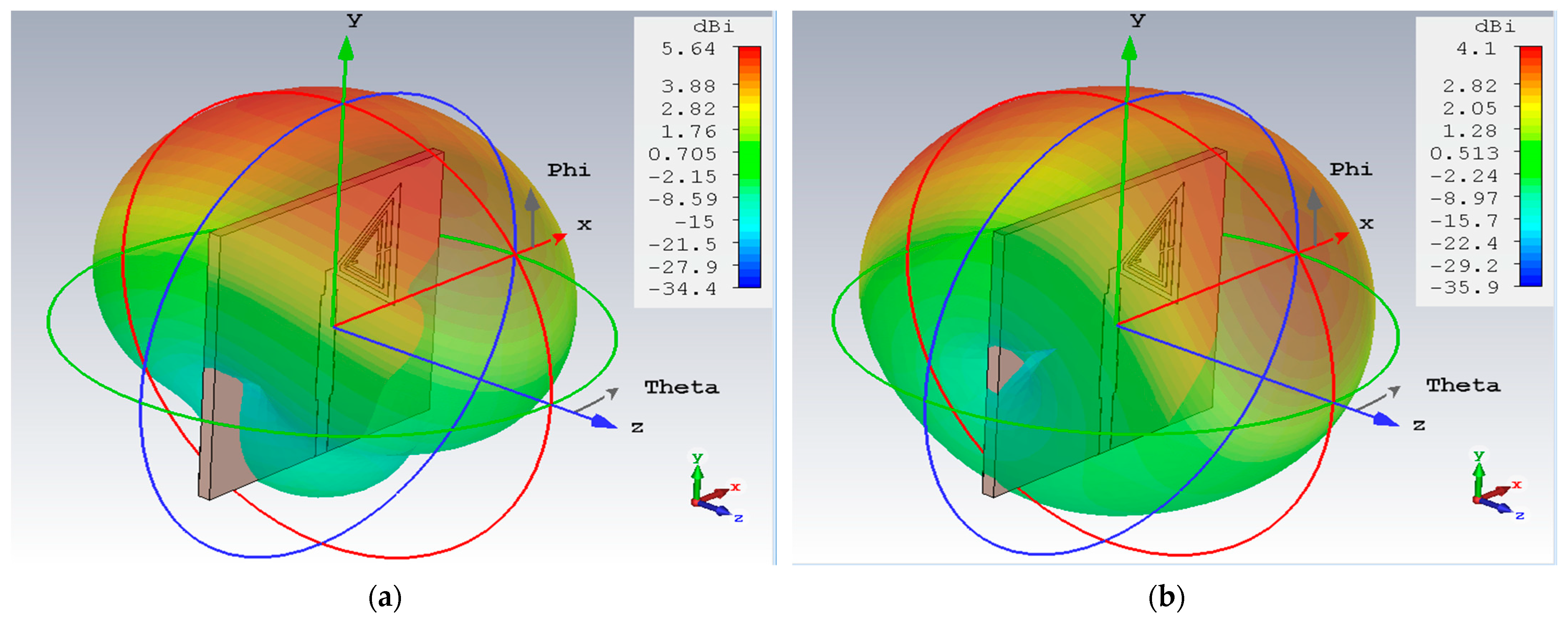
The 3D radiation patterns of the proposed antenna at 3.5 GHz and 4.9 GHz are shown in Figure 10a,b. It can be seen from Figure 10 that the proposed antenna achieved a maximum gain of 5.64 dBi and 4.1 dBi at 3.5 GHz and 4.9 GHz, respectively.
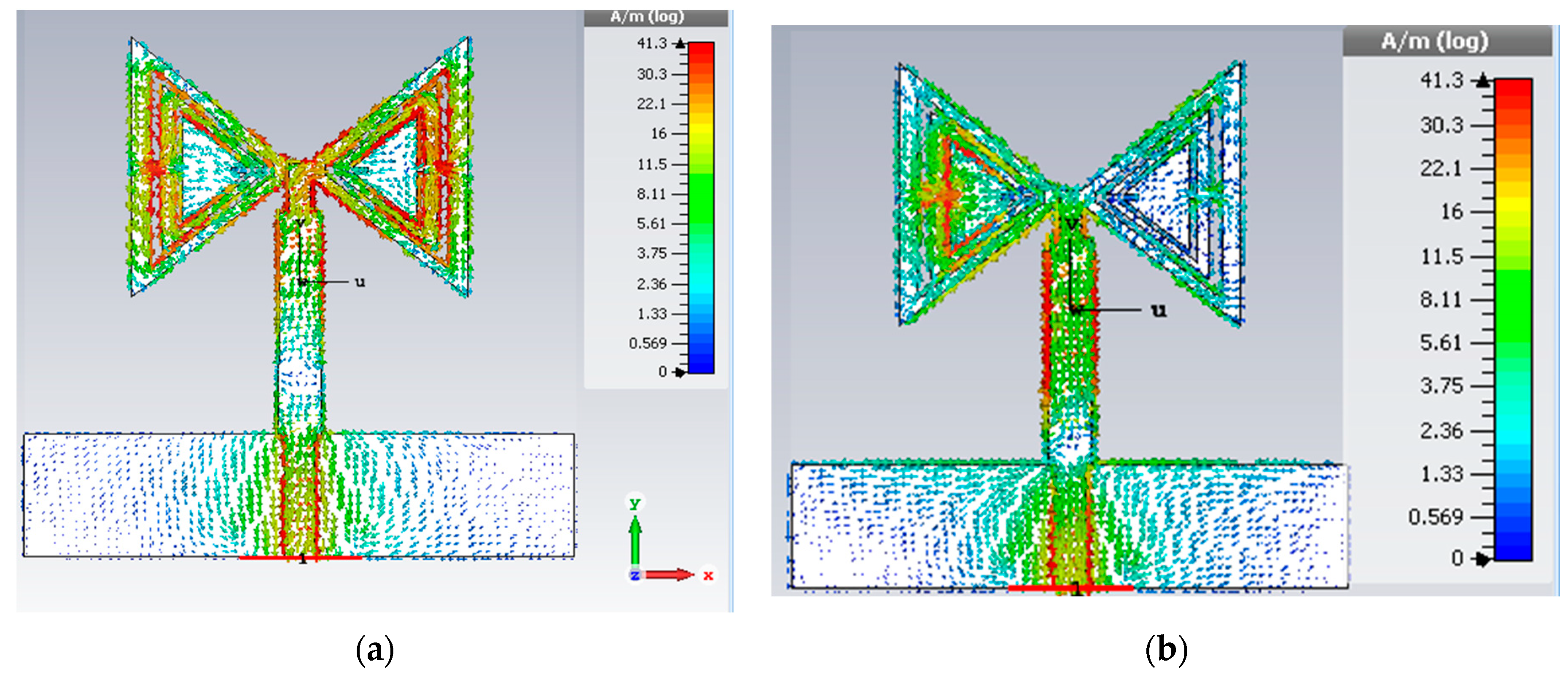
The simulated current distribution for the proposed bowtie antenna at the center frequencies of 3.5 GHz and 4.9 GHz is shown in Figure 11a,b. This helps to understand the reasons for the dual-band behavior of the antenna. Higher and lower current distributions in the antenna are represented by red and blue, respectively, in Figure 11. As can be observed in Figure 11a, at 3.5 GHz, the current was more dominant along the TCSRR of double-sided triangular patches and edges of the modified stepped feedline. The current flows were oppositely directed along the TCSSR edges. According to Figure 11b, at the center frequency 4.9 GHz, the current flows were more dominant around the edges of TCSRR etched from the triangular patch in the ground plane and across the feedline.
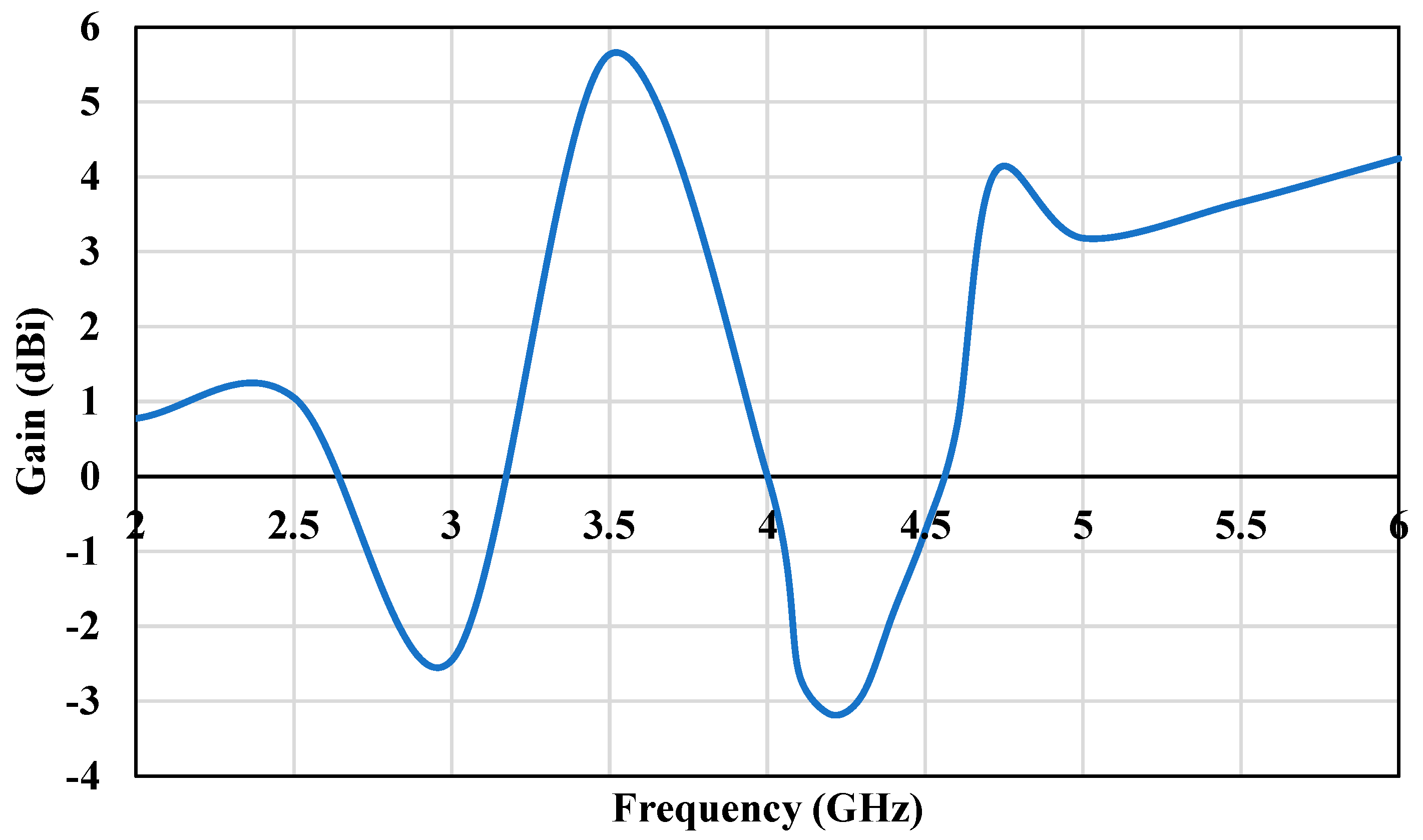
Figure 12 depicts the peak gains of the proposed antenna in the frequency range of 2–6 GHz. The proposed antenna had a gain of 5.64 dBi and 4.1 dBi at 3.5 GHz and 4.9 GHz, respectively. As illustrated in Figure 12, there was a substantial reduction in the maximum gain in the notched frequency region between 4 GHz and 4.6 GHz. The antenna gains at frequencies beyond the notched frequency band ranged from 3 dBi to 5.64 dBi.
Table 3 presents a comparison of the existing antennas that operate at 3.5/4.9 GHz with the proposed antenna. All the previous antennas presented in the comparison table are single-layer designs, consisting of a top layer, bottom layer, and substrate. The top layer is a patch in all cases, but the bottom layer is either a complete ground plane or a partial ground plane/without a ground plane. Table 3 shows that the antenna operating 4.9 GHz and 3.5 GHz achieved a bandwidth and gain of 3.6% and 4 dBi, and 10.5% and 2.42, respectively [34,35]. In [34], the gain improved slightly compared to [35], but the bandwidth of [34] was less than in [35]. Similarly, in [36,37,38], the antenna operated at an 3.5/4.9 GHz improved gain, but the bandwidth was too small. The bowtie antenna proposed in this work improved the bandwidth and gain simultaneously at 3.5 GHz and 4.9 GHz. Therefore, this shows that the proposed antenna is an ideal candidate for the sub-6 GHz 5G and public band spectrum and could be useful for V2X communications.

4. Conclusions

A dual-band double-sided bowtie antenna for ITS was introduced. It was shown that a TCSSR etched on the bowtie radiator patch allow developing a double band and a single notch band between 3.85 and 4.65 GHz. In this design, the proposed antenna functions at 3.45–3.85 GHz and 4.65–5. 4 GHz. This shows that the antenna operates at the sub-6 GHz 5G and public safety bands. Recently, the FCC has allocated the public safety band (4.9 GHz) for ITS communication. The return loss of the antenna was measured and it agreed well with the simulation results. The proposed antenna has the advantages of a low cost, compact size, and ease of fabrication. The experimental results showed that the realized antenna had a very compact size, simple structure, operating frequency, good bandwidth, and high gain, and can be a good candidate for ITS and 5G applications.

Author Contributions

R.H.A. and A.K.V. coined the idea, led, supervised, and evaluated the entire project, edited the write-ups, designed and simulated the proposed antennas. A.K.V., R.H.A., H.A.W. and A.K.V. performed the experimental measurements. A.K.V. completed the initial draft of the paper; A.K.V., R.H.A. and H.A.W. then analyzed, evaluated, and edited the paper. All authors have read and agreed to the published version of the manuscript.

Funding

This research was funded by “The DEANSHIP OF SCIENTIFIC RESEARCH, ISLAMIC UNIVERSITY OF MADINAH, MADINAH, SAUDI ARABIA, Grant Number 650”.

Data Availability Statement

Not applicable.

Acknowledgments

The authors would like to acknowledge the funding from the Deanship of Scientific Research, Islamic University of Madinah, Madinah, Saudi Arabia, under Research Grant No. 650. The authors would also like to thank NUST Research Institute for Microwave and Millimeter Wave Studies, Islamabad, Pakistan, for the support in measurements.

Conflicts of Interest

The authors declare no conflict of interest.

References

  1. Calabuig, D.; Martín-Sacristán, D.; Monserrat, J.F.; Botsov, M.; Gozálvez, D. Distribution of road hazard warning messages to distant vehicles in intelligent transport systems. IEEE Trans. Intell. Transp. Syst. 2017, 19, 1152–1165. [Google Scholar] [CrossRef]
  2. Kannappan, L.; Palaniswamy, S.K.; Wang, L.; Kanagasabai, M.; Kumar, S.; Alsath, M.G.N.; Rao, T.R. Quad-port multiservice diversity antenna for automotive applications. Sensors 2021, 21, 8238. [Google Scholar] [CrossRef] [PubMed]
  3. Syedakbar, S.; Subramaniam, R.; Vijay, R. Orthogonally integrated hybrid antenna for intelligent transportation systems. Appl. Compust. Electromagn. Soc. J. 2021, 36, 519–525. [Google Scholar]
  4. Kishore, N.; Upadhyay, G.; Prakash, A.; Tripathi, V.S. Millimeter wave antenna for Intelligent transportation systems application. J. Microw. Optoelectron. Electromagn. Appl. 2018, 17, 171–178. [Google Scholar] [CrossRef] [Green Version]
  5. Singh, P.; Chaitanya, K.S.R.; Kumari, R. Microstrip patch antenna for application in intelligent transport systems. In Proceedings of the 2019 TEQIP III Sponsored International Conference on Microwave Integrated Circuits, Photonics and Wireless Networks (IMICPW), Tiruchirappalli, India, 22–24 May 2019. [Google Scholar]
  6. Pallavi, M.; Kumar, P.; Ali, T.; Shenoy, S.B. Modeling of a Negative Refractive Index Metamaterial Unit-Cell and Array for Aircraft Surveillance Applications. IEEE Access 2022, 10, 99790–99812. [Google Scholar] [CrossRef]
  7. Zabri, S.N.; Mohd Salleh, N.; Abu, M.; Mohamad, S.Y. Study of a flexible antenna for intelligent transport system application. In Proceedings of the 2017 IEEE Asia Pacific Microwave Conference (APMC), Kuala Lumpur, Malaysia, 13–16 November 2017; pp. 1357–1360. [Google Scholar]
  8. Mondal, T.; Maity, S.; Ghatak, R.; Chaudhuri, S.R.B. Compact circularly polarized wide-beamwidth fern-fractal-shaped microstrip antenna for vehicular communication. IEEE Trans. Veh. Technol. 2018, 67, 5126–5134. [Google Scholar] [CrossRef]
  9. Nagalapur, K.K.; Strom, E.G.; Brannstrom, F.; Carlsson, J.; Karlsson, K. Robust Connectivity With Multiple Directional Antennas for Vehicular Communications. IEEE Trans. Intell. Transp. Syst. 2019, 21, 5305–5315. [Google Scholar] [CrossRef]
  10. Wen, L.; Gao, S.; Luo, Q.; Hu, W.; Yin, Y. Wideband dual circularly polarized antenna for intelligent transport systems. IEEE Trans. Veh. Technol. 2020, 69, 5193–5202. [Google Scholar] [CrossRef]
  11. Yamamoto, K.; Ohno, K.; Itami, M. A study on space division DS/SS Inter-Vehicle Communication system using circular array antenna. In Proceedings of the 2009 9th International Conference on Intelligent Transport Systems Telecommunications, (ITST), Lille, France, 20–22 October 2009; pp. 91–96. [Google Scholar]
  12. Mondal, T.; Ghatak, R.; Chaudhuri, S.B. Design and analysis of a 5.88 GHz microstrip phased array antenna for intelligent transport systems. In Proceedings of the 2010 IEEE Antennas and Propagation Society International Symposium, Toronto, ON, Canada, 11–17 July 2010. [Google Scholar]
  13. Abbas, T.; Karedal, J.; Tufvesson, F. Measurement-Based Analysis: The Effect of Complementary Antennas and Diversity on Vehicle-to-Vehicle Communication. IEEE Antennas Wirel. Propag. Lett. 2013, 12, 309–312. [Google Scholar] [CrossRef] [Green Version]
  14. Maddio, S. A compact circularly polarized antenna for 5.8-GHz intelligent transportation system. IEEE Antennas Wirel. Propag. Lett. 2016, 16, 533–536. [Google Scholar] [CrossRef]
  15. Sharma, N.; Kumar, A.; Arya, A.K. Design of reconfigurable compact dual polarized antenna for multiband operation. In Proceedings of the 2017 International Conference on Computer, Communications and Electronics (Comptelix), Jaipur, India, 1–2 July 2017. [Google Scholar]
  16. Kishore, N.; Prakash, A.; Tripathi, V.S. A multiband microstrip patch antenna with defected ground structure for its applications. Microw. Opt. Technol. Lett. 2016, 58, 2814–2818. [Google Scholar] [CrossRef]
  17. Althuwayb, A.A.; Al-Hasan, M.J.; Kumar, A.; Chaturvedi, D. Design of half-mode substrate integrated cavity inspired dual-band antenna. Int. J. RF Microw. Comput. Aided Eng. 2021, 31, e22520. [Google Scholar] [CrossRef]
  18. Kumar, A.; Chaturvedi, D.; Raghavan, S. Dual-band, dual-fed self-diplexing antenna. In Proceedings of the 2019 13th European Conference on Antennas and Propagation (EuCAP), Krakow, Poland, 31 March–5 April 2019; pp. 1–5. [Google Scholar]
  19. Karasawa, K.; Toda, R.; Yamaguchi, R.; Ashida, K.; Karakama, T.; Kaneko, T. 700MHz band Planar Antenna for Inter-vehicle Communication System and Mobile Phone. In Proceedings of the 2020 IEEE 9th Global Conference on Consumer Electronics (GCCE), Kobe, Japan, 13–16 October 2020; pp. 861–864. [Google Scholar]
  20. Khan, M.; Rizwan, F.; Kim, S. On the Feasibility of 4.9 GHz Public Safety Band as Spectrum Option for Internet of Vehicles. In Proceedings of the 2022 International Conference on Electronics, Information, and Communication (ICEIC), Jeju, Republic of Korea, 6–9 February 2022. [Google Scholar]
  21. Lalbakhsh, A.; Simorangkir, R.B.; Bayat-Makou, N.; Kishk, A.A.; Esselle, K.P. Advancements and artificial intelligence approaches in antennas for environmental sensing. In Artificial Intelligence and Data Science in Environmental Sensing; Elsevier: Amsterdam, The Netherlands, 2022; pp. 19–38. [Google Scholar]
  22. Lalbakhsh, A.; Afzal, M.U.; Esselle, K.P.; Smith, S.L. All-Metal Wideband Frequency-Selective Surface Bandpass Filter for TE and TM Polarizations. IEEE Trans. Antennas Propag. 2022, 70, 2790–2800. [Google Scholar] [CrossRef]
  23. Norouzi, M.; Jarchi, S.; Ghaffari-Miab, M.; Esfandiari, M.; Lalbakhsh, A.; Koziel, S.; Reisenfeld, S.; Moloudian, G. 3D metamaterial ultra-wideband absorber for curved surface. Sci. Rep. 2023, 13, 1043. [Google Scholar] [CrossRef]
  24. Kamal, B.; Ali, U.; Chen, J.; Ullah, S. Applications of Metamaterials and Meta Surfaces; IntechOpen: London, UK, 2022. [Google Scholar]
  25. Kumar, R.; Kumar, M.; Chohan, J.S.; Kumar, S. Overview on metamaterial: History, types and applications. Mater. Today Proc. 2022, 56, 3016–3024. [Google Scholar] [CrossRef]
  26. Esfandiyari, M.; Lalbakhsh, A.; Jarchi, S.; Ghaffari-Miab, M.; Mahtaj, H.N.; Simorangkir, R.B. Tunable terahertz filter/antenna-sensor using graphene-based metamaterials. Mater. Des. 2022, 220, 110855. [Google Scholar] [CrossRef]
  27. Das, P.; Mandal, K.; Lalbakhsh, A. Beam-steering of microstrip antenna using single-layer FSS based phase-shifting surface. Int. J. RF Microw. Comput.-Aided Eng. 2022, 32, e23033. [Google Scholar] [CrossRef]
  28. Lalbakhsh, A.; Afzal, M.U.; Hayat, T.; Esselle, K.P.; Mandal, K. All-metal wideband metasurface for near-field transformation of medium-to-high gain electromagnetic sources. Sci. Rep. 2021, 11, 9421. [Google Scholar] [CrossRef] [PubMed]
  29. Das, P.; Mandal, K.; Lalbakhsh, A. Single-layer polarization-insensitive frequency selective surface for beam reconfigurability of monopole antennas. J. Electromagn. Waves Appl. 2020, 34, 86–102. [Google Scholar] [CrossRef]
  30. Paul, G.S.; Mandal, K.; Lalbakhsh, A. Single-layer ultra-wide stop-band frequency selective surface using interconnected square rings. AEU Int. J. Electron. Commun. 2021, 132, 153630. [Google Scholar] [CrossRef]
  31. Vallappil, A.K.; Khawaja, B.A.; Rahim, M.K.A.; Iqbal, M.N.; Chattha, H.T.; Ali, M.F.M. A compact triple-band UWB inverted triangular antenna with dual-notch band characteristics using SSRR metamaterial structure for use in next-generation wireless systems. Fractal Fract. 2022, 6, 422. [Google Scholar] [CrossRef]
  32. Paragya, D.; Siswono, H. 3.5 GHz Rectangular Patch Microstrip Antenna with Defected Ground Structure for 5G. ELKOMIKA J. Tek. Energi Elektr. Tek. Telekomun. Tek. Elektronika 2020, 8, 31. [Google Scholar] [CrossRef]
  33. Vallappil, A.K.; Rahim, M.K.A.; Khawaja, B.A.; Iqbal, M.N. Compact Metamaterial Based 4 × 4 Butler Matrix with Improved Bandwidth for 5G Applications. IEEE Access 2020, 8, 13573–13583. [Google Scholar] [CrossRef]
  34. Rammoorthyraju, K.; Prasanna Kumar, P. Design of CPW-fed dual-folded slot patch antenna for 4.9 GHz public safety spectrum. In Proceedings of the International Conference on Information Communication and Embedded Systems (ICICES2014), Chennai, India, 27–28 February 2014; pp. 1–5. [Google Scholar]
  35. Vallappil, A.K.; Rahim, M.K.A.; Khawaja, B.A.; Iqbal, M.N.; Murad, N.A.; Gajibo, M.M.; Nur, L.O.; Nugroho, B.S. Complementary split-ring resonator and strip-gap based metamaterial fractal antenna with miniature size and enhanced bandwidth for 5G applications. J. Electromagn. Waves Appl. 2021, 36, 787–803. [Google Scholar] [CrossRef]
  36. Wang, W.; Wu, Y.; Wang, W.; Yang, Y. Isolation Enhancement in Dual-Band Monopole Antenna for 5G Applications. IEEE Trans. Circuits Syst. II Express Briefs 2020, 68, 1867–1871. [Google Scholar] [CrossRef]
  37. Ren, Z.; Zhao, A. Dual-band MIMO antenna with compact self-decoupled antenna pairs for 5G mobile applications. IEEE Access 2019, 7, 82288–82296. [Google Scholar] [CrossRef]
  38. Vinodha, E.; Raghavan, S. Double stub microstrip fed two element Rectangular Dielectric Resonator Antenna for multiband operation. AEU Int. J. Electron. Commun. 2017, 78, 46–53. [Google Scholar] [CrossRef]
  39. Kohli, S.; Dhillon, S.S.; Marwaha, A. Design and optimization of multiband fractal microstrip patch antenna for wireless applications. In Proceedings of the 2013 5th International Conference and Computational Intelligence and Communication Networks, Mathura, India, 27–29 September 2013; pp. 32–36. [Google Scholar]
  40. Kumar, A.; Chaturvedi, D.; Raghavan, S. Low-profile substrate integrated waveguide (SIW) cavity-backed self-triplexed slot antenna. Int. J. RF Microw. Comput. Aided Eng. 2019, 29, e21606. [Google Scholar] [CrossRef]
  41. Ucar, M.H.B.; Erdemli, Y.E. Triple-band microstripline-fed printed wide-slot antenna for WiMAX/WLAN operations. Appl. Comput. Electromagn. Soc. J. 2014, 29, 793–800. [Google Scholar]
  42. Naji, D.K. Miniature Slotted Semi-Circular Dual-Band Antenna for WiMAX and WLAN Applications. J. Electromagn. Eng. Sci. 2020, 20, 115–124. [Google Scholar] [CrossRef]
Figure 1. Geometry of proposed dual-band compact antenna: (a) front view, (b) back view.
Crystals 13 00360 g001
Figure 2. Layout of the triangular split-ring resonator: (a) unit-cell dimension, (b) CST simulation model.
Crystals 13 00360 g002
Figure 3. (a) Primary antenna with the complete ground plane. (b) Antenna with the partial ground plane. (c) Double-sided bowtie antenna with partial ground plane. (d) Double-sided bowtie antenna etched using a TCSRR structure with a partial ground plane.
Crystals 13 00360 g003
Figure 4. Simulated S−Parameter characteristics for the antennas shown in Figure 1.
Crystals 13 00360 g004
Figure 5. Simulated characteristics of the proposed antenna by varying the TCSSR slot width s (a) return−loss (b) VSWR.
Crystals 13 00360 g005
Figure 6. Fabricated antenna prototype: (a) top view, and (b) bottom view.
Crystals 13 00360 g006
Figure 7. Measured results of the proposed antenna: (a) return−loss, (b) VSWR.
Crystals 13 00360 g007aCrystals 13 00360 g007b
Figure 8. Simulated and measured radiation pattern of the proposed antenna at 3.5 GHz: (a) E−Plane, (b) H−Plane.
Crystals 13 00360 g008
Figure 9. Simulated radiation pattern of the proposed antenna at 4.9 GHz: (a) E−Plane, (b) H−Plane, (c) radiation pattern measurement setup.
Crystals 13 00360 g009
Figure 10. Simulated 3D radiation pattern of the proposed antenna at (a) 3.5 GHz and (b) 4.9 GHz.
Crystals 13 00360 g010
Figure 11. Simulated surface current distribution of the proposed antenna at (a) 3.5 GHz and (b) 4.9 GHz.
Crystals 13 00360 g011
Figure 12. Gains of the proposed antenna in the frequency range of 2−6 GHz.
Crystals 13 00360 g012
Table 1. The final dimensions of the proposed antenna.
ParameterDimension (mm)ParameterDimension (mm)
L36Lg6
L16W36
L216.5W18.7
L33.2t10.75
L415t20.6
L511.82s0.5
L69.46
L712
Table 2. Operating frequency and notch bands for different values of s.
s (mm)Operating BandRejection Band
0.43.1–3.8/4.4–5.313.8–4.4
0.53.3–4/4.6–5.34–4.6
0.63.5–4.2/4.8–5.54.2–4.8
Table 3. Comparative study of the proposed antenna with the existing designs.
Ref.Dimension (mm)εrOperating Frequency (GHz)Bandwidth (%)Gain (dBi)Efficiency (%)No. of Layers
[34]0.18λo × 0.24λo × 0.013λo4.34.93.6498Single
[35]0.33λo × 0.34λo × 0.018λo4.33.510.52.42-Single
[36]0.54λo × 0.45λo × 0.017λo3.553.5/4.85.7/42.45/4.56-Single
[37]1.76λo × 0.88λo × 0.009λo 4.33.5/4.95.7/46/870/70Single
[38]0.79λo × 0.79λo × 0.025λo 4.34.76/5.86/9.22/12/18.26.35/5.57/3.982/85/91Single
[39]0.6λo × 0.6λo × 0.041λo 2.24.7/6.5/7.7/8.53.19/2.07/6.75/14.115.45/5.42/7.05/5.64-Single
[40]0.67λo × 0.65λo × 0.04λo2.25.57/7.17/7.65-4.1/3.95/3.5460/50/65Single
[41]0.75 λo × 0.75λo × 0.016λo 2.22.6/3.5/5.536/17/96/6.7/797/95/94Single
[42]0.2λo × 0.21λo × 0.009λo4.43.5/5.88.5/2.51.83/13794/79Single
This work0.4λo × 0.4λo × 0.018λo4.33.5/4.912/165.64/489/73Single
Disclaimer/Publisher’s Note: The statements, opinions and data contained in all publications are solely those of the individual author(s) and contributor(s) and not of MDPI and/or the editor(s). MDPI and/or the editor(s) disclaim responsibility for any injury to people or property resulting from any ideas, methods, instructions or products referred to in the content.