1. Introduction
Spintronic devices have received significant attention in past decades due to their potential to fabricate faster and more energy-efficient circuits than conventional materials. Magnetic nanoparticles (MNPs) and diluted magnetic semiconductors (DMSs) are two important research directions in the field of spintronics. Many achievements have been obtained in the MNPs domain [
1,
2,
3]. For DMSs, since Dietl et al. [
4] revealed the probability of generating room-temperature ferromagnetism (RTFM) in semiconductors by doping transition metal elements, multiple researchers have reported that transition metal-doped semiconductors can hold a Curie temperature (T
C) above RTFM [
5]. In the case of DMSs, the cations are being partially substituted by transition metal atoms, and plenty of experimental data and theoretical models have confirmed that the ferromagnetism in DMSs originates from the doped atoms [
6,
7]. Although DMSs have a great prospect in the field of spin-based technology, there are still obstacles to realizing spintronic applications. One of the main issues in dispute is that the magnetism originating from the metal clusters or secondary phases is not appropriate for practical spin-based devices [
8], because they will affect the uniformity of spin injection. Apart from that, the stability and repeatability of DMSs for spintronic devices are also problems to be overcome [
9]. In order to obtain more suitable spintronic materials, researchers have focused on the non-magnetic elements doped semiconductors. Since the discovery of the unexpected ferromagnetism that was observed in HfO
2 films, the d
0 ferromagnetic materials tend to be recognized as alternative materials for potential spintronics devices [
10]. Moreover, it has been observed that the generating magnetic properties have been generally correlated with defects that can initiate hybridization at the Fermi level and establish long-range ferromagnetism in these systems [
11]. Following this idea, researchers have dedicated a great deal of effort to get ferromagnetism in semiconductors above room temperature by doping non-magnetic ions. Xu et al. [
12] have reported the presence of ferromagnetic properties in Boron-doped ZnO. Experimental and theoretical results have both indicated that the saturation magnetization of boron-doped ZnO increases with the increasing boron component, and the comprehensive analysis suggested that the induced magnetic moments originated from O 2p states. Ye et al., observed RTFM in C-implanted AlN films. The experimental data revealed the Ms value is proportionate to the dose of implanted C+, and the first-principle calculations demonstrated that the ferromagnetism mainly originated from defect complexes involving interstitial C atoms and Al vacancies [
13]. There is also literature [
14] proving that the 2p orbital electrons of the carbon atom are the primary source of the induced magnetic moment in C-implanted TiO
2. Another report [
15] by Hariwal et al., investigated the impact of implanted N ions on the magnetic properties in N-implanted ZnO by varying the implantation angles. The results suggested the concentration of N substituted O defects play a key role in regulating magnetization. However, despite significant achievement gains, discrepancy still persists in these reports and the correlation between the induced ferromagnetism and microstructure still needs to be clarified clearly.
MgO has remarkable properties such as wide band gap, excellent optical properties, and multilevel switching characteristics, which makes it a promising d
0 ferromagnetic material for spintronic devices [
16]. Owing to this, a substantial amount of experimental and theoretical works have been conducted to explore the origin of ferromagnetism in the MgO system [
17]. The synthesis techniques can produce various defects in the materials which invoke changes in their physical and chemical behavior. A consensus has been reached in that the induced ferromagnetism is associated with intrinsic defects or dopant ions in metal oxide semiconductors [
18]. Previous research [
16] has studied the RTFM in Al-doped MgO nanoparticles, and researchers found that the Ms value increased with the increasing oxygen vacancy concentration. Thus, they concluded that the presence of oxygen vacancies can be used as a mechanism to enhance the localized moments
. Conversely, Li et al., demonstrated that the ferromagnetism that was observed in MgO nanoparticles should be attributed to Mg vacancies at the surface [
19]. Besides, Rani et al., reported the annealing temperature dependence ferromagnetism and concluded that the ferromagnetism ordering originated from the composite vacancies [
20]. Based on the above literatures, we speculate that the type of defect is the key factor to understand the induced ferromagnetism.
Ion implantation is a suitable method to introduce defects with controllable modes in materials, which is usually used to induce unexpected physical phenomena that is caused by defects in materials. Implanting nonmagnetic elements has been verified as an effective way to generate ferromagnetism properties in oxides [
14]. Very recently, we have studied the crystalline dependence ferromagnetism in N-implanted MgO [
21] and proved that the extrinsic N ions may play a more important role in magnetic properties than intrinsic vacancies. Singh et al. compared Fe
+ and Zn
+ ion implantation in MgO single crystals and clearly revealed that the induced magnetic behavior resulted from the formation of metal oxides [
22]. Accordingly, the comparative study with different implanted ions in MgO is an intuitive method to further elucidate the role of extrinsic defects. Carbon and phosphorus ion implantation are important technologies in semiconductor manufacturing, and both C- and P-ions are acceptor doping particles for MgO. However, the electron distribution and atomic radius of P and C ions have obvious differences, which will result in discrepancy of lattice damage and defect types in the process of implantation. Previous work has demonstrated that C-implanted MgO can generate ferromagnetism properties [
23], but the investigation of P-implanted MgO has not been systematically reported.
In this paper, the two non-magnetic ions P and C were selected to be implanted into single MgO crystal and their effect was investigated. For the purpose of comparison, X-ray diffraction (XRD), X-ray photoelectron spectroscopy (XPS), absorption spectrum (Abs), and photoluminescence (PL) as practical tools were employed to detect the types and chemical states of the introduced defects in both P-implanted and C-implanted MgO samples. First-principles calculation based on DFT was applied to reveal the possible correlation between the induced ferromagnetism and the defect types and defect configurations.
3. Results and Discussion
To exclude the ferromagnetism contamination, the XPS measurement was carried out. As displayed in
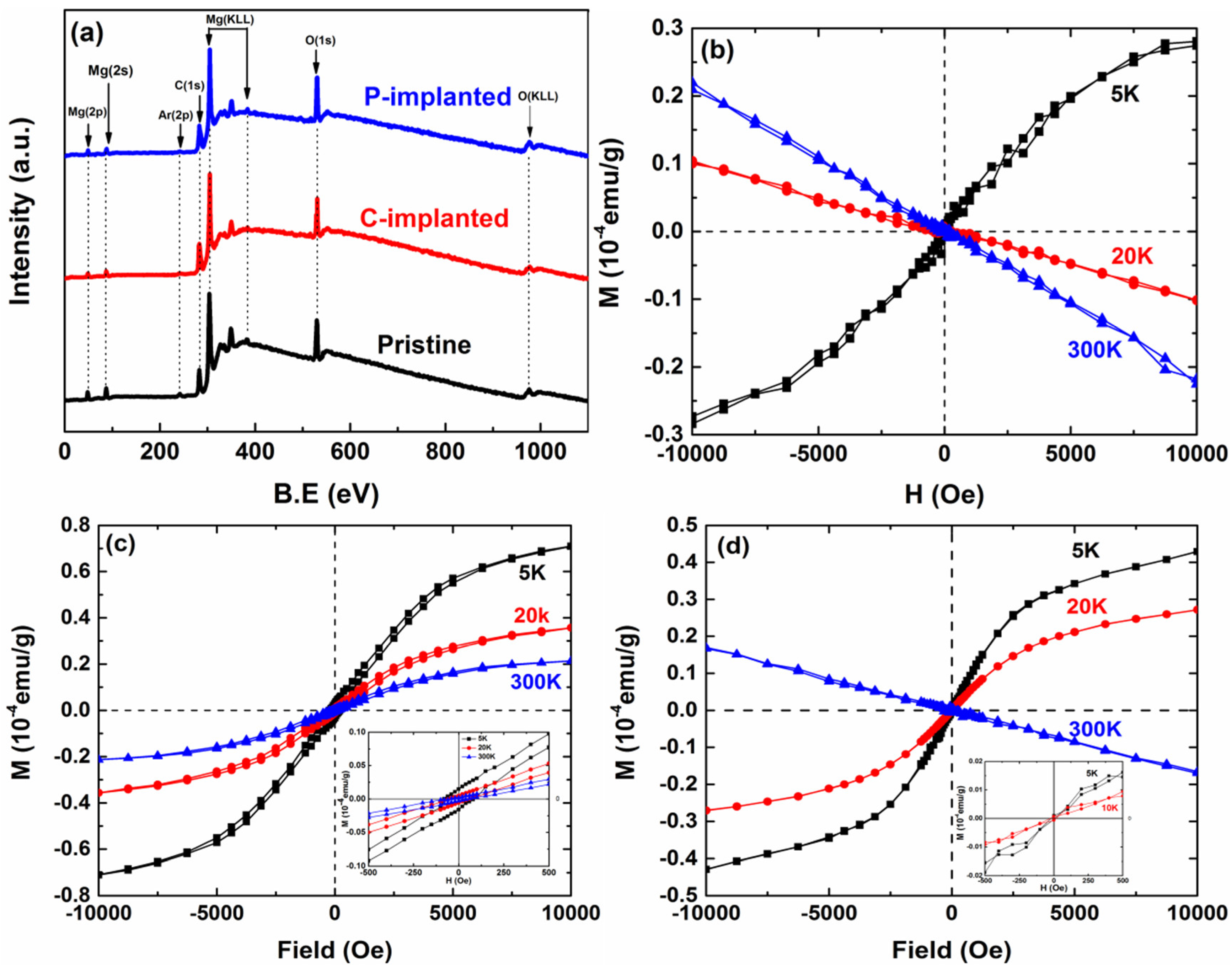
Figure 1a, only the elements Mg, O, C, and Ar were observed in the XPS full spectrum, indicative of the absence of any additional magnetic impurities such as Fe, Co, Ni, etc. The presence of Ar originates from the sample preparation process, and the C is due to the surface contamination.
Figure 1b–d shows the magnetic field-dependent magnetization data (M-H) for the pristine, C-implanted, and P-implanted MgO samples recorded at 5 K, 20 K, and room temperature (RT, 300 K). The pristine MgO displays paramagnetic properties at 5 K, and changes into diamagnetic properties at 20 K and 300 K. However, the measurement results show that the C and P ions that were implanted both changed the magnetic properties of the MgO samples. For C-implanted MgO, the samples display ferromagnetic hysteresis loops at both low and room temperatures. The observed magnetic behavior is consistent with the earlier reports on ferromagnetism in C-implanted MgO [
23]. In the case of P-implanted MgO, the samples display typical paramagnetic properties at 5 K and 20 K, while they show the diamagnetic properties at room temperature. Apparently, the C-implanted MgO samples had a higher Curie temperature than the P-implanted samples. Although the implantation dose for C and P ions is the same, the C-implanted and P-implanted MgO samples still display different magnetic properties. In our previous studies on neutron irradiation of MgO single crystals [
24], the RTFM was not observed. These results indicate that it is almost impossible to introduce stable spin polarization through intrinsic defects in MgO single crystals. Thus, the changed magnetic properties could be attributed to the implanted ions. Usually, several factors could affect the magnetism in the system, including crystallite size, defect types, and their coordination in the lattice structure. A previous report [
25] has theoretically investigated the magnetic properties of N-doped MgO and the authors suggested that the presence of doped N ions in the O position is necessary to generate ferromagnetism in the system. Singh et al. also concluded that the coordination of Mg
2+ was closely associated with the magnetic behavior through ferromagnetic coupling at RTFM [
26]. Therefore, it is essential in this paper to study the defect types and their occupying position of implanted C ions and P ions. The actual result can be made more intuitive by comparing the influence of C ions and P ions on magnetic properties.
High resolution X-ray diffraction (HRXRD) measurements were performed to investigate the effect of C and P ion implantation on the crystal structure.
Figure 2 shows the HRXRD results before and after implantation. Both C-implanted and P-implanted MgO samples presented a highly (200) oriented single crystal structure, and no impurity peak or secondary phase appeared. The pristine MgO samples showed high diffraction intensity and narrow full width at half-maximum (FWHM), indicating that it is an ideal single crystal sample. However, for the C and P ion-implanted samples, there is apparently a reduction in diffraction intensity and obviously broadening in FWHM, suggesting that numerous defects are introduced. In addition, a remarkable phenomenon is that the shift of the (100) peak toward a lower angle in both C-implanted and P-implanted samples, which indicates the lattice constant became larger than that of the pristine sample. For P ion implantation, the substitution of P for Mg, O (P
Mg, P
O), or P in the interstitial position (P
int) will cause lattice expansion. For the case of C ion implantation, only when C replaces O (C
O) [
27] or C is in the interstitial position (C
int), can the lattice be expanded. It is worth noting that the value of the shift angle (0.160°) of the sample after C ion implantation is larger than that (0.139°) of the sample after P ion implantation. This means that the concentration of defects, which can cause lattice expansion in the C-implanted sample, is higher than that in the P-implanted MgO sample.
To further study the element composition and bonding states of the C-implanted and P-implanted samples, XPS measurement for the MgO samples before and after implanting were carried out. For charge referencing, an adventitious C 1s peak located at 284.8 eV was used.
Figure 3a–c shows the XPS spectra of Mg 2p of pristine, C-implanted, and P-implanted MgO samples, respectively. For pristine samples, the Mg 2p spectrum shows a symmetrical peak located at 50.8 eV, which should be assigned to the lattice Mg [
28]. For the implanted samples, it has been observed that both spectra of Mg 2p showed asymmetry in peak intensity, which suggests that Mg defects were produced due to cascading collisions in the process of implantation. As shown in
Figure 3b,c, the Mg 2p spectra can be fitted with two peaks in Mg
L (50.8 eV) and Mg
D (51.7 eV). The Mg
L peak corresponds to the lattice Mg ions, and the Mg
D peak is related to the Mg vacancies [
29]. From
Figure 3b,c, it is shown that the Mg
D relative area of the C-implanted MgO is larger than that of P-implanted MgO, indicating a higher concentration of Mg vacancies in C-implanted samples.
Figure 4a,c shows the spectrum of C 1s of pristine and C-implanted MgO samples. As displayed in
Figure 4a, only a single symmetric peak located at 284.8 eV appeared, which is ascribed to C-C bonding states. For the C-implanted sample, the C 1s spectra can be fitted into three peaks located at 283.8 eV (C
L), 284.8 eV (C-C), and 287.6 eV (C
H), respectively. The peak at 284.8 eV is attributed to C-C bonds (carbon contamination). Pan et al. [
30] have reported that C substitute O (C
O) can shift the C 1s binding energy to a lower value, thus the peak at 283.8 eV (C
L) should be related to the concentration of C
O defects. Moreover, Tan et al. [
31] investigated the XPS spectrum of carbon-doped ZnO. The results indicate that the C substitute Zn can form O-C-O bonds, which have higher binding energy than that of C-C bonds (284.8 eV). According to these results, we concluded the peak at 287.6 eV (C
H) correlated to the C
Mg (C substitute O site) defects. Noticeably, the relative area of C
L is larger than that of C
H, suggesting that the concentration of C
O type is higher than that of C
Mg type.
Figure 4b,d shows the spectra of P 2p in pristine and P-implanted samples. There is no apparent P 2p signal in pristine sample. In
Figure 4d, only a single symmetric peak around 131 eV is observed, which is associated with P-O bonds [
32]. These results reveal that the implanted P ions occupy the Mg sites or the interstitial lattice sites in P-implanted MgO. The previous HRXRD results revealed that the defects which can cause lattice expansion dominate in the C-implanted and P-implanted MgO, which is consistent with the XPS results.
The Abs and PL spectrum are effective tools to detect the existence of specific defects, which were usually considered as the source of the inducing magnetic ordering.
Figure 5a shows the UV-Vis spectrum of pristine and implanted MgO samples. It can be observed that the absorption spectrum of pristine MgO sample presented no absorption peaks. However, the absorption spectra after C-implantation and P-implantation obviously changed and two absorption peaks, located at about 4.96 eV (250 nm) and 2.60 eV (470) nm in both C-implanted and P-implanted samples. The absorption peak located around 4.96 eV is associated with single anion vacancies (F or F
+ center), and the absorption around 2.60 eV can be attributed to the aggregation of F centers [
33]. These results indicate the existence of oxygen vacancy in the implanted MgO samples. Noticeably, the intensity of absorption in the P-implanted sample is higher than that in the C-implanted sample, suggesting that the concentration of oxygen vacancies is higher in the P-implanted MgO sample.
Figure 5b shows the PL spectrum of pristine and implanted samples. The excitation wavelength is 370 nm, thus the excited PL bands should be attributed to structural defects rather than band gap emission. The emission intensity and shape of the excited peaks change apparently after implantation, indicating more defects are introduced in the implanted MgO samples. As displayed in
Figure 5, the emission peaks located at 414 nm, 437 nm, 455 nm, and 469 nm are observed. According to the literature [
34], we attribute the excitation bands at 437 nm and 469 nm to F
2+ center, which is originated from
3B
1u →
1Ag transitions of F
22+ (two F
+ centers nearest to each other). The excitation peak that is observed at 414 nm is owing to
2T
1u →
2A
1g transition F
+ (V
O with one electron) [
35]. In addition, the shoulder peak appeared excited at 455 nm is due to hole trapped at V
Mg [
36]. It is obvious that the emission intensity and integral area of the excited peaks all follow the rule: (C-implanted) > (P-implanted) > (pristine). This means that the concentration of V
O and V
Mg is highest in the C-implanted MgO samples.
4. Frist-Principle Calculations
The Vienna ab-initio Simulation Package was applied on the C-MgO and P-MgO systems to investigate the relationship between the defects and magnetic properties. The Perdew–Burke–Ernzerhof exchange-correlation function was used in the calculation of DOS of states and total energy. A 2 × 2 × 2 supercell with 64 atoms was created to introduce various defects. The schematic structures are shown in
Figure 6. The cut off energy was 400 eV. Each optimized structure in the calculation was relaxed until the Hellman–Feynman force was less than 0.01 eV. The density of states was calculated with a 9 × 9 × 9 mesh. In our calculations, we considered all structures with different single and composite defects that most likely exist in the C and P ion-doped MgO systems. The position of doped ions and vacancies are shown in
Figure 6. The Mg vacancy (V
Mg) and O vacancy (V
O) are inevitably introduced in MgO in the implantation process, and the magnetic moment is induced by V
O and V
Mg is zero and 1.83 μB, which is in good accordance with the previous calculations [
37].
The experimental results reveal the coexistence of various defects. The magnetic moment and total energy of those defects in C-implanted and P-implanted systems are listed in
Table 1 and
Table 2. For the C-implanted MgO system, the single C
O and C
int can give rise to the magnetic moment, while the C
Mg has no distribution to the magnetic moment. Since the ferromagnetic properties originate from the exchange-correlation of various defects, the magnetic behaviors of composite defects are also explored. Since O vacancy cannot generate magnetic moments, we calculated the total and partial spin-polarized DOS (density of states) and PDOS (partial density of states) of the implanted systems containing one Mg vacancy. The configuration of V
Mg + C
O and V
Mg + P
int was considered. The TDOS (total density of states) have been displayed in
Figure 7. The total-DOS and partial-DOS is obviously asymmetrical; this asymmetry is particularly evident around the Fermi level. We can draw conclusions from the DOS distribution that the dopant ions (C and P) can contribute to the magnetism in all defect configurations. In addition, the oxygen atoms that are situated at neighboring sites of the dopant atom can also give rise to the spin polarization. The incorporation of C and P ions in MgO introduce some new states above the valence band, resulting in the shift in the Fermi level in all the doped systems. According to the Heisenberg exchange model, the exchange effect can make the magnetic moments arrange in a certain direction. If the exchange effect makes magnetic moments parallel in arrangement, the system should show ferromagnetism. On the contrary, the system cannot present ferromagnetic characteristics. For the configurations of C
int + V
O, and C
O + V
O, all the calculated magnetic moments are 1.99 μB and 2.00 μB. The induced magnetic moment by V
O is zero, indicating that there is no magnetic coupling in the configurations of C
int + V
O and C
O + V
O. However, the total magnetic moment of C
O + V
Mg is 2.01 μB, which increases slightly in comparison with the single V
Mg (1.83 μB) and C
O (2.00 μB). This means that the spin direction of magnetic moment that is induced by V
Mg and C
O tends to be arranged in parallel. Therefore, we conclude that the ferromagnetic characteristics in C-implanted MgO mainly derive from the configuration of C
O + V
Mg. Meanwhile, the calculations demonstrate the configuration of C
O + V
Mg has the lowest total energy (−365.57 eV) in all the composite defects which can induce magnetic moments. The XRD and XPS experiments have also proven that the C
O and C
int play a dominant role in the C-implanted sample, which agrees well with the magnetic measurement results. In the case of the P-implanted MgO system, as listed in
Table 2, all of the single defect P
int, P
O, and P
Mg can contribute to the magnetic moment with the value 3.00 μB, 0.99 μB, and 0.78 μB, respectively. But the composite defect P
int + V
Mg, P
O + V
Mg, and P
Mg + V
Mg decrease either the magnetic moment value of P
int or V
Mg, suggesting that the exchange interaction favors the unpaired electrons in those configurations with anti-parallel spins.
Based on the experimental and theoretical results, the ferromagnetic and paramagnetic signals should attribute to the presence of C or P ions. The magnetic properties can be explained by the bound magnetic polaron model [
11]. The experimental results revealed that the C-implanted sample has a higher concentration of intrinsic and extrinsic defects in comparison with the P-implanted sample, and the high defect concentration makes the system reach the threshold of magnetic percolation. Meanwhile, the unpaired electrons in the dominant configuration of V
Mg + C
O can be arranged in parallel directions. Thus, the C-implanted MgO sample showed ferromagnetic characteristics. In the case of the P-implanted sample, although the P-related defects can generate magnetic moments, the asymmetrical anti-parallel spin interaction can decrease the value of magnetic moments, and the polarization energy is too small to resist thermal fluctuation at room temperature. For these reasons, the P-implanted MgO system only displays paramagnetism in an external magnetic field.


