Article

PbWO4 Acoustic Properties Measurement by Laser Ultrasonics with the Aim of Optical Damage Recovery

1
Interdipartimental Crystal Research & Analysis Center, Università Politecnica delle Marche, Via Brecce Bianche, 60131 Ancona, Italy
2
Dipartimento di Scienze e Ingegneria della Materia, dell’Ambiente ed Urbanistica, Università Politecnica delle Marche, Via Brecce Bianche, 60131 Ancona, Italy
3
Istituto Nazionale di Fisica Nucleare, Section of Frascati, 00044 Frascati, Italy
4
Dipartimento di Ingegneria Civile Edile e Ambientale, Università Politecnica delle Marche, Via Brecce Bianche, 60131 Ancona, Italy
5
Istituto Nazionale di Fisica Nucleare, a Section of Ferrara, 44122 Ferrara, Italy
6
2nd Physics Institute, Justus-Liebig-University, Ludwigstrasse 23, 35390 Giessen, Germany
7
Dipartimento di Ingegneria Industriale e Scienze Matematiche, Università Politecnica delle Marche, Via Brecce Bianche, 60131 Ancona, Italy
*
Author to whom correspondence should be addressed.
Crystals 2023, 13(4), 556; https://doi.org/10.3390/cryst13040556
Submission received: 27 February 2023 / Revised: 17 March 2023 / Accepted: 20 March 2023 / Published: 23 March 2023

Abstract

:
The paper, at first, discusses theoretical aspects of acoustic wave propagation in lead tungstate (PWO). After that, it introduces the application of laser ultrasonics to PWO crystals with the aim of measuring the acoustic properties and the absorbed energy. A specific set-up has been developed to deposit energy in the crystals by means of shock waves generated by a pulsed Nd-YAG laser. We measured the acoustic properties of the PWO crystals along the crystallographic c ^ axis and measured the acoustic energy absorption. Calculations confirmed that the majority of the energy has been absorbed in the samples. Since in scintillating crystals the radiation damage leads to a decrease in the optical transmission, the paper formulates the hypothesis that the laser energy absorbed can sustain recovery of the optical transmittance properties. Preliminary tests of light transmittance measurements showed a systematic improvement of optical transmittance after laser treatment in a series of PWO samples. These results are consistent and in agreement with the hypothesis, and they support the feasibility of a laser-based method to recover radiation-damaged crystals.

1. Introduction

Lead tungstate, PbWO4, henceforth referred to as PWO, is among the best-known and most efficient scintillators for high-energy physics. The scintillating properties have already been studied [1,2,3,4] as well as the structural and some mechanical properties [5,6], while the optic and elasto-optic behavior has been investigated in [7,8,9,10]. The evaluation of crystals conditions, detecting the defects and internal stress, was examined by means of photoelasticity and other analytical techniques in different papers [11,12,13,14,15,16]. The research on PWO and the development of methods for crystal characterization have a relevant impact on the crystal industry, high-energy physics laboratories, and biomedical imaging. For instance, in high-energy physics laboratories, the calorimeter CMS at CERN is composed of about 80,000 large PWO crystals, and the PANDA project calorimeter too is strongly based on around 16,000 PWO [17,18,19,20,21,22,23,24,25]. This induced a great effort in deepening the knowledge of crystal properties and in the development of quality control methods; in fact, the detection of defects and internal stress was fundamental in the screening of the samples for CMS during the procurement phase. Quality monitoring is still of interest; it is a useful tool for checking crystals exposed to radiation for possible associated radiation damages. For this scope, research is directed towards the development of fast and easy-to-apply recovery techniques, possibly without the need to disassemble crystals from the detectors. In real-world operating conditions, crystals undergo temperature and humidity variations, and they are damaged by ionizing radiation such as X- or γ-rays, hadrons, or heavy ions that can reduce the optical transmittance and, in turn, the light yield of the crystal [26]. At relatively high doses, the radiation damages the crystal structure and creates defects that affect the optical transmittance due to the increased intrinsic absorption of the light produced by the scintillation. Radiation damage can induce, acting also on pre-existing defects, the formation of interstitial vacancies, Frenkel type defects (FTD), and clusters [27,28]. In oxide crystals, the interstitial oxide defects act as electrons or hole traps that absorb the light, creating the color centers. In a self-activated scintillator, such as a PWO, the phenomenon is evident. The color centers are generally metastable, and the sample can be recovered, providing energy, by heating [4,29]. In fact, heating above 200 °C, well below the PWO melting point (1123 °C), depopulates color centers [27,28,29]. Moreover, it must be taken into consideration that, due to radiation damage, its behavior during and after irradiation should be different. This is due to the manifestation of transient radiation defects [30].
As far as we know, the mechanical properties of PWO, such as acoustic properties and energy absorption, have not yet been studied to a full extent from both the theoretical and experimental points of view; hence, in this paper, we first provide the results of a theoretical study of the coupled bulk and lattice wave propagation in a tetragonal crystal. In [31], a detailed analysis of the vibration spectrum (frequency and vibration modes) was provided by modeling the crystal as a continuum endowed with a tensorial microstructure, which represents, at the mesoscopic scale, the crystal lattice. The spectrum depends on a set of 43 macroscopic parameters that can be measured with a series of dedicated experiments. At the present stage, we know only those parameters that characterize the linear elastic behavior by means of the elasticity tensor, i.e., the acoustic properties; the design of the complete set of experiments is a goal to be achieved as a further step in this research.
Moreover, in this paper, we present an original setup and a procedure to subject the crystals to laser shock waves. Once the ultrasonic waves are generated, the experimental layout has been arranged to measure the acoustic properties of the PWO. The evaluated adsorption and transmittance coefficients allow one to measure the deposited energy in the crystals. This dedicated set-up demonstrates, as a first step, the feasibility of a cold recovery of crystal properties by means of energy absorption. PWO samples have been chosen for their wide use in different severe environment, such as CMS and PANDA detectors. Even if the methodology is applicable to a number of crystal and material species, lead tungstate represents one of the most exposed materials to a harsh radiation regime.
A cold recovery method deserves interest because it is more convenient and easier to apply to complex and delicate devices. This paper paves the way in that direction by exploring the possibility of depositing energy in the crystals by means of laser-induced shock waves. In order to progress towards the experimental development of such a method, it is necessary to start with the study of mechanical wave propagation in crystals and the related energy absorption.

2. Materials and Methods

2.1. Bulk and Lattice Waves Propagation in PWO

There are some questions related to the feasibility of the methods that need preliminary answers since, in the vibration process, some of the incoming energy will be lost in the macroscopic vibrations of the massive crystal while another part of the same energy will vibrate the crystal lattice. Crystal recovery is triggered by crystal lattice vibrations, which need to be excited. Therefore, we need to know in advance which frequencies are related to bulk and to lattice vibrations and which amount of energy will be lost, for our purposes, into bulk vibrations. In order to give the mathematical background that is necessary to do this, here we recall some of the results obtained in [30], where the problem was addressed with reference to anisotropic crystals.
Wave propagation in crystals can be modeled either by classical lattice dynamics as in [32] or by the mechanics of continua with affine structure [33]. In this case, the kinematics of a crystal at a point x and time t are described by the classical displacement field vector u = u(x,t), which accounts for the vibrations of the ”bulk” crystal, and by a second-order tensor L = L(x,t) which accounts for the lattice vibrations. Here we briefly recall the results obtained for tetragonal crystals (as PWO) in [31] in the case of a propagation direction m that is parallel to the tetragonal c ^ -axis.
If we seek the solution of the dynamical macro- and microscopic balance laws with linearized constitutive relations in terms of plane progressive waves:
u(x,t) = Lmae,  L(x,t) = Ce,  σ = ξ x·mωt,
where ω is the frequency, m is the direction of propagation, ξ = λ1 > 0 is the wavenumber, and λ is the wavelength, and where the vector a and the tensor C denote respectively the dimensionless displacement and micro-distortion amplitudes, which in the general case are complex-valued. The length Lm > 0 is a macroscopic characteristic length, which accounts for the crystal specimen size. The model introduces two further characteristic lengths, namely the lattice length Ll > 0 and the correlation length Lc > 0 which are related to the non-local effects associated with the gradient of the micro-distortion tensor L(x,t). If we define the two dimensionless parameters
ζ1 = Lc/Lm,  ζ2 = Ll/Lm,
then for ζ1 0 we are considering large samples of crystals, and in the limit ζ1 → ∞ we are zooming into the microstructure. In the case ζ2 0 we are instead neglecting the contribution of micro-inertia with respect to the macroscopic inertia.
It is important to remark that in the limit for ζ1 0 the propagation condition reduces to the classical acoustic propagation condition
A(m)a = c2a,
with A(m) the acoustic tensor associated with the propagation direction m and a the amplitude of the bulk waves; on the other hand, in the ζ1 → ∞ we describe only the spectrum of lattice vibrations. These two limiting cases can be the starting point for the experimental determination of the constitutive parameters.
The propagation condition for (1) is represented by a twelve-dimensional eigenvalues problem whose characteristic equation is
det(A(ξ, ζ1, ζ2) − ω2J) = 0,
where A is a 12 × 12 Hermitian matrix. The eigencouples are accordingly functions of the wavenumber ξ and of the two dimensionless parameters ζ1,2:
ξ → (ωk(ξ), wk(ξ)),  k = 1, 2, …,12
The functional dependences between ω and ξ are called the dispersion relations, and in terms of these relations, we can define the phase velocities vkp and group velocities vkg as:
v k p = ω k ( ξ ) ξ ,    v k g = d ω k ( ξ ) d ξ ,    k = 1 , 2 , , 12
As far as the wave classification is concerned, we may have either:
  • Acoustic waves, whose frequencies ωk(ξ) are going to zero for ξ → 0;
  • Optic waves, for which the limit for ξ → 0 is different from zero: the limit ωk(0) is called the cut-off frequency with group velocities vkg(0) = 0;
  • Standing waves, associated with imaginary values ξ = ±ik, k > 0 for some frequencies, do not propagate but keep oscillating, increasing or decreasing, in a given, limited region within the crystal.
In [30], we found fairly general results that are valid for any anisotropic material and which can be summarized as follows:
  • There ever existed three acoustic and nine optical waves;
  • The cut-off frequencies for the optical waves are the limit as ξ → 0 of the eigenvalues of (3);
  • The frequencies for the acoustic waves are the eigenvalues of (3), which are going to zero in the limit for ξ → 0;
  • The eigenvectors for ξ → 0 are real;
  • There are no standing waves.
These fairly general results were then specialized for tetragonal crystals and propagation directions parallel to the tetragonal c-axis. If we take an orthonormal frame {e1, e2, e3} with e3 directed as the c-axis, we find that the eigenmodes depend on three orthogonal vectors ak, k = 1, 2, 3 which account for the macroscopic “bulk” components of vibrations (as in the classical acoustic wave propagation in three-dimensional linearly elastic and anisotropic materials) and on the following six second-order tensors, which account for the lattice vibrations:
  • Non uniform dilatation:
D 1 = a 0 0 0 b 0 0 0 c
  • Dilatation along e3 and uniform plane strain in the orthogonal plane:
D 2 = a 0 0 0 a 0 0 0 c
  • Shear in the plane orthogonal to e3:
S 1 = 0 α 0 α 0 0 0 0 0
  • Shear between e3 and the direction e = α e1 + β e2:
S 2 = 0 0 β 0 0 α β α 0
  • Rigid rotation around the direction e3:
R 1 = 0 ω 0 ω 0 0 0 0 0
  • Rigid rotation around the direction e = ω1 e1 + ω2 e2:
R 2 = 0 0 ω 2 0 0 ω 1 ω 2 ω 1 0
From the results of [31], we get that, for the tetragonal 4/m class to which PWO crystals belong, we have three acoustic and nine optical waves that depend on 43 independent components of the Hermitian matrix A and completely characterize the dynamical response of the crystal:
(AL) One acoustic wave associated with a macroscopic displacement along c and a combination of the modes D1, S1, and R1, which for ξ = 0 reduces to a macroscopic longitudinal wave;
(AT1,2) Two acoustic waves associated with a macroscopic displacement orthogonal to c, coupled with a combination of the modes S2 and R2. For ξ = 0, these waves reduce to two macroscopic orthogonal transverse waves;
(OL1,2,4,5) Four optic waves associated with a macroscopic displacement along c and with a microdistortion that combines the modes D1, S1, and R1 and which, for ξ = 0, reduces to the pure microdistortions that combine the modes D1, S1, and R1;
(OL3) One optical wave associated with a macroscopic displacement along c and with a combination of the modes D2 and R1;
(OT7,8,10,11) Four optical waves associated with a macroscopic displacement orthogonal to c coupled with a combination of the S2 and R2 modes, which for ξ = 0 reduce to a shear microdistortion and to a rigid rotation.
Further, in [31], the values of the associated frequencies and their dispersion relations were given in an explicit form: accordingly, we may design a set of experiments to evaluate the relevant parameters, as in [8,34], and then it will become possible to “tune-up” the ultrasound source of energy in order to make the crystal vibrate around some selected vibration modes, in order to optimize both the energy dedicated to the recovery and the more effective lattice modes.

2.2. Crystal Samples (PWO)

The lead tungstate, PbWO4 (PWO), is a body-centered tetragonal crystal (point group 4/m with a = b = 0.54619 nm, c = 1.2049 nm (ICDD card n.19–708), density ρ = 8280 kg/m3) [1,5,6]. The three samples studied, which were grown by the Bridgman technique, have a parallelepiped shape and dimensions 31 × 31 × 11 mm. The crystallographic c ^ axis is about normal to the largest surface. The pulsed laser impinges on the larger surface, then the generated shockwave travels along the sample thickness (about 11 mm). In Figure 1a, a typical PWO sample used in this paper is shown. The samples were affected by a lack of transmittance and some general defectiveness, probably due to growth and aging. However, none of the samples had previously been irradiated.

2.3. Laser Ultrasonic Excitation and Measurement Set-Up

A completely non-contact system has been designed in order to excite acoustic waves in a crystal sample and to detect the vibrations generated. This allows to measure its acoustic properties and also to realize an ultrasonic treatment of the crystal.
The ultrasonic shockwave is produced by the interaction of the crystal surface with a high-energy laser pulse; the thermoelastic effect as well as radiation pressure and a continuous interaction of the transmitted optical photons over the internal optical path contribute to the generation and propagation of the ultrasonic perturbation of the crystal structure.
For this purpose, a 1064 nm Nd-YAG pulsed laser (Continuum NY60-10) has been used to generate a series of laser pulses with an 8 ns duration and 10 Hz repetition rate. The energy of each pulse is about E = 200 mJ, carried by a collimated beam having a 6 mm diameter; the beam is not focused in order to reduce the risk of crystal surface damage. The resulting density of energy impinging on the crystal surface is about Ed = 33 mJ/mm2. The beam is shot orthogonal to the crystal surface.
A mechanical positioner allows to move the squared crystal sample in order to direct laser pulses over a cartesian grid of points with a 1 mm step virtually designed on its surface.
Each sample was placed to have the larger surface orthogonally oriented with respect to the pulsed laser beam axis (the c ^ crystallographic axis parallel to the laser beam). The samples were locally excited by laser pulses over a grid of 20 × 20 points with a 1 mm step; the grid was virtually designed on the central area of the crystals surface. Figure 1 schematically represents the crystal geometry and the area on which the laser treatment has been carried out.
The shockwaves generated by the laser pulse are detected and characterized by a laser Doppler vibrometer [35], based on the Mach-Zender interferometric principle, which makes use of a 632.8 nm HeNe laser beam with a bandwidth up to 20 MHz (Polytec OFV 505 laser sensor head with OFV-5000 controller and digital decoder DD-300 for displacement measurement). The laser vibrometer has been set to measure displacement because it has the largest bandwidth; its sensitivity is 50 nm/V. A high-pass filter has been used to avoid the detection of low-frequency fluctuations of the sample surface caused by rigid displacement of the sample. The laser vibrometer signal is acquired by a Tektronix MS02024b digital oscilloscope, which has a bandwidth of up to 200 MHz.
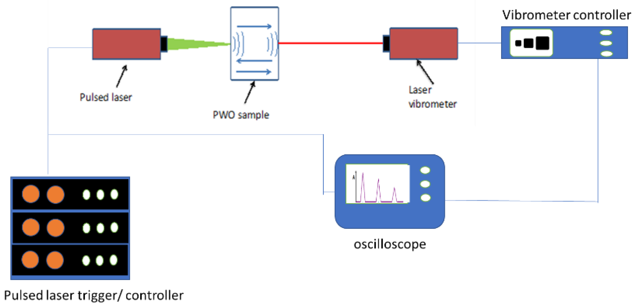
The layout of the set-up is schematically presented in Figure 2, in which the triggering scheme is indicated. Each point of the surface was treated for 1 s (10 laser shots on each point).
When the shockwave is induced in the crystal volume, it runs back and forth, depositing its energy over the probed volume. The speed of sound, impedance, intensity absorption, reflection, and transmittance coefficients (coupled with air) will be evaluated.
Part of the laser energy impinging on the crystal surface is converted into a shock wave at ultrasound frequencies. The shock wave travels across the sample at the speed of sound, hits the opposite surface, and is reflected due to the interface impedance.
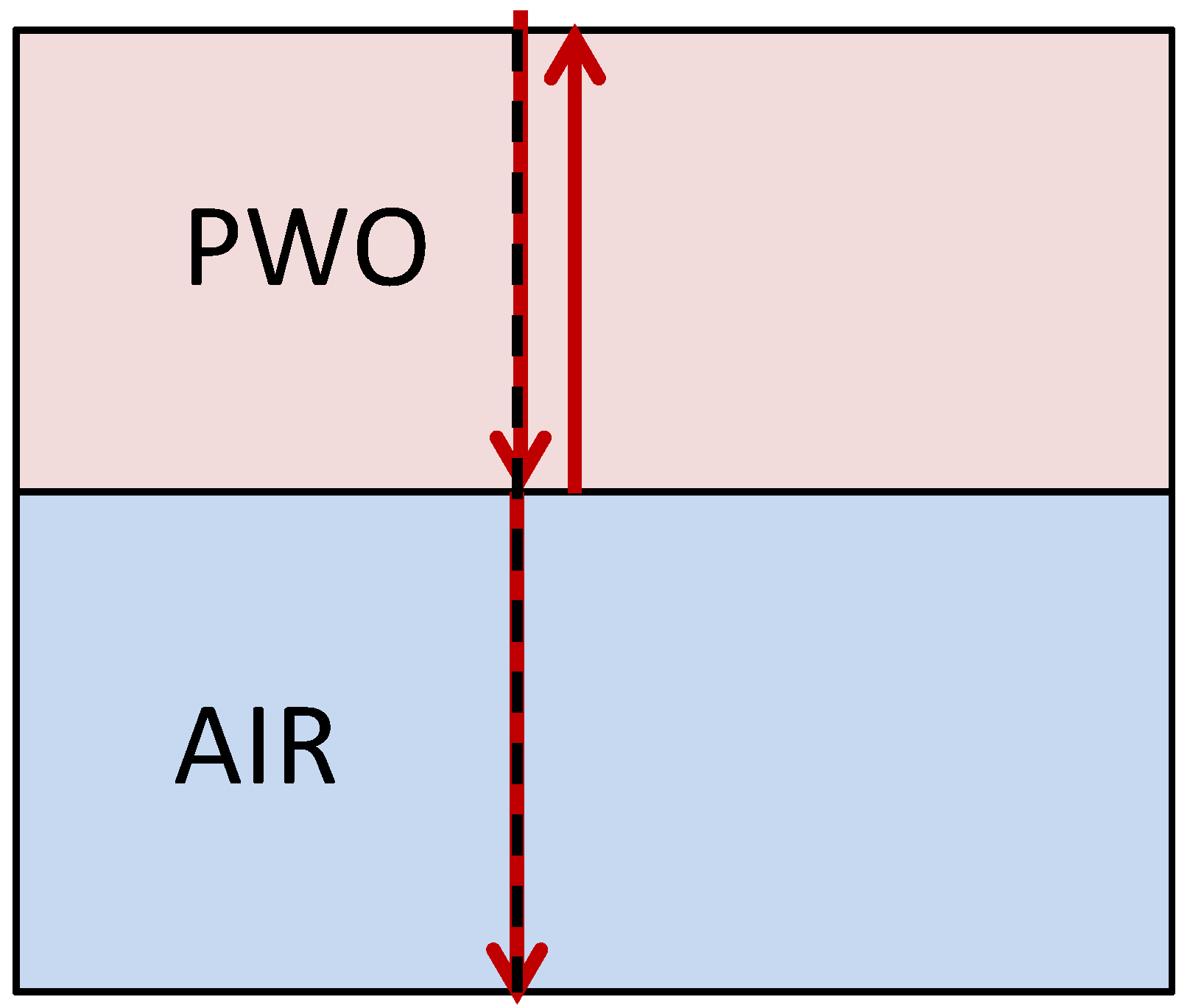
The shock wave at the crystal surface appears as an out-of-plane displacement, which is detected by the laser vibrometer aligned orthogonal to the surface. Due to the high acoustic impedance of the crystal, which is much higher than that of the air, the traveling wave tends to remain in the crystal volume; only a small percentage of the energy is transmitted. Therefore, most of the shock wave energy is deposited in the crystal structure during the subsequent back and forth of the traveling wave, which appears as a series of echoes whose amplitude decays due to absorption.
By measuring the wave echoes with the laser vibrometer, the speed of sound and the wave decay can be measured. Hence, the acoustic impedance (Z), absorption, reflection, and transmission coefficients (coupled with air) are measured without any contact. At the same time, the laser ultrasonic tests, repeated over the sample at several points, deposit some energy onto the crystal, therefore have all the characteristics of the crystal defect recovery method that we aim to study. In Figure 3, a schematic drawing representing the envelope of the series of echoes is shown.

2.4. Data Acquisition and Processing

As already said, our objectives are twofold:
  • Apply the laser ultrasonic method to measure the acoustic properties (speed of sound, acoustic impedance, acoustic reflection coefficient, and acoustic transmission coefficient) of PWO crystals by a fully non-contact method.
  • Assess if the pulsed laser excitation of PWO crystals causes any recovery of the crystal’s optical properties (an increase in optical transmittance).

2.5. Light Transmittance Measurements

We have used an optical spectrophotometer (JASCO V670) to measure the optical transmittance in the wavelength range λ = 300–700 nm with a 2 nm resolution. The integration time was set to 50 nm/min.
The three samples of PWO have been tested before and after the laser pulse treatment; this is done in order to observe if the energy deposited by the pulsed laser treatment has caused any change in transmittance spectrum.

3. Results

3.1. Measurement of Acoustic Properties of PWO

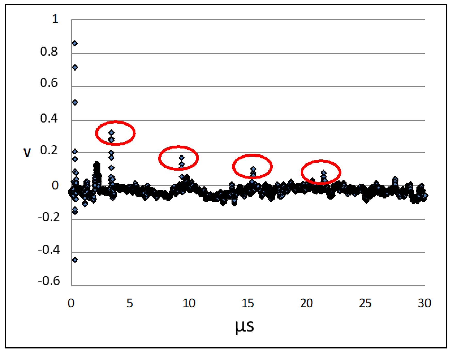
A typical vibration signal obtained when a laser pulse impinges on the crystal surface and excites a shock wave is shown in Figure 4. The series of peaks due to the pulse bouncing back and forth across the crystal are clearly recognizable (red circles). The processing of such a signal allows one to determine the speed of sound C, as in Equation (6), where T is the sample thickness and Δt is the time between two subsequent rebounds.
C = 2 T Δ t
The acoustic impedance Z is defined as
Z = ρ C
where ρ is the crystal density.
Further processing allows for measurements of the amplitude decay of the echoes and the acoustic reflection and acoustic transmission indices of the crystal coupled with air.
If we consider the crystal thickness T = 0.011 m, the sound speed in air Ca = 344 m/s, an air density ρa = 1.225 kg/m3, and an air impedance Za = ρaCa = 421.4 kg/s·m2, then it is possible to evaluate the wave speed inside the sample Cc and the crystal acoustic impedance Zc (see Figure 4 and Figure 5).
We obtain the acoustic wave speed inside the crystal:
C c = 2 T Δ t   =   3667   m / s
While the crystal impedance is:
Z c = ρ c C c   =   3.306 · 10 7 kg / s · m 2
Using the impedances Za and Zc, it is possible to calculate the acoustic reflection Re and acoustic transmission (PWO-AIR) Te coefficients as
R e = Z 2 Z 1 Z 2 + Z 1 2   =   0.99
T e = 4 Z 2 Z 1 Z 2 + Z 1 2   =   0.01
We reported, in Figure 6, the normalized pulse sequence while the shock wave rebounds back and forth through the sample. The pulse amplitude clearly decays due to the internal absorption of mechanical energy. The decay time can be evaluated as τ = 8.93 μs. This gives an idea of how the wave is absorbed by the material while the wave runs through it. The equations (exponential fit) on the top right of the graphs describe the losses of the amplitude of the pulse; by the coefficient of the exponential, we have a loss of about 30 Np/m or 258 dB/m.

3.2. Effect of Laser Pulses on Optical Transmittance

The spectral transmittance of the three PWO samples that underwent the pulsed laser treatment has been measured before and after the tests; each sample showed an improvement in the optical transmittance. The results are reported in Figure 7.
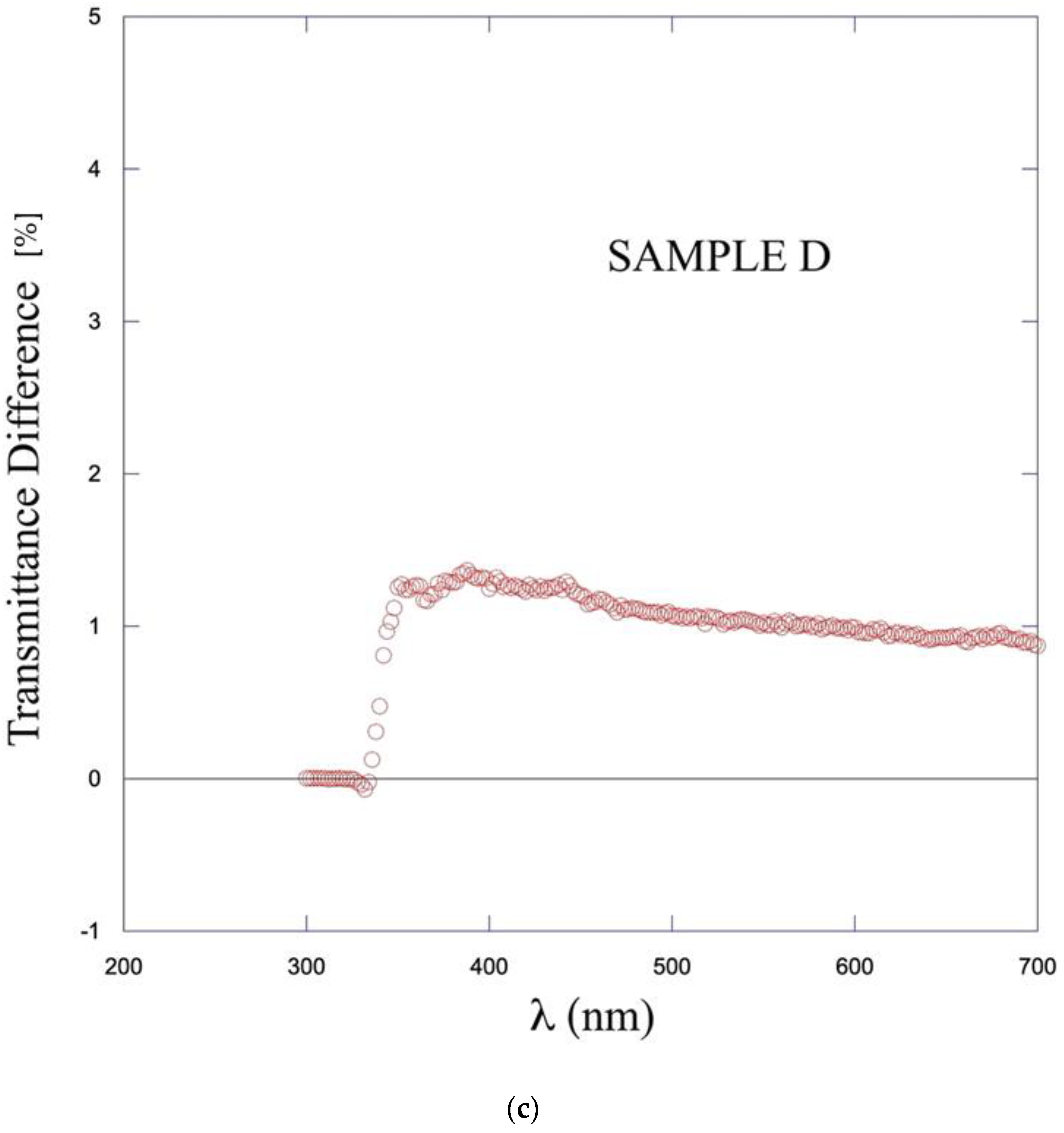
It is known that the light transmittance coefficient of undamaged PWO crystals asymptotically tends to 70% over λ > 350 nm toward λ 650. Figure 7 shows a transmittance spectrum in agreement to this. It is also known that the most relevant part of the radiation damage is located between 350 and 700 nm [1,27,29]. The spectra depicted in Figure 7 confirm that none of our samples underwent radiation damage. On the other hand, the remarkable result is that all three samples underwent a clear improvement in the transmittance coefficient. The spectra before laser pulse treatment (blue lines) have a smaller amplitude with respect to the spectra after pulsed laser irradiation (red line). The results on the three samples systematically show an increase in the transmitted light for all the wavelengths. The enhancement of the transmittance ranges from a few percentage points to about 4%. In all three cases, even if our crystals did not suffer from severe radiation damage but only slight production defects, we observed results consistent with the hypothesis that ultrasonic excitation causes some improvement in optical properties, namely transmittance, in defected crystals. The spectra after laser treatment tend towards the transmittance of undamaged samples, as reported in the literature [1,27,29].
The tests have been carried out on a PWO along its c ^ axis, therefore the characteristics evaluated can eventually change on the other axes due to the anisotropy of the crystal. We have not investigated this aspect yet.

4. Discussion

We have developed a test set-up to perform laser ultrasonics on crystal samples of PWO. The set-up allows us to excite ultrasonic waves in the crystals; we have used it for two purposes: (a) measure the acoustic properties of PWO; (b) assess the hypothesis of ultrasonic recovery of crystal optical transmittance in damaged samples by means of energy deposition caused by pulsed laser radiation.
In this study, we showed the theoretical background of the phenomena, aimed for a complete characterization of the bulk and lattice properties by the means of experiment, and conversely aimed for a fine tuning of the energy and frequency of the ultrasonic waves. Furthermore, these results are a first step towards a complete characterization of the eigen-couples of bulk and lattice vibrations we presented in Section 2.1. It is important to remark that, despite the fact that the phenomena are dissipative in time, we studied a conservative crystal, since the main information on the spectrum can be obtained by simply studying a conservative model.
The speed of sound has been experimentally evaluated for the PWO samples along their c ^ crystallographic axis, allowing the indirect measurement of acoustic impedance Z and the evaluation of the PWO acoustic transmission/reflection coefficients coupled with air. These results deepen the theoretical and experimental knowledge of the mechanical behavior of PWO, providing experimental values for useful mechanical/acoustic parameters.
Then we considered the hypothesis that ultrasonic waves could produce the recovery of crystal defects due to energy deposition. For a first assessment of that hypothesis, we have analyzed the signals acquired in the laser and ultrasonic tests. The results tend to confirm such hypotheses. In fact, considering that the mechanical energy of the wave traveling back and forth is absorbed by the crystal, we see a decaying amplitude.
It is worth noting that the high acoustic impedance of Zc with respect to air is essential to maximize mechanical energy deposition in the crystal. From the calculated transmission/reflection coefficients, (10 and 11) we obtain that 99% of the energy of the impinging acoustic wave is trapped in the sample. In fact, once the crystal is excited by a shock wave, the wave tends to remain in the crystal volume. Therefore, after a short time, the pulse is completely absorbed by the sample. In fact, we evaluated a decay time τ = 8.93 μs (see Section 3.2). This allows us to estimate that the adsorbed energy is about Ea = 99% E = 198 mJ which corresponds to 1.2 × 10¹⁸ eV per pulse.
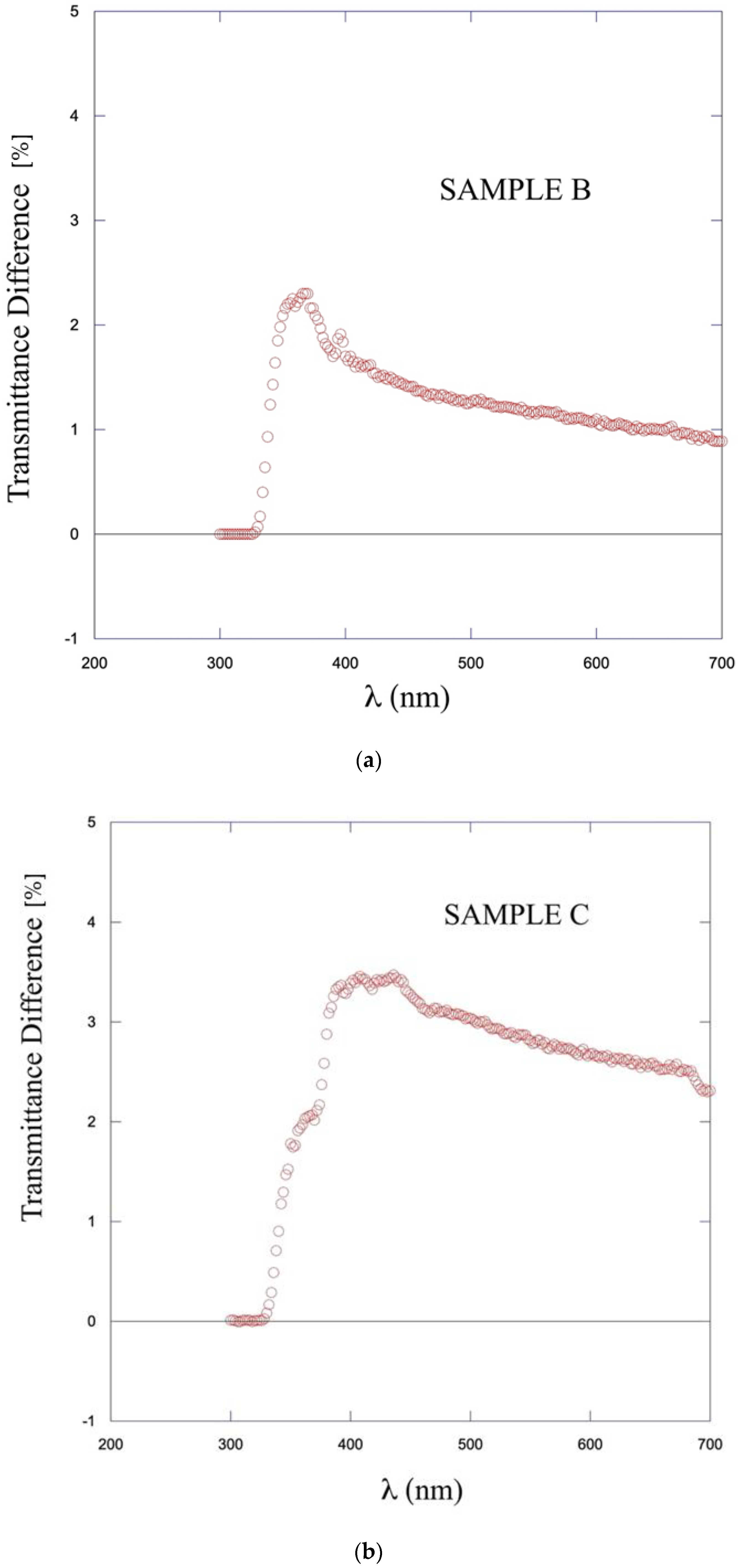
When we measure the optical transmittance spectra before and after the pulsed laser treatment, we observe an improvement for crystals that have slight production (or aging) defects. We did not test samples for radiation damage, which was not available. However, the experimental evidence collected on the three samples of PWO consistently indicates that laser pulses create traveling shock waves at ultrasonic frequency, which are absorbed. These crystals exhibit an increase in transmittance across the spectrum. Therefore, we conclude that the effectiveness of the pulsed laser treatment is shown by an improvement in the transmittance efficiency; each sample has improved the optical performance with different percentage values (Figure 8).
The concept of energy adsorption inducing color center elimination is supported by the fact that the optical transmittance of the PWOs enhances after the treatment in all the samples, supporting the feasibility of a pulsed laser-based recovery tool, that can be fruitful also in the case of radiation damage. This technique should be applied in future tests on samples damaged both by production defects and/or radiation-induced damage. The spectrum of the transmittance difference for all the tested samples is similar (Figure 8), affecting more the shorter wavelength; this would be more in line with a possible radiation recovery since, typically, that kind of damage influences more the cutting edge than the longer wavelength. In fact, Figure 8 puts in evidence that the higher recovery effect is at about λ = 350 nm, in the range where the major radiation damage is located, and moreover, the optical transmittance curve after treatment (Figure 7) reaches the level of the undamaged crystals as reported in the literature also at short wavelength [1,27,29].
The deposited energy may prompt several mechanisms that can cause the transmission variation: so as to promote energy band distortion and/or trapped charge carries to hosts or higher energy bands, but also dislocation and non-equilibrium grain boundary migration, due to ultrasonic excitation. Finally, optical photon absorption can also contribute to the optical improvement [27]. In fact, in these tests, the optical contribution of the pulsed laser is not uncoupled from the mechanical vibration contribution; the separation of the two contributions is our perspective for understanding the specific influence of each. Dedicated systems for testing samples by pure ultrasonic excitation and, separately, by pure optical treatment are under development.
The deposited energy by means of shock waves that make crystal recovery possible is due to dissipative phenomena that can be better explored. They can be explained in terms of released heat, mechanical waves, but also by phonon generation. In this direction, the work is in progress, needing further investigations; however, despite the lack of a complete set of experimentally measured parameters and some theoretical points that still need to be clarified, the feasibility of a device able to deposit mechanical energy in the crystals is confirmed. The knowledge of the complete set of 43 parameters would allow a fine tuning of the laser source aimed at the excitation of the optical frequencies mainly associated with lattice modes rather than the acoustical ones, which are mainly associated with bulk modes.
A complete understanding of the phenomenon needs more investigation, both in an experimental and theoretical direction. Anyway, the tests demonstrate the feasibility of the light transmittance recovery process in a fast and noninvasive way. In fact, the samples surface condition and geometry are not damaged by the test, and no other kind of damage is detected on the samples.
These promising results underline the feasibility of such treatment for transmittance recovery by laser ultrasonic excitation; this stimulates the extension of the tests to other cases, such as irradiated crystals, to deepen the investigation of the energy adsorption mechanisms and test the effectiveness of the methodology.
It is worth remarking that the major advantage of the exposed technique is the possibility to design a cold recovery system without damaging the device and disassembling the measurement electronics system. In fact, the maximum temperature applicable, for instance, in Ecal is 60 °C, making in situ thermal recovery impracticable and needing a higher temperature [28,29]. On the other hand, disassembling the system for crystal recovery by heating would make the operation not economically sustainable.

5. Conclusions

We modeled the crystal as a continuum with a microstructure, which represents the lattice vibrations at a mesoscopic scale; then, for the first time, using the results obtained in [31], we gave a complete characterization of the spectrum in terms of the lattice eigenfunctions. In details, the wave propagation phenomena depend on 43 constitutive parameters and 12 eigenfunctions, which represent the bulk and lattice modes. We gave a complete theoretical description, which should allow for parameter identification by means of aptly designed experiments. Further, once at least a part of these 43 parameters is identified, we can tune the ultrasound waves in order to excite the lattice modes rather than the bulk ones, in order to put most of the initial energy into the samples.
By means of pulsed laser shockwaves, we characterized, for the first time to our best knowledge, the acoustic behavior of PWO (in the c ^ crystallographic direction) by measuring the sound velocity and acoustic impedance. The transmission and reflection indices have been calculated. High impedance favors energy deposition inside the crystals.
Preliminary optical measurements show an increase in light transmittance after the laser shock wave treatment in all the tested samples, although some samples still have some optical damage. This is consistent with the hypothesis that crystal recovery could be achieved by laser radiation.
The preliminary results pave the way for the development of a device for the cold recovery of crystals damaged by high-energy radiation. The pulsed laser radiation generates ultrasonic shock waves, and the traveling ultrasonic energy is mainly absorbed into the crystal volume due to the high acoustic impedance. The suggested set up allows to deposit energy without damaging the crystal and, being at room temperature, is easily applicable without damaging and disassembling the electronic measurement apparatus.

Author Contributions

Conceptualization, L.M.; methodology, L.M. and N.P.; validation data elaboration and analysis D.R., V.D., L.M. and F.D.; formal analysis, F.D.; supervision, N.P., D.R. and V.D. All authors have read and agreed to the published version of the manuscript.

Funding

This research received no external funding.

Acknowledgments

The research leading to these results is within the scope of CERN Experiment RD 18, “Crystal Clear Collaboration.” The authors are grateful to Michel Lebeau, a former CERN member, who taught them the knowledge of crystals.

Conflicts of Interest

The authors declare no conflict of interest.

References

  1. Annenkov, A.A.; Korzhik, M.V.; Lecoq, P. Lead tungstate scintillation material. Nucl. Instrum. Methods Phys. Res. Sect. A Accel. Spectrometers Detect. Assoc. Equip. 2002, 490, 30–50. [Google Scholar] [CrossRef]
  2. Annenkov, A.; Borisevitch, A.; Hofstaetter, A.; Korzhik, M.; Ligun, V.; Lecoq, P.; Missevitch, O.; Novotny, R.; Peigneux, J.P. Improved light yield of lead tungstate scintillators. Nucl. Instrum. Methods Phys. Res. Sect. A Accel. Spectrometers Detect. Assoc. Equip. 2000, 450, 71–74. [Google Scholar] [CrossRef]
  3. Ye, C.; Liao, J.; Shao, P.; Xie, J. Growth and scintillation properties of F-doped PWO crystals. Nucl. Instrum. Methods Phys. Res. Sect. A Accel. Spectrometers Detect. Assoc. Equip. 2006, 566, 757–761. [Google Scholar] [CrossRef]
  4. Lecoq, P.; Annenkov, A.; Gektin, A.; Korzhik, M.; Pedrini, C. Inorganic Scintillators for Detector Systems, Physical Principles and Crystal Engineering, Physical Principles and Crystal Engineering, Series: Particle Acceleration and Detection, XII; Springer: Berlin/Heidelberg, Germany, 2006; ISBN 978-3-540-27768-2. [Google Scholar]
  5. Moreau, J.M.; Galez, P.; Peigneux, J.P.; Korzhik, M.V. Structural characterization of PbWO4 and related new phase Pb7W8O(32−x). J. Alloy. Compd. 1996, 238, 46–48. [Google Scholar] [CrossRef]
  6. Ishii, M.; Harada, K.; Kobayashi, M.; Usuki, Y.; Yazawa, T. Mechanical properties of PbWO4 scintillating crystals. Nucl. Instrum. Methods Phys. Res. Sect. A Accel. Spectrometers Detect. Assoc. Equip. 1996, 376, 203–207. [Google Scholar] [CrossRef] [Green Version]
  7. Baccaro, S.; Barone, L.M.; Borgia, B.; Castelli, F.; Cavallari, F.; Dafinei, I.; De Notaristefani, F.; Diemoz, M.; Festinesi, A.; Leonardi, E.; et al. Ordinary and extraordinary complex refractive index of the lead tungstate (PbWO4) crystal. Nucl. Instrum. Methods Phys. Res. Sect. A Accel. Spectrometers Detect. Assoc. Equip. 1997, 385, 209–214. [Google Scholar] [CrossRef]
  8. Natali, P.P.; Montalto, L.; Daví, F.; Mengucci, P.; Ciriaco, A.; Paone, N.; Rinaldi, D. Theoretical and experimental evaluation of piezo-optic parameters and photoelastic constant in tetragonal PWO. Appl. Opt. 2018, 57, 730–737. [Google Scholar] [CrossRef]
  9. Rinaldi, D.; Daví, F.; Montalto, L. On the photoelastic constants and the Brewster law for stressed tetragonal crystals. Math. Methods Appl. Sci. 2018, 41, 3103–3116. [Google Scholar] [CrossRef]
  10. Natali, P.P.; Montalto, L.; Scalise, L.; Davì, F.; Paone, N.; Rinaldi, D. Fringe modelling and Photoelastic stress Measurement method in tetragonal {PWO} observed in the plane normal to a crystallographic a-axis. J. Instrum. 2020, 15, P09037. [Google Scholar] [CrossRef]
  11. Rinaldi, D.; Ciriaco, A.; Lebeau, M.; Paone, N. Quality control on pre-serial Bridgman production of PbWO4 scintillating crystals by means of photoelasticity. Nucl. Instrum. Methods Phys. Res. Sect. A Accel. Spectrometers Detect. Assoc. Equip. 2010, 615, 254–258. [Google Scholar] [CrossRef]
  12. Montalto, L.; Natali, P.P.; Daví, F.; Mengucci, P.; Paone, N.; Rinaldi, D. Characterization of a defective PbWO4 crystal cut along the a-c crystallographic plane: Structural assessment and a novel photoelastic stress analysis. J. Instrum. 2017, 12, P12035. [Google Scholar] [CrossRef] [Green Version]
  13. Rinaldi, D.; Montalto, L.; Lebeau, M.; Mengucci, P. Influence of a Surface Finishing Method on Light Collection Behaviour of PWO Scintillator Crystals. Photonics 2018, 5, 47. [Google Scholar] [CrossRef] [Green Version]
  14. Mengucci, P.; Di Cristoforo, A.; Lebeau, M.; Majni, G.; Paone, N.; Pietroni, P.; Rinaldi, D. Surface quality inspection of PbWO(4) crystals by grazing incidence x-ray diffraction. Nucl. Instrum. Methods Phys. Res. Sect. A Accel. Spectrometers Detect. Assoc. Equip. 2005, 537, 207–210. [Google Scholar] [CrossRef]
  15. Lebeau, M.; Gobbi, L.; Majni, G.; Paone, N.; Pietroni, P.; Rinaldi, D. Mapping residual stresses in PbWO4 crystals using photo-elastic analysis. Nucl. Instrum. Methods Phys. Res. Sect. A Accel. Spectrometers Detect. Assoc. Equip. 2005, 537, 154–158. [Google Scholar] [CrossRef]
  16. Ciriaco, A.; Daví, F.; Lebeau, M.; Majni, G.; Paone, N.; Pietroni, P.; Rinaldi, D. PWO photo-elastic parameter calibration by laser-based polariscope. Nucl. Instrum. Methods Phys. Res. Sect. A Accel. Spectrometers Detect. Assoc. Equip. 2007, 570, 55–60. [Google Scholar] [CrossRef]
  17. The CMS Collaboration. The Electromagnetic Calorimeter Technical Design Report CERN/LHCC 97-033; CERN: Geneva, Switzerland, 1997; Volume 4. [Google Scholar]
  18. Auffray, E.; Lecoq, P.; Paoletti, S.; Sempere, P.; Vigo, E.; Schneegans, M. Status of PbWO-4 crystals R\&D and preproduction from BTCP for the CMS calorimeter. Nucl. Phys. B Proc. Suppl. 1999, 78, 197–202. [Google Scholar] [CrossRef]
  19. The CMS Collaboration. CMS, the Compact Muon Solenoid: Technical Proposal; Report Number “CERN-LHCC-94-38, CERN-LHCC-P-1”; CERN: Geneva, Switzerland, 1994. [Google Scholar]
  20. Arduini, G.; Barranco, J.; Bertarelli, A.; Biancacci, N.; Bruce, R.; Brüning, O.; Buffat, X.; Cai, Y.; Carver, L.R.; Fartoukh, S.; et al. High Luminosity LHC: Challenges and plans. J. Instrum. 2016, 11, C12081. [Google Scholar] [CrossRef]
  21. Apollinari, G.; Bejar Alonso, I.; Bruning, O.; Lamont, M.; Rossi, L. High-Luminosity Large Hadron Collider (HL-LHC): Preliminary Design Report; CERN Yellow Reports: Monographs; CERN: Geneva, Switzerland, 2015. [Google Scholar]
  22. Erni, W.; Keshelashvili, I.; Krusche, B.; Steinacher, M.; Heng, Y.; Liu, Z.; Liu, H.; Shen, X.; Wang, Q.; Xu, H.; et al. Technical design report for the PANDA (AntiProton Annihilations at Darmstadt) Straw Tube Tracker. Eur. Phys. J. A 2013, 49, 25. [Google Scholar] [CrossRef] [Green Version]
  23. Novotny, R.W.; Bremer, D.; Dormenev, V.; Drexler, P.; Eissner, T.; Kuske, T.; Moritz, M. High-quality PWO crystals for the PANDA-EMC. J. Phys. Conf. Ser. 2011, 293, 012003. [Google Scholar] [CrossRef]
  24. Ikegami Andersson, W. The PANDA Detector at FAIR. J. Phys. Conf. Ser. 2016, 770, 012043. [Google Scholar] [CrossRef] [Green Version]
  25. Boca, G. The PANDA experiment: Physics goals and experimental setup. EPJ Web Conf. 2014, 72, 2. [Google Scholar] [CrossRef] [Green Version]
  26. Barysevich, A.; Dormenev, V.; Fedorov, A.; Glaser, M.; Kobayashi, M.; Korjik, M.; Maas, F.; Mechinski, V.; Rusack, R.; Singovski, A.; et al. Radiation damage of heavy crystalline detector materials by 24GeV protons. Nucl. Instrum. Methods Phys. Res. A 2013, 701, 231–234. [Google Scholar] [CrossRef]
  27. Borisevitch, A.E.; Dormenev, V.I.; Fedorov, A.A.; Korjik, M.V.; Kuske, T.; Mechinsky, V.; Missevitch, O.V.; Novotny, R.W.; Rusack, R.; Singovski, A.V. Stimulation of radiation damage recovery of lead tungstate scintillation crystals operating in a high dose-rate radiation environment. IEEE Trans. Nucl. Sci. 2013, 60, 1368–1372. [Google Scholar] [CrossRef]
  28. Auffray, E.; Korjik, M.; Singovski, A. Experimental study of lead tungstate scintillator proton-induced damage and recovery. IEEE Trans. Nucl. Sci. 2012, 59, 2219–2223. [Google Scholar] [CrossRef] [Green Version]
  29. Adzic, P.; Almeida, N.; Andelin, D.; Anicin, I.; Antunovic, Z.; Arcidiacono, R.; Arenton, W.; Auffray, E.; Argiro, S.; Askew, A.; et al. Radiation hardness qualification of PbWO4 scintillation crystals for the CMS Electromagnetic Calorimeter. J. Instrum. 2010, 5, P03010. [Google Scholar] [CrossRef] [Green Version]
  30. Millers, D.; Grigorjeva, L.; Chernov, S.; Popov, A.; Lecoq, P.; Auffray, E. The temperature dependence of scintillation parameters in PbWO4 crystals. Phys. Stat. Sol. 1997, 203, 585–589. [Google Scholar] [CrossRef]
  31. Daví, F. Wave propagation in micromorphic anisotropic continua with an application to tetragonal crystals. Math. Mech. Solids 2020, 26, 804–822. [Google Scholar] [CrossRef]
  32. Born, M.; Huang, K. Dynamical Theory of Crystal Lattices; Clarendon Press: Oxford, UK, 1998; ISBN 9780198503699. [Google Scholar]
  33. Capriz, G. Continua with Microstructure; Springer: New York, NY, USA, 1989; ISBN 978-1-4612-3584-2. [Google Scholar]
  34. Scalise, L.; Rinaldi, D.; Davì, F.; Paone, N. Measurement of ultimate tensile strength and Young modulus in LYSO scintillating crystals. Nucl. Instrum. Methods Phys. Res. Sect. A Accel. Spectrometers Detect. Assoc. Equip. 2011, 654, 122–126. [Google Scholar] [CrossRef]
  35. Rothberg, S.J.; Allen, M.S.; Castellini, P.; Di Maio, D.; Dirckx, J.J.J.; Ewins, D.J.; Halkon, B.J.; Muyshondt, P.; Paone, N.; Ryan, T.; et al. An international review of laser Doppler vibrometry: Making light work of vibration measurement. Opt. Lasers Eng. 2017, 99, 11–22. [Google Scholar] [CrossRef] [Green Version]
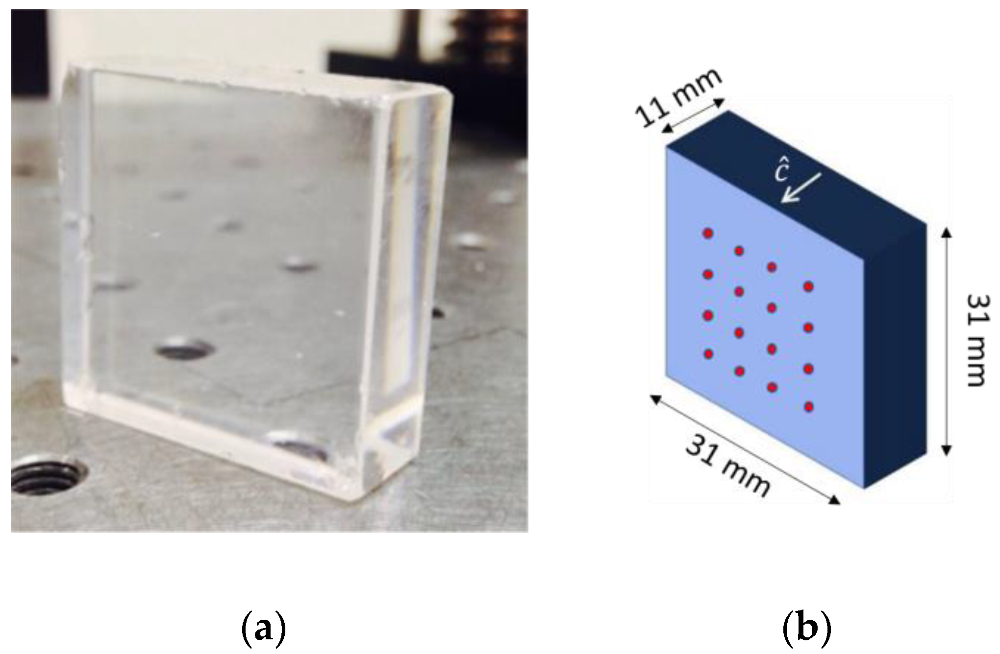
Figure 1. (a) the typical PWO sample (b) the scheme of the sample geometry and the area on which the laser pulses are shot (red dots). The dots indicate the points where the pulsing laser impinges. The arrow is representing the c ^ axis direction.
Crystals 13 00556 g001
Figure 2. The experimental layout. The pulsed laser controller triggers both the laser and the acquiring oscilloscope.
Crystals 13 00556 g002
Figure 3. Expected signal, A is the amplitude as a function of the time t: First arrive of the wave and the n reflection (the wave travels two times the sample thickness).
Crystals 13 00556 g003
Figure 4. Laser vibrometer displacement following a laser pulse. The detected signal is measured in arbitrary unit. The principal signal and the subsequent reflections are highlighted by the red circles. In the figure, a strong initial peak is clearly recognizable at time equal to 0 s, it is maybe due to electromagnetic noise.
Crystals 13 00556 g004
Figure 5. The wave path inside and outside (air) the sample. The wave, indicated by the red arrow, travels normally to the interfaces.
Crystals 13 00556 g005
Figure 6. In the graph (on the left), the normalized wave pulse amplitude A (a.u. normalized) is displayed. On the right, is shown the length crossed by the wave, considering the evaluated sound speed inside the crystal. On the left, the pulse decay is reported as a function of time, on the right the displacement in a function of time.
Crystals 13 00556 g006
Figure 7. Transmittance percentage (%), measured before (blue points) and after (red points) the treatment as a function of the light wavelength. The transmittance improvement is evident in all the range.
Crystals 13 00556 g007aCrystals 13 00556 g007b
Figure 8. The difference of the transmittance percentage value after and before the treatment is showed in the graphs. The increment is higher for the sample C. The lowest values are for the sample D. The recovery for the all the samples seems to have the same behaviour, affecting more to short wavelength. This would be more in line with a possible radiation damage recovery.
Crystals 13 00556 g008aCrystals 13 00556 g008b
Disclaimer/Publisher’s Note: The statements, opinions and data contained in all publications are solely those of the individual author(s) and contributor(s) and not of MDPI and/or the editor(s). MDPI and/or the editor(s) disclaim responsibility for any injury to people or property resulting from any ideas, methods, instructions or products referred to in the content.