Article

Investigation of the Influence of High-Pressure Torsion and Solution Treatment on Corrosion and Tribocorrosion Behavior of CoCrMo Alloys for Biomedical Applications

1
Department of Metallurgical and Materials Engineering, Yildiz Technical University, Istanbul 34220, Turkey
2
Health Biotechnology Joint Research and Application Center of Excellence, Esenler, Istanbul 34220, Turkey
3
Center for MicroElectro Mech. Systems (CMEMS-UMinho), University of Minho, 4800-058 Guimarães, Portugal
4
International Iberian Nanotechnology Laboratory, Av. Mestre José Veiga s/n, 4715-330 Braga, Portugal
5
Department of Metallurgical and Materials Engineering, Ataturk University, Erzurum 25240, Turkey
6
Department of Materials Science and Engineering, Izmir Institute of Technology, Izmir 35430, Turkey
7
European Branch of the Institute of Biomaterials, Tribocorrosion and Nanomedicine (IBTN/Euro), University of Minho, 4800-058 Guimarães, Portugal
8
Associate Laboratory on Biotechnology and Bioengineering, and Electromechanical Systems (LABBELS), University of Minho, 4800-058 Guimarães, Portugal
9
Automotive Engineering Department, Bursa Uludag University, Bursa 16059, Turkey
10
Institute for Materials Research, Tohoku University, Sendai 980-8577, Japan
11
Graduate School of Engineering, Osaka University, Osaka 565-0871, Japan
12
Department of Materials Science and Engineering, Meijo University, Nagoya 468-8502, Japan
13
Faculty of Chemistry, Materials and Bioengineering, Kansai University, Osaka 564-8680, Japan
14
Department of Mechanical Engineering, Kindai University, Osaka 577-8502, Japan
*
Authors to whom correspondence should be addressed.
Crystals 2023, 13(4), 590; https://doi.org/10.3390/cryst13040590
Submission received: 2 March 2023 / Revised: 16 March 2023 / Accepted: 22 March 2023 / Published: 30 March 2023
(This article belongs to the Section Inorganic Crystalline Materials)

Abstract

:
In this study, the influence of the high-pressure torsion (HPT) processing parameters and solution treatment (ST) on the corrosion and tribocorrosion behavior of CoCrMo (CCM) alloys was investigated for possible usage in biomedical applications. The corrosion behavior of the CCM alloys was investigated by using potentiodynamic scanning (PDS) and electrochemical impedance spectroscopy (EIS) tests. Tribocorrosion tests were carried out in a reciprocating ball-on-plate tribometer at 1 Hz, 1 N load, and 3 mm stroke length for 2 h. All electrochemical measurements were performed using a potentiostat in standard phosphate-buffered saline (PBS) solution at body temperature (37 ± 2 °C). The samples were characterized by using a scanning electron microscope (SEM), transmission electron microscope (TEM), optical microscope (OM), and X-ray diffraction (XRD). The deepness and width of wear tracks were examined by using a profilometer. The results showed that HPT and ST processes did not affect significantly the corrosion resistance of samples. However, the ST-treated samples had a higher material loss during sliding in standard phosphate-buffered saline (PBS) at body temperature as compared to HPT-treated samples.

1. Introduction

When using a biomaterial that will be considered foreign to the body, one of the most critical issues is undoubtedly the biocompatibility of the implant candidates [1]. Thus, the studies to improve both bulk and surface properties of biomaterial candidates continue, and different surface coating techniques, heat treatments, or thermomechanical processes are widely used to achieve this purpose [2,3,4,5].
It is well known that 316L, Ti alloys, and CoCrMo (CCM) alloys are the most widely used metal-based biomaterials [1]. However, 316L stainless orthopedic implants have been mainly replaced with Ti or CCM alloys due to their superior mechanical and biocompatibility properties. Compared to other candidates commonly used as metallic implant materials, CCM alloys have a wide range of applications in the hip and knee joints, especially in their sliding parts, such as the femoral head and acetabular cup, due to their good biocompatibility performance, high hardness and mechanical properties, nobler structure in the body environment, and good wear resistance [6,7,8,9]. In addition, CCM alloys also show high corrosion resistance due to the natural Cr2O3 layer formed on their surfaces [10]. The CCM alloys have attractive properties as a prosthetic implant material due to their rigidity and resistance to abrasion and corrosion. It is well known that Cr induces the formation of protective oxide film and progresses the corrosion resistance of CCM alloys. Mo is generally used for grain refinement and to increase the strength and fatigue resistance of CCM alloys [11].
These protective oxide films are stable under aggressive conditions containing Cl such as in the body environment. However, it has become a necessity to improve the surface and bulk properties of CCM alloys due to metal loss induced by wear debris nowadays [12]. The wear debris leads to increased local tissue inflammation and may cause toxicity or allergies in the body and affect the implant’s corrosion resistance [12]. Thus, there is a need to understand CoCrMo alloys better.
The tribocorrosion behavior of biomaterials is a complex process because it operates in an aggressive environment and under relative loadings. When a material is implanted in the body, the co-operative effect of corrosion and wear processes causes a tribocorrosion phenomenon [9,13]. The prosthesis’ failure has mainly resulted from fatigue, wear, break, corrosion, and inflammations according to published reports [14]. The protective passive film on the implant alloy cracks due to the synergetic effect of corrosion and wear [15,16,17,18].
The corrosion and tribocorrosion behavior of CCM has been studied in recent studies [19,20,21,22,23,24,25]. These studies examined the different CCM alloys obtained by different production methods in body conditions at body or room temperature to explain corrosion or tribocorrosion behavior.
Doni et al. [20] compared the tribo-electrochemical behavior of hot-pressed CoCrMo alloy with commercial cast CoCrMo in 8 g·L−1 NaCl solution. The results showed that the processing route did not create a significant difference in either on the corrosion behavior or the wear rate of the CoCrMo alloy. F. Renn et al. [19] studied ultrafine-grained CCM alloy in a simulated physiological solution (SPS) at room temperature and, also, the wear resistance of this alloy was examined. This study showed that ultrafine-grained CCM alloys presented better corrosion behavior and wear resistance than conventional CCM ones.
Recent studies [26,27] about conventional processes such as solution treatment and cold rolling for metallic biomaterials have reported that these conventional processes do not give a promising improvement in the mechanical properties [28]. Solution treatment and cold rolling are not good enough to improve the mechanical properties of CoCrMo alloys and alternative methods are required. At this point, severe plastic deformation (SPD) appears to be an effective method for obtaining exceptional properties.
Recent developments in production methods have shown that bulk materials’ mechanical and physical properties can be extraordinarily improved by severe plastic deformation techniques [29]. There are different SPD techniques, such as equal channel angular pressing (ECAP), high-pressure torsion (HPT), cycling extrusion–compression (CEC), accumulative roll-bonding (ARB), severe torsion straining (STS), or multi-axial forging (MAF) [30,31]. The latest studies showed that one of the most effective ways to provide ultrafine grains and extra-high dislocation density in bulk materials was the HPT [32,33]. The HPT process is performed by applying rotation under pressure to the disk-like sample placed between the opposing anvils [34,35].
In order to create various crystallographic structures and grain sizes in a CCM alloy, HPT was used by Namus et al. [36]. The effect of grain size on corrosion and tribocorrosion behavior was investigated. The results demonstrate a decrease in the corrosion resistance for the HTP-processed samples. The corrosion current (Icorr) values of the as-cast CCM alloy increased with the HPT rotation number (from 1 to 5) but there was no observed significant change in the corrosion potential (Ecorr) values of the samples. The authors expressed that the formation of a less resistant oxide layer due to the finer grains in the structure after the HPT process may be the reason for the increase in Icorr. However, the results showed that the grain size has just a minimal effect on tribocorrosion contribution.
The CCM alloys subjected to HPT have ultrafine/nano-grained (UF/NG) microstructure and exceptional mechanical properties. Isik et al. [37] studied CCM alloys subjected to HPT and they reported that these materials have ultrafine/nano-grained microstructure by using SEM and XRD analysis. Due to these mechanical properties and microstructures, better corrosion and tribocorrosion behavior can be expected from CCM alloys subjected to HPT. For this reason, CCM alloys subjected to HPT can be alternative materials for biomedical applications. The situation of these samples provides a good motivation for researchers who study ultrafine/nano-grained CCM alloys.
In addition, recent studies on nano-grained CCM alloys obtained by the HPT process have often been based on the microstructure and simple mechanical properties of these materials. However, the absence of corrosion and tribocorrosion behavior of NG biomedical CCM obtained by HPT has been seen as a major deficiency in the literature. So, this study was conducted to investigate the influence of the HPT processing parameters and heat treatment on the corrosion and tribocorrosion behavior of a CCM alloy used for biomedical applications.

2. Experimental Procedure

2.1. Material

In this study, the cylindrical hot-forged CoCrMo alloy (ASTM F799) was used with 25 mm diameter and 50 mm length. The chemical composition of the samples is listed in Table 1. The solution treatment was applied at 1473 K for 3.6 ks in a vacuum for hot-forged samples (hereafter named as CCMST).

2.2. High-Pressure Torsion (HPT) Processes

The CCMST samples were machined to obtain 10 mm diameter and 1 mm thickness as a coin-shaped HPT sample (named CCMHPT). HPT process was applied for coin-shaped samples with 6 GPa pressure and 0.2 rpm rotation rate at room temperature, shown in Figure 1. MoS2 was used as a lubricant during the HPT process. For HPT processing, 0.25 and 5 rotation numbers (RN) were used and the samples were described as CCMHPT0.25 and CCMHPT5, respectively. Short-time solution treatment was conducted at 1273 K for 0.3 ks for some samples with a 0.25 rotation number (CCMHPT0.25-st). Thus, after the process, four different test groups (CCMST, CCMHPT0.25, CCMHPT5, and CCMHPT0.25-st) were obtained.
In this study, the above 4 samples were selected to investigate their corrosion and tribocorrosion behaviors. Microstructural evolution and mechanical behaviors of the CCM alloy subjected to the HPT processing were studied at various conditions, such as HPT and heat treatment parameters, in our previous studies [27,37,38,39]. In these studies, CCM alloy was subjected to HPT processing by selecting different rotation numbers. The most advanced mechanical properties were obtained when the CCM applied a rotation number (N) of 0.25 and 1 turn [39], since an increase in rotation number gives rise to a decrease in the volume fraction of the ε phase. On the other hand, a reverse ε to γ phase transformation occurrence is suggested when the grain size is further refined to a nanometer scale [40,41,42,43,44]. Grain boundaries become more equiaxed with an increasing number of rotations at N = 5, while a more complicated microstructure with less defined grain boundaries appears at N = 0.25 [37]. Moreover, dislocation density decreases with increasing rotation number after 1 revolution [39], which is one of the possible reasons beyond the decrease in strength after rotation number 1 among HPT conditions. Thus, a short-time solution treatment was conducted on CCMHPT0.25-st sample.

2.3. In Vitro Corrosion Tests

Before the corrosion and tribocorrosion tests, the samples were ground using SiC papers down to 2400 grit. Then, the samples were cleaned by ultrasonic cleaner for 10 min in propanol and 5 min in distilled water, respectively. Finally, the samples were kept in a desiccator for 24 h before starting the tests to obtain a similar sample surface.
Open-circuit potential (OCP), potentiodynamic scanning (PDS), and electrochemical impedance spectroscopy (EIS) tests were carried out as electrochemical corrosion tests. Phosphate-buffered saline (PBS; 0.2 KCl, 0.24 KH2PO4, 8 NaCl, 1.2 Na2HPO4 in g·L−1) solution was selected as an electrolyte and all corrosion tests were carried out at body temperature (37 ± 2 °C) with a potentiostat/galvanostat (Gamry, Reference-600+, Warminster, PA, USA). A three-electrode system was used for corrosion tests with 150 mL electrolyte volume. A saturated calomel electrode (SCE) was selected as a reference electrode, a platinum (Pt) electrode was selected as a counter electrode, and the prepared samples having an exposed area of 0.38 cm2 were used as a working electrode. An OCP test was carried out for 3 h to stabilize the surface of the samples. After stabilizing surfaces, EIS measurements were performed by scanning frequencies from 100 kHz to 10 mHz with 7 points per frequency decade. The sinusoidal amplitude was set as 10 mV to guarantee linearity of the electrode response. After EIS tests, potentiodynamic polarization tests were carried out between 0.25 V below OCP and 1.0 V versus SCE in an anodic direction with a scanning rate of 0.5 mV·s−1.

2.4. Tribocorrosion Tests

Tribocorrosion tests were carried out in a reciprocating ball-on-plate tribometer (CETR-UMT-2). An electrochemical cell was installed on the tribometer and the samples were used as working electrodes having a 0.785 cm2 exposed area. Therefore, all data have been normalized according to the surface area. An alumina (Al2O3) ball (10 mm diameter, Ceratec) was used as a counter-material. All tribocorrosion tests were performed using PBS solution (30 mL) at body temperature (37 ± 2 °C). The electrochemical tests were performed using a potentiostat/galvanostat (Gamry, Reference-600). All tribocorrosion tests were carried out under OCP. OCP was monitored before (to stabilize the sample surface), during, and after sliding (to observe the repassivation of the sample surface). Linear polarization (LP) was also measured at ±20 mV with 1 mV·s−1 scanning rate for every 20 min before, during, and after sliding to assess the evolution of Icorr. The sliding was performed for 2 h and, after sliding, the OCP was recorded for 10 min. The tribological parameters were used as the frequency of 1 Hz, the normal load of 1 N, and the total stroke length of 3 mm.
After the corrosion and tribocorrosion tests, the samples were cleaned by an ultrasonic cleaner for 10 min in propanol and 5 min in distilled water for microstructural observations. Moreover, the wear tracks’ deepness and width were examined using a profilometer (Veeco, Dektak 150, Plainview, NY, USA), and then the wear volumes were calculated using the procedure given elsewhere [20].

2.5. Characterizations

The tested surfaces were examined using a scanning electron microscope (SEM, Zeiss Sigma 300). Transmission electron microscope (TEM, TOPCON EM-002B) observations were carried out with an accelerating voltage of 200 kV. Wear tracks were characterized using an optical microscope (OM) and image analysis software (Image J 1.37v). X-ray diffraction (XRD, PANalytical Empyrean) was used to determine the formed phases during the HPT. In addition, the hardness measurements were carried out using a Vickers microhardness tester with a load of 4.9 N for a dwell time of 15 s on the surface of the specimens. However, due to the nature of the HPT process, the deformation rate varied radially from the center to the outer edges of the sample, resulting in a corresponding radial variation in hardness. Therefore, the average surface hardness values of the samples were presented in this study.

3. Results and Discussion

The XRD analysis of the samples is presented in Figure 2. It is seen that the CCMST sample has mostly γ(fcc)-phase structure. After the HPT treatment, the ε phase was densely formed in the structure and the γ phase. It is noteworthy that the ε(hcp) phase in the structure increases with the increase in deformation rate (RN was changed from 0.25 to 5). In addition, a peak broadening and shift were observed in the XRD patterns after HPT treatment of samples compared to the CCMST structure. The volume fraction of ε phase in the microstructure increases with an increase in rotation number from 0.25 to 5, attributed to the increase in the mechanical properties and refinement of grains [45,46,47].
Figure 3 shows the TEM analysis and the diffraction patterns of the samples. The diffraction patterns provided dominant γ phase in the ST-treated samples. The CCMST samples had equiaxed grains with micron size and random orientation. In addition, some twinning is clearly shown in these samples due to the ST process (CCMST and CCMHPT0.25-st in Figure 3). The HPT samples had nanosized grains, dislocations exhibited blurred wavy morphology, and grain boundaries were not fully observed. The diffraction patterns of the HPT samples indicated a heterogeneous pattern (CCMHPT0.25 and CCMHPT5 in Figure 3). Rings in the patterns indicate that the structure in these samples is at the submicron or nano size scale [40]. Each Debby ring corresponds to a specific crystal plane defined in the XRD patterns (Figure 2). This indicates grain refinement after the HPT process in the microstructure. Our previously published studies have investigated the phase formation and transformation mechanism of the CCM alloys through high-pressure torsion detailly [27,37,38].
The PDS curves generated from CCM samples tested in PBS solution at body temperature are presented in Figure 4 comparatively. In addition, the open-circuit potential (Eocp), corrosion potential (Ecorr), passivation current density (ipass), and breakdown potential (Ebd) values extracted from the curves are collected with their reproducibility variations in Table 2.
The polarization curves can be divided into four different regions for examination. These regions are cathodic, transition, passive, and transpassive zones, respectively, as they have already been reported for CCM biomedical alloy [48]. The samples have a similar cathodic domain, and the cathodic domain and the currents are determined by the reduction of water and partially dissolved oxygen [49]. The corrosion potential (Ecorr) of samples includes between −0.4 and −0.1 V, which is characterized by the transition from cathodic to anodic current, except for the CCMHPT5 test group. This group has a slightly smaller transition area than the other three test groups.
According to PDS curves in Figure 4, CCM samples show similar polarization curves and corrosion behavior. There are no significant differences between corroded samples. In the anodic domain, all CCM sample groups include a similar passivation plateau because of passive film formation. After the passivation plateau, all samples presented a breakdown potential around 0.42 V, indicating the initiation of dissolution of the passive film. As shown in Figure 4, the passivation current density was also observed to be similar and the potential range for passive behavior was approximately 0.25 V to 0.4 V vs. SCE throughout all samples. The breakdown potentials (Ebd) for anodic oxide breakdown (approximately 0.4 V vs. SCE) were consistently seen for all samples. Secondary passivity was present in all samples at 0.6 V versus SCE. Figure 5 shows preferential dissolution on all conditions except for CCMHP5 due to its finer structure.
It was seen that the protective oxide layer was abrupted after the secondary passivity. The PBS is stagnant in the abrupted regions and prevents the oxygen entering in these areas. Consequently, the corrosion products are filled in these areas. The high positive charge concentration in the filled areas will attract the negatively charged ion, such as Cl in the PBS. So, the negatively charged concentration will increase in these areas. These areas show preferentially higher solubility in the oxide film. Thus, quick and in-depth corrosion will continue under the products (Figure 6). This type of corrosion is known as localized. A similar propagation mechanism was also observed in all samples (Figure 6).
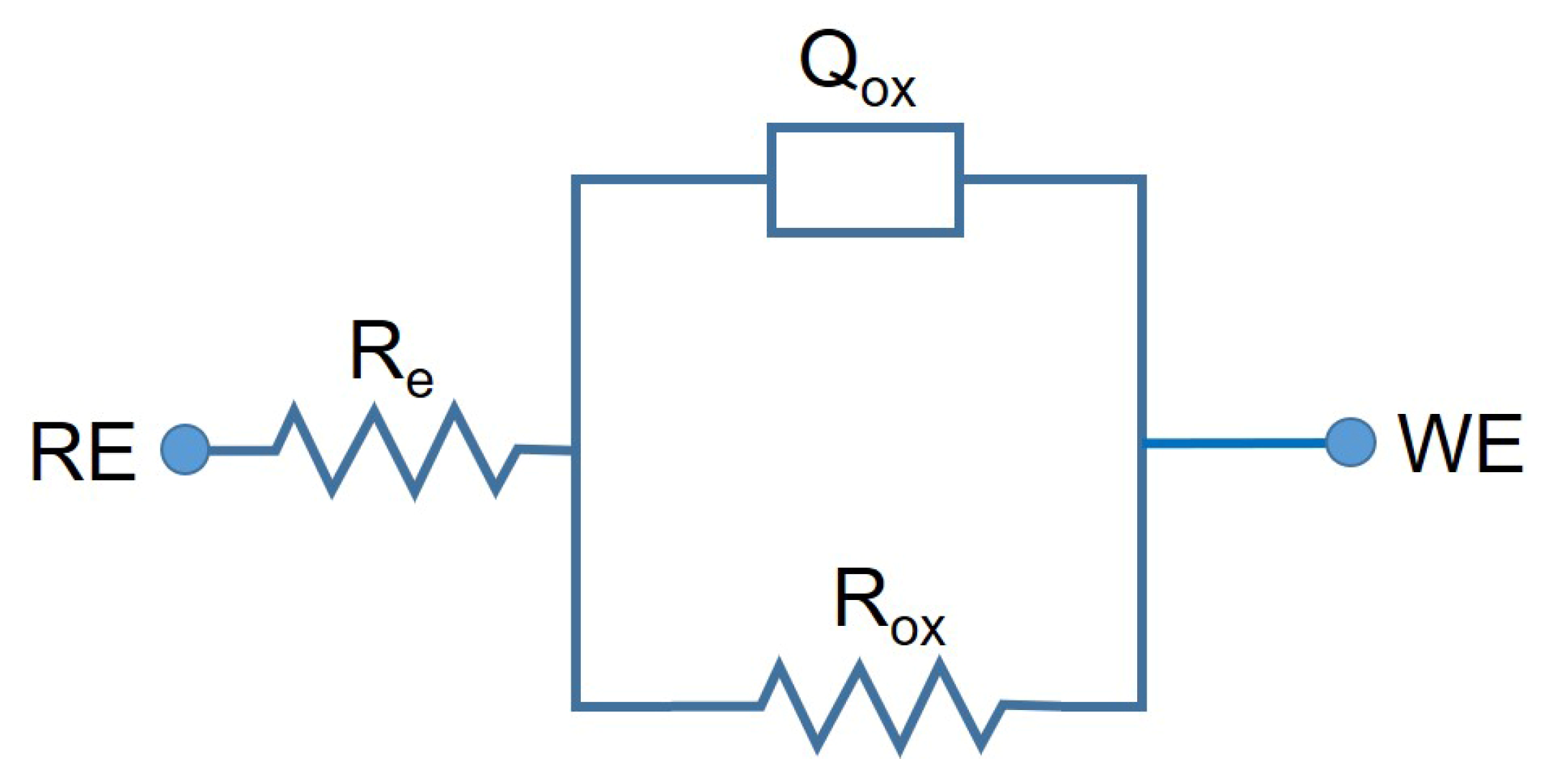
Nyquist and Bode plots of the tested samples are presented in Figure 7 with fitted data and Rox and Cox in Table 3 according to the equivalent circuit used for CCM samples shown in Figure 8.
The impedance spectra were fitted to the electrical equivalent circuit (EEC) using Z-View software (version 2.9) by evaluating the quality of fitting through their chi-square (χ2) values. The native oxide film formed on surfaces of CCM samples contains electrolyte resistance, Re, native oxide film resistance (passive film), Rox, and constant phase element (CPE), Qox, considering the nonideal capacitance of the native oxide film is presented by the EEC in Figure 9 [50]. EEC parameters are presented in Table 3 for CCM samples obtained from EIS data. C (capacitance) was used instead of Q. Cox values were converted to Qox by using Equation (1) derived from Brugg’s equation [50].
C o x = [ Q o x R e ( 1 n ) ] 1 n
The kinetics and quality of the passive film are examined by using Bode diagrams. According to the Bode diagrams, the results show no significant difference between the passive film of sample groups. As fitting parameter results of samples (Rox and Cox) show, no significant difference is obtained from all sample groups. A quantity of passive film’s polarization resistance that determines corrosion resistance is obtained from Nyquist diagrams. Moreover, as a function of the applied frequency perturbation, the real and imaginary parts of the impedance are represented by Nyquist diagrams. In the EIS diagrams, the semi-circular arc can be compared for each group and, according to this comparison, the corrosion properties of test groups can be evaluated [51]. As can be seen, the corrosion resistance of CCMHPT0.25-st is slightly better than other test groups according to a comparison of the semi-circular arc of samples. Finally, when all corrosion results are considered, the HPT and ST processes did not significantly affect the corrosion resistance and corrosion behavior of samples. As can be seen from corrosion results, before and after HPT and ST, all samples show similar corrosion behavior and corrosion resistance in PBS solution at body temperature.
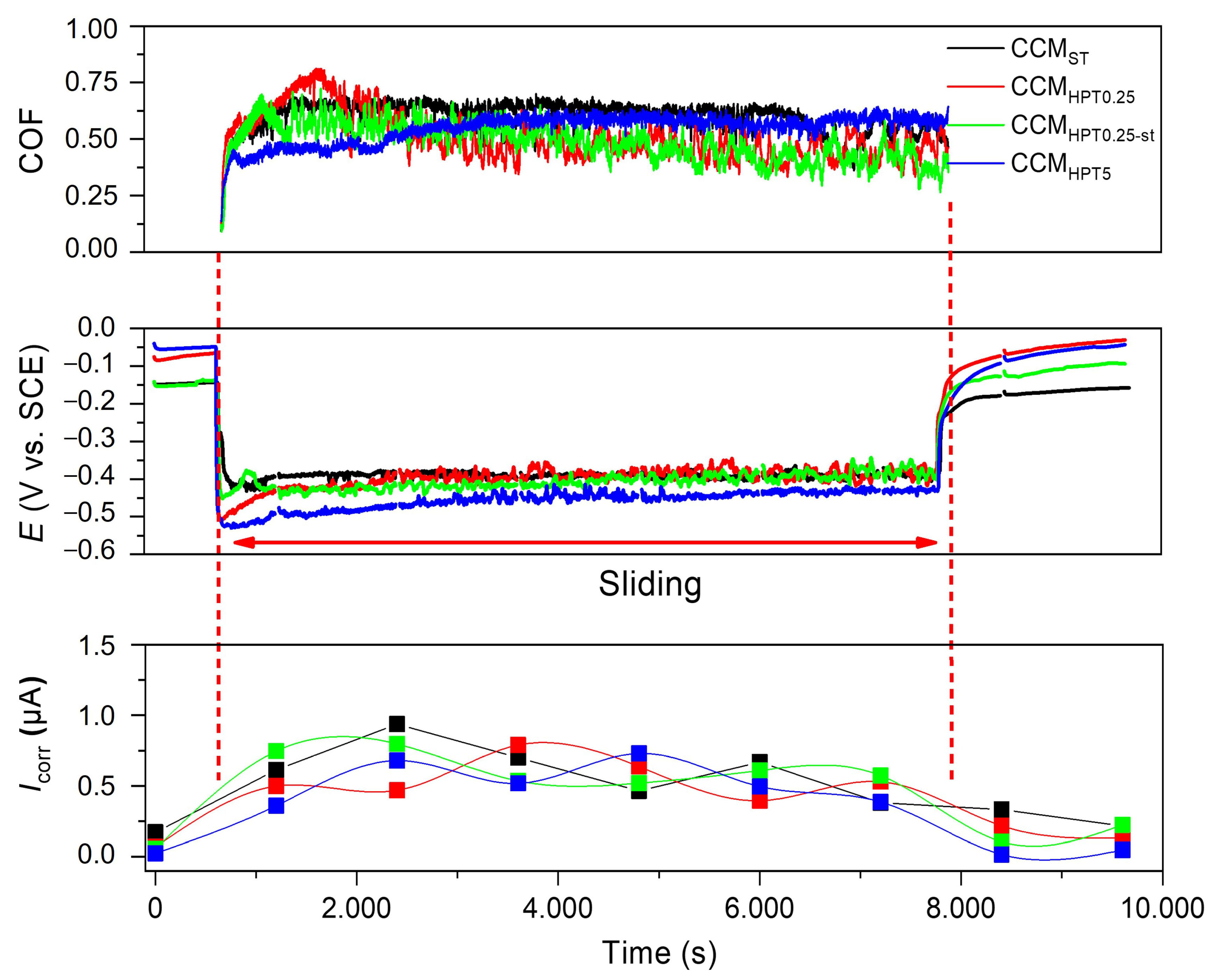
Figure 9 illustrates the changes in OCP, Icorr before, during, and after sliding, as well as the coefficient of friction (COF) during sliding in PBS solution at body temperature.
All tested groups presented similar COF values and COF evolution. The COF values of all samples are around 0.6. The COF values of CCMST and CCMHPT5 test groups have more minor oscillations than CCMHPT0.25 and CCMHPT0.25-st test groups. The COF values of these samples changed between 0.5 and 0.7 with the effect of these oscillation values. This oscillation difference in COF between all test groups may be due to the hardness distribution of samples. Prior to HPT process, the hardness of the CCMST sample was around 300 HV. However, after HPT, both the grain refinement that occurred in the microstructure and the increased density of martensite and dislocations caused the overall hardness of the samples to increase to approximately 500–550 HV [37,39]. In our previous studies, the hardness distributions have been reported [27,38,39] in the same samples. According to these hardness results, CCMST and CCMHPT5 test groups have more homogenous hardness distributions than other groups. These hardness homogeneities of the CCMST and CCMHPT5 in their structure of samples may cause more minor oscillations on the COF graphs. On the other hand, the increase in hardness values of samples by HPT did not have a noticeable influence on the COF values.
Three different zones were observed during the evolution of OCP. The constant OCP values recorded before sliding indicated the formation of a passive film on sample surfaces. As soon as sliding started, a sharp drop into the cathodic direction was observed, indicating the passive film’s destruction. The effect of mechanical damage led to the formation of active zones on the worn area. Lower potential values recorded during sliding indicated a higher tendency towards corrosion for all CCM test group samples. The recorded oscillations during sliding were related to the depassivation and repassivation phenomena. If OCP values of test group samples are compared, HPT and ST did not cause a significant difference in the OCP values of samples for all test groups. As can be seen, all OCP values of samples for all test groups have similar OCP evolution. However, to better understand the tribocorrosion behavior, the corrosion kinetics under sliding also need to be studied.
The evolution of Icorr for before, during, and after sliding is also presented in Figure 10. Like OCP values, three different zones were observed during the evolution of Icorr. Before sliding, current values have lower values because of formation of the passive film. As soon as sliding started, the current values obtained higher values. Since alumina balls destroyed the passive films by mechanical damage, the effect of mechanical damage led to the formation of active zones on the worn area and the corrosion rate of samples obtained a higher level. Due to this destruction of the passive film, the current values of samples obtained higher levels. During sliding, the current values were relatively similar for each Icorr stage, as shown in Figure 9, which means a decrease in the flow of electrons consumed in regrowing the film. As soon as sliding is finished, the current values obtained a lower level as before sliding because of the reformation of the passive film. After sliding, the current values were stable because of the passive film and covering of the active zone on worn surfaces.
The wear track profiles, wear volumes, and the OM images of the wear tracks of CCM samples are presented in Figure 10. As can be seen, the CCMHPT0.25-st samples exhibited the highest average material loss values after sliding in PBS solution at body temperature, whereas the other groups showed a relatively similar material loss. If the hardness and mechanical properties are considered from the previous studies [27,47], the highest material loss is expected from CCMST samples. The lowest material losses are expected from CCMHPT0.25 and CCMHPT5 samples because of their hardness values and mechanical properties. The results are as anticipated, except results of CCMST samples. CCMST and CCMHPT0.25-st samples presented higher plastic deformation, which is in accordance with the hardness values. CCMHPT0.25-st samples exhibited the lowest width but the highest depth, along with a darker appearance, which can be due to the elevated formation of third-body particles, which is also evidenced on wear track profiles. According to Archard’s Law, a correlation between hardness and wear loss may be expected. However, the synergistic interactions between wear and corrosion may significantly affect material loss during tribocorrosion. Therefore, the synergism between corrosion and wear should be studied in detail by applying potentiostatic tribocorrosion tests under cathodic and anodic control to simulate mechanical and chemical wear, respectively.

4. Conclusions

The combined effect of high-pressure torsion (HPT) and short solution treatment (ST) processes on tribocorrosion behavior of biomedical CoCrMo (CCM) alloys was investigated under in vitro conditions in phosphate-buffered saline (PBS). The following results were obtained as below:
  • All samples showed similar polarization curves and corrosion behavior according to PDS tests. There were no significant differences between corroded samples and all CCM samples had a similar passivation plateau.
  • After the EIS tests, it was determined that the corrosion resistance of CCMHPT0.25-st was slightly better than other test groups by comparing the semi-circular arcs of the samples in Nyquist diagrams. It was concluded that the HPT and ST processes did not significantly affect the corrosion behavior of samples when all corrosion results were considered.
  • During the tribocorrosion tests, the COF values of the samples changed between 0.5 and 0.7. The hardness variations on the CCMST and CCMHPT5 due to differences in their microstructure may have caused these oscillations on the COF graphs. During sliding, lower OCP and higher Icorr values were recorded due to the damage given to the passive film.
  • The ST samples had a higher material loss during sliding in PBS solution at body temperature. The lowest material losses were obtained in CCMHPT0.25 and CCMHPT5 samples because of their hardness values and mechanical properties.

Author Contributions

H.Y.: Investigation, Formal Analysis; I.C.: Methodology, Writing—original draft; B.D.: Conceptualization, Supervision, Methodology, Writing—original draft, Visualization; F.T.: Formal Analysis, Validation; M.I.: Resources; M.N. (Mitsuo Niinomi): Writing—review and editing, Project administration; M.N. (Masaaki Nakai): Project Administration; A.C.A.: Methodology. All authors have read and agreed to the published version of the manuscript.

Funding

This work was supported by Yildiz Technical University Scientific Research Projects Coordination Unit under project number of 2016-07-02-KAP01, and partially by Portuguese Foundation for Science and Technology (FCT), Portugal, under UIDB/04436/2020 project.

Data Availability Statement

The raw data can be provided if requested.

Acknowledgments

The authors would like to thank Hasan Koklu for his helpful contribution during the tribocorrosion tests.

Conflicts of Interest

The authors declare no conflict of interest.

References

  1. Dikici, B.; Esen, Z.; Duygulu, O.; Koc, S.G. Corrosion of Metallic Biomaterials. In Advances in Metallic Biomaterials: Tissues, Materials and Biological Reactions; Niinomi, M., Narushima, T., Nakai, M., Eds.; Springer Series in Biomaterials Science and Engineering; Springer: Berlin/Heidelberg, Germany, 2015; Volume 3, pp. 275–303. ISBN 978-3-662-46835-7. [Google Scholar]
  2. Kajzer, W.; Szewczenko, J.; Kajzer, A.; Basiaga, M.; Jaworska, J.; Jelonek, K.; Nowińska, K.; Kaczmarek, M.; Orłowska, A. Physical Properties of Electropolished CoCrMo Alloy Coated with Biodegradable Polymeric Coatings Releasing Heparin after Prolonged Exposure to Artificial Urine. Materials 2021, 14, 2551. [Google Scholar] [CrossRef]
  3. Dikici, B.; Niinomi, M.; Topuz, M.; Koc, S.G.; Nakai, M. Synthesis of Biphasic Calcium Phosphate (BCP) Coatings on Β–type Titanium Alloys Reinforced with Rutile-TiO2 Compounds: Adhesion Resistance and in-Vitro Corrosion. J. Sol.-Gel. Sci. Technol. 2018, 87, 713–724. [Google Scholar] [CrossRef]
  4. Dikici, B.; Topuz, M. Production of Annealed Cold-Sprayed 316L Stainless Steel Coatings for Biomedical Applications and Their in-Vitro Corrosion Response. Prot. Met. Phys. Chem. Surf. 2018, 54, 333–339. [Google Scholar] [CrossRef]
  5. Zarka, M.; Dikici, B.; Niinomi, M.; Ezirmik, K.V.; Nakai, M.; Yilmazer, H. A Systematic Study of β-Type Ti-Based PVD Coatings on Magnesium for Biomedical Application. Vacuum 2021, 183, 109850. [Google Scholar] [CrossRef]
  6. Kopova, I.; Kronek, J.; Bacakova, L.; Fencl, J. A Cytotoxicity and Wear Analysis of Trapeziometacarpal Total Joint Replacement Implant Consisting of DLC-Coated Co-Cr-Mo Alloy with the Use of Titanium Gradient Interlayer. Diam. Relat. Mater. 2019, 97, 107456. [Google Scholar] [CrossRef]
  7. Guo, Z.; Pang, X.; Yan, Y.; Gao, K.; Volinsky, A.A.; Zhang, T.-Y. CoCrMo Alloy for Orthopedic Implant Application Enhanced Corrosion and Tribocorrosion Properties by Nitrogen Ion Implantation. Appl. Surf. Sci. 2015, 347, 23–34. [Google Scholar] [CrossRef]
  8. Milošev, I. CoCrMo Alloy for Biomedical Applications. In Biomedical Applications; Djokić, S., Ed.; Springer: Boston, MA, USA, 2012; pp. 1–72. [Google Scholar]
  9. Niinomi, M. Recent Metallic Materials for Biomedical Applications. Metall. Mater. Trans. A 2002, 33, 477–486. [Google Scholar] [CrossRef]
  10. Tunthawiroon, P.; Li, Y.; Chiba, A. Influences of Alloyed Si on the Corrosion Resistance of Co–Cr–Mo Alloy to Molten Al by Iso-Thermal Oxidation in Air. Corros. Sci. 2015, 100, 428–434. [Google Scholar] [CrossRef]
  11. Davim, J.P. Wear of Advanced Materials; John Wiley & Sons: Hoboken, NJ, USA, 2013; ISBN 9781848213524. [Google Scholar]
  12. Kajima, Y.; Takaichi, A.; Kittikundecha, N.; Nakamoto, T.; Kimura, T.; Nomura, N.; Kawasaki, A.; Hanawa, T.; Takahashi, H.; Wakabayashi, N. Effect of Heat-Treatment Temperature on Microstructures and Mechanical Properties of Co–Cr–Mo Alloys Fabricated by Selective Laser Melting. Mater. Sci. Eng. A 2018, 726, 21–31. [Google Scholar] [CrossRef]
  13. Varano, R.; Bobyn, J.D.; Medley, J.B.; Yue, S. Effect of Microstructure on the Dry Sliding Friction Behavior of CoCrMo Alloys Used in Metal-on-Metal Hip Implants. J. Biomed. Mater. Res. Part B Appl. Biomater. 2006, 76, 281–286. [Google Scholar] [CrossRef]
  14. Wu, K.; Li, B.; Guo, J. Fatigue Crack Growth and Fracture of Internal Fixation Materials in In Vivo Environments—A Review. Materials 2021, 14, 176. [Google Scholar] [CrossRef]
  15. Naerheim, Y.; Kendig, M.W. The Influence of Electrochemical Potential on Wear. Wear 1985, 104, 139–150. [Google Scholar] [CrossRef]
  16. Mischler, S.; Spiegel, A.; Landolt, D. The Role of Passive Oxide Films on the Degradation of Steel in Tribocorrosion Systems. Wear 1999, 225–229, 1078–1087. [Google Scholar] [CrossRef]
  17. García, I.; Drees, D.; Celis, J.P. Corrosion-Wear of Passivating Materials in Sliding Contacts Based on a Concept of Active Wear Track Area. Wear 2001, 249, 452–460. [Google Scholar] [CrossRef]
  18. Mischler, S.; Muñoz, A.I. Wear of CoCrMo Alloys Used in Metal-on-Metal Hip Joints: A Tribocorrosion Appraisal. Wear 2013, 297, 1081–1094. [Google Scholar] [CrossRef]
  19. Ren, F.; Zhu, W.; Chu, K. Fabrication, Tribological and Corrosion Behaviors of Ultra-Fine Grained Co-28Cr-6Mo Alloy for Biomedical Applications. J. Mech. Behav. Biomed. Mater. 2016, 60, 139–147. [Google Scholar] [CrossRef]
  20. Doni, Z.; Alves, A.C.; Toptan, F.; Gomes, J.R.; Ramalho, A.; Buciumeanu, M.; Palaghian, L.; Silva, F.S. Dry Sliding and Tribocorrosion Behaviour of Hot Pressed CoCrMo Biomedical Alloy as Compared with the Cast CoCrMo and Ti6Al4V Alloys. Mater. Des. 2013, 52, 47–57. [Google Scholar] [CrossRef]
  21. Ocran, E.K.; Guenther, L.E.; Brandt, J.-M.; Wyss, U.; Ojo, O.A. Corrosion and Fretting Corrosion Studies of Medical Grade CoCrMo Alloy in a Clinically Relevant Simulated Body Fluid Environment. Metall. Mater. Trans. A Phys. Metall. Mater. Sci. 2015, 46, 2696–2709. [Google Scholar] [CrossRef]
  22. Espallargas, N.; Torres, C.; Muñoz, A.I. A Metal Ion Release Study of CoCrMo Exposed to Corrosion and Tribocorrosion Conditions in Simulated Body Fluids. Wear 2015, 332–333, 669–678. [Google Scholar] [CrossRef]
  23. Igual Muñoz, A.; Casabán Julián, L. Influence of Electrochemical Potential on the Tribocorrosion Behaviour of High Carbon CoCrMo Biomedical Alloy in Simulated Body Fluids by Electrochemical Impedance Spectroscopy. Electrochim. Acta 2010, 55, 5428–5439. [Google Scholar] [CrossRef]
  24. Sadiq, K.; Black, R.A.; Stack, M.M. Bio-Tribocorrosion Mechanisms in Orthopaedic Devices: Mapping the Micro-Abrasion-Corrosion Behaviour of a Simulated CoCrMo Hip Replacement in Calf Serum Solution. Wear 2014, 316, 58–69. [Google Scholar] [CrossRef] [Green Version]
  25. Ribeiro, A.M.; Alves, A.C.; Rocha, L.A.; Silva, F.S.; Toptan, F. Synergism between Corrosion and Wear on CoCrMo-Al2O3 Biocomposites in a Physiological Solution. Tribol. Int. 2014, 91, 198–205. [Google Scholar] [CrossRef] [Green Version]
  26. Akahori, T.; Niinomi, M.; Otani, M. Notch Fatigue Properties of a Ti–29Nb–13Ta–4.6Zr Alloy for Biomedical Applications. J. Jpn. Inst. Light Met. 2005, 55, 575–581. [Google Scholar] [CrossRef] [Green Version]
  27. Isik, M.; Niinomi, M.; Liu, H.; Cho, K.; Nakai, M.; Horita, Z.; Narushima, T.; Ueda, K. Optimization of Microstructure and Mechanical Properties of Co–Cr–Mo Alloys by High-Pressure Torsion and Subsequent Short Annealing. Mater. Trans. 2016, 57, 1887–1896. [Google Scholar] [CrossRef] [Green Version]
  28. Yilmazer, H.; Niinomi, M.; Nakai, M.; Cho, K.; Hieda, J.; Todaka, Y.; Miyazaki, T. Mechanical Properties of a Medical β-Type Titanium Alloy with Specific Microstructural Evolution through High-Pressure Torsion. Mater. Sci. Eng. C 2013, 33, 2499–2507. [Google Scholar] [CrossRef]
  29. Valiev, R.Z.; Islamgaliev, R.K.; Alexandrov, I.V. Bulk Nanostructured Materials from Severe Plastic Deformation. Prog. Mater. Sci. 2000, 45, 103–189. [Google Scholar] [CrossRef]
  30. Mohan Agarwal, K.; Tyagi, R.K.; Chaubey, V.K.; Dixit, A. Comparison of Different Methods of Severe Plastic Deformation for Grain Refinement. IOP Conf. Ser. Mater. Sci. Eng. 2019, 691, 012074. [Google Scholar] [CrossRef]
  31. Azushima, A.; Kopp, R.; Korhonen, A.; Yang, D.Y.; Micari, F.; Lahoti, G.D.; Groche, P.; Yanagimoto, J.; Tsuji, N.; Rosochowski, A.; et al. Severe Plastic Deformation (SPD) Processes for Metals. CIRP Ann. 2008, 57, 716–735. [Google Scholar] [CrossRef]
  32. Smirnova, N.A.; Levit, V.I.; Pilyugin, V.I.; Kuznetsov, R.I.; Davydova, L.S.; Sazonova, V.A. Evolution of Structure of Fcc Single Crystals upon Large Plastic Deformations. Phys. Met. Metallogr. 1986, 61, 127–134. [Google Scholar]
  33. Hebesberger, T.; Stüwe, H.P.; Vorhauer, A.; Wetscher, F.; Pippan, R. Structure of Cu Deformed by High Pressure Torsion. Acta Mater. 2005, 53, 393–402. [Google Scholar] [CrossRef]
  34. Stolyarov, V.; Valiev, R. Metastable Nanostructured Alloys Processed by Severe Plastic Deformation. In Ultrafine Grained Mater II; Wiley: Hoboken, NJ, USA, 2002; pp. 209–218. [Google Scholar] [CrossRef]
  35. Rentenberger, C.; Waitz, T.; Karnthaler, H.P. HRTEM Analysis of Nanostructured Alloys Processed by Severe Plastic Deformation. Scr. Mater. 2004, 51, 789–794. [Google Scholar] [CrossRef]
  36. Namus, R.; Rainforth, W.M.; Huang, Y.; Langdon, T.G. Effect of Grain Size and Crystallographic Structure on the Corrosion and Tribocorrosion Behaviour of a CoCrMo Biomedical Grade Alloy in Simulated Body Fluid. Wear 2021, 478–479, 203884. [Google Scholar] [CrossRef]
  37. Isik, M.; Niinomi, M.; Cho, K.; Nakai, M.; Liu, H.; Yilmazer, H.; Horita, Z.; Sato, S.; Narushima, T. Microstructural Evolution and Mechanical Properties of Biomedical Co-Cr-Mo Alloy Subjected to High-Pressure Torsion. J. Mech. Behav. Biomed. Mater. 2016, 59, 226–235. [Google Scholar] [CrossRef] [PubMed]
  38. Isik, M.; Niinomi, M.; Cho, K.; Nakai, M.; Hieda, J.; Yilmazer, H.; Horita, Z.J.; Narushima, T. Microstructural Analysis of Biomedical Co-Cr-Mo Alloy Subjected to High-Pressure Torsion Processing. Key Eng. Mater. 2014, 616, 263–269. [Google Scholar] [CrossRef]
  39. Isik, M.; Niinomi, M.; Liu, H.; Cho, K.; Nakai, M.; Horita, Z.; Sato, S.; Narushima, T.; Yilmazer, H.; Nagasako, M. Grain Refinement Mechanism and Evolution of Dislocation Structure of Co-Cr-Mo Alloy Subjected to High-Pressure Torsion. Mater. Trans. 2016, 57, 1109–1118. [Google Scholar] [CrossRef] [Green Version]
  40. Figueiredo, R.B.; Pereira, P.H.R.; Aguilar, M.T.P.; Cetlin, P.R.; Langdon, T.G. Using Finite Element Modeling to Examine the Temperature Distribution in Quasi-Constrained High-Pressure Torsion. Acta Mater. 2012, 60, 3190–3198. [Google Scholar] [CrossRef]
  41. Hansen, N. Preface to the Viewpoint Set: “Metals and Alloys with a Structural Scale from the Micrometre to the Atomic Dimensions”. Scr. Mater. 2004, 51, 751–753. [Google Scholar] [CrossRef]
  42. Zheng, G.P.; Wang, Y.M.; Li, M. Atomistic Simulation Studies on Deformation Mechanism of Nanocrystalline Cobalt. Acta Mater. 2005, 53, 3893–3901. [Google Scholar] [CrossRef]
  43. Edalati, K.; Toh, S.; Arita, M.; Watanabe, M.; Horita, Z. High-Pressure Torsion of Pure Cobalt: Hcp-Fcc Phase Transformations and Twinning during Severe Plastic Deformation. Appl. Phys. Lett. 2013, 102, 181902. [Google Scholar] [CrossRef]
  44. Huang, J.Y.; Wu, Y.K.; Ye, H.Q.; Lu, K. Allotropic Transformation of Cobalt Induced by Ball Milling. Nanostruct. Mater. 1995, 6, 723–726. [Google Scholar] [CrossRef]
  45. Yilmazer, H.; Niinomi, M.; Cho, K.; Nakai, M.; Hieda, J.; Sato, S.; Todaka, Y. Microstructural Evolution of Precipitation-Hardened β-Type Titanium Alloy through High-Pressure Torsion. Acta Mater. 2014, 80, 172–182. [Google Scholar] [CrossRef]
  46. Zhilyaev, A.; Lee, S.; Nurislamova, G.; Valiev, R.; Langdon, T. Microhardness and Microstructural Evolution in Pure Nickel during High-Pressure Torsion. Scr. Mater. 2001, 44, 2753–2758. [Google Scholar] [CrossRef]
  47. Gong, X.; Li, Y.; Nie, Y.; Huang, Z.; Liu, F.; Huang, L.; Jiang, L.; Mei, H. Corrosion Behaviour of CoCrMo Alloy Fabricated by Electron Beam Melting. Corros. Sci. 2018, 139, 68–75. [Google Scholar] [CrossRef]
  48. Vidal, C.V.; Mu, A.I. Electrochimica Acta Effect of Thermal Treatment and Applied Potential on the Electrochemical Behaviour of CoCrMo Biomedical Alloy. Electrochim. Acta 2009, 54, 1798–1809. [Google Scholar] [CrossRef]
  49. Lewis, A.C.; Heard, P.J. The Effects of Calcium Phosphate Deposition upon Corrosion of CoCr Alloys and the Potential for Implant Failure. J. Biomed. Mater. Res.-Part A 2005, 75, 365–373. [Google Scholar] [CrossRef]
  50. Silva, J.I.; Alves, A.C.; Pinto, A.M.; Toptan, F. Corrosion and Tribocorrosion Behavior of Ti–TiB–TiNxin-Situ Hybrid Composite Synthesized by Reactive Hot Pressing. J. Mech. Behav. Biomed. Mater. 2017, 74, 195–203. [Google Scholar] [CrossRef]
  51. Lin, C.H.; Duh, J.G. Electrochemical Impedance Spectroscopy (EIS) Study on Corrosion Performance of CrAlSiN Coated Steels in 3.5 Wt.% NaCl Solution. Surf. Coat. Technol. 2009, 204, 784–787. [Google Scholar] [CrossRef]
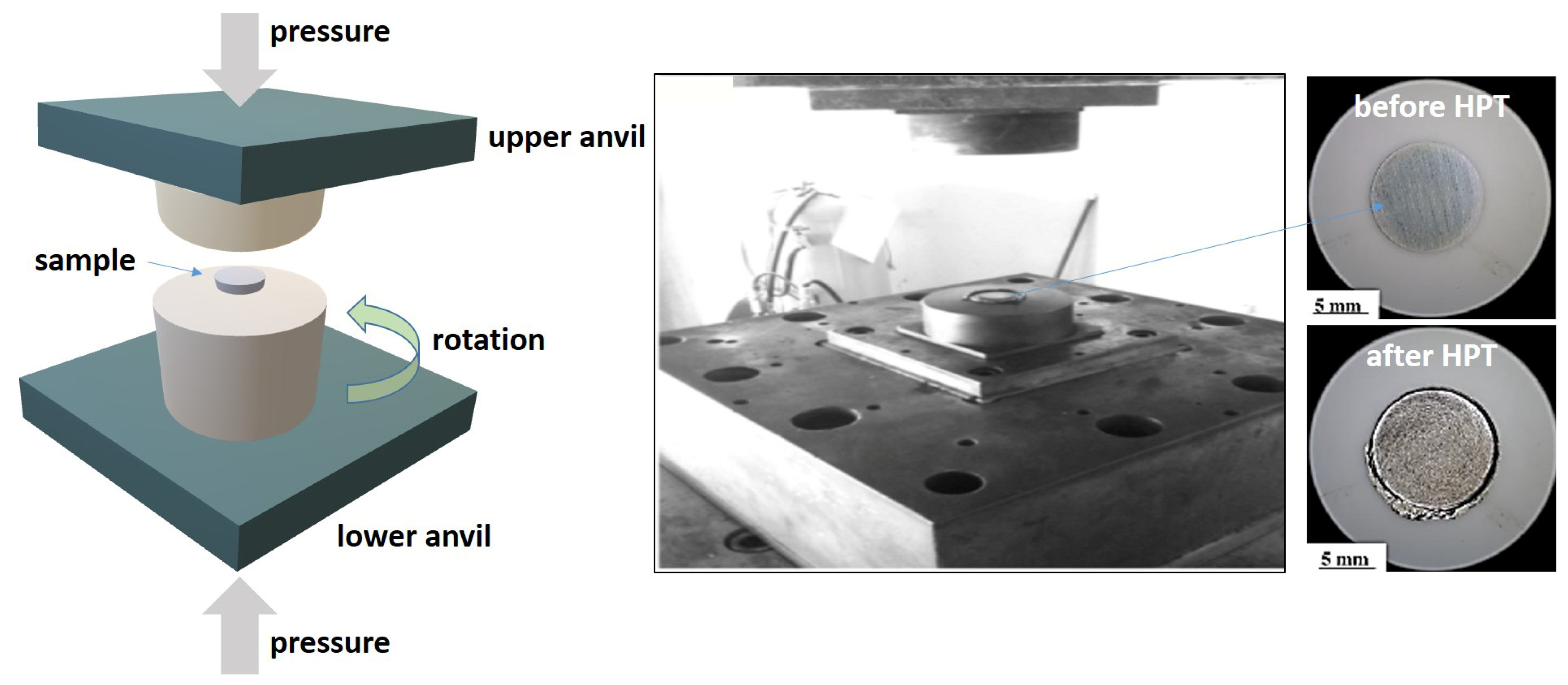
Figure 1. Schematic drawing of HPT process and CCM samples before and after HPT.
Crystals 13 00590 g001
Figure 2. XRD patterns of the initial CCMST sample and its counterparts of HPT- and post-heat-treated (CCMHPT0.25-st).
Crystals 13 00590 g002
Figure 3. TEM bright-field images (top) with diffraction patterns (bottom) of the CCMST sample and its counterparts. The initial CCMST sample and post-heat-treated (CCMHPT0.25-st) show spot-type diffraction patterns, while HPT samples exhibit Debby ring diffraction patterns.
Crystals 13 00590 g003
Figure 4. Potentiodynamic scanning (PDS) curves of the CCM samples in PBS at body temperature.
Crystals 13 00590 g004
Figure 5. The surface morphology of the CCM samples after PDS tests.
Crystals 13 00590 g005
Figure 6. The cored surfaces of the samples at the extensive stage of polarization.
Crystals 13 00590 g006
Figure 7. (a) Nyquist and (b) Bode diagrams of experimental data and fitted curves for CoCrMo samples.
Crystals 13 00590 g007
Figure 8. Electrical equivalent circuit (EEC) model for fitting experimental data of CoCrMo samples.
Crystals 13 00590 g008
Figure 9. Evolution of OCP and Icorr before, during, and after sliding, together with the evolution of COF during sliding for CCM samples.
Crystals 13 00590 g009
Figure 10. Analysis of the worn surfaces: (a) representative wear track profiles, (b) total wear volume loss, and (c) OM images of wear tracks for each sample.
Crystals 13 00590 g010aCrystals 13 00590 g010b
Table 1. Chemical composition of CoCrMo alloy (wt.%).
CoCrMoNiMnSiCNFe
bal.27.75.87<0.010.580.500.0450.14<0.1
Table 2. Open-circuit potential (Eocp), corrosion potential (Ecorr), passivation current density (ipass), and breakdown potential (Ebd) values obtained from PDS curves of the CCM samples.
IDEocp (V)Ecorr (V)ipass (μA·cm−2)Ebd (V)
CCMST−0.23 (±0.10)−0.25 (±0.11)1.57 (±0.48)0.43 (±0.01)
CCMHPT0.25−0.28 (±0.06)−0.31 (±0.07)1.87 (±0.28)0.42 (±0.02)
CCMHPT0.25-st−0.29 (±0.05)−0.32 (±0.06)1.64 (±0.06)0.42 (±0.01)
CCMHPT5−0.30 (±0.05)−0.33 (±0.07)1.41 (±0.21)0.42 (±0.00)
Table 3. Equivalent circuit parameters obtained from EIS data for CoCrMo samples.
IDRox (MΩ·cm2)Cox (µF·cm−2)
CCMST1.37 (±0.65)3.19 (±0.98)
CCMHPT0.251.78 (±1.22)3.36 (±1.51)
CCMHPT0.25-st1.97 (±1.06)2.48 (±0.81)
CCMHPT52.10 (±1.35)2.60 (±0.20)
Disclaimer/Publisher’s Note: The statements, opinions and data contained in all publications are solely those of the individual author(s) and contributor(s) and not of MDPI and/or the editor(s). MDPI and/or the editor(s) disclaim responsibility for any injury to people or property resulting from any ideas, methods, instructions or products referred to in the content.