Article

Corrosion Performance of Commercial Alloys and Refractory Metals in Conditions for Electrorefining of Spent Nuclear Fuels

1
China Institute of Atomic Energy, Beijing 102413, China
2
Shaanxi Key Laboratory of Advanced Nuclear Energy and Technology, Shaanxi Engineering Research Center of Advanced Nuclear Energy, School of Nuclear Science and Technology, Xi’an Jiaotong University, Xi’an 710049, China
*
Author to whom correspondence should be addressed.
Crystals 2023, 13(5), 817; https://doi.org/10.3390/cryst13050817
Submission received: 25 March 2023 / Revised: 9 May 2023 / Accepted: 11 May 2023 / Published: 14 May 2023
(This article belongs to the Special Issue Emerging Nuclear Materials)

Abstract

:
Molten LiCl-KCl salt and liquid cadmium are proposed as the electrolyte and the reactive cathode for the electrorefining of spent nuclear fuels, but they can be corrosive to the structural alloys. The down-selection of existing materials through corrosion testing is necessary to ensure the longevity of the electrorefiner vessel and electrode assemblies. Haynes C276, Inconel 600, AISI 316L stainless steel, and 42CrMo low-alloy steel were exposed to a LiCl-KCl melt at 500 °C for 500 h in an argon atmosphere. All alloys suffered from dissolution attacks with the presence of oxide islands or a porous oxide layer on the surface. AISI 316L, T91 steel, and tungsten specimens were submitted to corrosion tests in liquid cadmium at 500 °C for 120 h. The corrosion of AISI 316L and T91 stainless steel was predominated by chemical oxidation, with the additional occurrence of severe Ni dealloying and Cd penetration on AISI 316L. Destabilization of the Cr oxide layer by cadmium was discovered, resulting in the formation of CdCrO4. Tungsten only suffered from a dissolution attack at a rate of 0.50 mm/a.

1. Introduction

Pyroprocessing is an alternative approach to the conventional hydrometallurgy process for the reprocessing of spent nuclear fuels (SNFs), which is more compatible with the fast reactor fuel cycle. The key step of the pyroprocessing is the electrorefining of uranium in LiCl-KCl molten salt. In this step, uranium and transuranic elements in the SNF are dissolved in the molten salt and selectively recovered on the solid cathode and liquid cadmium cathode, respectively [1].
However, the structural alloys used for the construction of the electrorefiner vessel and electrode assemblies may suffer corrosion attack. In general, molten chloride salts can cause the corrosion of alloys by the active dissolution of the alloy constituents, selective attack, pitting, intergranular corrosion, and oxidation [2]. It is known that the traditional corrosion-resistant alloys rely on the formation of passive oxide film on the alloy surface in aqueous solutions. However, the formation of such protective oxide film is typically unfavorable in molten chloride media. In fact, the electrorefining of metallic SNFs is performed in an inert argon atmosphere with minimized oxygen and water contaminants. The electrorefining works in a batch processing mode. For each batch treatment, the lid of the electrorefiner is uncapped to load the SNF rods into the anode basket and to collect the actinide products deposited on the cathodes. Obviously, the cover gas in the electrorefiner is exposed to the atmosphere of the hot cell that hosts the electrorefiner. The hot cell is operated under slightly negative pressure to prevent the release of radioactive gaseous fission products to adjacent areas. This also increases the risk of air ingress from the adjacent areas. Typically, the levels of moisture and oxygen impurities in the argon atmosphere range from less than 1 ppm to tens of ppm depending on the scale of the reprocessing facility. With reference to the pilot-scale (100 T/year) pyroprocessing facility developed by Argonne National Laboratory and Merrick & Company, the fuel processing hot cell is filled with dry argon inert atmosphere that is maintained through a gas ventilation system [3,4]. In this pilot-scale design, the required impurity levels in the argon atmosphere are within O2 = 60 ± 40 ppm and H2O = 60 ± 40 ppm [4]. Such high oxygen partial pressure is considerably higher than the dissociation pressures of oxides, e.g., the values of Cr2O3, Fe3O4, and NiO at 500 °C are in the orders of 10−42, 10−30, and 10−22 atm, respectively [5]. This means that the formation of Cr2O3, Fe3O4, and NiO on the structural alloys is thermodynamically favorable. However, the stability of the oxide layer is challenged in molten chloride media. The fast dissolution of Cr2O3 layers in the form of hexavalent chromium ions in molten chloride and chloride/sulfate salt deposits has been previously reported [6,7]. Furthermore, the moisture can react with chlorine ions in the salt to form O2− ions according to Reaction (1). Then, the O2− impurity can react with LiCl to form soluble ternary products such as LiCrO2 or LiNiO2, which is known as the basic fluxing dissolution of the oxide layer [8,9].
H 2 O ( g ) + 2 Cl     O 2 + 2 HCl ( g )
Thanks to the recent development of concentrated solar power (CSP) technology, the corrosion behaviors of many commercial alloys in molten chloride salts, including NaCl-LiCl and MgCl2-NaCl-LiCl, have been extensively studied [10,11]. For example, Ding et al. [12] observed the selective and intergranular corrosion of SS 310, Incoloy 800 H, Hastelloy C-276 after exposure in molten MgCl2-NaCl-LiCl under an inert atmosphere at 700 °C for 500 h. They found the corrosion was driven by the moisture impurities in the argon gas, resulting in the formation of oxide corrosion products (e.g., MgCr2O4 or MgSiO3) on the alloy surface and in the corroded pores. So far, the corrosion studies in molten LiCl-KCl salt are very limited. Several studies have focused on the effect of dissolved actinide (e.g., UCl3) and fission products (e.g., EuCl3, NdCl3, CeCl3) on the dissolution kinetics of alloys in molten LiCl-KCl salts [13,14,15]. Shankar et al. [16,17,18] compared the corrosion resistance of several existing alloys in molten LiCl-KCl salts under argon and air atmospheres. They deduced that corrosion rate only became pronounced in a reactive atmosphere. Under the argon atmosphere, the weight changes of 2.25Cr-1Mo, 9Cr-1 Mo, Ni-based alloys (alloy 600, 625, and 690) ranged from −0.18 to +1.25 wt%. Preferential leaching of Cr from the alloy surface and the formation of Cr-rich corrosion products appeared to be a common phenomenon for all alloys tested. Using laser Raman spectroscopy, Rao et al. [19] confirmed the formation of lithium chromite (LiCrO2) and Fe and Cr oxides along with spinel peaks on SS 410, alloy 600, and 9Cr-1Mo steel in LiCl-KCl salts. Our previous study indicated that without the presence of aggressive EuCl3 in LiCl-KCl salt, the corrosion of Haynes C276, Inconel 600, Incoloy 800, 316L stainless steel in molten LiCl-KCl seemed insignificant in blank LiCl-KCl salt after 24 h of immersion tests [20]. The corrosion rates determined from the polarization curves of Haynes C276, Inconel 600, Incoloy 800, and 316L SS were 0.28 mm/a, 0.10 mm/a, 0.06 mm/a, and 0.14 mm/a, respectively [20]. However, to ensure adequate vessel integrity through the entire design life of more than 40 years, there is a need to further evaluate the corrosion performance of these alloys in molten salt through long-term corrosion testing.
Moreover, the electrorefiner vessel, cathode assemblies, and agitators are also in contact with the liquid cadmium. The solubility of alloying elements such as Ni is more than 10 at% in liquid cadmium at 500 °C [21]. This is much higher than their solubilities in liquid lead and lead-bismuth eutectic [22]. In fact, as a promising candidate coolant for future nuclear reactors, the corrosion dissolution and the resulting embrittlement problems of structure alloys in liquid lead and lead-bismuth eutectic are well known and have been extensively studied in the past two decades [23,24]. To the authors’ knowledge, no study has been undertaken on the corrosion behaviors of alloys in liquid cadmium. The stability of oxide layer in the liquid cadmium condition is also unknown, which is investigated in present study.
In this work, corrosion of Haynes C276, Inconel 600, AISI 316L stainless steel, and 42CrMo low-alloy steel were carried out in a LiCl-KCl melt under an argon atmosphere at 500 °C for 500 h. AISI 316L, T91 steel, and refractory tungsten were submitted to corrosion tests in liquid cadmium at 500 °C for 120 h. After exposure, the corrosion behaviors of these materials were evaluated by the scanning electron microscope (SEM) and X-ray diffraction (XRD) characterization methods. The corrosion behaviors of alloys in cadmium were also investigated for the first time. The fundamental data and the related corrosion characteristic discovered in this work will benefit the down-selection of existing alloys that can be applied as the structural materials for the electrorefiner.

2. Materials and Methods

The nominal chemical compositions of the materials tested in the present study are shown in Table 1. Haynes C276, Inconel 600, AISI 316L, T91, 42CrMo steel, and tungsten (99.99 purity) were cut into dimensions of 15 mm × 5 mm × 2 mm for corrosion testing. All specimens were ground to 1500 grit SiC papers, then polished with a 0.3 µm alumina polishing agent. Prior to testing, alloy specimens were cleaned with acetone, deionized water, and ethanol and then dried.
The electrorefining of spent nuclear fuels was performed under high-purity argon atmosphere with minimized oxygen and water contaminants. A gas ventilation system maintained the argon atmosphere in the hot cell that hosted the electrorefiner by recirculating argon gas through the purification systems. In this work, all salt preparations were conducted in an argon-filled glove box (MIKROUNA Universal 2440) to minimize the moisture and oxygen contamination of the chloride salt. In the glove box, the atmosphere was automatically refreshed by the argon gas purification system, and the concentrations of moisture and oxygen in the argon atmosphere were controlled to less than 1 ppm each. The corrosion tests were carried out in a high-temperature autoclave installed on the bottom of the glove box. The schematic diagram of corrosion test setup is shown in Figure 1. The cover gas of the autoclave was connected to the atmosphere of the glove box. Here, the glove box was used to simulate the hot cell equipped with the gas ventilation system, while the cover gas in the autoclave was similar to that of the electrorefiner. Therefore, the autoclave was not a closed system where the moisture and oxygen would soon be exhausted from the corrosion reactions. In this work, the cover gas contained very low concentrations of moisture and oxygen, but they were replenished continuously through the glove box system, which is similar to the electrorefiner conditions.
LiCl (99.9% purity) and KCl (99.99% purity) salts procured from Aladdin were weighted to prepare the LiCl-KCl eutectic salt using an analytical balance (Mettler, 10−4 g accuracy). Prior to corrosion testing, the salt mixture was dehydrated at 200 °C in an alumina crucible for 1 h. Then, the salt was melted at 500 °C, which is the typical operating temperature for the electrorefining of the metallic SNFs. Alloy specimens were fully immersed in the molten salt and tested for 500 h at 500 °C. After the corrosion test, alloy specimens were naturally cooled to room temperature, and the residual salt on the coupon surface was cleaned with deionized water and ethanol. For the liquid cadmium corrosion test, cadmium granules (99.99% purity) were melted in an alumina crucible in the argon filled glove box. Using the corrosion setup in Figure 1, alloy specimens were exposed to the liquid cadmium for 120 h at 500 °C.
After exposure, a Zeiss GeminiSEM 500 scanning electron microscope equipped with an Oxford Ultim Max 50 energy-dispersive spectroscopy (EDS) system was employed to characterize the corrosion morphologies and chemical compositions of the corrosion products.

3. Results

3.1. Corrosion in Molten LiCl-KCl Eutectic

Moisture is the most common contaminant in the consideration of the hydrophilic nature of chloride salt, which is also perhaps the most deleterious impurity in molten chloride salt. The accelerated corrosion of nickel and iron by the presence of moisture in the molten chloride media has been demonstrated in several studies [25,26,27]. The moisture contamination also produces impurities of O2− ions through Reaction (1), which could alter the forms of the corrosion products. The concentrations of O2− ions can be referred to the salt basicity as defined by pO 2 = log   a O 2 . Metals can be corroded as soluble chlorides and/or solid oxides depending on the electrode potential and the salt basicity. The thermodynamical stability domains of corrosion products can be illustrated by the E-pO2− diagram. The calculated E-pO2− diagrams for nickel, iron, chromium, and molybdenum in molten LiCl-KCl salt at 500 °C are given in Figure 2. The activities of MCln (M represents Ni, Fe, Cr, and Mo) in the salt were assumed to be 10−6 for the equilibrium calculations. The electrode potential was plotted versus Ag/AgCl by considering the correlation between the standard potential of Ag/AgCl with standard Cl2/Cl potential in LiCl-KCl eutectic [28]. At sufficiently low concentrations of oxide ions impurities, metals are submitted to dissolution through chlorination reactions. Alloying elements that have high negative Gibb’s free energy of chloride formation are more prone to active dissolution, i.e., E Mo / MoCl 2 > E Ni / NiCl 2 > E Fe / FeCl 2 > E Cr / CrCl 2 . With the increase of the impurities of O2− ions in the melt, formation of oxides of metals becomes thermodynamically favorable. As shown in Figure 1, oxides of Cr and Mo can be formed at much lower concentrations of O2− ions compared to Ni and Fe oxides. More complicated, the oxide layer formed on the metal surface can also be dissolved by the basic fluxing mechanism in which case the oxide layer reacts with the O2− and/or O2 impurities to form soluble ternary products such as LiCrO2 or LiNiO2 [8,9]. The corrosion performance of alloys also largely depends on their chemical composition and microstructural characteristics (e.g., grain size, grain boundary, and the secondary precipitates). Therefore, there is a need to evaluate the corrosion performance of various alloys through corrosion testing.

3.1.1. 42CrMo Steel

The 42CrMo steel is a typical low-alloy, medium-carbon, high-strength steel, containing about 1 wt% Cr and 0.2 wt% Mo. Figure 3 shows the corrosion morphology of 42CrMo steel after 500 h of immersion in the molten LiCl-KCl salt at 500 °C. The SEM surface micrograph in Figure 3a exhibits a porous microstructure. The examination of the cross section revealed a severely uneven steel surface with localized pore attacks up to 10.2 µm depth (see Figure 3b). The contrast of the backscattered electron image indicated barely any oxide product on the steel surface. However, the EDS elemental mapping manifested some oxygen enrichment at the steel surface, indicating the possible formation of an oxide layer. The EDS point analysis found some scattered iron oxide islands on the steel surface, as evidenced by the composition of point 2 in Figure 3b. The two pores in Figure 3b were seemingly isolated from the steel surface, but they could be a 2-D side view of sideway pores that had an undercutting or subsurface shapes. The EDS quantitative analysis of point 1 in the deep pore resulted in a composition of 60.41 at% Fe, 8.61 at% Cr, and 30.99 at% O. The EDS analysis of point 4 also indicates the formation of iron-chromium oxides inside the isolated pore. Therefore, it was proved that these pores were formed by the corrosion process, and the corrosion products were iron and chromium oxides. They should have narrow openings, which were not observed in the 2D cross-section in Figure 2b. Compared to the 1 wt% of Cr in the steel matrix, obvious chromium enrichment of the corrosion products inside the pores was evidenced. In comparison, no such Cr enrichment was observed from the oxide islands on the steel surface, as indicated by the EDS analysis of point 2. This could be attributed to the higher thermodynamic stability of chromium oxides (e.g., Cr2O3) compared to iron oxides (e.g., Fe3O4), as indicated by Figure 2. The concentration of O2− ions in the pores might have been lower than the bulk solution due to the difficulty of inward diffusion of O2− ions. At low O2− ions concentrations, the formation of iron oxides became less favorable than chromium oxides.

3.1.2. AISI 316L

AISI 316L stainless steel is an austenitic chromium-nickel stainless steel that contains 16–18 wt% Cr, 10–14 wt% Ni, and 2–3 wt% Mo. Figure 4 shows the SEM micrographs and EDS analysis results of AISI 316L exposed for 500 h to the molten LiCl-KCl salt at 500 °C. AISI 316L exhibited a less uneven surface morphology compared to 42CrMo steel. Pieces of residual oxide scales can still be observed on the steel surface. The cross-sectional SEM image of AISI 316L showed a relatively uniform near-surface corroded layer with a thickness of 9.4 µm. In our previous study, the corrosion rate of AISI 316L determined from the polarization curve in LiCl-KCl salt was 0.14 mm/a [20]. This corresponds to a corrosion depth of 8.0 µm. As the polarization curve was measured after about 1 h of immersion of 316L sample in the molten salt, it can be deduced that the corrosion rate remained unchanged during 500 h of immersion. The dissolution feature was similar to 42CrMo steel, but more oxide islands were visually distributed in the pores of corroded near-surface region. The oxide islands were mainly composed of chromium oxides, as evidenced by the EDS quantitative analysis of points 1 and 2 in Figure 4b. Again, this suggests that chromium oxides are more stable in molten chloride media than that of iron oxides. The residual steel matrix adjacent to the oxide islands in the near-surface corroded region contained less Fe and more Ni compared to the bulk steel matrix, as displayed by the EDS analysis results of points 3 and 4. This indicates that iron is less resistant to dissolution than that of Ni, which can be attributed to the more negative chlorination potential of iron. Feng and Melendres [29] reported equilibrium potentials of −2.004 V versus Li+/Li for Ni(II)/Ni and 1.590 V versus Li+/Li for Fe(II)/Fe electrode reactions in molten LiCl-KCl eutectic at 450 °C. Compared to the localized pore attack observed on 42CrMo steel, AISI 316L exhibited a porous corroded surface structure through the entire sample surface. However, severe intergranular attacks were observed on AISI 316L. As shown in Figure 4a, massive, connected voids were concentrated at the grain boundaries. This might be attributed to the sensitization effect of stainless steel, which is widely known to affect the intergranular corrosion behavior in aqueous solution. When austenitic stainless steel is heated in the sensitization temperature range between 450 °C and 850 °C for a long time, chromium carbides can precipitate on the grain boundaries, leading to the depletion of Cr solute in the adjacent region. Thus, less chromium oxide products will be formed on the grain boundary surface, which may make the grain boundary more susceptible to dissolution compared to the grain itself. The sensitization effect on the corrosion in molten chloride media has been previously reported by Polovov et al. [30], who studied the corrosion of austenitic stainless steel in molten NaCl-KCl salt. The resistance to intergranular corrosion was improved in the order of AISI 316L (<0.03C, 2.2–2.8Mo, in wt%) > AISI 316Ti (<0.1C, 0.5–0.7Ti, 2.0–3.0Mo, in wt%) > AISI 321 (<0.12C, 0.5–0.8Ti, in wt%), due to the decrease of the carbon content or increase of the content of strong carbide-forming elements.

3.1.3. Inconel 600

Inconel 600 is a nickel-chromium alloy with good oxidation resistance at higher temperatures. The high nickel content of the alloy enables it to retain considerable resistance to active dissolution under reducing conditions, while the addition of 14–17 wt% chromium content provides alloy resistance to various oxidizing environments by forming passive oxide film. Figure 5 shows the representative SEM corrosion morphology of Inconel 600 specimen after 500 h of immersion in the molten LiCl-KCl salt. In general, there were many flocculent structures of corrosion products distributed in clumps on the surface. There were also some micropores in local areas. As indicated by the cross-sectional SEM image in Figure 5b, the entire surface was covered by an oxide layer with thickness ranging from 3 to 6 µm. The flocculent corrosion products were accumulated on the top of this oxide layer. Both the oxide layer and flocculent corrosion products were composed of chromium oxides with a small iron content and nickel elements. Compared to the 72.79 at% Ni and 9.01 at% Fe in the alloy matrix (see EDS analysis of point 4 in Figure 5b), nickel and iron content in the oxide layer were obviously depleted. This indicates that even the relatively more electropositive nickel was dissolved in the molten chloride media through the chlorination reaction, i.e., Ni/NiCl2. In comparison, chromium was preferentially oxidized rather than chlorinated, likely due to the stability of Cr2O3 at lower concentrations of O2− (see Figure 2). Moreover, fluctuation of the alloy surface and some cavities below the oxide layer can be observed from Figure 5b. This might be a precursor that localized attack that may occur when the alloy is exposed to the salt for longer time duration. In our previous study, the corrosion rate of Inconel 600 determined from the polarization curve was 0.10 mm/a [20]. This corresponds to a corrosion depth of 6 µm, which is quite consistent with the oxide layer thickness observed in Figure 5b. Obviously, compared to results from the polarization curve measured at about 1 h of immersion of the Inconel 600 sample, the decrease of the corrosion rate after 500 h of immersion was very limited. This indicates that the formed oxide layer was not protective.

3.1.4. Haynes C276

Haynes C276 is a nickel-based superalloy with more than 50 wt% nickel, 15–17 wt% molybdenum, and 14.5–16.5 wt% chromium. Haynes C276 exhibited a unique corrosion morphology compared to AISI 316L and Inconel 600, as shown in Figure 6. The SEM surface image demonstrated massive precipitates on the alloy surface. Examination of the cross section revealed a uniform oxide layer underneath these precipitates. Visually, there were still some light-contrast alloy matrices that remained in the oxide layer. The EDS elemental mapping revealed that the oxide layer was enriched in Cr and O with presence of some Ni. The EDS quantitative analysis of points 2 and 3 exhibited an atomic ratio of Cr/O that was very close to Cr2O3. The detected 10–13 at% of Ni in the thin oxide layer was likely associated with the residual nickel matrix. The top precipitates were composed of more than 80 at% Ni and about 12–13 at% Fe. No molybdenum was detected either in the top precipitates or in the thin oxide layer. This suggests that Mo in the near-surface corroded region must be readily dissolved in the molten salt. However, Mo is more prone to chlorination than that of Ni and Fe. Thus, the depletion of Mo in the nickel matrix suggests that Mo was oxidized to volatile Mo oxides. In fact, the formation of molybdenum oxides is thermodynamically favorable in salt with concentrations of O2− ions as low as that for the formation of chromium oxides (see Figure 2). Among MoO2 and MoO3, MoO3 is more volatile at evaluated temperatures. The melting temperature of MoO3 is 795 °C, indicating a relatively high vapor pressure. Thus, it is speculated that Mo in the Haynes C276 was corroded through the formation of volatile MoO3. As Cr was also preferentially oxidized as Cr2O3, remaining Ni and Fe were alloyed to form Ni-Fe precipitates in the near-surface corroded region. This suggests that the significant amount of Mo addition in Haynes C276 might be detrimental, as the evaporation of volatile Mo oxides could break down the chromium oxide layer and increase the dissolution rate of the alloy matrix underneath. Such effects have been previously reported by Shankar et al. [17], who found that the corrosion rate of Inconel 625 (Ni-18Cr-4Fe-11Mo) was remarkably higher than Inconel 600 (Ni-17Cr-10Fe-1Mn) in molten LiCl-KCl eutectic due to the presence of Mo in Inconel 625.
The corrosion rate of Haynes C276 determined from the polarization curve after 1 h of immersion in LiCl-KCl salt was 0.28 mm/a [20]. This corresponds to a corrosion depth of 16.0 µm. This agrees with the overall thickness of the oxide layer and Ni-Fe precipitate layer in Figure 6b. Therefore, these results suggest that the change of the corrosion rate was limited during the 500 h of immersion, and the alloy suffered from active dissolution.

3.2. Corrosion in Liquid Cadmium
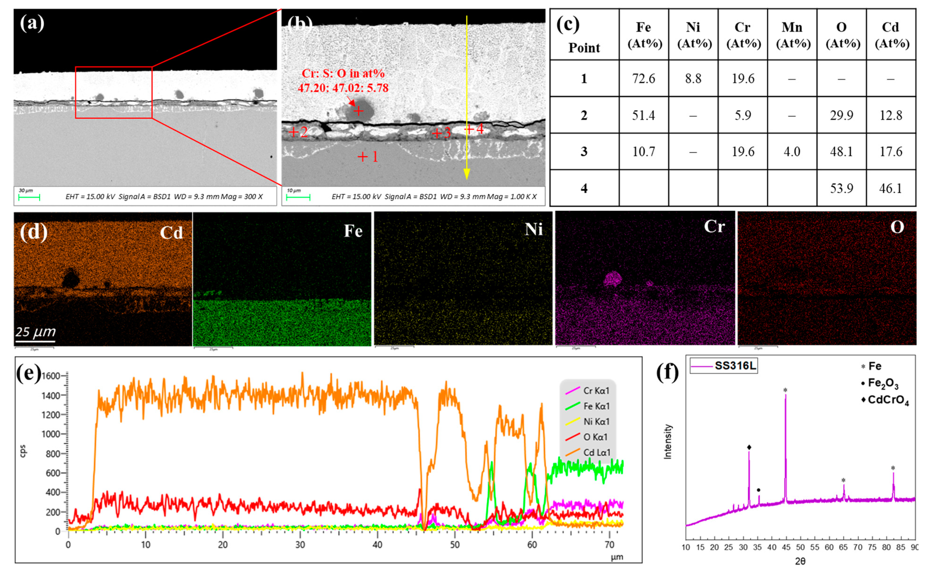
In liquid metals, corrosion of the metal structure can proceed as a physical dissolution or chemical oxidation process, depending on the solubilities of alloying elements and the oxygen partial pressure in the system [22]. In low-oxygen partial pressure conditions, the physical dissolution is predominated, which is driven by the solubility of alloying elements in the liquid metal. For alloying elements of traditional corrosion resistance alloys, nickel is most soluble in liquid cadmium. According to the Ni-Cd phase diagram, the solubility of Ni in liquid Cd at 500 °C is slightly more than 10 at% [21]. There are two Ni-Cd intermediate phases, i.e., Cd5Ni and CdNi, which can be formed at temperatures below 495 °C and 690 °C, respectively. Thus, when Ni is saturated in Cd at 500 °C, CdNi will be precipitated out. In comparison, Fe and Cr are almost insoluble in liquid Cd at 500 °C. Using a radiotracer technique, Chasanov et al. [31] found solubilities of Fe in liquid Cd of 2.4 × 10⁻⁴ at% at 421 °C and 4.4 × 10⁻¹ at% at 647 °C, respectively. The solubilities of Cr in liquid Cd are 6.2 × 10⁻⁴ at% at 450 °C and 37.3 × 10⁻¹ at% at 650 °C [31]. This indicates that nickel-based alloys and nickel bearing steels may suffer the selective dissolution of nickel in the near-surface region. The dissolution may be accompanied with the penetration of cadmium into the alloy matrix. This could result in alloy embrittlement, which is widely known as liquid metal embrittlement. When the oxygen partial pressure becomes higher than the saturated oxygen pressure for oxides, liquid metal corrosion may alter the chemical oxidation mechanism in which the oxidation kinetics are dependent on the oxygen partial pressure, temperature, and mass transport in the alloy and liquid metal phases. The saturated oxygen pressures for Cr2O3, Fe3O4, NiO, and CdO are in the orders of 10−42, 10−29, 10−23, and 10−25 atm at 500 °C, respectively. In the electrorefining conditions, the concentration of oxygen impurities in the argon cover gas is typically controlled in the range from several to tens of ppm. Thus, formations of Cr2O3, Fe3O4, NiO, and CdO are all thermodynamically possible. Therefore, it is necessary to investigate the corrosion mechanisms of structural materials in liquid cadmium.

3.2.1. AISI 316L

Figure 7 shows the cross-sectional SEM images and the corresponding EDS and XRD analysis results of AISI 316L stainless steel after 120 h of exposure in liquid cadmium at 500 °C. The bright contrast in the backscattered electron image (Figure 7a,b) is the heavy metal cadmium that adhered on the steel surface. At the interface of 316L steel and cadmium, a uniform oxide layer with a thickness of about 6–9 µm was formed. Obviously, the protectiveness of this oxide layer was limited as the bright cadmium phase was embedded into the dark oxide layer, indicating the penetration of cadmium. Even for the dark oxide phase, the EDS quantitative analysis of point 2 and point 3 exhibited 12–18 at% of Cd. The XRD analysis of the corroded AISI 316L exhibited diffraction patterns associated with Fe2O3 and CdCrO4 compounds (see Figure 7e). The phase equilibria for the system of CdO-Cr2O3-O2 was previously determined by Muller et al. [32]. In their phase diagrams, the stability domains for oxides, including α-CdCrO4, β-CdCrO4, CdCr2O4, and Cd2CrO5 as the functions of temperature and oxygen pressure, were well defined. At our experimental conditions, i.e., 500 °C and very low oxygen pressure, only Cr2O3 and α-CdCrO4 were thermodynamically stable. This is very consistent with our results in which CdCrO4 corrosion product was identified from the XRD analysis. The Cr2O3 was not identified from the XRD pattern, likely due to the amorphous feature of Cr2O3 products. In comparison, the oxide layers formed on AISI 316L in liquid lead bismuth eutectic under argon atmosphere typically manifest a dual-layer structure [33]. The outer oxide layer is mainly magnetite (Fe3O3) with the formation of plumboferrite (e.g., PbFe12O19 or PbFe6O10) sometimes at the outmost part. The inner oxide layer is composed of spinel Fe(Fe1−x, Crx)2O4 and non-oxidized Ni phase. Such a double oxide layer can act as a barrier to prevent the penetration of Pb and Bi into the steel matrix. However, in liquid cadmium conditions, Cd can permeate through the oxide layer by forming CdCrO4. As shown in Figure 7b, the penetration of Cd into the steel matrix up to a depth of about 11 µm was also observed underneath the oxide layer. This is very similar to the typical morphology of bismuth penetration into the austenitic stainless steels in liquid lead bismuth eutectic, which is caused by depletion of the high solubility of Ni in the near-surface region [34,35]. The selective depletion of Ni causes the transition from the austenitic phase to the ferrite phase in the near-surface region as Ni is a strong austenitic stabilization element. As a reminder, this phenomenon only occurs in liquid lead bismuth eutectic with depleted oxygen concentrations under a Ar-H2 or Ar-H2-H2O atmosphere. Under such conditions, there are no oxides, or only a porous oxide layer is formed on the steel surface, which allows the penetration of Pb and Bi into the steel matrix. However, Figure 7b shows that Cd can penetrate into the AISI 316L steel matrix, even under an argon atmosphere where oxygen is typically saturated in liquid Cd. This could be attributed to the formation of CdCrO4 in the oxide layer. The depletion of Ni in the Cd penetration zone underneath the oxide layer was also identified from the EDS line scan (see Figure 7d). As we mentioned, the solubility of Ni in liquid Cd at 500 °C is more than 10 at%. Ni was also not detected in the oxide layer because the formation of NiO is also thermodynamically less favorable than that of Cd, Fe, and Cr. Thus, Ni in the steel matrix must be readily dissolved in the liquid cadmium. This will lead to the transition of austenitic phase to ferritic phase as previously acknowledged in the field of liquid lead bismuth corrosion [34,35]. Then, liquid cadmium will penetrate into the Ni depleted region through the voids left by Ni and the grain boundaries of the fragmentized ferritic grains. In addition, sulfur oxide particles were observed outside the oxide layer surface. This indicates that sulfur impurities in the stainless steel were transferred to the liquid cadmium phase, likely through the replacement reactions between Cd or CdO with sulfide inclusions in the stainless steel such as FeS or MnS.

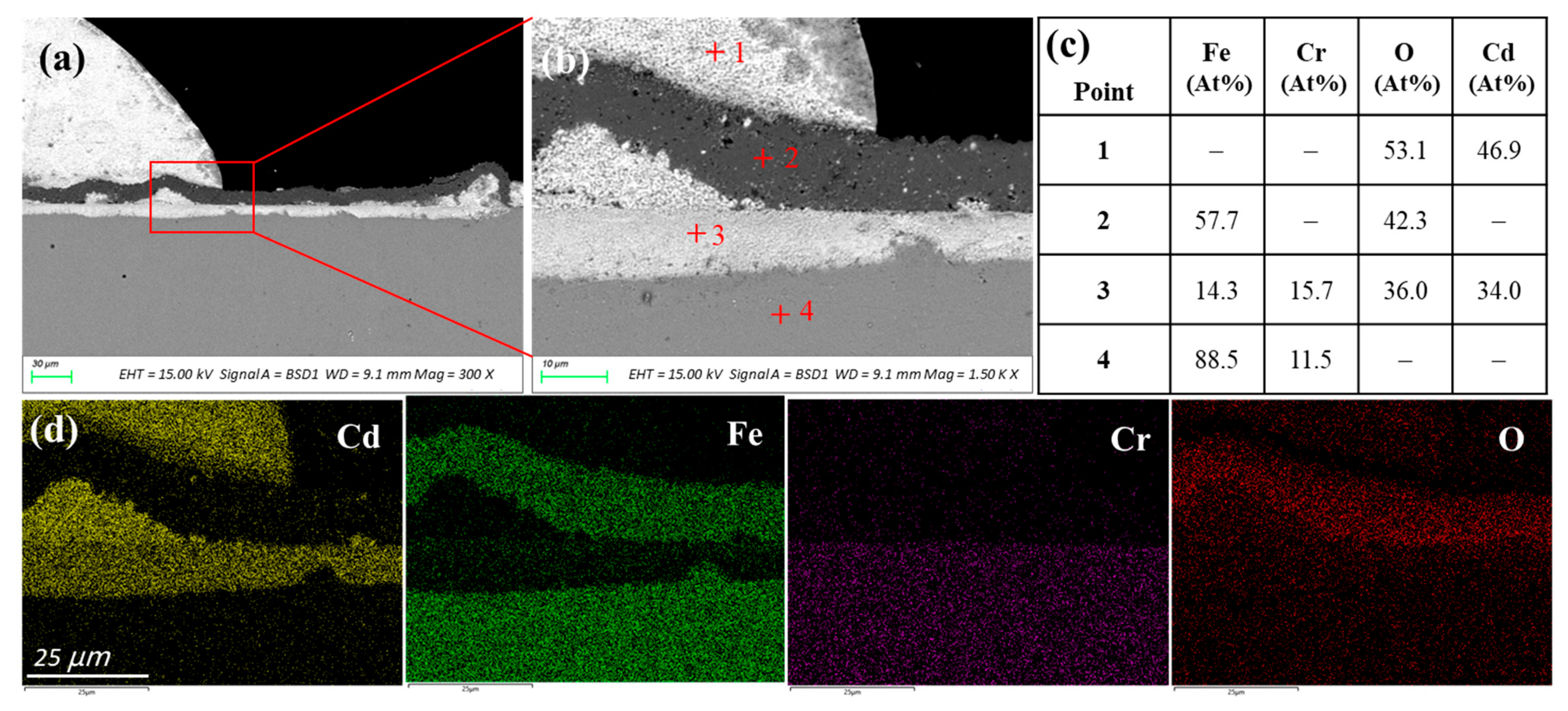
3.2.2. T91 Stainless Steel
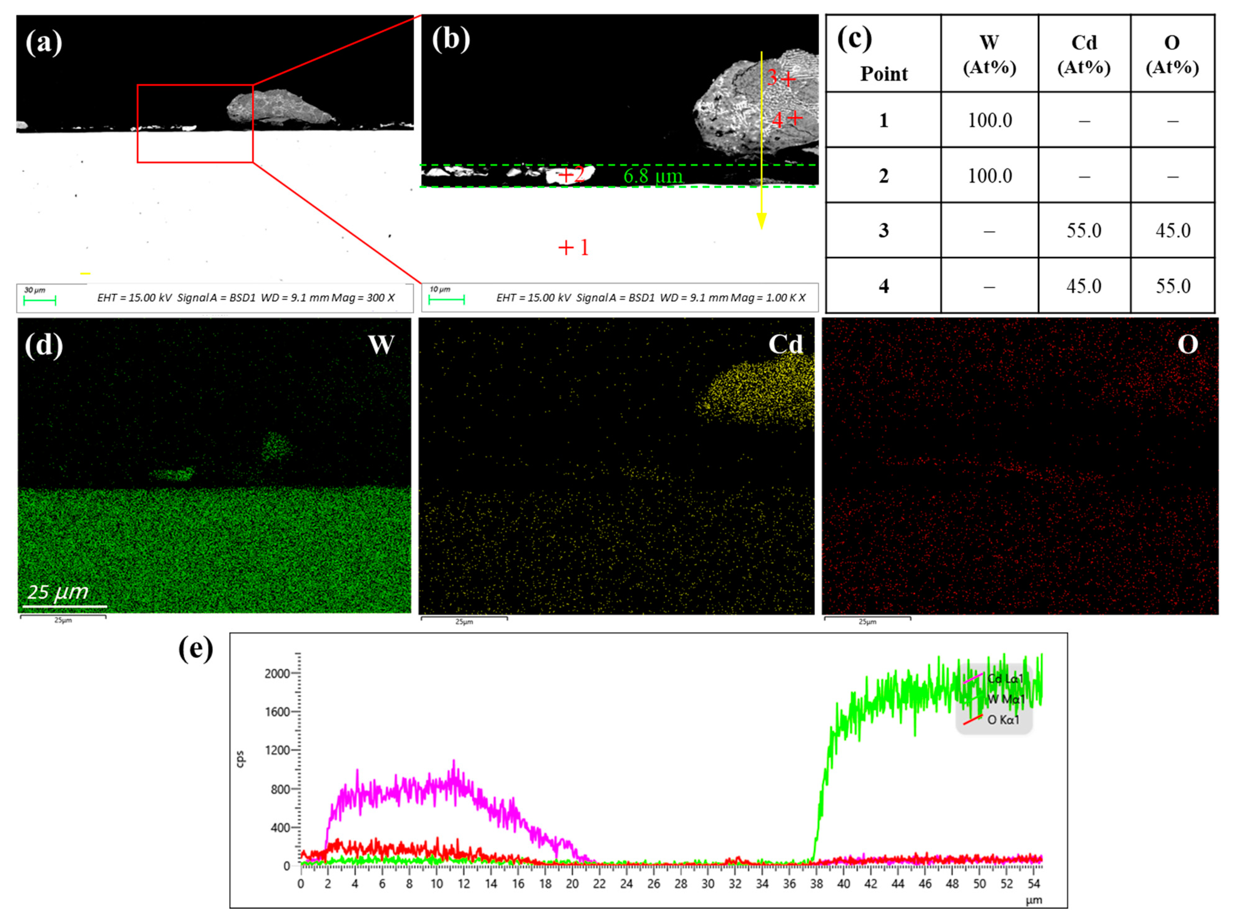
T91 is a martensitic Cr-bearing stainless steel containing about 9 at% Cr and 1 at% Mo. As shown in Figure 8, T91 steel exhibited a bi-layer structure after exposure for 120 h in liquid cadmium. The outer layer with a darker contrast consisted of Fe and O with an atomic ratio of Fe to O that was close to 1. In addition to Fe, Cr, and O, the inner layer was enriched with more than 30 at% Cd, indicating the penetration of Cd. Similar to AISI 316L, the inner oxide layer of T91 steel was also composed of Fe2O3 and CdCrO4. In comparison, the oxide layer structure observed on T91 steel in liquid lead bismuth eutectic typically consists of an outer magnetite (Fe3O4) layer and an inner iron-chromium spinel oxide layer, followed by an inner oxidation zone [23,33]. Compared to the protective inner spinel oxide layer in liquid lead bismuth conditions, the inner oxide layer formed in the liquid cadmium was quite reactive with Cd. It is speculated that Cd can diffuse through the outer iron oxide layer and react with the chromium oxide in the inner layer to form a ternary CdCrO4 compound. Selective dissolution of elements and Cd penetration into the steel matrix were not observed. Therefore, the corrosion of T91 martensitic steel in liquid cadmium was predominated by the chemical oxidation mechanism.

3.2.3. Tungsten

To the authors’ knowledge, neither the solubility data of tungsten in liquid cadmium nor the binary phase diagram of W-Cd system are available in the literature. Jang et al. [36] carried out the Cd distillation test from U-Cd alloy in a tungsten crucible at 500 °C and found the tungsten crucible was very stable against Cd, maintaining a shiny surface. However, the time duration was only 200 min for the Cd distillation test. This study further evaluated the compatibility of tungsten with cadmium at a longer time duration. Figure 9 shows the corrosion morphology of pure tungsten after exposure for 120 h in liquid cadmium at 500 °C. As tungsten is heavier than cadmium, it shows a brighter contrast in the backscattered electron image. The saturated oxygen pressures for tungsten oxides are equivalent with that of iron oxides, e.g., values of WO2 and WO3 at 500 °C are in orders of 10−31 and 10−29 atm. Thermodynamically, this means that the oxidation of tungsten is as favorable as iron. However, Figure 9 manifests no sign of oxidation of tungsten on the metal surface. Any chemical interaction between the tungsten and cadmium is also not observed. Hence, tungsten is quite chemically inert in liquid cadmium under an argon atmosphere. Regarding the physical dissolution, many residual fragments of tungsten were observed on the tungsten surface. Their chemical compositions were validated by the EDS analysis (see point 2 in Figure 9). Depletion of tungsten in the near-surface region was also evidenced from the EDS line scan results in Figure 9d. Thus, it is obvious that the dissolution of tungsten occurred in liquid cadmium. Conservatively, at least 6.8 µm thick tungsten was corroded at a duration of 120 h, corresponding to a dissolution rate of 0.50 mm/a.

4. Conclusions

Herein, 42CrMo steel, AISI 316L, Inconel 600, and Haynes C276 were exposed to molten LiCl-KCl salt for 500 h at 500 °C under an argon atmosphere. All test materials exhibited an active dissolution corrosion mechanism with the formation of oxide products on the surface. Notably, 42CrMo exhibited a localized pore attack with limited iron oxide islands formed on steel surface. AISI 316L steels manifested a porous corroded surface layer with more Cr-rich oxide islands distributed in the pores of the corroded region. More pore attacks occurred on the grain boundaries. Inconel 600 showed a less localized attack, and a uniform oxide layer was formed on the alloy surface. Haynes C276 demonstrated the formation of a Cr-rich oxide layer and Ni-Fe precipitate layer. The significant amount of Mo in the alloy was depleted in the corroded region, which may have formed volatile Mo oxides, resulting in the precipitation of Ni-Fe compounds.
AISI 316L, T91 steel, and refractory tungsten were submitted to corrosion tests in liquid cadmium at 500 °C for 120 h. AISI 316L in liquid cadmium suffered from both the dissolution of Ni and chemical oxidation of Fe and Cr. The dissolution of Ni in AISI 316L resulted in the penetration of Cd into the steel matrix to a depth of 11 µm. The rorrosion of T91 stainless steel was predominated by chemical oxidation. Cd was permeated through the outer iron oxide layer and reacted with the chromium-rich oxide inner layer to form CdCrO4. In comparison, tungsten only suffered from physical dissolution with a rate of about 0.50 mm/a.
To mitigate the corrosion in the electrorefining conditions, the addition of other reactive alloy elements to alter the oxide layer composition might be an option to improve the stability of the oxide layer in molten LiCl-KCl salt and liquid Cd metal. Surface coatings using more inert refractory metals, such as tungsten on the structural alloys, are alternative directions for future work.

Author Contributions

Conceptualization, S.G.; methodology, S.G. and Y.J; formal analysis, S.C.; investigation, S.C., Y.J. and X.D.; writing—original draft preparation, S.G. and Y.J; writing—review and editing, S.G.; supervision, S.G.; funding acquisition, S.G. All authors have read and agreed to the published version of the manuscript.

Funding

This research was funded by Natural Science Basic Research Program of Shaanxi Province, grant number 2022JQ-372.

Data Availability Statement

The data presented in this study are available on request from the corresponding author. The data are not publicly available due to privacy.

Acknowledgments

The authors wish to thank Zijun Ren at Instrument Analysis Center of Xi’an Jiaotong University for his assistance with SEM analysis. Special thanks to Jiong Qian at Jiuli Hi-Tech Metals for providing the Haynes C276, Inconel 600, and AISI 316L alloy bars.

Conflicts of Interest

The authors declare no conflict of interest.

References

  1. Williamson, M.A.; Willit, J.L. Pyroprocessing flowsheets for recycling used nuclear fuel. Nucl. Eng. Technol. 2011, 43, 329–334. [Google Scholar] [CrossRef]
  2. Guo, S.; Zhang, J.; Wu, W.; Zhou, W. Corrosion in the Molten Fluoride and Chloride Salts and Materials Development for Nuclear Applications. Prog. Mater. Sci. 2018, 97, 448–487. [Google Scholar] [CrossRef]
  3. Chang, Y.; Benedict, R.W.; Bucknor, M.D.; Figueroa, J.; Herceg, J.E.; Johnson, T.R. Conceptual Design of a Pilot-Scale Pyroprocessing Facility. Nucl. Technol. 2019, 205, 708–726. [Google Scholar] [CrossRef]
  4. Argonne National Laboratory, Merrick and Company, Conceptual Design of a Pilot-Scale Pyroprocessing Facility. Nucl. Technol. 2018, 205, 708–726.
  5. Kawahara, Y. High temperature corrosion mechanisms and effect of alloying elements for materials used in waste incineration environment. Corros. Sci. 2002, 44, 223–245. [Google Scholar] [CrossRef]
  6. Ishitsuka, T.; Nose, K. Stability of protective oxide films in waste incineration environment-solubility measurement of oxides in molten chlorides. Corros. Sci. 2002, 44, 247–263. [Google Scholar] [CrossRef]
  7. Zahrani, F.M.; Alfantazi, A.M. Hot corrosion of Inconel 625 wrought alloy and weld overlay on carbon steel by gas metal arc welding in 47 PbSO4-23 ZnO-13 Pb3O4-7 PbCl2-5 CdO-5 Fe2O3 molten salt mixture. Corros. Sci. 2021, 183, 109348. [Google Scholar] [CrossRef]
  8. Phillips, W.; Chidambaram, D. Corrosion of stainless steel 316L in molten LiCl-Li2O-Li. J. Nucl. Mater. 2019, 517, 241–253. [Google Scholar] [CrossRef]
  9. Liu, R.Y.; Wang, X.; Zhang, J.S.; Wang, X.M. Corrosion of nickel in molten LiCl–Li2O at 750 °C. J. Nucl. Mater. 2004, 327, 194–201. [Google Scholar] [CrossRef]
  10. Ding, W.; Bonk, A.; Bauer, T. Molten chloride salts for next generation CSP plants: Selection of promising chloride salts & study on corrosion of alloys in molten chloride salts. AIP Conf. Proc. 2019, 2126, 200014. [Google Scholar]
  11. Grégoire, B.; Oskay, C.; Meißner, T.M.; Galetz, M.C. Corrosion mechanisms of ferritic-martensitic P91 steel and Inconel 600 nickel-based alloy in molten chlorides. Part II: NaCl-KCl-MgCl2 ternary system. Sol. Energ. Mat. Sol. 2020, 216, 110675. [Google Scholar] [CrossRef]
  12. Ding, W.; Shi, H.; Xiu, Y.; Bonk, A.; Weisenburger, A.; Jianu, A.; Bauer, T. Hot corrosion behavior of commercial alloys in thermal energy storage material of molten MgCl2/KCl/NaCl under inert atmosphere. Sol. Energ. Mat. Sol. 2018, 184, 22–30. [Google Scholar] [CrossRef]
  13. Nikitina, E.V.; Kazakovtseva, N.A.; Karfidov, E.A. Corrosion of 16Cr12MoWSVNbB (EP-823) Steel in the LiSl-KCl Melt Containing CeCl3, NdCl3 and UCl3. J. Alloys Compd. 2019, 811, 152032. [Google Scholar] [CrossRef]
  14. Karfidov, E.A.; Nikitina, E.V. Corrosion Electrochemical Behavior of Nickel in the LiCl-KCl Melt Containing Lanthanum Trichloride. Russ. Metall. 2019, 8, 820–824. [Google Scholar] [CrossRef]
  15. Guo, S.; Zhuo, W.; Wang, Y.; Zhang, J. Europium Induced Alloy Corrosion and Cracking in Molten Chloride Media for Nuclear Applications. Corros. Sci. 2020, 163, 108279. [Google Scholar] [CrossRef]
  16. Shankar, A.R.; Mathiya, S.; Thyagarajan, K.; Mudali, U.K. Corrosion and Microstructure Correlation in Molten LiCl-KCl Medium. Metall. Mat. Trans. A 2010, 41, 1815–1825. [Google Scholar] [CrossRef]
  17. Shankar, A.R.; Kanagasundar, A.; Mudali, U.K. Corrosion of Nickel-Containing Alloys in Molten LiCl-KCl Medium. Corrosion 2013, 69, 48–57. [Google Scholar] [CrossRef]
  18. Shankar, A.R.; Thyagarajan, K.; Mudali, U.K. Corrosion Behavior of Candidate Materials in Molten LiCl-KCl Salt under Argon Atmosphere. Corrosion 2013, 69, 655–665. [Google Scholar] [CrossRef]
  19. Rao, C.J.; Shankar, A.R.; Ajikumar, P.K.; Kamruddin, M.; Mallika, C.; Mudali, U.K. Corrosion Behavior of Structural Materials in LiCl-KCl Molten Salt by Thermogravimetric Study. Corrosion 2015, 71, 502–509. [Google Scholar] [CrossRef]
  20. Chang, S.; Jia, Y.; Du, X.; Guo, S. Corrosion Behavior of Commercial Alloys in LiCl–KCl Molten Salt Containing EuCl3. Front. Mater. 2022, 9, 958296. [Google Scholar] [CrossRef]
  21. Predel, B. Cd-Ni (Cadmium-Nickel), In Phase Equilibria, Crystallographic and Thermodynamic Data of Binary Alloys · Ca-Cd—Co-Zr; Madelung, O., Ed.; SpringerMaterials: Berlin/Heidelberg, Germany, 1993; pp. 1–3. [Google Scholar]
  22. Zhang, J.; Li, N. Review of the studies on fundamental issues in LBE corrosion. J. Nucl. Mater. 2008, 373, 351–377. [Google Scholar] [CrossRef]
  23. Zhang, J. A review of steel corrosion by liquid lead and lead–bismuth. Corros. Sci. 2009, 51, 1207–1227. [Google Scholar] [CrossRef]
  24. Gong, X.; Short, M.P.; Auger, T.; Charalampopoulou, E.; Lambrinou, K. Environmental degradation of structural materials in liquid lead- and lead-bismuth eutectic-cooled reactors. Prog. Mater. Sci. 2022, 126, 100920. [Google Scholar] [CrossRef]
  25. Hosoya, Y.; Terai, T.; Yoneoka, T.; Tanaka, S. Compatibility of structural materials with molten chloride mixture at high temperature. J. Nucl. Mater. 1997, 248, 348–353. [Google Scholar] [CrossRef]
  26. Colom, F.; Bodalo, A. Corrosion of Iron (ARMCO) in KCl-LiCl Melts. Corros. Sci. 1973, 12, 731–7388. [Google Scholar] [CrossRef]
  27. Nishikata, A.; Numata, H.; Tsuru, T. Electrochemistry of molten salt corrosion. Mater. Sci. Eng. A 1991, 146, 15–31. [Google Scholar] [CrossRef]
  28. Fusselman, S.P.; Roy, J.J.; Grimmett, S.L. Thermodynamic Properties for Rare Earths and Americium in Pyropartitioning Process Solvents. J. Electrochem. Soc. 1999, 146, 2573–2580. [Google Scholar] [CrossRef]
  29. Feng, X.K.; Melendres, C.A. Anodic Corrosion and Passivation Behavior of Some Metals in Molten LiCl-KCl Containing Oxide Ions. J. Electrochem. Soc. 1982, 129, 1245–1249. [Google Scholar] [CrossRef]
  30. Polovov, I.B.; Abramov, A.V.; Rebrin, O.I.; Volkovich, V.A.; Denisov, E.I.; Griffiths, T.R.; May, I.; Kinoshita, H. Corrosion of Stainless Steel in NaCl-KCl Based Melts. ECS Trans. 2010, 33, 321–327. [Google Scholar] [CrossRef]
  31. Chasanov, M.G.; Hunt, P.D.; Johnson, I.; Feder, H.M. Solubility of 3-d transition metals in liquid cadmium. Trans. Met. Soc. AIME 1962, 224, 935. [Google Scholar]
  32. Muller, O.; Roy, R.; White, W. Phase Equilibria in the Systems NiO-Cr2O3-O2, MgO-Cr2O3-O2, and CdO-Cr2,O3-O2 at High Oxygen Pressures. J. Am. Ceram. 1968, 51, 693–699. [Google Scholar] [CrossRef]
  33. Yeliseyeva, O.; Tsisar, V.; Benamati, G. Influence of temperature on the interaction mode of T91 and AISI 316L steels with Pb–Bi melt saturated by oxygen. Corros. Sci. 2008, 50, 1672–1683. [Google Scholar] [CrossRef]
  34. Schroer, C.; Wedemeyer, O.; Novotny, J.; Skrypnik, A.; Konys, J. Selective leaching of nickel and chromium from Type 316 austenitic steel in oxygen-containing lead–bismuth eutectic (LBE). Corros. Sci. 2014, 84, 113–124. [Google Scholar] [CrossRef]
  35. Hosemann, P.; Frazer, D.; Stergar, E.; Lambrinou, K. Twin boundary-accelerated ferritization of austenitic stainless steels in liquid lead–bismuth eutectic. Scr. Mater. 2016, 118, 37–40. [Google Scholar] [CrossRef]
  36. Jang, J.; Han, S.; Kim, T.-J.; Kim, G.-Y.; Lee, C.H.; Lee, S.-J. Stability of Tungsten Crucible against Uranium, Rare Earth, Cadmium, and Chlorides for Cathode Process in Pyroprocessing. Sci. Technol. Nucl. Install. 2019, 2019, 4121285. [Google Scholar] [CrossRef]
Figure 1. Schematic diagram of the corrosion test setup with the high-temperature autoclave, argon atmosphere glove box, and purification system.
Crystals 13 00817 g001
Figure 2. Calculated E-pO2− diagram at 500 °C for (a) Ni, (b) Fe, (c) Cr, and (d) Mo.
Crystals 13 00817 g002
Figure 3. (a) SEM surface morphology of 42CrMo steel after 500 h corrosion in molten LiCl-KCl salt; (b,c) are the cross-sectional SEM image and corresponding EDS point analysis results; (d) is the EDS elemental mapping of image (b).
Crystals 13 00817 g003
Figure 4. (a) SEM surface morphology of AISI 316L after 500 h corrosion in molten LiCl-KCl salt; (b,c) are the cross-sectional SEM image and corresponding EDS point analysis results; (d) is the EDS elemental mapping of image (b).
Crystals 13 00817 g004
Figure 5. (a) SEM surface morphology of Inconel 600 after 500 h corrosion in molten LiCl-KCl salt; (b,c) are the cross-sectional SEM image and corresponding EDS analysis results; (d) is the EDS elemental mapping of image (b).
Crystals 13 00817 g005
Figure 6. (a) SEM surface morphology of Haynes C276 after 500 h corrosion in molten LiCl-KCl salt; (b,c) are the cross-sectional SEM image and corresponding EDS analysis results; (d) is the EDS elemental mapping of image (b).
Crystals 13 00817 g006
Figure 7. (a,b) are SEM cross-sectional images of AISI 316L after 120 h corrosion in liquid Cd; (c) is the corresponding EDS analysis results of points in image (b); (d) is EDS elemental mapping of image (b); (e) is EDS scan along the yellow line in SEM image (b); and (f) is XRD pattern of the corroded sample.
Crystals 13 00817 g007
Figure 8. (a,b) are SEM cross-sectional images of AISI 316L after 120 h corrosion in liquid Cd; (c) is the corresponding EDS analysis results of points in image (b); and (d) is EDS elemental mapping of image (b).
Crystals 13 00817 g008
Figure 9. (a,b) are SEM cross-sectional images pure W after 120 h of corrosion in liquid Cd; (c) is the corresponding EDS analysis results of points in image (b); (d) is the EDS elemental mapping of image (b); and (e) is EDS scan along the yellow line in image (b).
Crystals 13 00817 g009
Table 1. Chemical composition of the tested alloys (wt%).
MaterialsCrFeNiMoSiWMnAlVCuCOthers
Haynes C27616.176.22Bal.16.083.210.280.0810.079Co 0.067
Inconel 60015.729.90Bal.0.1180.396 0.110.024
AISI 316L16.3Bal.10.152.570.480.97 0.015
T919.47Bal.0.0730.960.270.420.0150.21 0.1≤0.105
42CrMo1.0Bal. 0.20.250.80 0.42
Disclaimer/Publisher’s Note: The statements, opinions and data contained in all publications are solely those of the individual author(s) and contributor(s) and not of MDPI and/or the editor(s). MDPI and/or the editor(s) disclaim responsibility for any injury to people or property resulting from any ideas, methods, instructions or products referred to in the content.

