Abstract
Beta titanium (β-Ti) alloys have been widely used in aerospace and biomedical implants due to their specific strengths, low elastic modulus, and their resistance to corrosion. As β titanium alloy is a novel metastable, Ti-2Al-9.2Mo-2Fe (wt.%) alloy is essential to understand microstructural evolution and deformation behavior at room temperature to improve the strength–ductility balance. The deformation behavior and microstructural evolution of the Ti-2Al-9.2Mo-2Fe alloy during room-temperature deformation has been investigated via electron backscatter diffraction (EBSD) and electron channeling contrast imaging (ECCI). It was found that the β-solution-treated alloy exhibited a single β phase with a lower β stability. However, the α/β-solution-treated alloy exhibited a layered structure, consisting of fine α + β grain layers and coarse β grain layers, and the β in the coarse grain layer had a lower stability, but the β in the fine grain layer had a higher stability owing to the coexistence of α. The β-solution-treated alloy was mainly deformed via {332}<113> deformation twinning, thus showing very high ductility; uniform elongation of approximately 35%. The α/β-solution-treated alloy was deformed via two mechanisms, namely {332}<113> deformation twinning in the coarse grain layers and dislocation slip in the fine grain layers. The α/β-solution-treated alloy exhibited high strength with a lower ductility due to the small amount of deformation twinning.
1. Introduction
Over the past decades, beta titanium alloys (β-Ti) have been extensively used as structural materials in the aerospace, automotive, and biomedical industries due to their good mechanical properties and corrosion resistance [1,2], as well as excellent biocompatibility and low modulus of elasticity [3,4,5,6].
The mechanical property of β-Ti alloys is well documented as being very sensitive to their microstructural characteristics and phase stabilities [7]. For a single β phase titanium alloy, the mechanical properties generally depend on the grain size (Hall-Petch effect). The β-Ti alloys in a single-phase state generally exhibit a strength level of approximately 600−1000 MPa and a ductility of 20−50% [8]. High strength β-Ti alloys often involved solution treatment plus subsequent aging, inducing the precipitation strengthening of the fine-scaled acicular α precipitates [9]. This normally results in a high strength level of approximately 1200−1500 MPa; however, the ductility is severely compromised [10]. Except from the microstructure features, the mechanical properties of β-Ti alloys also rely on their β phase stabilities, which depend on the amount of β stabilizing elements, such as Mo, Fe, V etc., added in them [11]. In general, β-Ti alloys have a high stability when a high amount of β stabilizing elements is added. The precipitation of α also enhances the stability of the β matrix because the α precipitates reject β stabilizing elements during the precipitation [12]. The phase stability of bcc-β strongly affect the work-hardening rate and deformation mode during plastic deformation. For instance, by increasing the phase stabilities (or higher content of β stabilizers), the deformation mechanisms of titanium alloys followed by strain-induced martensites, strain-induced twinning {332}<113> and {112}<111>, and then dislocation, slip on {110} or {112} crystallographic planes [2]. Β titanium alloys with a high stability are definitely deformed through the dislocation slip, i.e., {112}<111> or {110}<111>, which normally leads to a high strength and a low ductility. β titanium alloys with a low stability can be deformed via transformation-induced plasticity (TRIP) or twinning-induced plasticity (TWIP) or both, resulting in very high ductility [13,14].
The Ti-2Al-9.2Mo-2Fe alloy is a metastable beta titanium alloy that was initially developed for an automotive spring application, which requires high strength, low elastic modulus, and low cost. A study [15] has been carried out on alloy design and the optimization of the Ti-Al-Mo-Fe alloy system to reduce elastic modulus and formulation cost by using low price Mo-Fe master alloy. This alloy exhibited a strength of 1000 MPa and an elastic modulus of 78 GPa in a solution-treated state. Exploratory studies [16,17] have also been explored the alloy system under a variety of heat treatments (solution and aging treatment) to understand its microstructural evolution and tensile property. The appropriate solution and aging treatment can improve the strength by up to 1200 MPa, and maintain a low elastic modulus of 105 GPa. In addition, the phase transformation of β to α, β to ω, and the corresponding age-hardening behavior of Ti-2Al-9.2Mo-2Fe have been systematically studied [18,19]. Considering protentional applications of high-speed impact, the adiabatic shearing behaviors of this alloy in a single phase under a high strain rate of over 3000 s−1 were studied [20,21,22]. The alloy under high-speed deformation generated {332}<113> deformation twinning. The hot deformation behavior of this alloy is also studied based on the high-temperature compression test [23]; dynamic recrystallization was the dominant deformation mechanism during high-temperature deformation. However, the room-temperature plastic deformation behaviors of this alloy in an α/β-solution and a β-solution state have not been investigated yet. The β-Ti alloys in an α/β-solution often contain a small amount of globular α grains, giving rise to an enhanced β stability compared to the β-solution state. This would lead to a different deformation behavior and the relevant mechanical properties. Understanding this is very important for the improvement of mechanical properties.
Therefore, the aim of the present study is to investigate the room-temperature deformation behavior and the deformation mechanism of the Ti-2Al-9.2Mo-2Fe in the solution-treated state of α/β-solution and β-solution. Microstructural evolutions and deformation substructures were examined by electron backscatter diffraction (EBSD) and electron channeling contrast imaging (ECCI). The understanding of deformation behavior is of great importance for improving the strength–ductility balance in the Ti-2Al-9.2Mo-2Fe alloy.
2. Materials and Methods
The ally ingot with a nominal composition of Ti-2Al-9.2Mo-2Fe (wt.%) was melted by using a double vacuum arc re-melting method. The β-transus temperature of this alloy was measured to be approximately 820 °C with a metallographic method. The alloy ingot (25 kg in weight) was first homogenized at 1100 °C for 2 h and then hot-forged into a billet (40 mm × 40 mm × L). The forged billet was then hot-rolled at 800 °C to round bars of 12 mm in diameter. The microstructure of the as-rolled bar consisted of the β and α phases, as shown in Figure 1. The grain size of β was approximately 50 μm. The rolled bars were then solution-treated in a pre-heated air furnace at 790 °C and 850 °C and held for 1 h, followed by water quenching. The samples that were solution-treated at 790 °C and 850 °C are referred to as α/β-ST and β-ST samples, respectively.
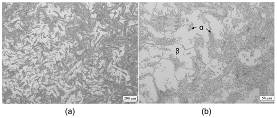
Figure 1.
Initial microstructures of the as-hot-rolled Ti-2Al-9.2Mo-2Fe alloy: (a) low and (b) high magnification.
The samples for microstructural observations were mechanically polished with a standard metallographic procedure, sand papers (#400–#2000), diamond paste (3 and 1 μm), and colloidal silica suspension (0.04 μm). The planes normal to the rolling direction were prepared. Microstructural observations of the alloy samples were performed on an optical microscope (OM, Zeiss Lab A1, Carl Zeiss, Essen, Germany), and a field emission scanning electron microscopy (FESEM, Zeiss GeminiSEM 500, Carl Zeiss, Jena, Germany) was operated at 20 kV. The initial samples for OM observations were etched in a solution of HF 2 vol.% + HNO3 10 vol.% + H2O 88 vol.%. EBSD mapping was also used to characterize the grain size and grain orientation of the solution-treated samples. The EBSD observations were carried out in an FESEM (Zeiss GeminiSEM 500, Carl Zeiss, Jena, Germany) operated at 20 kV and with a working distance of 15 mm. The step sizes used for the α/β-ST and β-ST samples were 0.2 and 1 μm, respectively.
The tensile samples with a gauge length of 30 mm and a diameter of 6 mm were machined from the heat-treated materials paralleling the rolling direction. The tensile tests were performed at room temperature (25 °C) using an INSTRON 5800 (Instron, Norwood, MA, USA) machine of 50 kN capacity with a constant strain rate of 5 × 10⁻⁴ s−1, determined by a contacted extensometer. Three samples of each condition were tested for an average value of property indexes, including ultimate tensile strength (UTS), yield strength (YS) (that is, 0.2% proof stress), total elongation (tEl), and uniform elongation (uEl). The fracture surfaces of the tensile-deformed samples were also observed using an FESEM (Zeiss GeminiSEM 500, Carl Zeiss, Jena, Germany) operated at 20 kV.
To understand the deformation mechanisms of the solution-treated samples, the samples were tensile-deformed till they reached a deformation of 4% and then cut along the tensile axis. The deformed samples were mechanically polished with sand papers (#400–#2000), diamond paste (3 and 1 μm) and colloidal silica suspension (0.04 μm). The deformed structures of the samples were characterized by using EBSD and electron channeling contrast imaging (ECCI). The EBSD observations were carried out in an FESEM (Zeiss GeminiSEM 500, Carl Zeiss, Jena, Germany) operated at 20 kV and with a working distance of 15 mm. The step sizes used for the deformed α/β-ST and β-ST samples were 0.2 and 0.5 μm, respectively. The ECCI observations were carried out in an FESEM (Zeiss GeminiSEM 500, Carl Zeiss, Jena, Germany) operated at 10 kV and with a working distance of 4 mm.
3. Results
3.1. Solution-Treated Microstructures
The microstructures of the alloy solution treated at different temperatures are shown in Figure 2. The sample solution treated at 790 °C exhibited a typical microstructure of β grains with a small number of primary α because the solution temperature was below the β-transus temperature. The primary α exhibited three kinds of morphologies: continuous and discontinuous layers along the grain boundaries and dot or bar type in the grain interiors, as shown in Figure 1a. On the contrary, the sample that was solution-treated at 850 °C exhibited an equiaxed structure of a single β with a grain size of ~35 μm, as shown in Figure 2b.
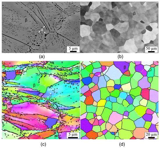
Figure 2.
SEM images and EBSD inverse pole figure (IPF) maps showing the microstructures of the alloy solution-treated for 1 h at: (a,c) 790 °C and (b,d) 850 °C. The black and white lines in (c,d) indicate the high- and low-angle boundaries, respectively.
EBSD observations revealed that the β grains in the α/β solution-treated sample still contained in-grain orientation gradients and a considerable amount of low-angle grain boundaries, as shown in Figure 2c. Only a few β grains are free of orientation gradients, which means that they are newly recrystallized grains. The β grains in the β solution-treated sample were nearly free of orientation gradients and surrounded by high-angle grain boundaries, indicating the occurrence of a complete recrystallization (Figure 2d). The equiaxed β grains had a grain size of ~35 µm.
3.2. Tensile Properties
Figure 3 shows the tensile stress–strain curves and strain-hardening behaviors of the solution-treated samples. The average values and standard deviations of tensile properties are summarized in Table 1. The alloy that was solution-treated below the transus temperature (α/β-ST) has a moderate strength of about 958 ± 14 MPa in UTS and 904 ± 12 Mpa in YS, and an elongation of approximately 20%. However, the alloy that was solution-treated above the transus temperature (β-ST) resulted in a slightly decreased strength of about 834 ± 12 Mpa and YS/UTS ratio of ~0.83 with an excellent ductility over 40% of elongation, as shown in Figure 3a.
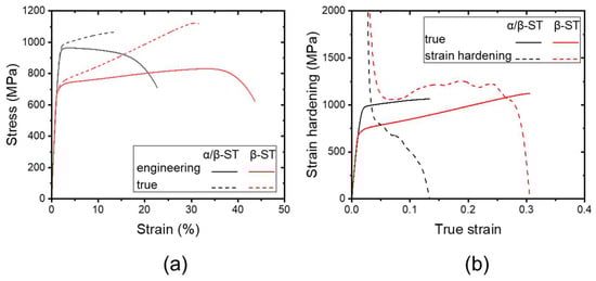
Figure 3.
Tensile stress–strain curves (a) and strain-hardening behavior (b) of the solution-treated alloy samples.

Table 1.
Tensile properties of 0.2% proof stress (YS), ultimate tensile strength (UTS), total elongation (tEl), and uniform elongation (uEl) of the samples.
The true stress (σt)–true strain (εt) curves and the corresponding work-hardening rate (θ = ∂σt/∂εt) curves are shown in Figure 3b. The strength and ductility difference between the two samples is related to the work-hardening behavior. A significant work hardening is observed in the β-ST sample, resulting in a superior ductility of over 40%. The strain hardening in the α/β-ST sample is only observed till the true strain of 0.15. The strain hardening in the β-ST sample remained at the high level of >1 Gpa from the strain of 0.05 to 0.25. Strain hardening is generally associated with the twinning-induced plasticity (TWIP) effect, which is the twinning mechanism that occurs in the metastable β phase [24,25].
The fracture surfaces of the tensile-tested samples after tensile testing are shown in Figure 4. Low-magnification images in Figure 4a showed that the α/β-ST sample exhibited a cup-and-cone morphology, indicating a typical ductile fracture. The SEM image in Figure 4b showed that very uniform dimples were formed in the sample after the tensile fracture. The dimples exhibited a size of a few microns in the α/β-ST sample. Low-magnification images in Figure 4c revealed that the β-ST sample exhibited a shear-type fracture. High-magnification images in Figure 4d revealed that there were also uniform dimples with a size of a few microns formed in the β-ST sample. In addition, the reduction in area in the β-ST sample is larger than that of the α/β-ST sample when compared to their initial areas. As a result, the true strains of the α/β-ST and β-ST samples after tensile the fractures were 0.05 and 0.38, respectively.
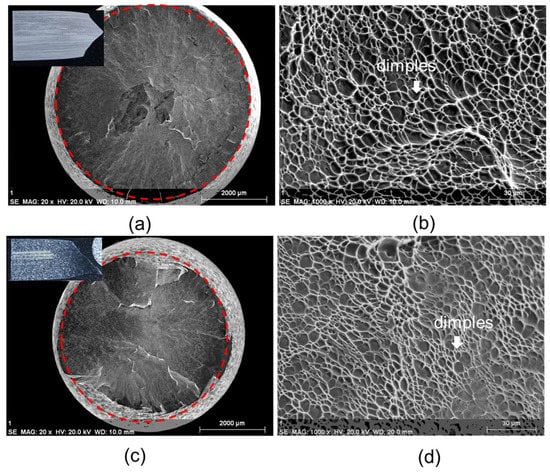
Figure 4.
Fracture surface observations of the tensile-tested alloy samples: (a,b) α/β-ST and (c,d) β-ST. Red dotted lines indicate the final diameters of the sample after tensile testing.
4. Discussion
To understand the microstructural evolution and plastic deformation mechanism, the deformed microstructures of the α/β-ST and β-ST samples were investigated and analyzed. The corresponding BSE, EBSD, and ECCI maps of the 4% tensile-deformed samples are shown in Figure 5, Figure 6 and Figure 7.
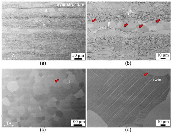
Figure 5.
BSE maps of the 4% deformed samples: (a,b) α/β-ST and (c,d) β-ST. TA pertains to the tensile axis. Red arrows indicate the formation of twinning.
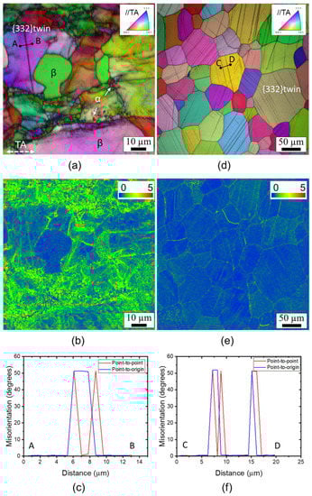
Figure 6.
EBSD IPF + image quality (IQ), kernel average misorientation (KAM), and misorientation line analyses of the 4% deformed samples: (a–c) α/β-ST and (d–f) β-ST. TA pertains to the tensile axis.
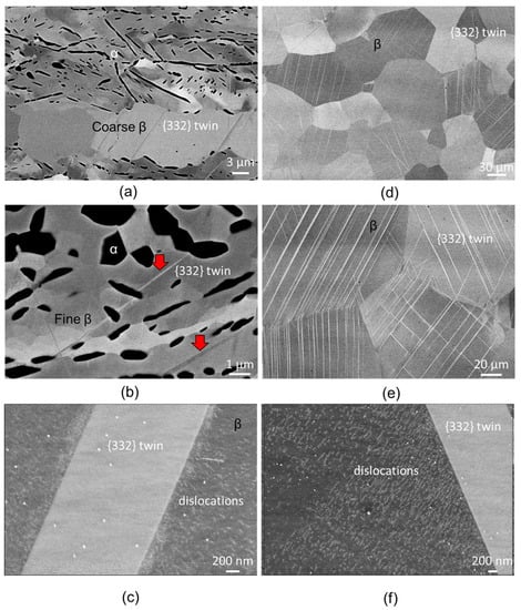
Figure 7.
ECC images showing the deformation structures and substructures of the 4% deformed samples: (a–c) α/β-ST and (d–f) β-ST. Red arrows indicate the formation of twinning.
4.1. Microstructural Evolution
Figure 5 shows the overall microstructures of the deformed samples after being tensile-deformed to 4%. The α/β-ST sample exhibited a layered structure, namely some layers consisted of only coarse β grains and others consisted of fine β ands α grains, as shown in Figure 5a,b. After the 4% deformation, there are no significant microstructural changes in the α/β-ST sample, as compared to its undeformed state (Figure 2a). Only a few line-like features can be observed in the layer of β grains because of the relatively small deformation strain. The β-ST sample after deformation still exhibited an equiaxed grain structure, as shown in Figure 5c; however, a considerable amount of plate-or-line- type deformation products can be observed in the equiaxed β grains. Considering the thickness of the deformation products, the thicker and thinner ones could be related to deformation twins and slip lines, respectively, as shown in Figure 5d. This needs EBSD observation to be verified.
4.2. Deformation Behavior
The EBSD inverse pole figure (IPF) + image quality (IQ), kernel average misorientation (KAM), and misorientation maps of the deformed samples are shown in Figure 6. It is observed that the layer with fine β and α grains is mainly deformed via the dislocation slip, whereas the layer with coarse β grains is mainly deformed via twinning, as shown in Figure 6a,d. KAM map in Figure 6b revealed that strain localization tends to occur in the fine grain layer; they are quite smaller in the layer of coarse β grains. The KAM map in Figure 6e revealed that the plastic deformation is relatively uniform except for the grain boundaries and twin boundaries. The misorientation analysis shown in Figure 6c,f revealed that the twin boundaries exhibited a misorientation of 50.5° along the <110> axis, which is a typical {332}<113> twinning system in bcc-Titanium. The formation of dislocation slips in the layer with fine β and α grains is because the fine β grains surrounded with α grains had a higher stability than that of the coarse β grains. However, the coarse β grains with lower stability caused the formation of {332}<113> twinning during deformation. It has been reported that the metastable β phase tends to deform via {332}<113> twinning in the beginning of plastic deformation [26,27].
Figure 7a showed that in the α/β-ST sample, the coarse β grain layer is deformed mainly via {332}<113> twinning, which is normally nucleated at the grain boundaries and terminated at another side of the grain boundaries. Additionally, {332}<113> twinning can be also observed in the fine β grain layer that had few α grains, probably because this region still has lower stability, as indicated by the arrows in Figure 7b. Twinning cannot be observed in the regions with a high fraction of α grains. In addition, individual dislocations are also observed in the β matrix, and dislocation accumulation can be found at the {332}<113> twin boundaries, as shown in Figure 7c.
The β-ST sample without any α phase exhibited the lowest stability compared to the α/β-ST sample. Therefore, they were deformed mainly via {332}<113> twinning, as shown in Figure 7d. Figure 7e indicated that multiple twin variants (twin systems) occurred in some β grains. Individual dislocations can also be found in the matrix and dislocation accumulation that occurred at the twin boundaries, as shown in Figure 7f. The frequent occurrence of {332}<113> twinning in the β-ST sample resulted in a higher fraction of twin boundaries, which contributed higher strain hardening via dynamic grain refinement. This rendered the sample highly ductile.
5. Conclusions
In the present study, the deformation behavior of the tensile properties and the work-hardening behavior in a β-type Ti-2Al-9.2Mo-2Fe alloy have been investigated. The main results are summarized below:
- (1)
- The β-solution-treated alloy exhibited a single β phase with a lower β stability. However, the α/β-solution-treated alloy exhibited a layered structure, consisting of fine α + β grain layers and coarse β grain layers, and the β in the coarse grain layer had a lower stability but the β in the fine grain layer had a higher stability, owing to its coexistence with α;
- (2)
- The β-solution-treated alloy was mainly deformed via {332}<113> deformation twinning, thus showing very high ductility, uniform elongation of approximately 35%;
- (3)
- The α/β-solution-treated alloy was deformed via two mechanisms, namely {332}<113> deformation twinning in the coarse grain layers and dislocation slip in the fine grain layers. The α/β-solution-treated alloy exhibited high strength with lower ductility due to the small amount of deformation twinning.
Author Contributions
Conceptualization, W.T.; methodology, X.Z.; validation, C.Y.; formal analysis, L.W. and H.Z.; investigation, X.Z.; data curation, C.Y.; writing—original draft preparation, W.T.; writing—review and editing, C.L.; visualization, X.Z.; supervision, C.L.; project administration, C.L.; funding acquisition, C.L. All authors have read and agreed to the published version of the manuscript.
Funding
This research was funded by the Natural Science Foundation of Hubei Province of China, grant number 2022CFB016 and the APC was funded by Aerospace Precision Products Co. Ltd., Tianjin, China.
Data Availability Statement
Not applicable.
Conflicts of Interest
The authors declare no conflict of interest.
References
- Williams, J.C.; Starke, E.A. Progress in structural materials for aerospace systems. Acta Mater. 2003, 51, 5775–5799. [Google Scholar] [CrossRef]
- Banerjee, D.; Williams, J.C. Perspectives on titanium science and technology. Acta Mater. 2013, 61, 844–879. [Google Scholar] [CrossRef]
- Geetha, M.; Singh, A.K.; Asokamani, R.; Gogia, A.K. Ti based biomaterials, the ultimate choice for orthopaedic implants—A review. Prog. Mater. Sci. 2009, 54, 397–425. [Google Scholar] [CrossRef]
- Chen, Q.; Thouas, G.A. Metallic implant biomaterials. Mater. Sci. Eng. R Rep. 2015, 87, 1–57. [Google Scholar] [CrossRef]
- Kolli, R.P.; Devaraj, A. A Review of Metastable Beta Titanium Alloys. Metals 2018, 8, 506. [Google Scholar] [CrossRef]
- Zhang, L.-C.; Chen, L.-Y. A Review on Biomedical Titanium Alloys: Recent Progress and Prospect. Adv. Eng. Mater. 2019, 21, 1801215. [Google Scholar] [CrossRef]
- Kang, L.; Yang, C. A Review on High-Strength Titanium Alloys: Microstructure, Strengthening, and Properties. Adv. Eng. Mater. 2019, 21, 1801359. [Google Scholar] [CrossRef]
- Zhao, G.-H.; Xu, X.; Dye, D.; Rivera-Díaz-Del-Castillo, P.E. Microstructural evolution and strain-hardening in TWIP Ti alloys. Acta Mater. 2020, 183, 155–164. [Google Scholar] [CrossRef]
- Devaraj, A.; Joshi, V.V.; Srivastava, A.; Manandhar, S.; Moxson, V.; Duz, V.A.; Lavender, C. A low-cost hierarchical nanostructured beta-titanium alloy with high strength. Nat. Commun. 2016, 7, 11176. [Google Scholar] [CrossRef]
- Liu, H.; Niinomi, M.; Nakai, M.; Cho, K.; Fujii, H. Deformation-induced ω-phase transformation in a β-type titanium alloy during tensile deformation. Scr. Mater. 2017, 130, 27–31. [Google Scholar] [CrossRef]
- Chen, W.; Yu, G.; Li, K.; Wang, Y.; Zhang, J.; Sun, J. Plastic instability in Ti–6Cr–5Mo–5V–4Al metastable β-Ti alloy containing the β-spinodal decomposition structures. Mater. Sci. Eng. A 2021, 811, 141052. [Google Scholar] [CrossRef]
- Murzinova, M.A.; Zherebtsov, S.V.; Klimenko, D.N.; Semiatin, S.L. The Effect of β Stabilizers on the Structure and Energy of α/β Interfaces in Titanium Alloys. Met. Mater. Trans. A 2021, 52, 1689–1698. [Google Scholar] [CrossRef]
- Ji, X.; Gutierrez-Urrutia, I.; Emura, S.; Liu, T.; Hara, T.; Min, X.; Ping, D.; Tsuchiya, K. Twinning behavior of orthorhombic-α” martensite in a Ti-7.5Mo alloy. Sci. Technol. Adv. Mater. 2019, 20, 401–411. [Google Scholar] [CrossRef] [PubMed]
- Ji, X.; Emura, S.; Min, X.; Tsuchiya, K. Strain-rate effect on work-hardening behavior in β-type Ti-10Mo-1Fe alloy with TWIP effect. Mater. Sci. Eng. A 2017, 707, 701–707. [Google Scholar] [CrossRef]
- Li, C.L.; Ye, W.J.; Mi, X.J.; Hui, S.X.; Lee, D.G.; Lee, Y.T. Development of Low Cost and Low Elastic Modulus of Ti-Al-Mo-Fe Alloys for Automotive Applications. Key Eng. Mater. 2013, 551, 114–117. [Google Scholar] [CrossRef]
- Lee, D.-G.; Li, C.; Lee, Y.; Mi, X.; Ye, W. Effect of temperature on grain growth kinetics of high strength Ti–2Al–9.2Mo–2Fe alloy. Thermochim. Acta 2014, 586, 66–71. [Google Scholar] [CrossRef]
- Li, C.-L.; Mi, X.-J.; Ye, W.-J.; Hui, S.-X.; Lee, D.-G.; Lee, Y.-T. Influence of heat treatment on microstructure and tensile property of a new high strength beta alloy Ti–2Al–9.2Mo–2Fe. Mater. Sci. Eng. A 2013, 580, 250–256. [Google Scholar] [CrossRef]
- Li, C.-L.; Mi, X.-J.; Ye, W.-J.; Hui, S.-X.; Lee, D.-G.; Lee, Y.-T. Microstructural evolution and age hardening behavior of a new metastable beta Ti–2Al–9.2Mo–2Fe alloy. Mater. Sci. Eng. A 2015, 645, 225–231. [Google Scholar] [CrossRef]
- Li, C.; Lee, D.-G.; Mi, X.; Ye, W.; Hui, S.; Lee, Y. Effect of Al Addition on ω Precipitation and Age Hardening of Ti-Al-Mo-Fe Alloys. Met. Mater. Trans. A 2016, 47, 2454–2461. [Google Scholar] [CrossRef]
- Chen, R.; Tan, C.; Yu, X.; Hui, S.; Ye, W.; Lee, Y. Effect of TiB particles on the beta recrystallization behavior of the Ti-2Al-9.2Mo-2Fe-0.1B metastable beta titanium alloy. Mater. Charact. 2019, 153, 24–33. [Google Scholar] [CrossRef]
- Xiao, J.; He, B.; Tan, C. Effect of martensite on {332} twinning formation in a metastable beta titanium alloy. J. Alloys Compd. 2022, 895, 162598. [Google Scholar] [CrossRef]
- Ji, J.; Li, Z.; Ren, Y.; Tan, C. Adiabatic Shearing Behavior of Shock-Prestrained Ti-2Al-9.2Mo-2Fe Alloy at Different Reloading Strain Rates. J. Phys. Conf. Ser. 2021, 1855, 12007. [Google Scholar] [CrossRef]
- Li, C.-L.; Narayana, P.; Reddy, N.; Choi, S.-W.; Yeom, J.-T.; Hong, J.-K.; Park, C.H. Modeling hot deformation behavior of low-cost Ti-2Al-9.2Mo-2Fe beta titanium alloy using a deep neural network. J. Mater. Sci. Technol. 2018, 35, 907–916. [Google Scholar] [CrossRef]
- Gutierrez-Urrutia, I.; Li, C.-L.; Emura, S.; Min, X.; Tsuchiya, K. Study of {332}<113> twinning in a multilayered Ti-10Mo-xFe (x = 1–3) alloy by ECCI and EBSD. Sci. Technol. Adv. Mater. 2016, 17, 220–228. [Google Scholar] [CrossRef]
- Gutierrez-Urrutia, I.; Li, C.-L.; Ji, X.; Emura, S.; Tsuchiya, K. Quantitative analysis of {332}<113> twinning in a Ti-15Mo alloy by in situ scanning electron microscopy. Sci. Technol. Adv. Mater. 2018, 19, 474–483. [Google Scholar] [CrossRef] [PubMed]
- Tobe, H.; Kim, H.Y.; Inamura, T.; Hosoda, H.; Miyazaki, S. Origin of {332} twinning in metastable β-Ti alloys. Acta Mater. 2014, 64, 345–355. [Google Scholar] [CrossRef]
- Min, X.H.; Tsuzaki, K.; Emura, S.; Sawaguchi, T.; Ii, S.; Tsuchiya, K. {332} ⟨113⟩ Twinning system selection in a β-type Ti–15Mo–5Zr polycrystalline alloy. Mater. Sci. Eng. A 2013, 579, 164–169. [Google Scholar] [CrossRef]


Disclaimer/Publisher’s Note: The statements, opinions and data contained in all publications are solely those of the individual author(s) and contributor(s) and not of MDPI and/or the editor(s). MDPI and/or the editor(s) disclaim responsibility for any injury to people or property resulting from any ideas, methods, instructions or products referred to in the content. |
© 2023 by the authors. Licensee MDPI, Basel, Switzerland. This article is an open access article distributed under the terms and conditions of the Creative Commons Attribution (CC BY) license (https://creativecommons.org/licenses/by/4.0/).