Article

Microhardness and Microstructural Evolution of Pure Nickel Processed by High-Pressure Torsion

1
Key Laboratory of Micro-Systems and Micro-Structures Manufacturing of Ministry of Education, Harbin Institute of Technology, Harbin 150080, China
2
School of Materials Science and Engineering, Harbin Institute of Technology, Harbin 150001, China
3
Materials Research Group, Department of Mechanical Engineering, University of Southampton, Southampton SO17 1BJ, UK
*
Author to whom correspondence should be addressed.
Crystals 2023, 13(6), 887; https://doi.org/10.3390/cryst13060887
Submission received: 5 May 2023 / Revised: 24 May 2023 / Accepted: 24 May 2023 / Published: 28 May 2023
(This article belongs to the Special Issue Crystal Plasticity (Volume III))

Abstract

:
High-purity Ni was processed by high-pressure torsion (HPT) at room temperature under an imposed pressure of 6.0 GPa and a rotation rate of 1 rpm through 1/4 to 10 turns, and samples were then examined using Electron Back-Scattered Diffraction (EBSD) and microhardness measurements. The results show that the grain size and low-angle grain boundaries (LAGBs) gradually decrease with the growth of HPT revolutions while the microhardness values gradually increase. After 10 turns of HPT processing, ultrafine-grained (UFG) pure Ni with a reasonable microhardness value and microstructure homogeneity can be achieved across the disk, thereby giving great potential for applications in micro-forming. A grain refinement model for severe plastic deformation (SPD) of pure Ni is proposed.

1. Introduction

With the increasing demand for high-performance materials in industry, especially for micro-structures and micro-components, there has been considerable interest in strengthening metal materials [1,2]. It is generally recognized that solid solution strengthening, work hardening, phase change strengthening, precipitation strengthening, dispersion strengthening, and other methods need to enhance one performance at the expense of another performance or even two performances. In particular, fine-grain strengthening shows that a decrease in grain size can significantly improve the strength, hardness, ductility, and toughness of the material. It not only enhances several conflicting properties at the same time but also has the best strengthening effect [3,4]. Therefore, the use of ultrafine-grained (UFG) materials has the potential to produce micro-miniature parts with superior properties. Compared with unprocessed coarse grain (CG) samples, UFG materials generally have more excellent physical properties, mechanical properties, and forming properties [5,6,7,8,9]. For example, its flow stress during deformation at high temperatures should be significantly reduced, and at the same time, there are also excellent applications in the field of superplasticity [10,11]. Recently, a series of reports showed that SPD could produce materials that combine high strength and high ductility [12,13]. More importantly, because UFG materials have smaller characteristic sizes that are orders of magnitude smaller than in micro-parts, they can significantly reduce the “scale effect” of the micro-forming processing. Therefore, they are extremely effective in the filling of micro-parts and improving the quality of the formed components [14,15]. It is reasonable to anticipate that the inhomogeneous shape evolution should be significantly reduced compared with CG materials [16,17]. With the development of SPD technology, UFG, and nanocrystalline materials have gradually been applied to micro-forming technology, such as electronics and biomedical products that require more functions and smaller volumes [18]. Therefore, UFG materials have excellent application potential in micro-forming technology.
SPD is widely used to prepare UFG materials [19,20]. SPD has the ability to result in a very significant refinement in the grain size of various pure metals and alloys [21,22]. Because SPD makes the equivalent strain of the material generally greater than two while the traditional plastic processing technology makes the equivalent strain of the material generally less than two, SPD produces greater plastic deformation than the conventional plastic deformation method. Thus, the grain size of various materials (<1 µm) can be sufficiently refined. At the same time, the shape and size of the material before and after forming do not change significantly because of the mold shape and hydrostatic pressure. There are many SPD processing techniques to prepare UFG materials, but HPT is one of the most promising processing technologies. HPT is not only simple but also has the potential to refine the microstructures of metals and alloys to the submicrometer or even the nanometer range [23,24,25,26]. For example, experiments on an Al–3% Mg solid solution alloy gave a grain size of ~90 nm after HPT processing at room temperature [27], whereas a similar alloy processed by equal-channel angular pressing (ECAP) at room temperature gave a grain size of ~270 nm [28]. Furthermore, the proportion of high-angle grain boundaries (HAGBs) of materials produced by HPT is higher. High pressure can generate high strain, so there are no problems with destroying the sample, and also, there is a suppression of porosity and defects. Thus, HPT can obtain ideal UFG materials, which greatly promotes the development of micro-forming technology. However, there remains a lack of investigations on the improvement of the properties of pure Ni processed by HPT.
Pure Ni is widely used in machinery, electronics, chemicals, and other industries because of its excellent corrosion resistance and heat resistance. Thus, in order to further improve the application performance of pure Ni, the present research attempts to use HPT processing to prepare UFG pure Ni material with submicrometer grain size through a combination of experiment, theory, and model research methods. This report is aimed at exploring the manner in which the HPT processing affects the microstructure and the microhardness of pure Ni. Meanwhile, the grain refinement mechanism was also analyzed. As will be demonstrated, the experimental results offer a theoretical foundation for the application of UFG materials in the field of micro-forming technology.

2. Materials and Methods

2.1. High-Pressure Torsion Processing Route

High-purity Ni was selected as the material for this experiment. In order to obtain a uniform initial structure and eliminate the internal stress generated, these samples need to be annealed at 700 °C for 2 h before cutting. The annealed structure of the pure Ni sample was observed by a Scanning Electron Microscope (SEM, Quanta 200FEG, FEI company, Hillsboro, OR, USA20 kV), as shown in Figure 1a. It is shown that under annealing conditions, the grain size is coarse, and the grains are obviously inhomogeneous. To prepare specimens, the as-received plates were machined into disks with diameters of 10 mm and thicknesses of ~1.0 mm by wire cutting, and these disks were then ground on SiC papers to final thicknesses of ~0.82 mm.
Figure 1b schematically depicts the HPT processing. The device is mainly composed of upper and lower anvils with circular grooves. A disk is placed between two anvils, and then the lower anvil is twisted at a high pressure of 6.0 GPa with a rotation rate of 1 rpm at room temperature to cause shear deformation. Therefore, the HPT processing produces both shear and normal strain in the pure Ni. The process parameters are displayed in Table 1.
Figure 1c shows the pure Ni samples with different turns processed by HPT. The impact of the accumulated strain is assessed by 1/4, 1, 5, and 10 turns. The thickness of the sample is greater than the sum of the heights of the upper and lower die grooves, and the HPT processing is carried out under isostatic pressure. Therefore, when high pressure is applied to the pure Ni sample, a small amount of the material will flow out due to the compression between the two anvils. This procedure is designated quasi-constrained HPT [29]. After the flash is removed, the shape of the sample is a relatively regular round flat piece. HPT is processed under a large load. The frictional force generated by the upper and lower molds on the surface represents a large torsion force that causes the disk to be twisted and deformed. After HPT processing, the surface leaves a rotation mark, which is helpful in determining the center position of the disk.

2.2. Microhardness Test

The original disks and the experimental disks after HPT deformation were polished to 1200# using abrasive papers, and then they were mechanically polished to mirror-like surfaces. A Vickers microhardness tester (HVS-1000A, Huayin company, China: Laizhou) was used for the microhardness testing with a load of 500 g and a dwell time of 10 s. In addition, the deformation of different positions in the disk is different, so it is necessary to test the hardness values of different positions of the sample. Accurate microhardness measurements were performed manually on the samples following a rectilinear grid pattern and with incremental steps of 0.3 mm between each measurement. The average values were calculated. To gather specific information regarding the changes in microhardness, two different methodologies were applied. First, hardness values were extracted on two mutually perpendicular diameters, and an average calculation was performed to obtain the hardness value distribution along the diameter. Second, color-coded contour maps were created based on the measured hardness values to show the direct hardness distributions across a one-quarter area of the disks.

2.3. EBSD Measurement

In order to analyze the microstructural evolution during HPT, it is necessary to obtain detailed information on the microstructures. Therefore, the grain structures of the UFG Ni processed by HPT were further characterized by the electron back-scattered diffraction (EBSD: Quanta 200FEG field emission SEM, FEI company, Hillsboro, OR, USA) and analyzed using a TSL orientation imaging microscopy (OIM) system. In order to obtain a satisfactory surface, the micro-samples were electro-polished to mirror-like surfaces. The edge, the mid-radius position (2.5 mm from the center), and the center of the disc were used as test locations.

3. Results

3.1. Microhardness Evolution of HPT-Processed Pure Ni

The Vickers microhardness distribution along the diameter and the Vickers microhardness throughout the surfaces of the HPT processed samples were plotted after various numbers of turns. It is shown in Figure 2 that the hardness values of pure Ni are symmetrical about the center of the sample after HPT processing. However, the distribution of microhardness is non-uniform across the sample diameter. When the number of turns is low, the hardness in the central region is lower than in either the mid-radius region or the edge region of the sample. It is generally recognized that the hardness value fluctuates greatly, which indicates that the internal structure of the material is extremely inhomogeneous. However, with increasing applied turns, the microhardness measured at the central region increases significantly and gradually approaches the value at the edge. The hardness homogenization of the disk increases. This is due to microstructure refinement, which is strongly influenced by the region of the sample. After 10 turns of HPT treatment, the hardness of the sample showed better uniformity, except for a slight upward trend from the center to the edge of the disk.
The average microhardness value of the entire disk after HPT processing was higher than that of the annealed sample. The hardness of the edge increased rapidly after 1/4 turn of HPT processing. However, with the number of turns increasing, the changes in the hardness of the edge were less. The hardness at the edge after one turn of HPT is stable and reaches a saturation value of ~375 Hv. The hardness at the center continued to increase with the increase in the number of turns and gradually approached the saturation value. The increase was smaller after 1/4 t and 1 t, while there was a significant increase after 5 t and 10 t. It was about three times the value of the annealed pure Ni after ten turns of HPT processing. There was no obvious change across the disk surface with a hardness of ~375 Hv. Therefore, when the hardness values of the samples become saturated, the strengthening effect brought by further increasing the number of turns becomes very limited. The present results are consistent with some earlier reports on the processing of high-purity Cu by HPT [30].
In order to further study the development of uniformity, Figure 3 provides displays of microhardness over a one-quarter area of the disk surfaces processed by a 1/4, b 1, c 5, and d 10 turns of HPT. Randomly selected Cartesian coordinates X and Y were placed on the surface of each disk so that the center of each disk was at the point (0,0). The color in Figure 3 corresponds to the color scale shown at the lower right, where the range of the hardness values is 100 to 400 in incremental steps of 50. It can be clearly observed that the values of the microhardness increase with increasing distance from the center of the disk. As the number of turns increases, the size of the region with lower hardness decreases. After HPT processing, there is a higher level of hardness values and a general hardness homogeneity. At ten turns, the distribution of the microhardness values on the disk is very homogeneous, and the average microhardness value is as high as 375 Hv. These results are consistent with the results on the hardness distribution of the disk shown in Figure 2, but they provide a more detailed description.

3.2. Microstructure Evolution of HPT-Processed Pure Ni

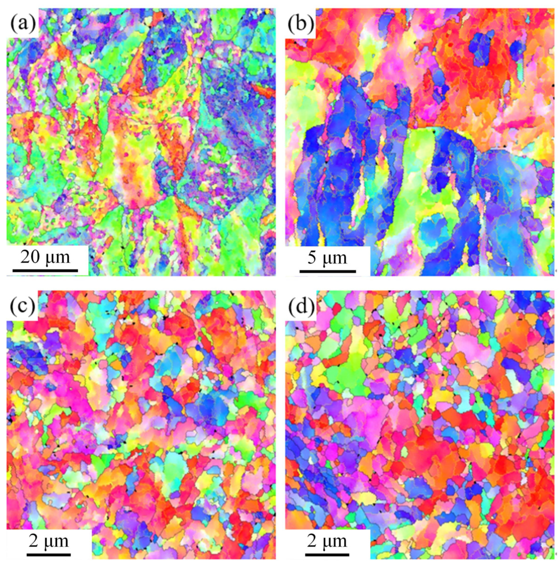
Figure 4 shows the central structures of HPT-processed samples with different turns. Under ideal conditions, there is no shear strain in the center of the disks. However, the misorientation angles of the crystal grains change during HPT processing, resulting in deformation in the central region of the samples. After processing through a one-quarter turn, the micrograph shows that the shear strain is limited, so its impact on the grains is small. As shown in Figure 4a, the grains are refined but still coarse. Measurements give average grain sizes of 1.42 µm. Many LAGBs (yellow lines, 2–15°) are formed inside the large grains, indicating that substructures are produced due to the geometric requirements of strain. There are many different colors in the large grains, indicating that the orientations of the substructures are different. The microstructure after one turn of HPT is shown in Figure 4b. The grain size is greatly decreased to 0.59 µm, but the microstructure is still inhomogeneous. There are many small grains formed by HAGBs among the coarse grains. In Figure 4c, when the number of turns is five, the grain size is refined to 0.35 µm, and the original grain boundaries are not visible. Finally, the grain size is slightly reduced to 0.33 µm, reaching a stable value after ten turns, as shown in Figure 4d. However, there are still large grains in the disks.
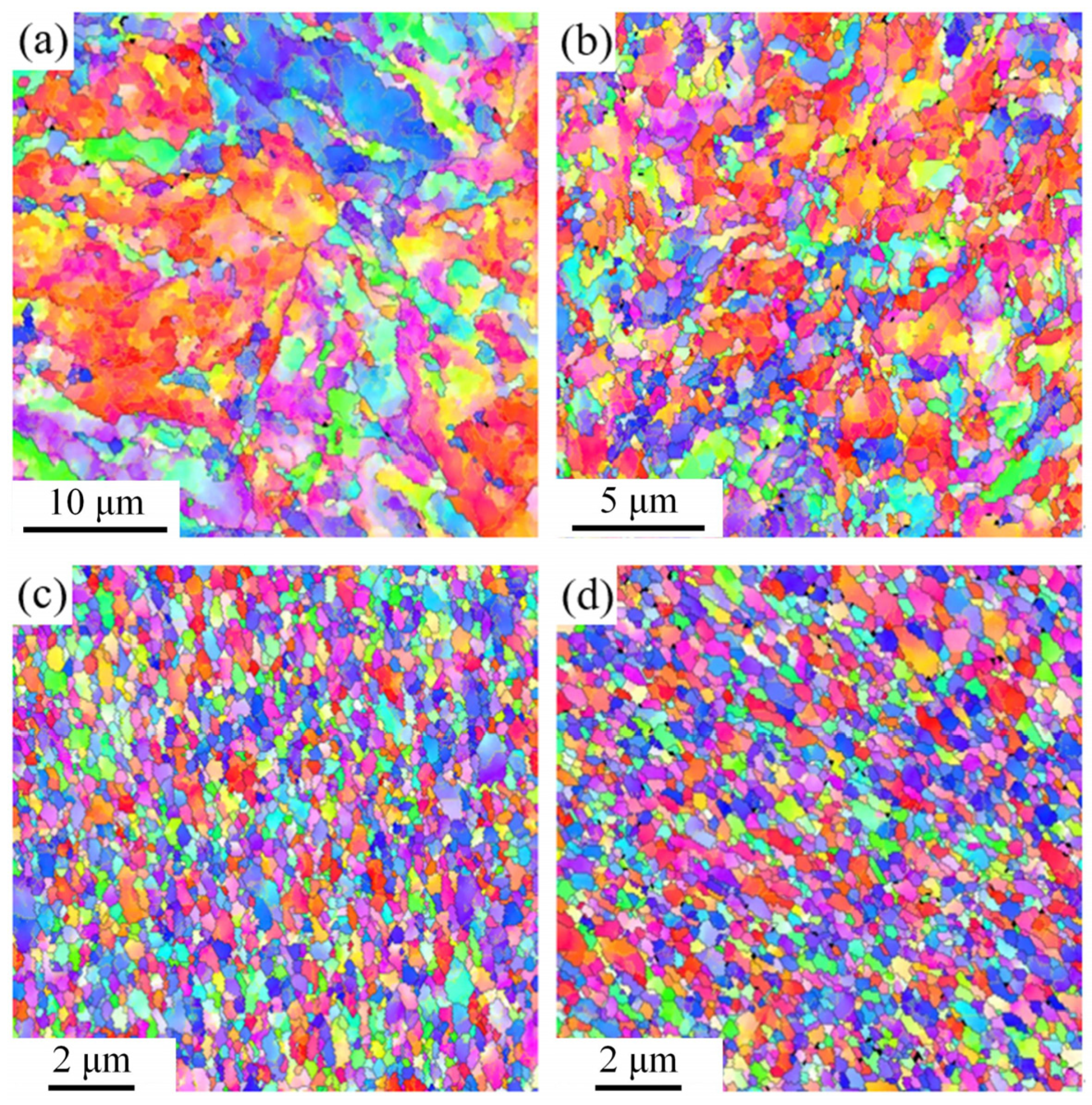
The structures of the mid-radius position corresponding to 2.5 mm from the center of the disks with different turns are shown in Figure 5. As shown in Figure 5a, after HPT processing through a quarter turn, the original grains were broken and refined to 0.81 µm. They are UFG materials, but the structure is not homogenous enough. They are composed of coarse grains and fine grains, and many HAGBs and LAGBs are produced in the coarse grains. The existence of many different colors indicates that there are great differences in the misorientation angles of the substructures. Figure 5b shows that the accumulated strain has increased sufficiently to cause noticeable microstructural changes after one turn of HPT processing. The microstructure is refined, and the grain size is 0.39 µm. The original grain boundaries nearly disappear, and the LAGBs are gradually transformed into HAGBs. As shown in Figure 5c, after five turns of HPT, the strain during HPT processing increases to a certain extent, and the average grain size decreases to 0.23 µm. The grain distribution becomes very homogenous, terminating ultimately in an equiaxed shape. Furthermore, the HAGBs are still increasing. As shown in Figure 5d, when it reaches ten turns, the microstructure changes little, and the grain size is slightly decreased to 0.22 µm. The increase in the HAGBs is small, reaching saturation. The results show a reasonable homogeneity of the microstructure and good material properties.
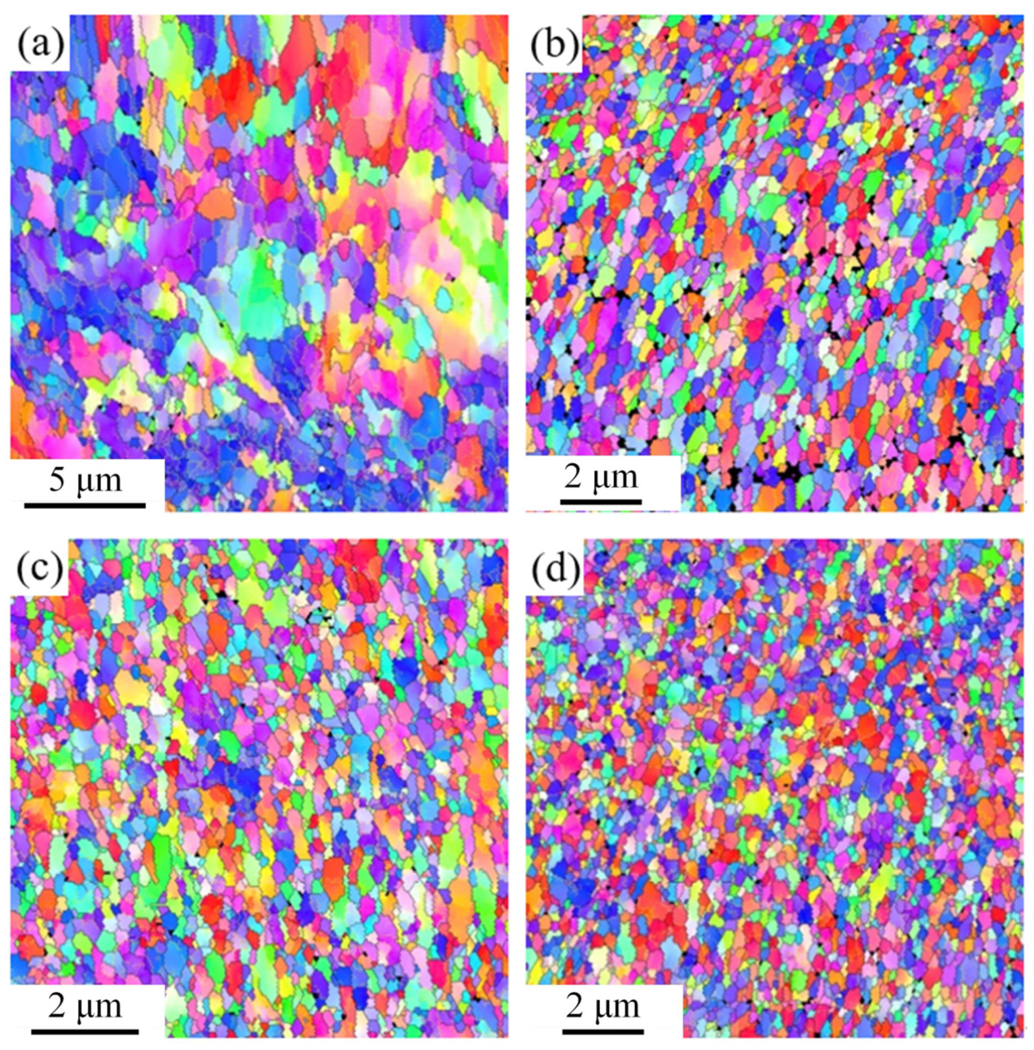
Figure 6 shows the edge structures of HPT-processed samples with different turns obtained by EBSD, which is similar to the center of the disk. In Figure 6a, after a one-quarter turn, the edge region is subjected to more shear strain compared to the central region and the mid-radius region, and the grains are refined to a certain extent. At this time, the microstructure has become refined to UFG but is not homogenous enough. The larger crystal grains have a smooth transition in color change, indicating that there are low-angle boundaries. Figure 6b shows the microstructure after one turn of HPT. The grain size is further decreased to 0.26 µm, and the microstructure is relatively homogeneous. After five turns in Figure 6c, the microstructure tends to become more uniform and with an average grain size of 0.22 µm. Finally, as shown in Figure 6d, after ten turns of HPT processing, UFG pure Ni with an average grain size of 0.21 µm is obtained. The grain size and the uniformity of the microstructure have not changed much. Furthermore, the grain size is basically uniform. The results of these structural observations show that after five or more turns of HPT processing, the microstructure of pure Ni becomes quite homogenous.
From the comparative and qualitative analyses in Figure 4, Figure 5 and Figure 6 the degree of grain refinement varies at different positions of the disc after HPT processing. Table 2 provides a detailed summary of the measurements of grain size. The grain size of the material decreases with increasing numbers of turns during HPT processing. After 1/4 turn of HPT, the crystal grains are fragmented to a certain extent, and the grain size is still large. When the number of turns is one, the grain size in the center region is large, while the grains at the edge are largely fragmented. The grains have been significantly refined after five turns of HPT, and the average grain size at the edge of the sample is about 0.23 µm. After ten turns of HPT, the grains at the center and edge of the sample have been sufficiently refined, and the grain size at the edge reaches 0.22 µm. Furthermore, the mean grain size in the center of the sample is the largest, and the edge region is the smallest. After one-quarter turn of HPT processing, the grain size in the center of the sample is close to three times that of the edge area. The microstructure near the edge of the disk has a higher degree after HPT processing of refinement, but as the number of turns increases, the difference gradually decreases. It is readily apparent that when the number of turns reaches 5, the difference in grain size is small, but the central position of the sample still cannot be refined to the same extent as the edge position. The uniformity of 10 turns of HPT is the optimum, and the microstructures at different positions of the disk are then quite similar.
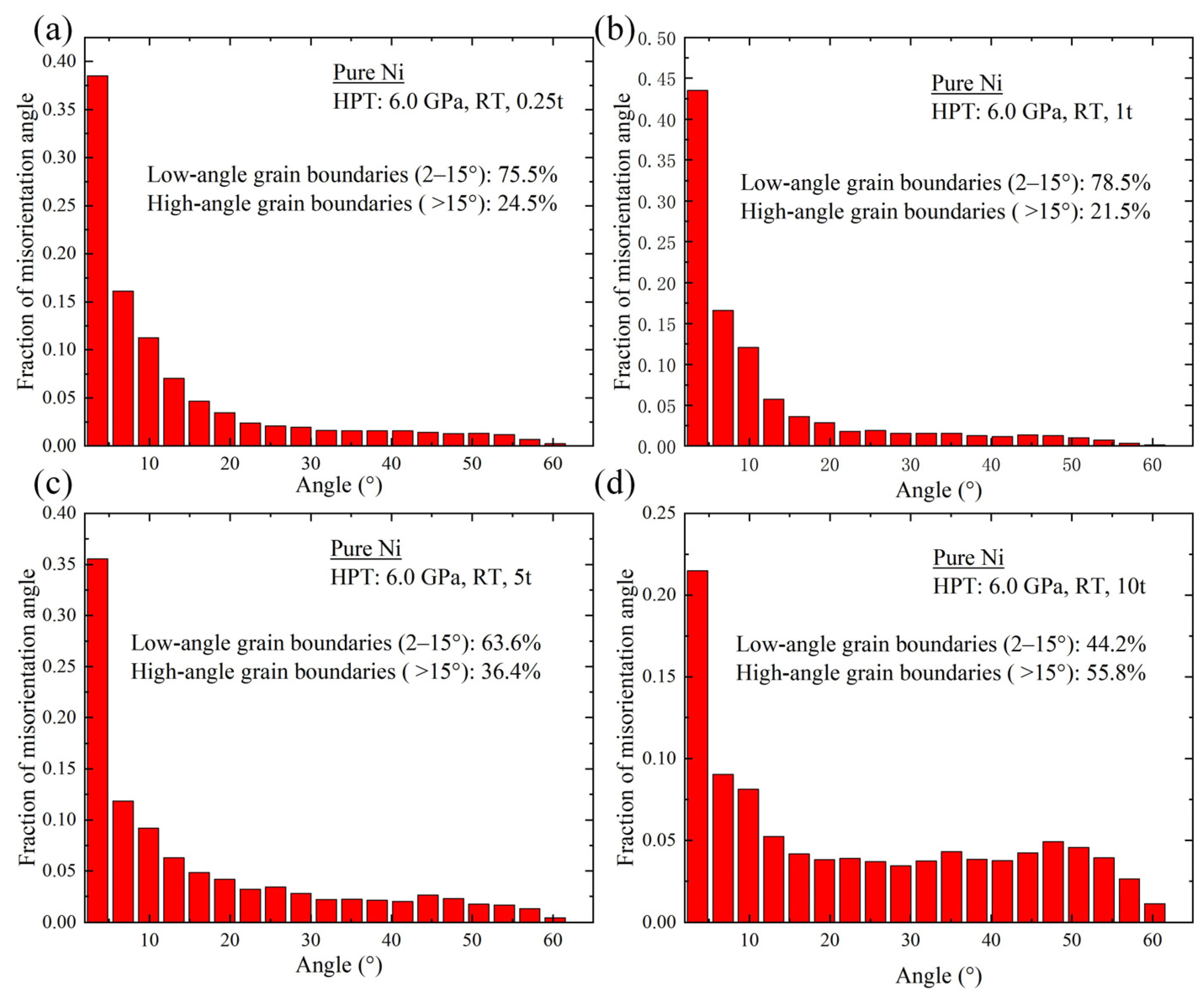
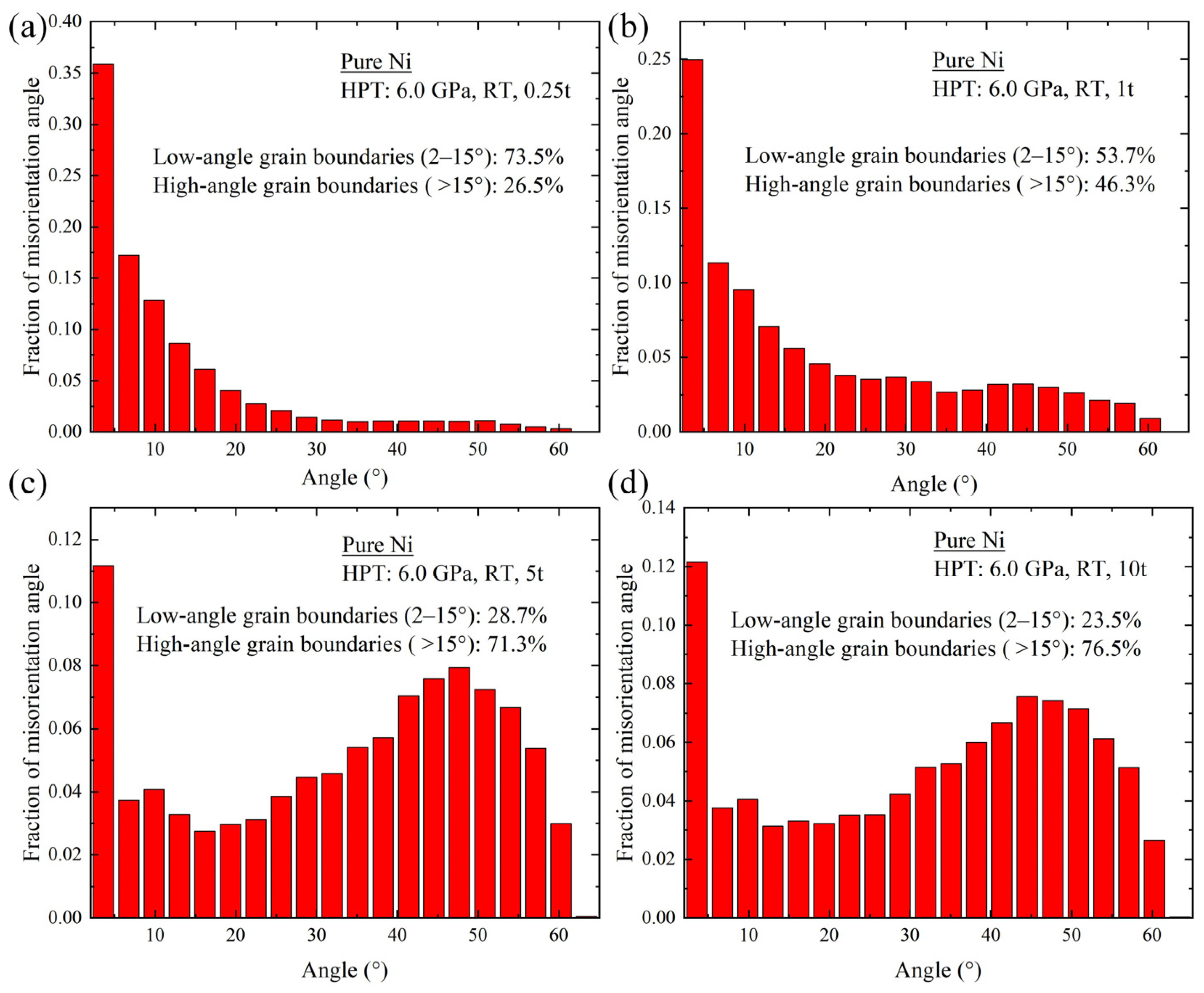
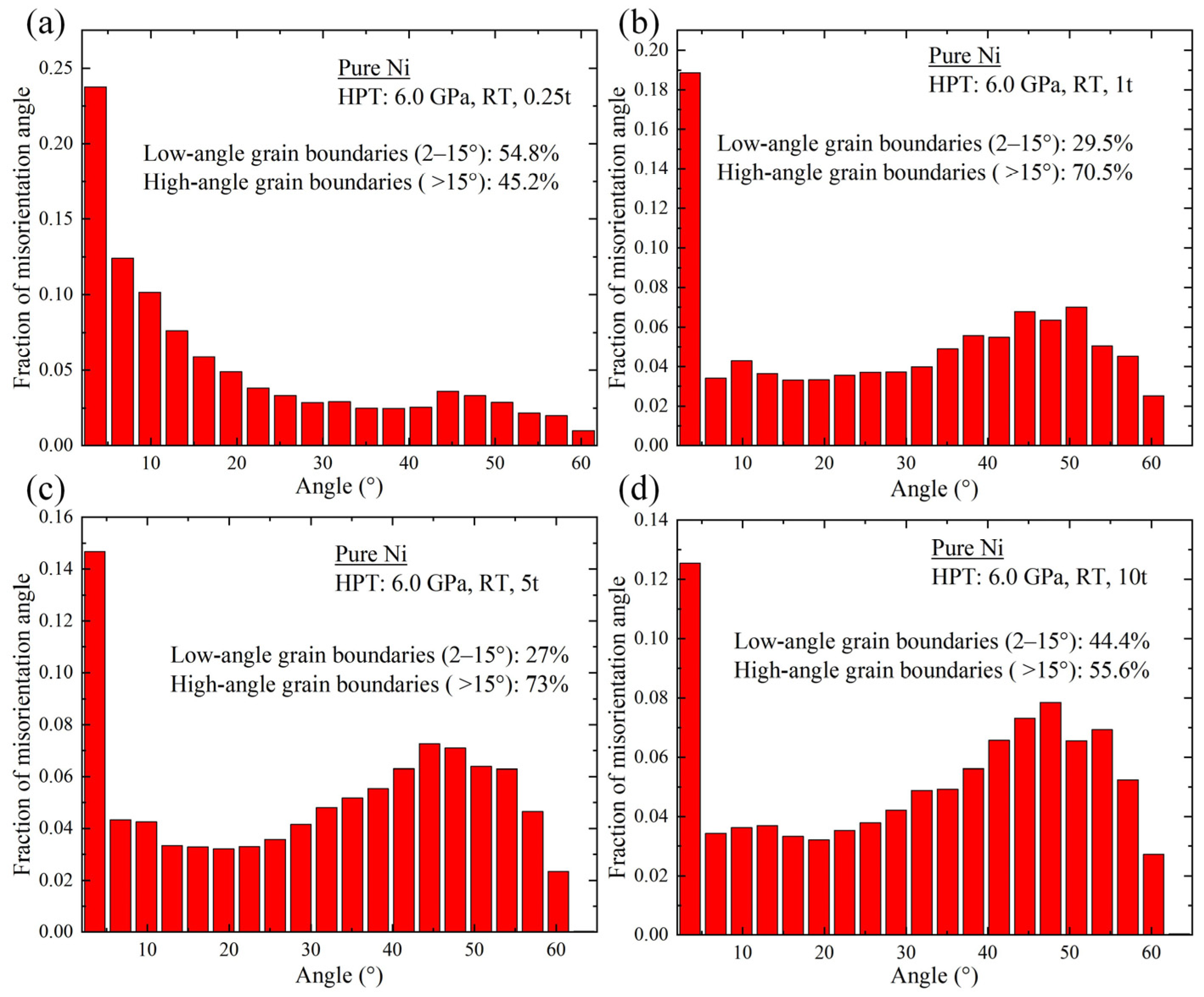
By drawing a histogram, it is possible to understand the laws of misorientation angles during HPT processing, as shown in Figure 7, Figure 8, and Figure 9.
Figure 7, Figure 8, and Figure 9, respectively, show histograms of the misorientation angles in the center region, the mid-radius position corresponding to 2.5 mm from the center of the annealed samples, and the edge position after the HPT processing with different turns. Figure 7a,b show that there are 75.5% and 78.5% LAGBs in the microstructures of the samples processed by one-quarter turn and one turn of HPT, and a high proportion of LAGBs is formed in the early stages of HPT processing. However, as the number of HPT turns increases, it gradually evolves towards HAGBs. As shown in Figure 7c,d, the fractions of LAGBs gradually decrease to 63.6% and 44.2% after 5 t and 10 t due to the high strain deformation.
The histograms corresponding to the number of turns shown in Figure 8 and Figure 9 have basically the same appearance, which proves that the microstructures between the mid-radius position and the edge position of the disk are similar under these experimental conditions.
Comparing Figure 7, Figure 8, and Figure 9, the results show that at the edge, the speed of the evolution to HAGBs is faster because of the higher strain. The law of the grain boundary angles at different positions of the sample is roughly the same. It is apparent that with the increase in the number of turns, the LAGBs of the sample generally decrease with an increase of the deformation, and they turn into HAGBs. The proportion of LAGBs is high under a small amount of deformation, while the proportion of HAGBs is high under a large amount of deformation. When it reaches ten turns, the proportion of HAGBs at the edge of the sample reaches 76.3%. Furthermore, the proportion of HAGBs in the center of the sample is the smallest, while in the edge region, it is the largest after HPT processing.

3.3. Equivalent Strain vs. Microhardness of HPT-Processed Pure Ni

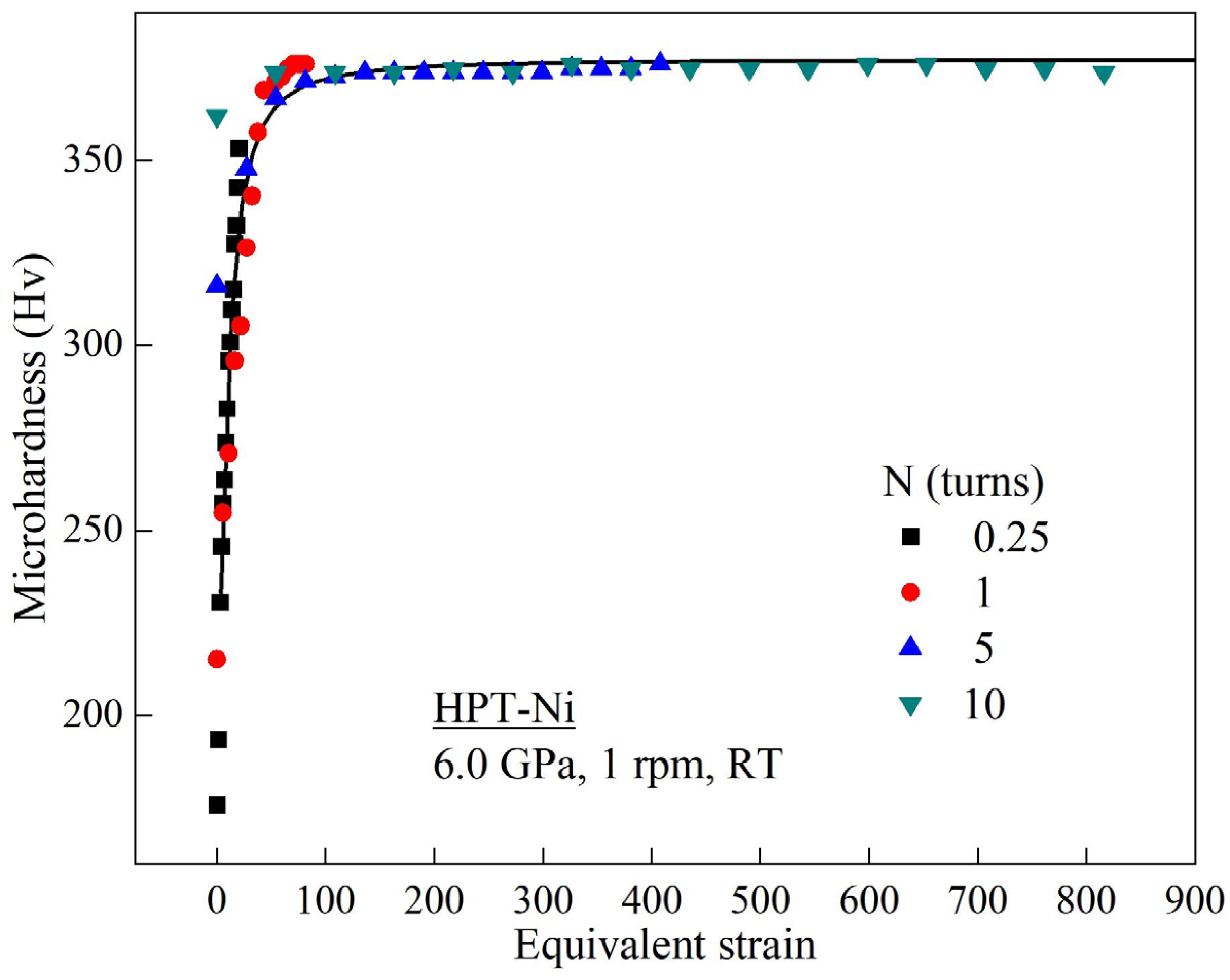
Independent of the number of revolutions, the HPT process results in negligible slip and thickness loss [31]. Under ideal conditions, the effect of axial compression on equivalent strain can be ignored when the sample diameter is much greater than the thickness. According to the HPT equivalent strain calculation equation [32]:
ε = 2 π N r 3 h = θ r 3 h
where N is the total number of turns, r is the distance from the disk’s center, and h is the thickness of the disk. For simplicity, the strain was calculated by maintaining the initial value of h in Equation (1); thus, the obtained values underestimated the actual deformation. Figure 10 depicts the relationship between the microhardness and the equivalent strain after varying numbers of turns. It can be seen that when the torsional strain is small, as the strain increases so the microhardness of the sample increases rapidly. However, when the torsional strain reaches 75, the microhardness of the sample increases very slowly to a saturation condition with the increase of strain. This law is consistent with the result of the SPD processing of samples. When the strain increases, the sample grain size increases; when the strain reaches a certain level, the sample grain size reaches a stable result. This conforms to the Hall–Petch relationship and the theory of fine-grain strengthening [33]. This is because as the number of HPT turns increases so the shear strain gradually increases, the dislocation density continues to increase, and the average grain size decreases sharply. The strengthening effect is very obvious. However, when the dislocation density reaches a certain critical value, dislocation recovery will significantly affect the further strengthening of the materials.

4. Discussion

4.1. Reasons for Development in HPT-Ni Microstructure

The present research shows that HPT is exceptionally excellent in producing very small grain sizes [19]. If the applied pressure is high and the number of turns is sufficient, the HPT processing can be used to develop a uniform and reasonable microstructure throughout the disks: In this experiment, at room temperature, it is found for pure Ni that a pressure of 6 GPa and more than five turns can achieve homogeneous grain refinement by HPT. It is worth noting that many of these enhanced properties are related to the increase in HAGBs. Therefore, the ideal UFG structure has excellent application potential. High-pressure torsion produces very large cold deformation, which makes the microstructure very significantly refined and finally produces UFG materials. Therefore, the microhardness increases. It is apparent that the edge has the highest hardness value in the disks, and also, the grain size is the smallest in this region. Hence, the dominant strengthening mechanism is grain boundary strengthening. In addition, the application of high pressure means that pure Ni can be treated with high pressure at room temperature without introducing any cracks in the disks, and the grain refinement process becomes more homogeneous.
According to Equation (1), the relationship between the equivalent strain and the distance r from the center of the specimen and the thickness h of the sample can be obtained. It can be seen that the distance r from the center of the sample is proportional to the equivalent strain. It is not difficult to find that at the same number of turns, the shear strain in the center region is smaller than that in the middle region and the edge, which is attributed to the shear strain gradient of the pure Ni disk. Because of this, the applied strain in the mid-radius region is greater than in the central region, leading to an earlier refined structure and the introduction of a non-uniform microstructure. Therefore, the degree of grain refinement and the proportion of HAGBs in the center of the sample are always smaller than the mid-radius and edge positions. Shear initially takes place at the edge, introducing local hardening. As a result, the shear is forced to transfer to an adjacent position and then slowly extends to the entire disk. When the number of turns is sufficiently high, it will be able to produce a homogeneous and reasonable UFG Ni structure. Even so, the central region of the disk cannot be refined to the same extent as the outer region.
When the radius is r = 0, the shear strain of the material processed by HPT is zero. That means there is no shear strain in the center of the specimen and no deformation in the center of the disks. However, the microstructure evolution shows that after HPT processing, the microstructure in the center of the sample gradually refines and becomes homogenous. This is because there is a strain gradient at the center of the sample. There are statistically stored dislocations and geometrically necessary dislocations in the material. As the number of turns increases, the density of geometrically necessary dislocations gradually increases, so the crystal grains in the center of the sample are gradually refined.

4.2. Analysis of HPT-Ni Grain Refinement Mechanism

There are numerous reports analyzing the grain refinement mechanism in SPD with an emphasis on HPT [34,35]. HPT processing uses the principle of plastic shear deformation of the material to refine the microstructure of the pure Ni sample. In this report, the microstructure evolution law of pure Ni during HPT is examined. According to the microstructure changes observed and the parameter values measured, a model was proposed to demonstrate the direct grain refinement method in HPT processing, as shown in Figure 11. The grain refinement process can be divided into four stages:
In the first stage, the original annealed structure is regular equiaxed grains, and the grains are relatively coarse. Because Ni has a face-centered cubic structure and has more independent slip systems, the material deforms by dislocation slip in the initial stage of plastic deformation. The main method is that dislocations accumulate at the grain boundaries, and a small amount of shear strain occurs.
In the second stage, dislocations interact and gather together to produce sub-grain boundaries in the coarse grains. The density of dislocations continues to increase. The dislocations are entangled in the grains and accumulate at the sub-grain boundaries.
In the third stage, as the deformation continues, the dislocations are absorbed by the sub-grain boundaries and converted into LAGBs. At this time, the sub-grain boundaries become clear, and their number increases. Furthermore, the differences in orientation between the sub-grains further increase.
In the fourth stage, the sub-grain size is reduced to form small grains so that the grain size continues to decrease and the difference in grain boundary orientations continues to increase. At this time, the dislocations generated by the shear deformation and the annihilated dislocations at the grain boundary reach equilibrium. It is the stable stage. This interpretation of grain refinement in HPT processing is consistent with the models developed using strain gradient plasticity [35].

5. Conclusions

This report examines an ideal UFG pure Ni material for plastic micro-forming through HPT processing. The microstructures and micro-hardness values of the material through various numbers of turns are studied. The main research results are as follows:
(1)
The microhardness measurement results show that the hardness values of Ni are symmetrical about the center of the sample, which in the central region is low and in the edge region is high. The hardness value gradually increases with an increase in the number of turns. Furthermore, each hardness value is directly related to the equivalent strain, so all points fall on or about one curve.
(2)
As shown in the EBSD measurements, the grain size gradually decreases, and the LAGBs are continuously transformed into HAGBs with an increase in the number of turns. The grain size and the fraction of HAGBs in the edge of the sample are smaller than the grain size at the center, which is due to the shear strain gradient of the sample.
(3)
As the number of HPT turns increases, the disk reaches a reasonable level of microstructure and hardness homogeneity, and its microstructure parameters and hardness value become saturated, indicating that strain processing parameters are very important for HPT processing.
(4)
It is concluded that the essence of HPT is the refinement of the microstructure caused by the shear strain, and a simple model of pure Ni grain refinement is proposed based on the evolution of the microstructure and grain boundary distribution.
(5)
The ultrafine-grained pure nickel materials processed using HPT processing have excellent mechanical properties and high cost-effectiveness in practical applications. Furthermore, applications involving mass production should be the focus of the development of this method and material. In order to efficiently prepare ultrafine pure nickel with large size, quick speed, and optimal microstructure, a more thorough investigation of the grain refinement mechanism is also being carried out at the same time. This material can also be used in other forming processes, such as current-aided microforming, to offer fresh approaches for minimizing size effects and other problems.

Author Contributions

Conceptualization, M.S., C.D. and J.X.; methodology, M.S., C.D. and J.X.; formal analysis, M.S., J.X., D.S., B.G. and T.G.L.; investigation, M.S. and C.D.; resources, J.X., D.S., B.G. and T.G.L.; data curation, M.S., C.D. and J.X.; writing—original draft preparation, M.S., C.D. and J.X.; writing—review and editing, J.X., D.S., B.G. and T.G.L.; visualization, M.S., C.D. and J.X.; supervision, J.X., D.S., B.G. and T.G.L.; project administration, J.X., D.S., B.G. and T.G.L.; funding acquisition, J.X., D.S., B.G. and T.G.L. All authors have read and agreed to the published version of the manuscript.

Funding

This research was funded by the National Natural Science Foundation of China, grant number No.51635005. The work of one of us was supported by the European Research Council under Grant Agreement No. 267464-SPDMETALS (TGL).

Data Availability Statement

Not applicable.

Conflicts of Interest

The authors declare no conflict of interest.

References

  1. Xu, J.; Wang, X.W.; Wang, C.J.; Yuan, L.; Chen, W.J.; Bao, J.X.; Su, Q.; Xu, Z.H.; Wang, C.J.; Wang, Z.L.; et al. A review on micro/nanoforming to fabricate 3D metallic structures. Adv. Mater. 2021, 33, 202000893. [Google Scholar] [CrossRef] [PubMed]
  2. Ovid’Ko, I.A.; Valiev, R.Z.; Zhu, Y.T. Review on superior strength and enhanced ductility of metallic nanomaterials. Prog. Mater. Sci. 2018, 94, 462–540. [Google Scholar] [CrossRef]
  3. Wang, Y.; Zhang, S.; Wu, R.Z.; Turakhodjaev, N.; Zhang, J.H.; Liu, M.D.; Mardonakulov, S. Concurrently improving uniform elongation and strength of ultrafine-grained Al-2Li alloy. Mater. Sci. Eng. A 2020, 792, 139848. [Google Scholar] [CrossRef]
  4. Langdon, T.G. Twenty-five years of ultrafine-grained materials: Achieving exceptional properties through grain refinement. Acta Mater. 2013, 61, 7035–7059. [Google Scholar] [CrossRef]
  5. Bach, J.; Stoiber, M.; Schindler, L.; Hoppel, H.W.; Goken, M. Deformation mechanisms and strain rate sensitivity of bimodal and ultrafine-grained copper. Acta Mater. 2020, 186, 363–373. [Google Scholar] [CrossRef]
  6. Shi, P.J.; Zhong, Y.; Li, Y.; Ren, W.L.; Zheng, T.X.; Shen, Z.; Yang, B.; Peng, J.C.; Hu, P.F.; Zhang, Y. Multistage work hardening assisted by multi-type twinning in ultrafine-grained heterostructural eutectic high-entropy alloys. Mater. Today 2020, 41, 62–71. [Google Scholar] [CrossRef]
  7. Zhilyaev, A.P.; Valiev, R.Z.; Langdon, T.G. Ultrafine-grained metallic materials and coatings. Adv. Eng. Mater. 2020, 22, 2001012. [Google Scholar] [CrossRef]
  8. Wu, Z.M.; Zhou, X.B.; Liu, J.W.; Du, J.L.; Zou, S.R.; Huang, Y.; Huang, Q.; Yang, K.J.; Zhang, J.; Huang, J.C. Ultrafine-grained W alloy prepared by spark plasma sintering with high thermal stability and excellent irradiation resistance. Nucl. Fusion 2020, 60, 036006. [Google Scholar] [CrossRef]
  9. Murzaev, R.T.; Bachurin, D.V.; Mukhametgalina, A.A.; Murzinova, M.A.; Nazarov, A.A. Ultrasonic treatment of ultrafine-grained titanium. Phys. Lett. A 2020, 384, 126906. [Google Scholar] [CrossRef]
  10. Orlowska, M.; Olejnik, L.; Campanella, D.; Buffa, G.; Morawinski, L.; Fratini, L.; Lewandowska, M. Application of linear friction welding for joining ultrafine grained aluminium. J. Manuf. Process 2020, 56, 540–549. [Google Scholar] [CrossRef]
  11. Vavra, T.; Minarik, P.; Vesely, J.; Kral, R. Excellent superplastic properties achieved in Mg-4Y-3RE alloy in high strain rate regime. Mater. Sci. Eng. A 2020, 784, 139314. [Google Scholar] [CrossRef]
  12. Komarasamy, M.; Wang, T.H.; Liu, K.M.; Reza-Nieto, L.; Mishra, R.S. Hierarchical multi-phase microstructural architecture for exceptional strength-ductility combination in a complex concentrated alloy via high-temperature severe plastic deformation. Scripta Mater. 2019, 162, 38–43. [Google Scholar] [CrossRef]
  13. Akensov, D.A.; Raab, G.I.; Asfandiyarov, R.N.; Semenov, V.I.; Shuster, L.S. Effect of Cd and SPD on structure, physical, mechanical, and operational properties of alloy of Cu-Cr-Zr. Rev. Adv. Mater. Sci. 2020, 59, 506–513. [Google Scholar]
  14. Xu, J.; Li, J.W.; Shan, D.B.; Guo, B. Strain softening mechanism at meso scale during micro-compression in an ultrafine-grained pure copper. AIP Adv. 2015, 5, 097147. [Google Scholar] [CrossRef]
  15. Xu, J.; Su, Q.; Shan, D.B.; Guo, B. Sustainable micro-manufacturing of superhydrophobic surface on ultrafine-grained pure aluminum substrate combining micro-embossing and surface modification. J. Clean. Prod. 2019, 232, 705–712. [Google Scholar] [CrossRef]
  16. Rosochowski, A.; Presz, W.; Olejnik, L.; Richert, M. Micro-extrusion of ultra-fine grained aluminium. Int. J. Adv. Manuf. Tech. 2007, 33, 137–146. [Google Scholar] [CrossRef]
  17. Durst, K.; Hofmann, S.; Backes, B.; Mueller, J.; Goken, M. Microimprinting of nanocrystalline metals—Influence of microstructure and work hardening. J. Mater. Process. Tech. 2010, 210, 1787–1793. [Google Scholar] [CrossRef]
  18. Mora-Sanchez, H.; Sabirov, I.; Monclus, M.A.; Matykina, E.; Molina-Aldareguia, J.M. Ultra-fine grained pure Titanium for biomedical applications. Mater. Technol. 2016, 31, 756–771. [Google Scholar] [CrossRef]
  19. Chen, W.; Xu, J.; Liu, D.; Bao, J.; Sabbaghianrad, S.; Shan, D.; Guo, B.; Langdon, T.G. Microstructural evolution and microhardness variations in pure titanium processed by high-pressure torsion. Adv. Eng. Mater. 2020, 22, 1901462. [Google Scholar] [CrossRef]
  20. Li, J.; Ding, C.; Chen, W.; Shan, D.; Guo, B.; Xu, J. Strain localization and ductile fracture mechanism of micro/mesoscale deformation in ultrafine-grained pure copper. Mater. Design 2023, 229, 111873. [Google Scholar] [CrossRef]
  21. Wang, Y.; Huang, P.; Liu, S.; Tayyebi, M.; Tayebi, M. Microstructural evolution, shielding effectiveness, and the ballistic response of Mg/Al7075/B4C/Pb composite produced by combination of coating and severe plastic deformation (SPD) processes. J. Manuf. Process 2022, 84, 977–985. [Google Scholar] [CrossRef]
  22. Zhilyaev, A.P.; Langdon, T.G. Using high-pressure torsion for metal processing: Fundamentals and applications. Prog. Mater. Sci. 2008, 53, 893–979. [Google Scholar] [CrossRef]
  23. Azzeddine, H.; Bradai, D.; Baudin, T.; Langdon, T.G. Texture evolution in high-pressure torsion processing. Prog. Mater. Sci. 2022, 125, 100886. [Google Scholar] [CrossRef]
  24. Ding, C.; Chen, W.; Sabbaghianrad, S.; Xu, J.; Shan, D.; Guo, B.; Langdon, T.G. In situ TEM observations of thickness effect on grain growth in pure titanium thin films. Mater. Charact. 2021, 173, 110929. [Google Scholar] [CrossRef]
  25. Ma, M.; Ding, H.; Huang, Y.; Tian, C.W.; Langdon, T.G. Microstructural and hardness evolution in a duplex stainless steel processed by high-pressure torsion. Crystals 2020, 10, 1138. [Google Scholar] [CrossRef]
  26. Horita, Z.; Smith, D.J.; Furukawa, M.; Nemoto, M.; Valiev, R.Z.; Langdon, T.G. An investigation of grain boundaries in submicrometer-grained Al-Mg solid solution alloys using high-resolution electron microscopy. J. Mater. Res. 1996, 11, 1880–1890. [Google Scholar] [CrossRef]
  27. Iwahashi, Y.; Horita, Z.; Nemoto, M.; Langdon, T.G. Factors influencing the equilibrium grain size in equal-channel angular pressing: Role of Mg additions to aluminum. Metall Mater Trans A 1998, 29, 2503–2510. [Google Scholar] [CrossRef]
  28. Wongsa-Ngam, J.; Kawasaki, M.; Langdon, T.G. A comparison of microstructures and mechanical properties in a Cu–Zr alloy processed using different SPD techniques. J. Mater. Sci. 2013, 48, 4653–4660. [Google Scholar] [CrossRef]
  29. Figueiredo, R.B.; Pereira, P.; Aguilar, M.; Cetlin, P.R.; Langdon, T.G. Using finite element modeling to examine the temperature distribution in quasi-constrained high-pressure torsion. Acta Mater. 2012, 60, 3190–3198. [Google Scholar] [CrossRef]
  30. Xu, J.; Li, J.; Wang, C.T.; Shan, D.; Guo, B.; Langdon, T.G. Evidence for an early softening behavior in pure copper processed by high-pressure torsion. J. Mater. Sci. 2016, 51, 1923–1930. [Google Scholar] [CrossRef]
  31. Edalati, K.; Yamamoto, A.; Horita, Z.; Ishihara, T. High-pressure torsion of pure magnesium: Evolution of mechanical properties, microstructures and hydrogen storage capacity with equivalent strain. Scripta Mater. 2011, 64, 880–883. [Google Scholar] [CrossRef]
  32. Valiev, R.Z.; Ivanisenko, Y.V.; Rauch, E.F.; Baudelet, B. Structure and deformaton behaviour of Armco iron subjected to severe plastic deformation. Acta Mater. 1996, 44, 4705–4712. [Google Scholar] [CrossRef]
  33. Figueiredo, R.B.; Kawasaki, M.; Langdon, T.G. Seventy years of Hall-Petch, ninety years of superplasticity and a generalized approach to the effect of grain size on flow stress. Prog. Mater. Sci. 2023, 137, 101131. [Google Scholar] [CrossRef]
  34. Luo, J.; Yu, W.; Xi, C.; Zhang, C.; Ma, C. Preparation of ultrafine-grained GH4169 superalloy by high-pressure torsion and analysis of grain refinement mechanism. J. Alloy. Compd. 2019, 777, 157–164. [Google Scholar] [CrossRef]
  35. Estrin, Y.; Molotnikov, A.; Davies, C.H.J.; Lapovok, R. Strain gradient plasticity modelling of high-pressure torsion. J. Mech. Phys. Solids 2008, 56, 1186–1202. [Google Scholar] [CrossRef]
Figure 1. HPT processing: (a) Microstructure of pure Ni annealed; (b) HPT device; (c) Samples of different turns processed by HPT.
Crystals 13 00887 g001
Figure 2. Values of the Vickers microhardness versus distance from the centers of the disks after HPT processing at a pressure of 6.0 GPa for various numbers of turns.
Crystals 13 00887 g002
Figure 3. Color-coded contour maps showing the Vickers microhardness of the 1/4 area of disks processed by HPT through (a) 1/4; (b) 1; (c) 5; (d) 10 turns.
Crystals 13 00887 g003
Figure 4. Microstructures of pure Ni processed by HPT through (a) 1/4; (b) 1; (c) 5; (d) 10 turns at the center position.
Crystals 13 00887 g004
Figure 5. Microstructures of pure Ni processed by HPT through (a) 1/4; (b) 1; (c) 5; (d) 10 turns at the mid-radius position.
Crystals 13 00887 g005
Figure 6. Microstructures of pure Ni processed by HPT through (a) 1/4; (b) 1; (c) 5; (d) 10 turns at the edge position.
Crystals 13 00887 g006
Figure 7. Histograms of the misorientation angles at the center of the samples processed by HPT for (a) 1/4, (b) 1, (c) 5, and (d) 10 turns: the individual fractions of low-angle and high-angle boundaries are indicated.
Crystals 13 00887 g007
Figure 8. Histograms of the misorientation angles at the mid-radius position corresponding to 2.5 mm from the center of the samples processed by HPT for (a) 1/4, (b) 1, (c) 5, and (d) 10 turns: the individual fractions of low-angle and high-angle boundaries are indicated.
Crystals 13 00887 g008
Figure 9. Histograms of the misorientation angles at the edge of the samples processed by HPT for (a) 1/4, (b) 1, (c) 5, and (d) 10 turns: the individual fractions of low-angle and high-angle boundaries are indicated.
Crystals 13 00887 g009
Figure 10. Microhardness plotted against equivalent strain after processing by HPT.
Crystals 13 00887 g010
Figure 11. Pure nickel grain refinement model during HPT processing: (a) Phase 1; (b) Phase 2; (c) Phase 3; (d) Phase 4.
Crystals 13 00887 g011
Table 1. Summary of HPT processing of Pure Ni.
MaterialHPT ProcessingAnnealing ConditionsGrain Size
Dimensions D × h/mmTPressure/GPaRotation Rate/rpmN/TurnsT/°Ct/minFinal/µm
Pure Ni10 × 0.82RT6.011/4, 1, 5, 107001200.21–1.42
Table 2. Microstructure parameters of HPT-Ni.
Specimen1/4 t1 t
CenterInterEdgeCenterInterEdge
Grain size (µm)1.420.810.530.590.390.26
Specimen5 t10 t
CenterInterEdgeCenterInterEdge
Grain size (µm)0.350.230.220.330.220.21
Disclaimer/Publisher’s Note: The statements, opinions and data contained in all publications are solely those of the individual author(s) and contributor(s) and not of MDPI and/or the editor(s). MDPI and/or the editor(s) disclaim responsibility for any injury to people or property resulting from any ideas, methods, instructions or products referred to in the content.