Abstract
Semiconductor ionic electrolytes, especially heterostructure composites, have a significant role in enhancing oxide ion conductivity and peak power density (PPD) because of their interfacial contact. In this work, the fluorite structure CeO2 and spinel-based CoAl2O4 samples, as a heterostructure composite electrolyte, are successfully fabricated. The p-type CoAl2O4 and n-type CeO2 heterostructure (CeO2-CoAl2O4) used as an electrolyte exhibits a cell performance of 758 mW/cm2 under fuel cell H2/air conditions at 550 °C, which is quite higher than the pure CoAl2O4 and CeO2 fuel cell devices. Scanning electron microscopy (SEM) and high-resolution transmission electron microscopy (HR-TEM) verified the heterostructure formation including the morphological analysis of the prepared heterostructure composite. The heterostructure-based CeO2-CoAl2O4 composite achieved a higher ionic conductivity of 0.13 S/cm at 550 °C temperature, which means that the constructed device successfully works as an electrolyte by suppressing electronic conductivity. Meanwhile, the obtained results demonstrate the semiconductor ionic heterostructure effect by adjusting the appropriate composition to build heterostructure of the n-type (CeO2) and p-type (CoAl2O4) components and built-in electric field. So, this work exhibits that the constructed device can be effective for energy conversion and storage devices.
1. Introduction
Since the 19th century, energy conversion and storage devices have attracted extensive attention because of their feasible conversion efficiency and environmental benefits [1]. Basically, SOFCs are conversion devices that directly convert chemical energy into electricity with the multi-benefits of higher conversion efficiency, multi-fuel flexibility, no pollutants, and ecological friendliness [2,3,4]. According to traditional knowledge, the electrolyte is the core and crucial component in realizing ionic transport, such as YSZ (Yttria-stabilized zirconia), which needs a high operational temperature of above 800 °C to reach high oxide ion conductivity and better cell performance. Unfortunately, the higher operating temperature (>800 °C) induces problems with the selection of materials, cost, quick start-up and shut-down cycles, and degradation of OCV and cell performance [5,6,7,8]. Therefore, many efforts are deployed to design new electrolytes to enable the device to deliver high ionic conductivity (>0.1 S/cm) operating at low operational temperatures (<600 °C) to be commercially valuable following the statement of Goodenough [9,10,11]. Still, substituting new electrolytes to maintain high peak power density at low operating temperatures is inevitable. So, to overcome these bottlenecks, various novel techniques are being used, such as thin film that can reduce the thickness (lower ohmic and polarization resistance) and deliver high performance at low temperatures but still has some key challenges of a higher cost of manufacture, slow rate of production, and scaling up micro-SOFCs [6,12,13,14,15,16].
From the other perspective, recently, plenty of research has been diverted to the use of perovskite (BaCo0.4Fe0.4Zr0.1Y0.1O3, SrFe0.2Ti0.8O3), fluorite (Sm0.2Ce0.8O2), and spinel CoGd0.2Fe1.8O4 (CGFO) structure-based electrolytes and electrodes to enhance the electrical characteristics, mainly conductivity and performance [17,18,19,20,21]. Mostly, the researchers used the idea of constructing a semiconductor heterostructure electrolyte to improve the peak power output of constructed devices and higher ionic conductivity [22]. Zhu et al. proposed the concept of preparing a composite heterostructure constituting a built-in electric field (BIEF) to enhance the fuel cell performance at a low operating temperature of 300–600 °C [23]. Furthermore, Mushtaq and Shah et al. have designed SFT-based composite electrolytes, including semiconductor ionic (SFT-SDC) and p-n (SFT-ZnO) heterostructure electrolytes, delivering impressive peak power outputs of 920 mW/cm2 and 650 mW/cm2 at 520 °C. The semiconductor heterojunction formation constitutes the BIEF (built-in electric field), enhancing the power density and oxide ion conductivity of 0.12 and 0.21 S/cm by suppressing the electronic conductivity and preventing the fabricated device from short circuits [24,25].
Similarly, Xia et al. have demonstrated a novel composite heterostructure electrolyte by combining the triple conducting perovskite oxide BCFZY (BaCo0.4Fe0.4Zr0.1Y0.1O3) and hexagonal structure ZnO to build the p-n heterojunction (BCFZY-ZnO). The built heterojunction has delivered higher ionic conduction and high-power density of 643 mW/cm2 and reduced electronic conduction [20]. Moreover, many single-phase semiconductors, LixAl0.5Co0.5O2, SmNiO3, and SrFe0.2Ti0.8O3, have been designed to deliver feasible peak power output at 550 °C under H2/air conditions [26,27].
Many Co-based oxides have been reported as an electrolyte membrane and include the feasible peak power output. For example, Co-doped SrSnO3 and SrCo0.3Sn0.7O3-CeO2 are used as electrolytes and reported good fuel cell performance and high oxide ion conductivity at 520 °C [28,29]. In addition, Co-based spinel structures such as CoAl2O4 have been used to apply OER catalysts via optimizing the electronic structure to achieve the tunable reconstruction of electrochemicals [30]. To our knowledge, CoAl2O4 has not yet been used for applying SOFC, and the construction of heterostructure and facilitation of charge redistribution at the interface has remained elusive.
In this regard, we have used the approach of constructing a heterostructure of different structures such as spinel and fluorite structures (CoAl2O4-CeO2) using the solid blending technique. The designed heterostructure (p-CoAl2O4 and n-CeO2 semiconductor) has shown competent electrolyte functionalities. The developed heterostructure has displayed impressive results of higher peak power output and exceptional oxide ion conduction, realizing better functionality of the p-n junction as an electrolyte. Meanwhile, the formation of heterojunction and energy band alignment with BIEF helps to suppress the electronic conduction and promote ionic conductivity. The attained results and characterization reveal the effective demonstration of p-n heterojunction and pave the way to develop a novel semiconductor ionic electrolyte for advanced low-temperature SOFCs.
2. Materials and Methods
2.1. Material Synthesis
The CoAl2O4 sample was successfully prepared using the sol-gel auto-combustion method. Co(NO3)2·6H2O (99.1%, Aladdin, Shanghai China), Al(NO3)3·9H2O (99.95%, Sigma Aldric, Burlington, MA, USA), were individually dissolved with 0.01 molar ratio into a 250 mL deionized (DI) water and then constantly stirred for 6 h. In the next step, both solutions were mixed and stirred using a magnetic stirrer on a hot plate for 6 h. Additionally, the homogenous solution was constantly stirred as well as heated until the solution changed into the gel form. Ammonia solution was dropwise added into the final solution to control pH~7. The magnetic stirrer hot plate temperature was risen from room temperature to 75 °C by following the sol-gel method. The gel of the formed CoAl2O4 sample was ignited at 110 °C temperature to follow auto-combustion approach. The resulting gray ashes were grounded well and put into the muffle furnace for calcination. The muffle furnace temperature was set around 850 °C for 5 h with 5°/min range. The obtained particles were grounded well and then sent for further assessments. For ceria, the Ce(NO3)3·9H2O (99.95%, Sigma Aldric) was used as a precursor and added into the 500 mL DI water with continuous stirring, and Sodium carbonate anhydrous was used and mixed into the ceria solution as a precipitating agent with 1:1 mole ratio. The resulting powder was filtered and dried in a heating oven for 12 h at 150 °C. The obtained powder was ground and sintered in a muffle furnace for 4 h at 800 °C with 5°/min temperature range. Moreover, the composite of CoAl2O4 with CeO2 with 2:8 weight ratio was prepared using ball milling technique at 400 rpm speed for 12 h and followed by heat treatment for 4 h at 600 °C temperature.
2.2. Cell Preparation
The commercially purchased Ni0.8Co0.15Al0.5LiOx (NCAL, Tianjin Bamo Sci.&Tech. Joint Stock Ltd., Tianjin, China) was used as an electrode. The specific amount of NCAL powder was weighed and mixed with terpineol to make slurry gel and then the prepared slurry gel was painted on 2.0 mm Nickel foam (Ni-Foam) to make an electrode. The fabricated electrodes were heated at 130 °C for 30 min for drying purposes. The prepared heterostructure of CeO2-CoAl2O4 was used as an electrolyte membrane with Ni-NCAL electrodes with the configuration of Ni-NCAL/CeO2-CoAl2O4/Ni-NCAL and electrolyte powder was pressed between two electrodes under the 250 MPa to construct fuel cell device. The fabricated fuel cell device, with a 13 mm diameter, was used for electrochemical measurements. The thickness of the cell was 1.5 mm while the thickness of electrolyte layer was 750 µm. Additionally, the constructed device was also employed to examine I-V and I-P characteristics. H2 was used as fuel with 90–110 mL min−1 flow rate and the air was used as an oxidant with a flow rate of 130–150 mL min−1.
2.3. Characterizations
The phase analysis of CoAl2O4 and CeO2 powder was identified via X-ray diffraction (XRD) using Cu Kα1 radiation with λ = 0.1548 nm wavelength with 40 kV working voltage under the scanning range of 10–80° and scanning speed was set around 5°min−1. Scanning electron microscopy (SEM) and high-resolution transmission electron microscopy (TEM, JEOL JEM-2100F, Tokyo, Japan) were used to analyze the morphology, grains, grain size, and porosity effects of synthesized CoAl2O4, CeO2, CeO2-CoAl2O4 samples. UV-Vis spectroscopy was used to study the semiconducting nature of the synthesized samples. For electrochemical study, EIS measurements were done using Gamry Reference 3000 (Gamry Instruments, Louis Drive Warminster, PA, USA) at different elevated temperatures under H2/air conditions. The I-V and I-P characteristics of constructed fuel cell devices were measured by electronic load instrument (IT8511, ITECH Electrical Co., Ltd., Shanghai, China) under H2/air.
3. Results
3.1. Structural and Morphological Analysis
X-ray diffraction of CoAl2O4, CeO2, and CeO2-CoAl2O4 (CAO) was employed to analyze the structural behavior, i.e., single-phase nature for individual CoAl2O4 and CeO2 and heterostructure formation of CeO2-CoAl2O4. The CoAl2O4, CeO2, and CeO2-CoAl2O4 XRD patterns are presented in Figure 1. The diffraction peaks of CoAl2O4 correspond to JCPDS card # 01-078-1603. It can be observed from the XRD pattern that CoAl2O4 and CeO2 powder has a single-phase cubic nature with spinel and fluorite structure, respectively. While a clear heterostructure can be noticed in the CeO2-CoAl2O4 sample without observing any extra peak. No extra peaks in the heterostructure sample were observed which verifies the successful formation of a heterostructure between CeO2 and CoAl2O4. The miller indices with the JCPDS card # 01-088-1943 are associated with the CeO2 sample and high-intensity peak of (1 1 1), and are well matched with the reported ceria literature [31]. The average cubic crystallite size was calculated for CeO2 using the (1 1 1) plane and for CoAl2O4 using the (3 1 1) plane using the following relations:
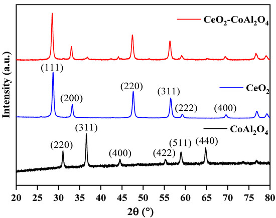
Figure 1.
XRD patterns: pure CoAl2O4, pure CeO2, and CeO2-CoAl2O4 heterostructures.
The average crystallite size of the CoAl2O4, CeO2 sample is 24.01, 20.43 nm, and the heterostructure base sample crystallite size is 21.48 nm. The increase in crystallite size is because of the addition of rare earth oxides as a heterostructure in the CeO2-CoAl2O4 sample. Additionally, during the formation of the composite, some atoms of Ce with higher ionic radii could be replaced with Co or Al site of the CoAl2O4 with a lower ionic radius. However, the crystallite size of the heterostructure was observed as higher.
The scanning electron microscopy (SEM) images of CoAl2O4 and CeO2-CoAl2O4 are shown in Figure 2a,b. The smaller particles with homogenous grains can be observed in the CoAl2O4 sample, which means that sol-gel auto combustion is a feasible approach for nanoparticle formation. Smaller and larger grains were observed in the CoAl2O4 sample and compact grains can be noticed in CeO2-CoAl2O4, see Figure 2a,b. The compact grains and large agglomerations in the heterostructure sample are feasible as an electrolyte membrane for SOFC applications. Moreover, the grain size of the synthesized samples is measured using the line intercept method. The grain size of CoAl2O4, and CeO2-CoAl2O4 samples are in the 65–90 and 50–65 nm range, confirming the formation of nanoparticles. Additionally, high-resolution transmission electron microscopy (HR-TEM) was used to study the grain size and its distribution, compact grains, and agglomerations of the prepared CeO2-CoAl2O4 samples. Figure 2c shows the HR-TEM images of the CeO2-CoAl2O4 sample. The similar fine nanoparticles in the CoAl2O4 sample may also verify our SEM image, while larger agglomerations with the addition of CeO2 in CoAl2O4 as a heterostructure composite can be observed in Figure 2c. Moreover, the lattice fringes of the CeO2-CoAl2O4 sample were examined by digital micrography (DM) software. Figure 2d exhibits the lattice plane fringes of the CeO2 and CoAl2O4 samples, which means the successful formation of a heterostructure composite. The lattice fringes with distances of 0.321 nm and 0.271 nm are linked with the (1 1 1) and (2 0 0) lattice planes of fluorite structure (CeO2), while 0.369 nm fringes are linked with the (3 1 1) plane of the spinel structure (CoAl2O4). Figure 2d exhibits the higher intensity (3 1 1) peak lattice fringes of the CoAl2O4 sample, which is evidence of the formation of the single-phase cubic spinel structure [30]. Moreover, to examine the homogeneous distribution of synthesized grains in the composite CeO2-CoAl2O4 sample, HR-TEM elemental mapping embedded with EDS was carried out and the results are presented in Figure 3a–e. The elemental mapping and EDS further verify the chosen precursors as well as the similar distribution of Co, Al, Ce, and O elements. The homogeneous distribution exhibits that the chosen elements are arranged well throughout the synthesizing process. The uniformity in particle distribution enhances the interfacial conduction, which may cause the improvement in the oxide ion conductivity of the CeO2-CoAl2O4 nanocomposite, resulting in fast ion mobilities [20,24,25].
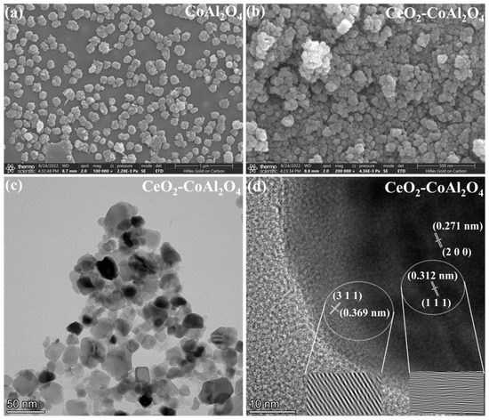
Figure 2.
(a,b) Scanning electron microscopy (SEM) images of CoAl2O4 and CeO2-CoAl2O4, and (c,d) high-resolution transmission electron microscopy (HR-TEM) images, CeO2-CoAl2O4 sample.
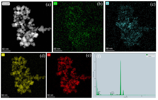
Figure 3.
(a–f) The elemental mapping and EDS analysis of CeO2-CoAl2O4 sample using HR-TEM.
3.2. XPS Analysis
To further access the surface and interface properties of the prepared sample, XPS was performed. Figure 4a shows the XPS survey spectra of pure CeO2, CoAl2O4, and CoAl2O4-CeO2. The XPS measurements for CeO2-CoAl2O4 are characterized by the existence of characteristic peaks Co, Al, Ce, and O, while pure CeO2 shows Ce and O. CoAl2O4 is distinguished by Co, Al, and O. The distinguishing characteristic peaks in the sample without any further addition suggest no impurities or chemical changes while synthesizing and bleeding the powder. Furthermore, by using Gaussian functions chemical states, O1s spectra were deconvoluted to probe the surface properties, as shown in Figure 4b–d. Oxygen spectra were deconvoluted into lattice oxygen (Oα), having a binding energy of 528.5–530, and surface oxygen defects (Oδ) with a binding energy of 530–531.5. O1s spectra peaks with the binding energy 531–532.5 can be assigned to Chemisorbed oxygen species (Oβ) [32]. Moreover, to further investigate the distribution of all three different O1s peaks, Thermo Avantage digital software was used. From the calculations, it was found that in pure CeO2 the relative atomic ratio of (Oδ + Oβ)/Oα is 0.3/0.7, while on adding CoAl2O4 the relative atomic ratio increased to 0.45/0.55 depicting 15% increments in surface oxygen vacancies. These results show the combining of CoAl2O4 and CeO2 enriched oxygen vacancies as a result of atomic reconstruction caused by a dissimilar lattice mismatch, which creates more oxygen vacancies, and, subsequently, will increase the ionic conductivity [33]. The Chemisorbed oxygen species presence helps in enhancing oxygen vacancies, and as a result the CeO2-CoAl2O4 heterostructure gains significantly high ionic conductivity.
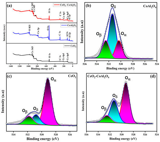
Figure 4.
(a–d) XPS survey spectra and O1s spectra of CoAl2O4, CeO2, CeO2-CoAl2O4 samples.
3.3. Electrochemical Analysis
To further analyze the electrochemical performance of pure CoAl2O4, pure CeO2, and CeO2-CoAl2O4 composite, EIS was performed at different temperatures of 550–450 °C under H2/air conditions. The fabricated devices were operated under an open circuit voltage condition (where OCV is the voltage of the cell in a steady state). Figure 5a,b shows the I-V and I-P characteristics of fabricated fuel cell devices under H2/air conditions. The CoAl2O4 sample delivers a PPD of 142 mW/cm2, pure CeO2 exhibits a PPD of 420 mW/cm2 at 550 °C, and the PPD of 758 mW/cm2 of the CeO2-CoAl2O4 composite was observed at 550 °C under H2/air. The obtained high PPD performance of CeO2-CoAl2O4 is comparable with the results of state-of-the-art SOFC electrolytes using pure CeO2 as an electrolyte membrane, which means that by constructing heterostructures between CeO2 and CoAl2O4, this may cause enhanced oxide ion conductivity resulting in higher fuel cell performance. The higher PPD in CeO2-CoAl2O4 can be ascribed to the enhanced oxide ion conductivity as well as defects produced between the two different fluorite and spinel structures. The structural deformation at the interface because of the weaker lattice provides a channel for fast oxide ion transportation. The weaker bonds at the interface are enriched with oxygen defects, which were also verified by the XPS O1s spectra of the CeO2-CoAl2O4 sample that may also cause enhanced oxygen vacancies as a result of ion mobility at the interface. Including high PPD, the fabricated fuel cell devices also demonstrate a higher OCV of >1.00 V, even at a low 450 °C temperature; moreover, this verifies that the constructed fuel cell device has the potential to maintain a voltage over 1.00 V even at low temperatures. With higher Power, the prepared composite cathode CeO2-CoAl2O4 also demonstrates high OCVs above 1.00 V, even at a low temperature of 470 °C, certifying that the constructed electrolyte has the potential to maintain OCVs at low operating temperatures.
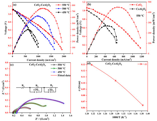
Figure 5.
(a) I-V and I-P characteristics of CeO2-CoAl2O4 fuel cell devices, (b) I-V and I-P characteristics of CeO2 and CoAl2O4 fuel cell devices, (c) EIS analysis of CeO2-CoAl2O4 fuel cell device, (d) Ionic conductivity analysis of CeO2-CoAl2O4 fabricated device.
The EIS of the CeO2-CoAl2O4 fabricated device was analyzed from 450 °C to 550 °C under H2/air conditions and presented in Figure 5c. Normally, three semicircles are observed regarding SOFC-fabricated fuel cell devices and similar behavior has been observed in our work. Firstly, the small semicircle at a higher frequency is accredited to the bulk material behavior (ohmic resistance), such as the chosen CeO2-CoAl2O4 electrolyte material, and the second arc at an intermediate frequency region is ascribed to grain boundary resistance. The third semicircle, which can be seen in a low-frequency region, is due to the porous electrode polarization resistance [34]. Chen Xia et al. [35] explained in detail the semicircle behavior at different frequencies under H2 and air at elevated temperatures. It can be observed that the ohmic resistance of the CeO2-CoAl2O4 fabricated device is comparable to the reported literature [36,37]. The measured impedance spectra of the prepared electrolyte layer are fitted using the equivalent circuit, as mentioned in Figure 5c, in which Ro, R1, and R2 are ohmic resistance, R1 and R2 are the electrode resistance and Q is the constant phase element (CPE). The measure of ohmic resistance of the CeO2-CoAl2O4 fuel cell device was in the range of 0.185 Ω·cm2 at 550 °C fuel cell operational temperature. The measured polarization resistance (Rp) of the fabricated device decreased from 0.416 Ω·cm2 at 550 °C under fuel cell conditions.
This enriched CeO2-CoAl2O4 provides a channel for ionic conduction, resulting in higher PPD than pure CeO2 and CoAl2O4 samples. Because of the dominant role of oxide ion conduction, the ionic conductivity of the CeO2-CoAl2O4 fuel cell device was evaluated using the liner part of the polarization curve method, as reported in SOFC literature [18]. The linear part of the I-V curve at a low intermediated region represents the total ohmic losses of the fabricated fuel cell device, which can be denoted by the ohmic resistance of electrolyte and electrodes. In the work, the ohmic resistance was obtained from the linear part of the polarization curve and the ionic conductivity of the CeO2-CoAl2O4 sample was calculated using the following relation , while calculated ionic conductivity values of the CeO2-CoAl2O4 fuel cell device are presented in Figure 5d. From the calculated data, the CeO2-CoAl2O4 heterostructure sample ionic conductivity values are 0.131 S cm−1 to 0.065 S cm−1 at 550–450 °C, which is feasible and comparable to the SOFC reported in the literature [28]. These heterostructure-based results can be elaborated to the effect of interfacial ionic conduction with two aspects; one of them is the CeO2-CoAl2O4 bulk-heterostructure, which provides a fast transport oxide ions channel at the interface, resulting in improving ionic conductivity as compared to pure CoAl2O4 and CeO2 that may also cause an enhancement in fuel cell performance above pure samples. The second reason is to choose the optimal ratio of CeO2 and CoAl2O4, which will further lead to different amounts and distribution of the hetero interface in these samples to promote oxide ion conductivity. In our case, different optimal ratios of CeO2 and CoAl2O4 samples have been chosen and the best one with an 8:2 ratio was reported because of its feasible ionic conductivity and higher fuel cell performance. Therefore, we may conclude that, at the 8:2 optimal ratio, CeO2 and CoAl2O4 grains are perfectly matched and homogenously distributed to form a sufficient heterostructure-based interface for oxides on conduction as well as better fuel cell performances.
For ionic conductivity analysis using EIS, the complex impedance spectra of the cell Pt|CeO2-CoAl2O4|Pt were evaluated under similar air and 5% H2/Ar conditions at 450–550 °C. Figure 6a–c exhibits the complex impedance spectra of the cell with configurations of Pt|CeO2-CoAl2O4|Pt and the first intercept on the X axis in the high-frequency region denotes the ohmic resistance (Ro) of the materials. To evaluate the ionic conductivity, it was found that the ohmic resistance (Ro) represents the electrolyte, as discussed in the literature. Moreover, the equivalent circuit of (R1CPE1) (R2CPE2) was used to analyze the experimental data. In the equivalent circuit, Ro denotes the ohmic resistance, while CPE is the constant phase element demonstrating a nonideal capacitor, and R1 and R2 represent the electrode polarization resistance. The ionic conductivity of CeO2-CoAl2O4 is calculated using the following relationship;
where L is the thickness of the sample (890 µm), A is the area of the cell (0.64 cm2), and Ro is ohmic. So, the value of half-cell Pt|CeO2-CoAl2O4|Pt is 0.086 S·cm−1 in air and 0.043 S·cm−1 at 550 °C, which shows that the ionic conductivity of CeO2-CoAl2O4 can be improved in an H2-rich atmosphere. It means the protonic conductivity could be dominant in CeO2-CoAl2O4 materials. Moreover, for the post-investigation analysis of the cell, the cross-sectional SEM was done and the obtained image is presented in Figure 6d, which shows no obvious cracks after the fuel cell performance of the cell. However, the CeO2-CoAl2O4 shows good chemical compatibility with the NCAL electrode, which could guarantee good fuel performance for long time operation.
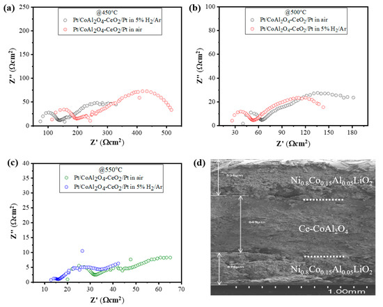
Figure 6.
(a–c) EIS analysis of CeO2-CoAl2O4 in configuration of Pt/CeO2-CoAl2O4/Pt in air and 5% H2/95%Ar at 450 °C–550 °C and (d) the cross-sectional SEM image of fuel cell with configurations of Ni0.80Co0.15Al0.05LiO2/CeO2-CoAl2O4/Ni0.80Co0.15Al0.05LiO2 after fuel cell performance measurements.
3.4. Optical Analysis
An optical study is an important key to analyzing the semiconducting nature of the prepared samples. For this reason, CoAl2O4 and CeO2 samples were tested by UV-Vis spectroscopy to evaluate optical bandgap. The optical bandgap of pure CoAl2O4 and CeO2 samples and Vb values are presented in Figure 7a–d. Moreover, the optical bandgap of the prepared samples was calculated using the relation as given below [38]:
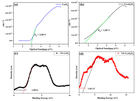
Figure 7.
(a,b) Optical bandgap of CeO2 and CoAl2O4, (c,d) Vb maxima of synthesized CeO2 and CoAl2O4 samples.
Figure 6a,b exhibits the bandgap values of CoAl2O4 and CeO2 samples that were tested by UV-Vis spectroscopy to evaluate optical bandgap, which exhibits the measured bandgap of the pure CoAl2O4 and CeO2 samples. Moreover, the optical bandgap of the CoAl2O4 and CeO2 samples was in a range of 2.90 eV and 1.85 eV, respectively. The measured bandgap (Eg) of the prepared CoAl2O4 exhibits a semiconducting nature.
Since the discovery of semiconductor-based fuel cells, electronic conduction always seems to be unfavorable, which strictly follows the concept of traditional knowledge of zero electronic conduction in the electrolyte layer to realize the fuel cell operation. However, our approach of heterojunction CeO2-CoAl2O4 revealed better cell performance and feasible oxide ion conductivity with higher OCV under low operational temperatures, which may be because of the incorporation of P-type CoAl2O4 into the n-type semiconductor CeO2 to attain the composite heterostructure as confirmed by the HR-TEM images of the formation of the composite heterostructure. Two different materials with different charge characteristics combine to build a p-n junction at the particle levels due to unbalanced charge distribution at the interface. Furthermore, charge redistribution at the interface establishes a space charge region that further creates a built-in electric field (BIEF), consequently excelling the ions transportation and suppressing the electronic conduction in the proposed heterojunction of CeO2-CoAl2O4 [20,25,29,39]. To construct the heterojunction, energy bandgap and valence band position were evaluated using the UV-Vis (Kubelka—Munk function) and XPS Vb spectra, as depicted below. The bandgap of 3.2 and 2.4 eV and the position of the valence bands of 6.5 and 7.3 eV correspond to the CeO2 and CoAl2O4, respectively. Furthermore, the Conduction band value was determined using the following equation Vb = Vc + Eg, giving the values of 1 eV and 0.4 eV. These values verify the existence of the p-n heterojunction at the particle level, and the junction mechanism with the fuel cell diagram is shown in Figure 8a,b. Additionally, the response current measurement of the fabricated device p-n junction device under a bias voltage was also performed to analyze the p-n junction mechanism in the fabricated device. In Figure 8c, the p-n junction-based SOFC has a diode rectification characteristic under DC bias voltage, exhibiting the formation of the built-in electric field in the constructed interfaces. The rectification response of the p-n junction CeO2-CoAl2O4 device is apparently stronger and the recorded current is also much lower values, which is feasible for the heterostructure electrolyte design, as discussed in the literature. The response current under negative applied voltage can notify that the constructed heterojunction can block electrons. So, the p-n junction application with the Al doping as well as taking part in the heterostructure base CeO2-CoAl2O4 sample may significantly strengthen the electron blockage capability of electrolyte-based components and exhibits a more effective space charge region. The CoAl2O4 plays an important role because of its ultrawide bandgap as well as insulating properties. Therefore, a distinct energy band structure and interfacial contact is formed in the CeO2-CoAl2O4 SOFC device, resulting in enhancing oxide ion conductivity.
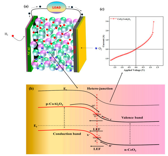
Figure 8.
(a,b) The schematic diagram of fuel cell based on CeO2-CoAl2O4 electrolyte and illustration of p-n junction mechanism in CeO2-CoAl2O4. (c) Ag/CeO2-CoAl2O4/Ag layered structure under N2 gas atmosphere at 550 °C.
Moreover, in some extensive previous practice, using Lithium-containing NCAL electrodes in ceramic fuel cells exhibit much better electrochemical performance at a lower temperature range of 450 to 550 °C. In reality, NCAL at the anode side is reduced by H2 to produce a Lithium carbonate (Li2CO3) and Lithium hydroxide (Li-OH) species or their mixture and diffuses in the semi-conducting electrolyte membrane, which offers high ionic conductivity. In this way, the sum of Li-OH or Li2CO3 produced by NCAL after H2 reduction and diffusion through the electrolyte particles forms a shell-type layer composite at the electrolyte surface and the partial melting and softening of Li2CO3/Li-OH at an operating temperature of 450–550 °C could also be another reason for the improved ionic conductivity of CeO2-CoAl2O4 and hence the high performance of the fuel cell was achieved. A similar mechanism was also reported for CeO2, TiO2, and ZrO2
4. Conclusions
A p-n heterojunction-based CeO2-CoAl2O4 heterostructure composite has been prepared and employed as an electrolyte for SOFC applications. The fabricated fuel cell device has the ability to enhance PPD of 758 mW/cm2 with higher OCV of >1.0 V at 550 °C by suppressing the inside electrical leakage as well as electronic conductivity. Based on such kind of high performance and higher OCV, the reasonable ionic conductivity value of 0.13 S/cm was calculated at 550 °C under H2/air conditions. Material characterizations verify the sufficient interfacial contacts between CeO2 and CoAl2O4 because of producing enriched oxygen vacancies in the fabricated heterostructure device. The successfully constructed p-n heterojunction CeO2-CoAl2O4 device points out a new feasible way to construct semiconductor ionic electrolytes for LT-SOFCs.
Author Contributions
Conceptualization of this work was completed by Y.D. and C.D.; methodology was completed by M.Y., M.A.K.Y.S. and P.C.; formal analysis, and investigation by M.A., Y.L. and Q.A.S. The resources and data curation facilities were provided by L.Z. Original draft preparation was done by Y.D. and was reviewed and edited by C.D. and Y.L. All authors have read and agreed to the published version of the manuscript.
Funding
Jiangsu Fundamental Research Program No. JSSCRC 2021491 and the Industry University Research Cooperation Project of Jiangsu Province in China (Grant No. BY2021057).
Data Availability Statement
The data that supports the findings of this study are available from the corresponding authors upon reasonable request.
Acknowledgments
This work was supported by Changhong Deng at the School of Electrical Engineering, Wuhan University, Wuhan 430072, Hubei Province, China for providing publication charges.
Conflicts of Interest
The authors declare no conflict of interest.
References
- Foger, K. Challenges in Commercialization of Ceramic Fuel Cells Highly Efficient Residential Generator BlueGen in Europe. Presented at The SOFC-XIII Satellite Seminar, Okinawa, Japan, October 2013.
- Ray, E. Westinghouse Tubular SOFC Technology; Westinghouse Electric Corp: Pittsburgh, PA, USA, 1992. [Google Scholar]
- Privette, R.; Perna, M.; Kneidel, K. Status of SOFC Technology Development; Fuel Cell Seminar Organizing Committee: Kissimmee, FL, USA, 1996. [Google Scholar]
- Singhal, S.C. SOFC Market and Commercialization: Overview. Presented at The SOFC-XIII Satellite Seminar, Okinawa, Japan, October 2013.
- Mahato, N.; Banerjee, A.; Gupta, A.; Omar, S.; Balani, K. Progress in material selection for solid oxide fuel cell technology: A review. Prog. Mater. Sci. 2015, 72, 141–337. [Google Scholar] [CrossRef]
- Chen, Y.-Y.; Wei, W.-C. Processing and characterization of ultra-thin yttria-stabilized zirconia (YSZ) electrolytic films for SOFC. Solid State Ion. 2006, 177, 351–357. [Google Scholar] [CrossRef]
- Thangadurai, V.; Weppner, W. Recent progress in solid oxide and lithium ion conducting electrolytes research. Ionics 2006, 12, 81–92. [Google Scholar] [CrossRef]
- Kulyk, V.; Duriagina, Z.; Vasyliv, B.; Vavrukh, V.; Lyutyy, P.; Kovbasiuk, T.; Holovchuk, M. Effects of yttria content and sintering temperature on the microstructure and tendency to brittle fracture of yttria-stabilized zirconia. Arch. Mater. Sci. Eng. 2021, 109, 65–79. [Google Scholar] [CrossRef]
- Duan, C.; Tong, J.; Shang, M.; Nikodemski, S.; Sanders, M.; Ricote, S.; Almansoori, A.; O’Hayre, R. Readily processed protonic ceramic fuel cells with high performance at low temperatures. Science 2015, 349, 1321–1326. [Google Scholar] [CrossRef] [PubMed]
- Wachsman, E.; Lee, K. Lowering the temperature of solid oxide fuel cells. Science 2011, 334, 935–939. [Google Scholar] [CrossRef]
- Goodenough, J.B. Oxide-ion conductors by design. Nature 2000, 404, 821–823. [Google Scholar] [CrossRef]
- Rivera, A.; Santamarıa, J.; Leon, C. Electrical conductivity relaxation in thin-film yttria-stabilized zirconia. Appl. Phys. Lett. 2001, 78, 610–612. [Google Scholar] [CrossRef]
- Kerman, K.; Lai, B.; Ramanathan, S. Nanoscale compositionally graded thin-film electrolyte membranes for low-temperature solid oxide fuel cells. Adv. Energy Mater. 2012, 2, 656–661. [Google Scholar] [CrossRef]
- Huang, H.; Nakamura, M.; Su, P.; Fasching, R.; Saito, Y.; Prinz, F. High-performance ultrathin solid oxide fuel cells for low-temperature operation. J. Electrochem. Soc. 2006, 154, B20. [Google Scholar] [CrossRef]
- Takagi, Y.; Lai, B.-K.; Kerman, K.; Ramanathan, S. Low temperature thin film solid oxide fuel cells with nanoporous ruthenium anodes for direct methane operation. Energy Environ. Sci. 2011, 4, 3473–3478. [Google Scholar] [CrossRef]
- Su, P.-C.; Chao, C.-C.; Shim, J.; Fasching, R.; Prinz, F. Solid oxide fuel cell with corrugated thin film electrolyte. Nano Lett. 2008, 8, 2289–2292. [Google Scholar] [CrossRef] [PubMed]
- Zhao, L.; Huang, X.; Zhu, R.; Lu, Z.; Sun, W.; Zhang, Y.; Ge, X.; Liu, Z.; Su, W. Optimization on technical parameters for fabrication of SDC film by screen-printing used as electrolyte in IT-SOFC. J. Phys. Chem. Solids 2008, 69, 2019–2024. [Google Scholar] [CrossRef]
- Shah, M.; Rauf, S.; Mushtaq, N.; Tayyab, Z.; Ali, N.; Yousaf, M.; Xing, Y.; Akbar, M.; Lund, P.; Yang, C. Semiconductor Fe-doped SrTiO3-δ perovskite electrolyte for low-temperature solid oxide fuel cell (LT-SOFC) operating below 520 °C. Int. J. Hydrogen Energy 2020, 45, 14470–14479. [Google Scholar] [CrossRef]
- Shah, M.; Lu, Y.; Mushtaq, N.; Rauf, S.; Yousaf, M.; Asghar, M.; Lund, P.; Zhu, B. Demonstrating the potential of iron-doped strontium titanate electrolyte with high-performance for low temperature ceramic fuel cells. Renew. Energy 2022, 196, 901–911. [Google Scholar] [CrossRef]
- Xia, C.; Mi, Y.; Wang, B.; Lin, B.; Chen, G.; Zhu, B. Shaping triple-conducting semiconductor BaCo0. 4Fe0. 4Zr0. 1Y0. 1O3-δ into an electrolyte for low-temperature solid oxide fuel cells. Nat. Commun. 2019, 10, 1707. [Google Scholar] [CrossRef] [PubMed]
- Yousaf, M.; Akbar, M.; Shah, M.; Noor, A.; Lu, Y.; Akhtar, M.; Mushtaq, N.; Hu, E.; Yan, S.; Zhu, B. Enhanced ORR catalytic activity of rare earth-doped Gd oxide ions in a CoFe2O4 cathode for low-temperature solid oxide fuel cells (LT-SOFCs). Ceram. Int. 2022, 48, 28142–28153. [Google Scholar] [CrossRef]
- Zhu, B.; Fan, L.; Mushtaq, N.; Raza, R.; Sajid, M.; Wu, Y.; Lin, W.; Kim, J.-S.; Lund, P.; Yun, S. Semiconductor electrochemistry for clean energy conversion and storage. Electrochem. Energy Rev. 2021, 4, 757–792. [Google Scholar] [CrossRef]
- Zhu, B.; Yang, X.; Xu, J.; Zhu, Z.; Ji, S.; Sun, M.; Sun, J. Innovative low temperature SOFCs and advanced materials. J. Power Sources 2003, 118, 47–53. [Google Scholar] [CrossRef]
- Mushtaq, N.; Xia, C.; Dong, W.; Wang, B.; Raza, R.; Ali, A.; Afzal, M.; Zhu, B. Tuning the energy band structure at interfaces of the SrFe0. 75Ti0. 25O3−δ–Sm0. 25Ce0. 75O2−δ heterostructure for fast ionic transport. ACS Appl. Mater. Interfaces 2019, 11, 38737–38745. [Google Scholar] [CrossRef]
- Shah, M.; Mushtaq, N.; Rauf, S.; Xia, C.; Zhu, B. The semiconductor SrFe0.2Ti0.8O3-δ-ZnO heterostructure electrolyte fuel cells. Int. J. Hydrogren Energy 2019, 44, 30319–30327. [Google Scholar] [CrossRef]
- Lan, R.; Tao, S. Novel proton conductors in the layered oxide material LixlAl0.5Co0.5O2. Adv. Energy Mater. 2014, 44, 1301683. [Google Scholar] [CrossRef]
- Zhou, Y.; Guan, X.; Zhou, H.; Ramadoss, K.; Adam, S.; Liu, H.; Lee, S.; Shi, J.; Tsuchiya, M.; Fong, D. Strongly correlated perovskite fuel cells. Nature 2016, 534, 231–234. [Google Scholar] [CrossRef] [PubMed]
- Shah, M.; Zhu, B.; Rauf, S.; Mushtaq, N.; Yousaf, M.; Ali, N.; Tayyab, Z.; Akbar, N.; Yang, C.; Wang, B. Electrochemical properties of a co-doped SrSnO3−δ-based semiconductor as an electrolyte for solid oxide fuel cells. ACS Appl. Energy Mater. 2020, 3, 6323–6333. [Google Scholar] [CrossRef]
- Shah, M.; Tayyab, Z.; Rauf, S.; Yousaf, M.; Mushtaq, N.; Imran, M.; Lund, P.; Asghar, M.; Zhu, B. Interface engineering of bi-layer semiconductor SrCoSnO3-δ-CeO2-δ heterojunction electrolyte for boosting the electrochemical performance of low-temperature ceramic fuel cell. Int. J. Hydrogen Energy 2021, 46, 33969–33977. [Google Scholar] [CrossRef]
- Kim, J.; Kim, S.; Kim, S.; Kim, H.; Kim, K.; Jung, W.; Han, J. Dynamic Surface Evolution of Metal Oxides for Autonomous Adaptation to Catalytic Reaction Environments. Adv. Mater. 2022, 35, 2203370. [Google Scholar] [CrossRef]
- Yousaf, M.; Mushtaq, N.; Zhu, B.; Wang, B.; Akhtar, M.; Noor, A.; Afzal, M. Electrochemical properties of Ni0. 4Zn0. 6 Fe2O4 and the heterostructure composites (Ni–Zn ferrite-SDC) for low temperature solid oxide fuel cell (LT-SOFC). Electrochim. Acta 2020, 331, 135349. [Google Scholar] [CrossRef]
- Cai, Y.; Chen, Y.; Akbar, M.; Jin, B.; Tu, Z.; Mushtaq, N.; Wang, B.; Qu, X.; Xia, C.; Huang, Y. A Bulk-Heterostructure Nanocomposite Electrolyte of Ce0.8Sm0.2O2-δ–SrTiO3 for Low-Temperature Solid Oxide Fuel Cells. Nano-Micro Lett. 2021, 13, 46. [Google Scholar] [CrossRef]
- Akbar, M.; Qu, G.; Yang, W.; Gao, J.; Yousaf, M.; Mushtaq, N.; Wang, X.; Dong, W.; Wang, B.; Xia, C. Fast ionic conduction and rectification effect of NaCo0.5Fe0.5O2-CeO2 nanoscale heterostructure for LT-SOFC electrolyte application. J. Alloy. Compd. 2022, 924, 166565. [Google Scholar] [CrossRef]
- Fan, L.; Su, P.-C. Layer-structured LiNi0. 8Co0. 2O2: A new triple (H+/O2−/e−) conducting cathode for low temperature proton conducting solid oxide fuel cells. J. Power Sources 2016, 306, 369–377. [Google Scholar] [CrossRef]
- Xia, C.; Cai, Y.; Ma, Y.; Wang, B.; Zhang, W.; Karlsson, M.; Wu, Y.; Zhu, B. Natural mineral-based solid oxide fuel cell with heterogeneous nanocomposite derived from hematite and rare-earth minerals. ACS Appl. Mater. Interfaces 2016, 8, 20748–20755. [Google Scholar] [CrossRef] [PubMed]
- Zhu, A.; Zhang, G.; Wan, T.; Shi, T.; Wang, H.; Wu, M.; Wang, C.; Huang, S.; Guo, Y.; Yu, H. Evaluation of SrSc0.175Nb0.025Co0.8O3-δ perovskite as a cathode for proton-conducting solid oxide fuel cells: The possibility of in situ creating protonic conductivity and electrochemical performance. Electrochim. Acta 2018, 259, 559–565. [Google Scholar] [CrossRef]
- Wang, B.; Liu, X.; Bi, L.; Zhao, X. Fabrication of high-performance proton-conducting electrolytes from microwave prepared ultrafine powders for solid oxide fuel cells. J. Power Sources 2019, 412, 664–669. [Google Scholar] [CrossRef]
- Heidari, G.; Rabani, M.; Ramezanzadeh, B. Application of CuS–ZnS PN junction for photoelectrochemical water splitting. Int. J. Hydrogen Energy 2017, 42, 9545–9552. [Google Scholar] [CrossRef]
- Shah, M.; Lu, Y.; Mushtaq, N.; Singh, M.; Rauf, S.; Yousaf, M.; Zhu, B. ZnO/MgZnO heterostructure membrane with type II band alignment for ceramic fuel cells. Energy Mater 2022, 2, 200031. [Google Scholar] [CrossRef]


Disclaimer/Publisher’s Note: The statements, opinions and data contained in all publications are solely those of the individual author(s) and contributor(s) and not of MDPI and/or the editor(s). MDPI and/or the editor(s) disclaim responsibility for any injury to people or property resulting from any ideas, methods, instructions or products referred to in the content. |
© 2023 by the authors. Licensee MDPI, Basel, Switzerland. This article is an open access article distributed under the terms and conditions of the Creative Commons Attribution (CC BY) license (https://creativecommons.org/licenses/by/4.0/).