3.1. In situ Observations of the Solidification of S33207 at Different Cooling Rates
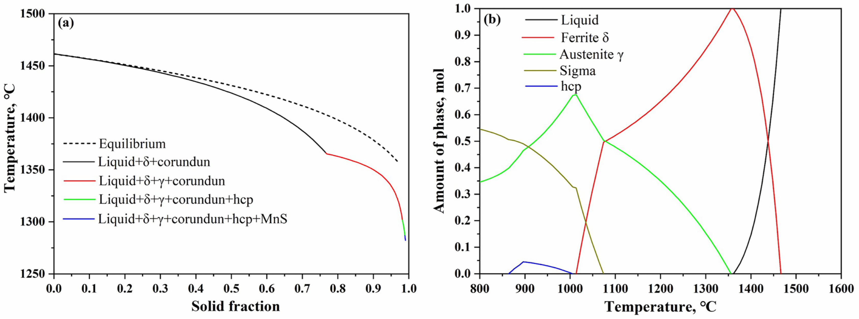
The solidification phase diagram and phase fraction during the solidification of S33207 steel was calculated using the Scheil solidification and equilibrium modules in Thermo-Calc 2022a, the results are shown in
Figure 1. The Scheil solidification module can calculate the actual solidification path of DSS S33207 under a non-equilibrium state and provide a basis for the solidification sequence in situ observation using the HT-CLSM. According to
Figure 1, the solidification sequence of S33207 steel calculated by both modules belonged to the ferrite–austenite mode (FA): L(liquid)→L +
δ (ferrite)→L +
δ + γ (austenite). This indicated that the
δ-ferrite phase started to form first followed by the
δ→γ transformation at the terminal stage of the solidification process. The morphologies of the crystallized phases can vary depending on the cooling rate, which has been discussed in detail in the following part.
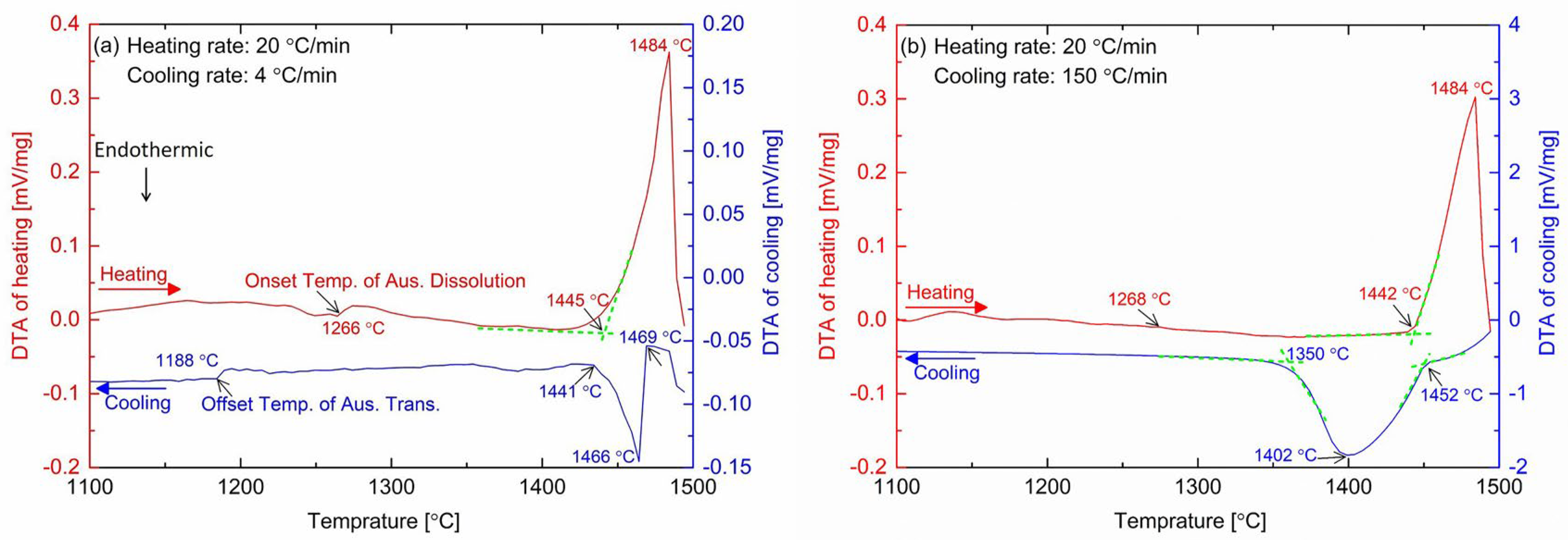
DTA results of the DSS33207 with the different solidification rates of 4 °C/min and 150 °C/min are presented in
Figure 2. For both measurements, the same heating of 20 °C/min was used to heat the specimen till 1550 °C, and two cooling rates with the same ones used for the HT-CLSM was performed here. The phase transition temperatures of the heating and cooling stages are summarized in
Table 2. In
Figure 2, it is shown that the liquidus and solidus temperatures during heating are almost overlapping since the heating rate was the same. The on-set and peak temperatures of the solidification varied a lot due to the influence of the solidification cooling rate. Slower cooling led to the much higher solidification temperatures obtained (i.e., 1469 and 1466 °C for the cooling rate of 4 °C/min; 1452 and 1402 °C for the cooling rate of 150 °C/min) in the DSS3207.
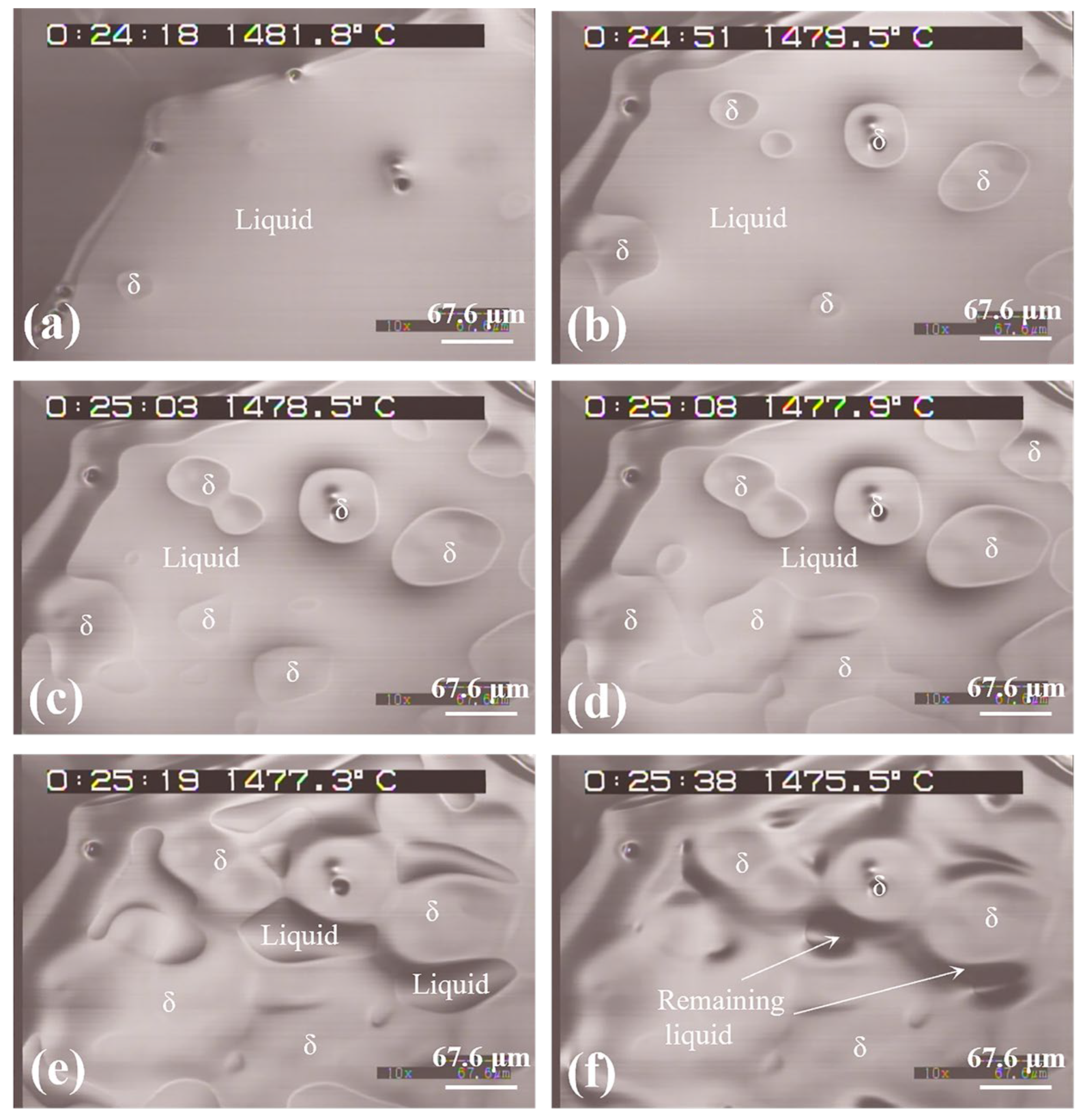
Figure 3 presents several representative micrographs of phase formation during the solidification process of the DSS33207 through in situ observations at a cooling rate of 4 °C/min. When the molten steel was undercooled to 1482.7 °C, the L→
δ transformation began to occur, and the formation of the cellular
δ phase was observed on the surface of the sample. It should be pointed out that a thin
δ layer formed on the outside of the liquid steel at the beginning of the solidification process (
Figure 3a). It is generally believed that the crucible provided a core for the heterogeneous nucleation of the new phase formation during the solidification observation by the HT-CLSM. Due to the slow cooling rate of liquid steel, pro-eutectoid
δ-ferrite solidified in the form of cellular crystals. With the decrease in temperature, the number of
δ-ferrite nuclei increased and the grains gradually grew up and coarsened. When the
δ-ferrite cell grew to some extent, several cells gradually approached and merged into a large irregular
δ cell, and there was no obvious boundary between these cells after merging (
Figure 3b). With further cooling, more
δ cells merged together and the remaining liquid between these
δ cells became less and less (
Figure 3c). The growth of
δ-ferrite was completed when the area of
δ cells was not obviously increased based on the HT-CLSM observations. Some amount of liquid was still present after the ferrite growth was complete (
Figure 3d), which has been reported in previous works [
27,
28].
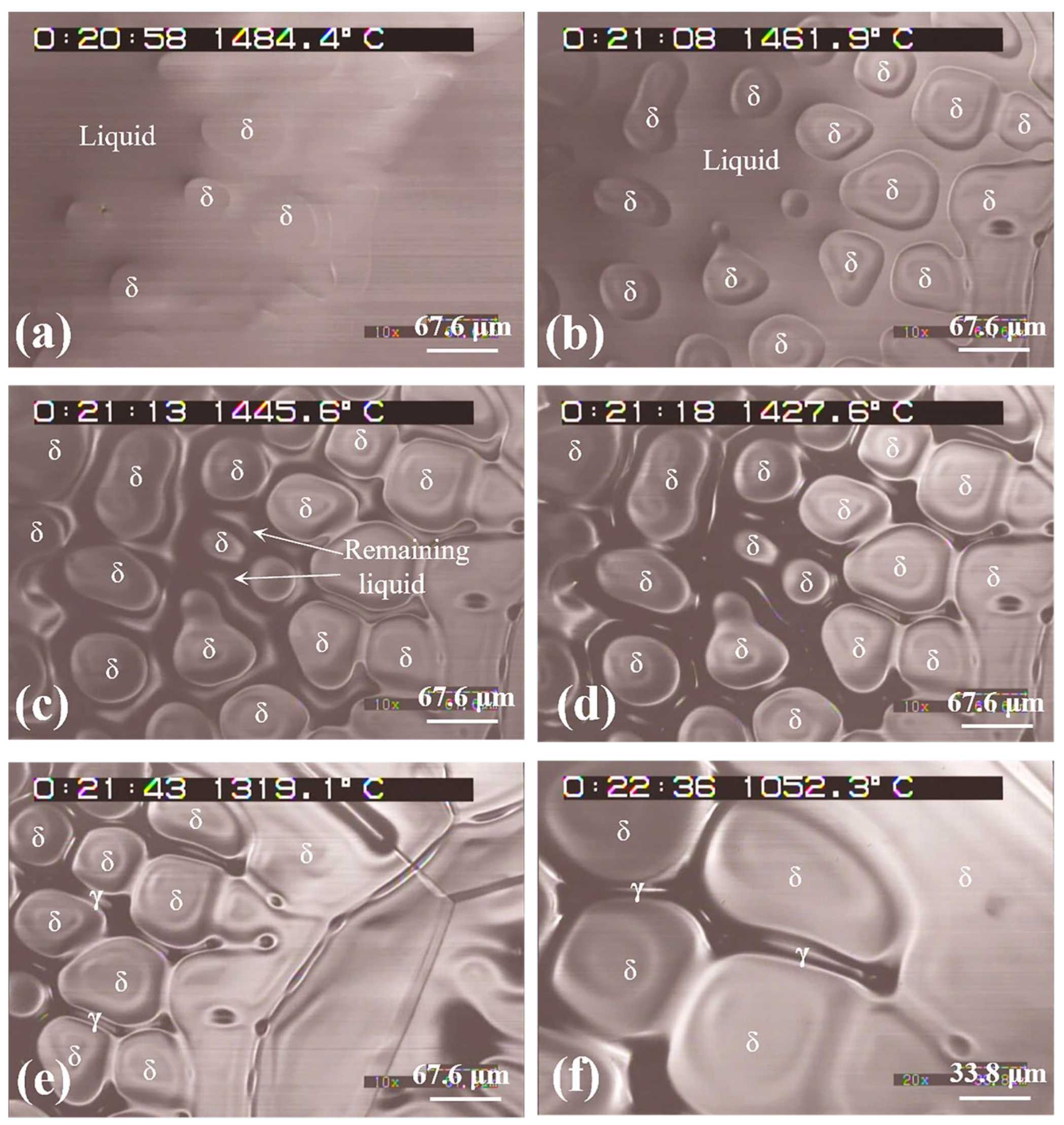
The solidification process of the
δ-ferrite phase with a cooling rate of 150 °C/min is shown in
Figure 4. It should be mentioned that the focus of the initial stage of
δ-ferrite nucleation from the liquid steel was not clear enough during the HT-CLSM observations made at this high cooling rate. Therefore, the formation temperature of
δ-ferrite on the liquid surface was not determined correctly. More
δ-ferrite cells can be formed simultaneously at the beginning of the solidification process compared to that of the low cooling rate. This indicated that a fast cooling rate favored primary
δ-ferrite nucleation. The increase of the cooling rate during the solidification process of steel increased the undercooling of the liquid steel’s composition, which promoted the increase in the nucleation rate of the
δ-ferrite phase. It is believed to be beneficial to the refinement of
δ cell crystals. Additionally, the growth temperature of the
δ-ferrite phase (
Figure 3b) formed at a higher temperature with a slow cooling rate. This tendency was the same as the DTA results (
Figure 2) as well as the previous work [
29], where a higher cooling rate resulted in a higher undercooling degree of melt and a lower crystallization temperature of
δ-ferrite. The
δ-ferrite grew quickly and a similar merging phenomenon was observed with a temperature decrease. In addition, a clear interphase boundary that usually separated these phases was observed (
Figure 4b). Under a high cooling rate, an obvious
δ-ferrite growth layer was observed outside of the original
δ cells due to the unstable growth characteristics of the
δ cells. The liquid area was pushed by the growth of
δ-ferrite during the late stage of the solidification process and then a volume shrinkage occurred between the
δ-ferrite phase boundaries (
Figure 4c). The growth rate of
δ-ferrite decreased due to less liquid having been left at this stage. With a further decrease in the temperature, the area of
δ-ferrite slowly increased and was kept at a stable value (
Figure 4d). This remaining liquid area was the place where the localized transformation occurred from
δ-ferrite to γ-austenite at a lower temperature. Generally, the concentration of the segregated elements increased greatly in the remaining liquid, where serious segregation took place [
27]. This segregation can result in the decrease in the solidifying temperatures for steel. With time having passed, the
δ-ferrite to γ-austenite transformation began at the
δ-ferrite boundaries (
Figure 4e,f). This finding is similar to that of Li et al. [
19], who reported that
δ→γ transformation occurred accompanied with a significant volume shrinkage.
However, the start temperature of the
δ to γ transformation was not able to be obtained clearly due to the limitation of resolution of uneven surface after solidification. It was reported that the
δ–γ phase transformation started earlier and occurred at a higher temperature in the S32101 DSS based on the concentric solidification technique with the increase in the cooling rate [
22]. However, Sun et al. [
21] found that starting temperature of the
δ–γ transformation at the slow cooling rate was higher than that at the rapid cooling rate in an S31308 DSS. Additionally, the slow cooling rate more strongly favored the nucleation and growth of the γ-phase than the rapid cooling rate due to the fact that the higher diffusion rates of elements and longer diffusion times were obtained at a lower cooling rate.
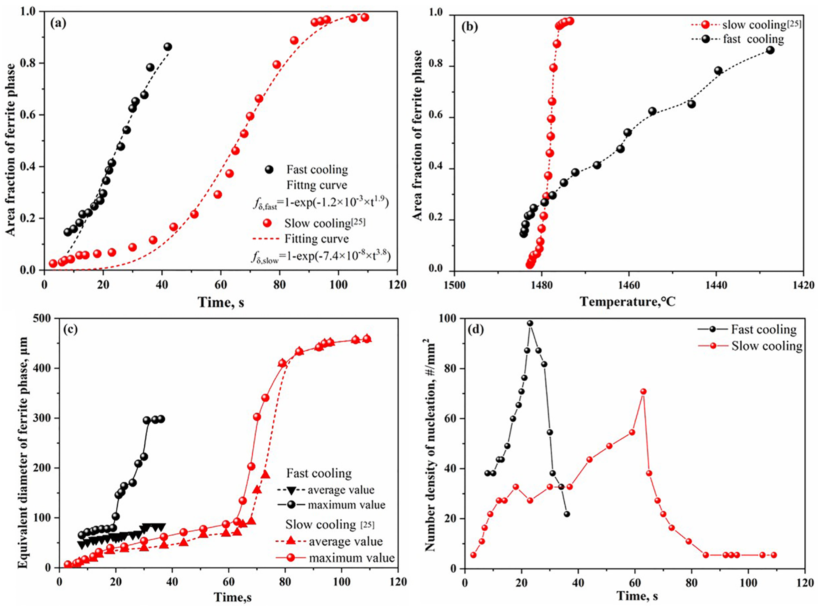
The area fraction of ferrite in multiple sets of video screenshots during the solidification process at different cooling rates and temperatures were evaluated by Image J software, and the Avrami equation was used to fit the relationship between the area fraction of ferrite and the time and temperature; the results are shown in
Figure 5. The Avrami Equations (1) and (2) [
30,
31] describe the crystallization of undercooled liquids into a solid state:
where is the area fraction of
δ-ferrite,
n is the Avrami coefficient,
k is the overall growth rate constant, and
t is the solidification time after the nucleation of
δ-ferrite,
tmax, the time required for maximum crystallization rate of ferrite.
It can be seen from
Figure 5a that the area fraction of
δ-ferrite increases with time, and it has a higher growth rate at a high cooling rate. In addition, the growth rate of
δ-ferrite showed smaller values at the initial and late stages of solidification and a higher value at the stable stage of the solidification process. As mentioned before, the formation point of
δ-ferrite in liquid was not obtained correctly, and thus the area fraction of
δ-ferrite curve was obtained using the Avrami fitting function when the fitted linear correlation coefficient (R
2) was greater than 95%. Furthermore, the area fraction of
δ-ferrite was less than one due to the adverse effects of its undulating cellular morphology on the depth of the observation field in the HT-CLSM image, which was more prominent under the high cooling rate. The fitted equations between the area fraction of
δ-ferrite (
fδ) and time in the cases of the cooling rates of 4 °C/min and 150 °C/min are expressed by Equations (3) and (4), respectively. The rate constant k represents the velocity at which liquid transforms to solid. According to the fitted equations, the larger growth rate constant can be obtained under the fast cooling rate, which indicates the larger growth rate of
δ-ferrite. This can be explained by the different number density of the nucleation sites and total growth times for the
δ-ferrite. Specifically, the time required for the maximum crystallization rate of ferrite under the slow cooling rate obtained from Equation (2) was calculated to be 113 s, which is almost five times longer than that under the fast cooling rate (23 s).
The growth of
δ-ferrite finished in a narrow temperature range (of less than 10 °C) at the cooling rate of 4 °C/min, while a much wider temperature was obtained at the cooling rate of 150 °C/min (
Figure 5b). Notably,
δ-ferrite began to form under a higher temperature with the growth ending at a lower temperature in the case of fast cooling compared to that of slow cooling. It is known that undercooling phenomenon usually occurs in the solidification process of steel, meaning that the ferrite formation temperature should be lower than the liquidus temperature of steel. From the in situ HT-CLSM observation results of the solidification process, the
δ-ferrite formation temperature was slightly higher but has the same tendency as the results measured by DTA, which has been presented in
Figure 2. This can be attributed to the details of the different instrumentation settings (sample size, thermocouple position, etc.) between the DTA and HT-CLSM measurements.
In terms of the maximum and average diameter changes of
δ-ferrite (
Figure 5c), the maximum diameter of
δ-ferrite slowly increased at the beginning and began to increase rapidly when the
δ-ferrite grew to a certain extent. The maximum and average diameter changes of
δ-ferrite showed a similar tendency in the case of slow cooling, while the average diameter of
δ-ferrite gradually increased during the whole solidification period under a fast cooling rate. As a result, the average diameter of
δ-ferrite at the end of the solidification stage was approximately 80 μm at the cooling rate of 150 °C/min compared to 460 μm at the cooling rate of 4 °C/min, respectively. It can be indicated that the faster cooling rate can result in a smaller size of
δ-ferrite. Moreover, the larger number density of the nucleation sites of
δ-ferrite at the beginning of solidification can be found in the case of a high cooling rate, as shown in
Figure 5d. The peak of the number density of the nucleation sites curves indicates that no new nucleation sites can be formed after that point, and the existing nucleation phases start to grow and merge to form bigger cells. In combination with the evolution of the number density of nucleation sites and the diameter of
δ-ferrite changing during the solidification of steel, we can conclude that a slow cooling rate favored the growth of
δ-ferrite, whereas a high cooling rate favored the nucleation of
δ-ferrite.
In conclusion, the grain size will be finer as the cooling rate increases, the morphology comprises smaller grains, and the solidification behavior will commerce faster. This information can guide the actual continuous casting process of DSSS33207s.
3.3. Comments on the Microstructure Evolution after Solidification
The nitrogen (N) content in the DSSs is one of the important elements used to determine the austenite formation temperature and fraction. Normally, the nitrogen was forced to be added into the DSSs in the liquid by e.g. pressure metallurgy. However, during the solidification process, and in the
δ-ferrite phase, the solubility of N is much lower compared to the original amount, meaning the nitrogen will lose during in situ observations using Ar gas. In order to confirm this, the original DSS33207 alloy as well as the specimens after solidification with different rates are shown in
Table 5; the data was measured by LECO analysis. It is seen that the N content after solidification was much lower than the original one (0.47%), which led to an unbalanced fraction between
δ-ferrite and austenite. In fact, the loss of nitrogen during the melting and solidification of the DSSs is the actual limitation of the in situ observations of DSSs, and this process is inevitable. However, the obtained results are still quite useful and meaningful, since this simulates the actual case of DSS an as-cast ingot and heat-affected zone (HAZ) of welding, which also have a very low N content.
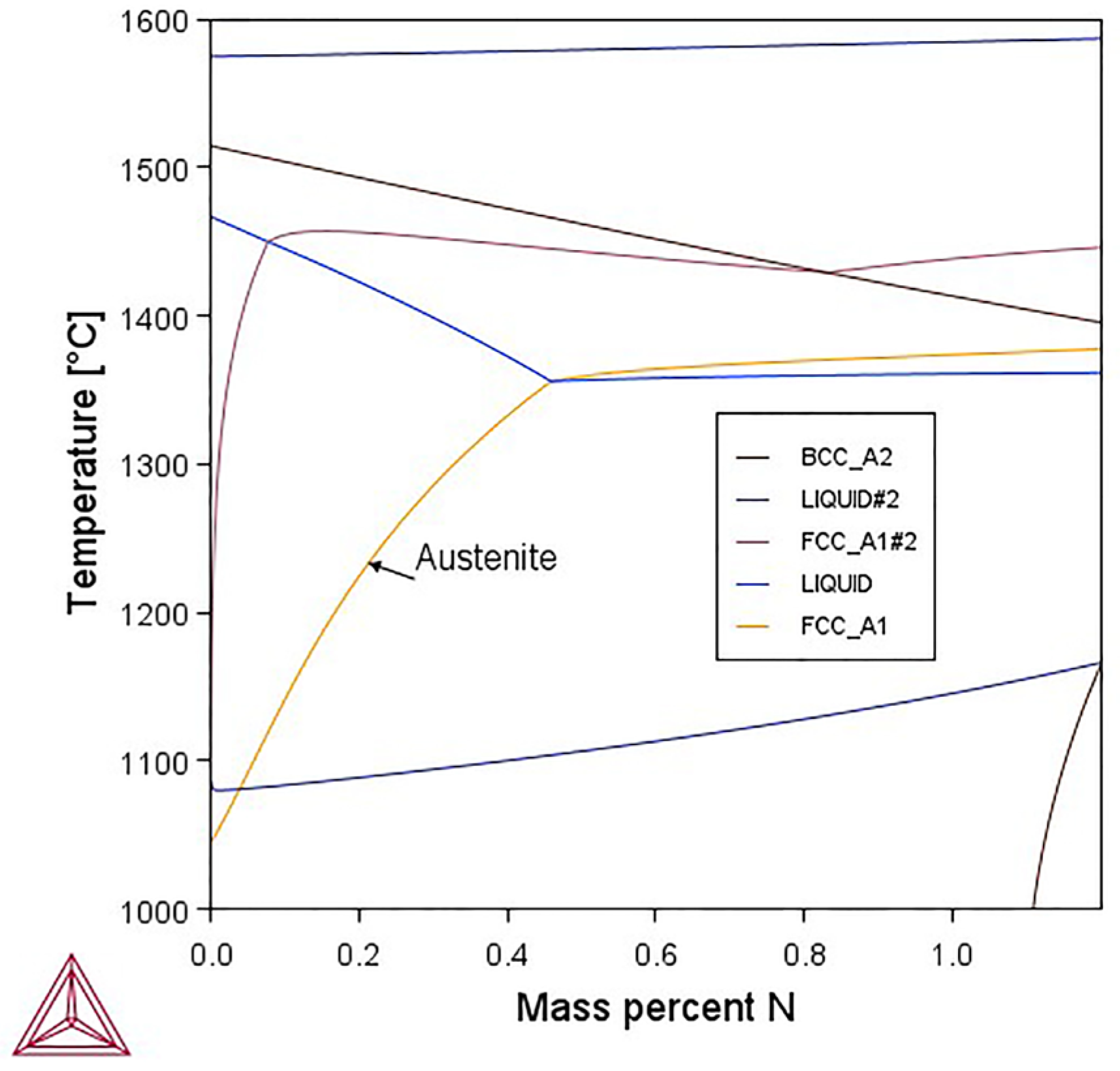
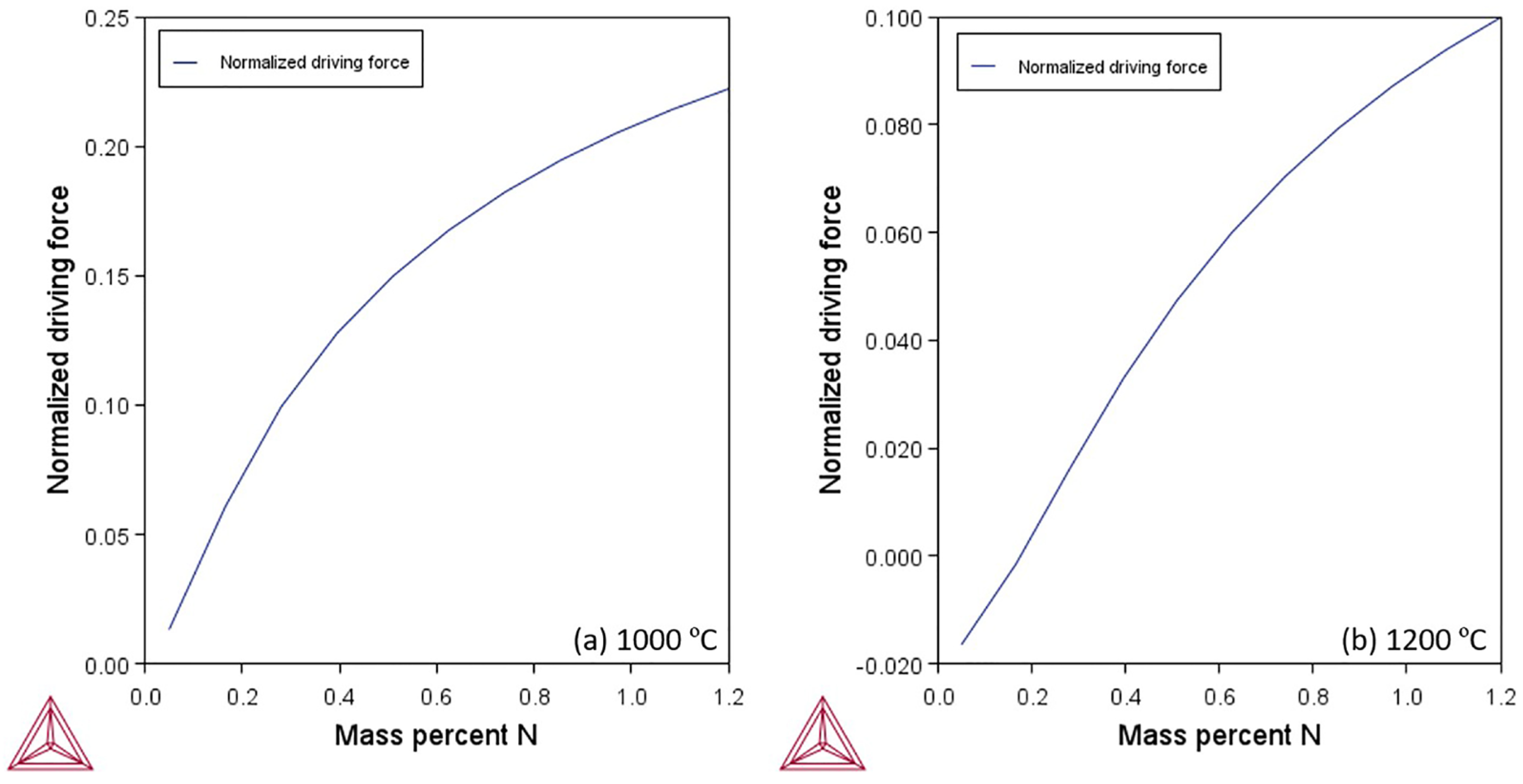
Thermodynamic calculations using Thermo-Calc 2023b with the TCFE12 database were used to calculate the phase diagram as well as the driving force of austenite in the DSS33207 with the increase in N content. The results are presented in
Figure 11 and
Figure 12. In
Figure 11, the stable phase region of austenite was much larger when N was relatively higher since N stabilizes the FCC phase. Furthermore, the normalized driving force of austenite also significantly increased the increasing N content, which can be seen in two typical temperatures of 1000 and 1200 °C, respectively, as shown in
Figure 12. It is worth mentioning that the driving force value at 1000 °C is always higher than that at 1200 °C since lower temperatures always facilitate austenite formation.
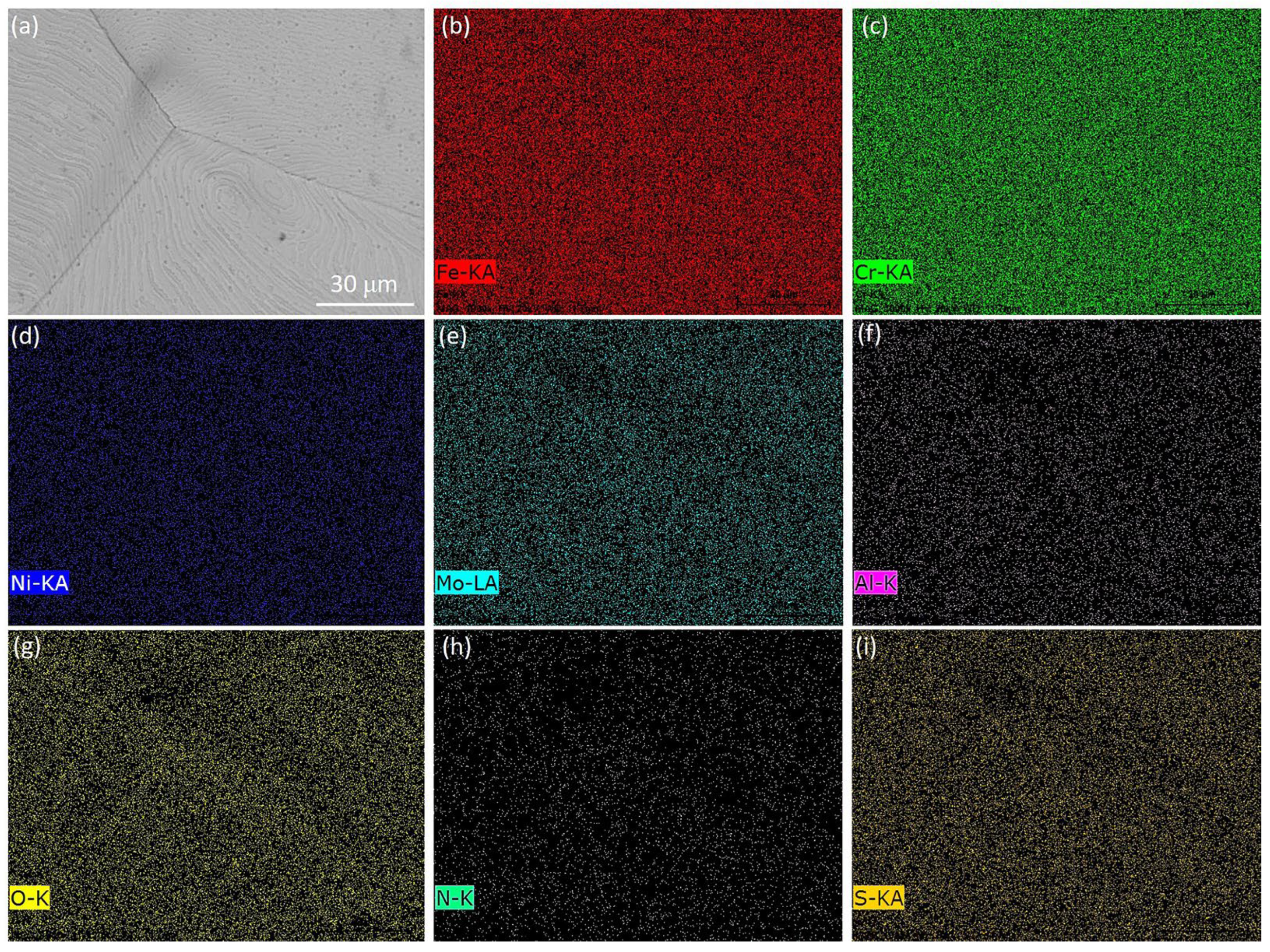
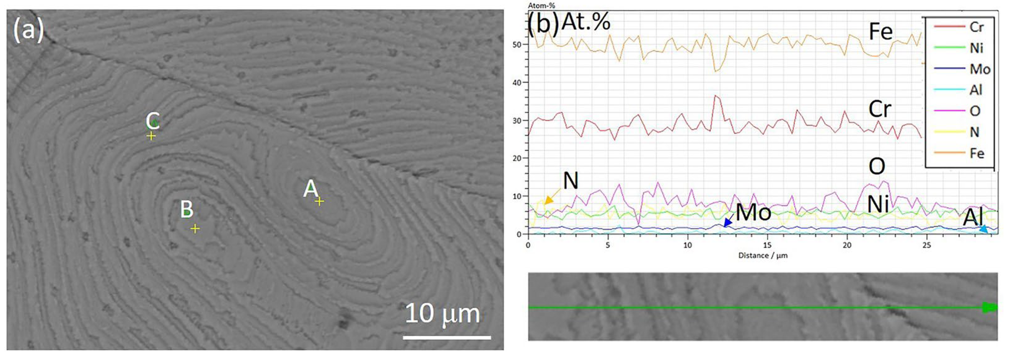
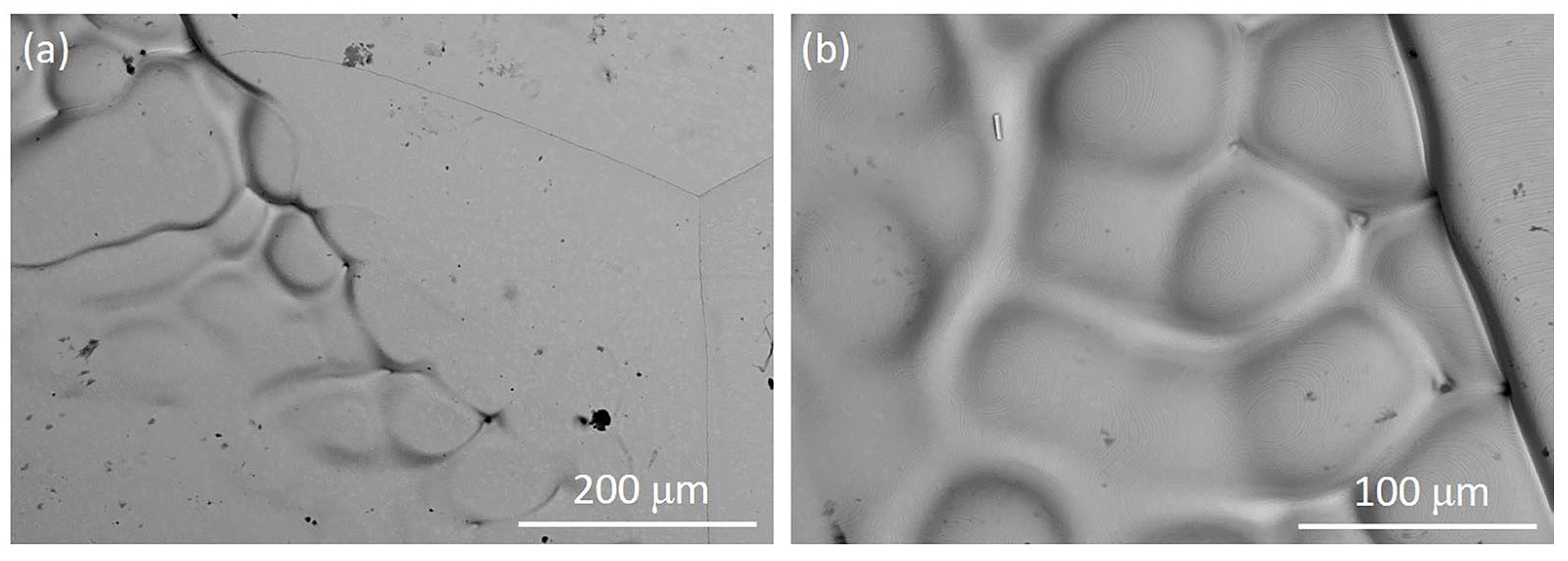
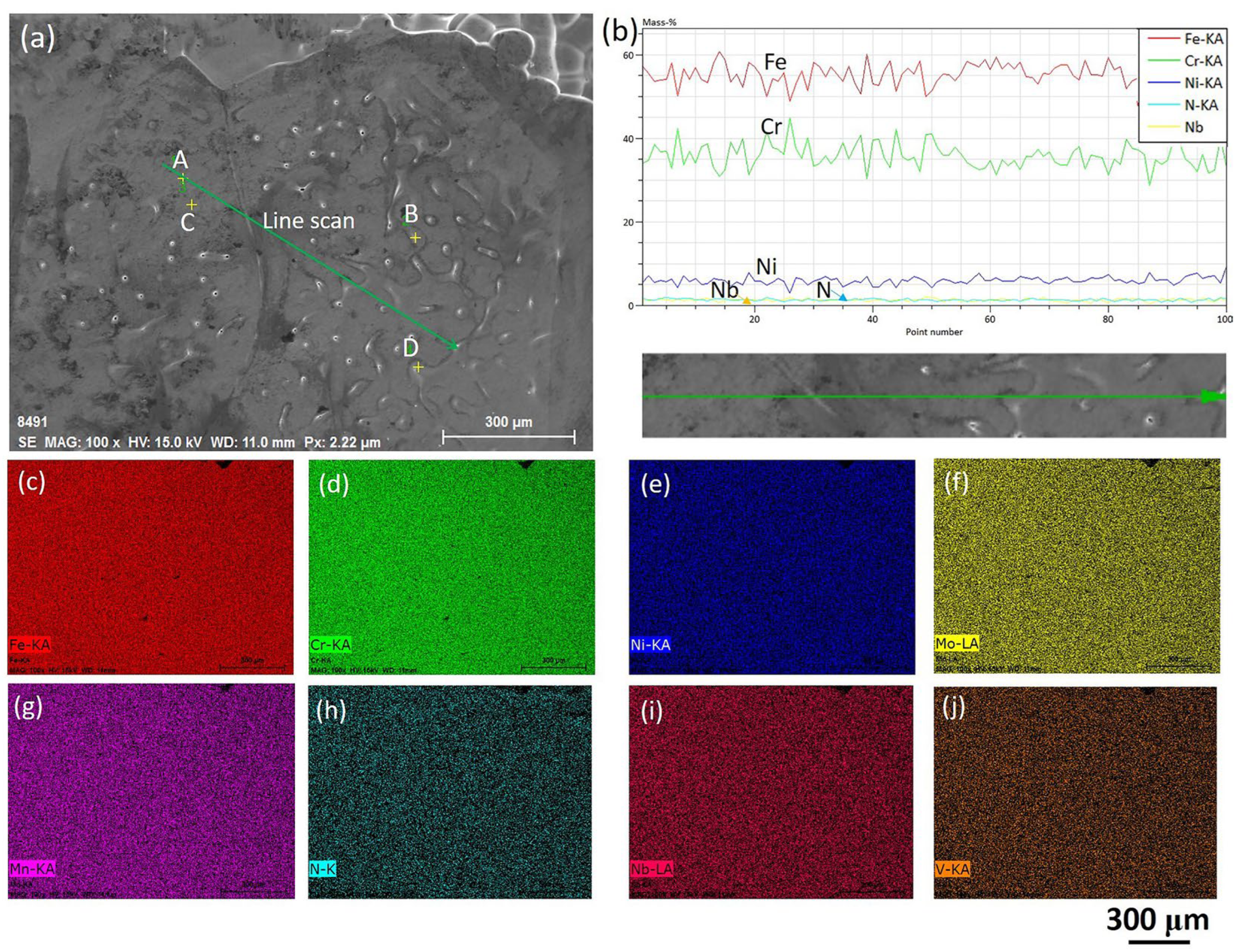
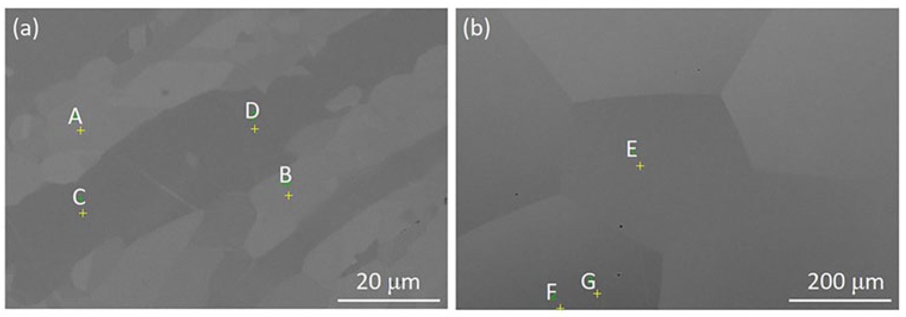
Based on these calculations, it is known that the loss of N in the DSS3207 will lead to a decrease in the austenite fraction in the matrix. A typical microstructure of the as-received and solidified (fast cooling with a 150 °C/min) DSS33207 is displayed
Figure 13. In
Figure 13a, austenite (points A and B) presents the bright phase while ferrite (points C and D) presents as the dark matrix; the detailed composition of each phase is shown in
Table 6. Chemical compositions of N and C are calculated by Thermo-Calc, and the rest was measured using an EDS. It is shown how N and Ni are obviously higher in the austenite phase than that in the ferrite phase, making it easy to identify the FCC structure. Also, a balanced mixture of each phase is shown in
Figure 13a. In the solidified microstructure, it is almost the single ferrite phase since the polygonal morphology grain size can be seen, and the austenite can still be recognized due to the contrast difference. According to the unpublished work by the authors, the fraction of austenite in the vertical section of the DSS sample after solidification was around 5%, measured by EBSD. Points E and G represent the ferrite and austenite in the solidified sample. The composition of each phase was almost the same as the one in the as-received sample. Point F seems to be a mixture of both phases since the morphology of the newly formed austenite after solidification seems to resemble a tiny island morphology [
25].
The obtained finding regarding the unbalanced microstructure is the normal case when using Ar as the protection gas during solidification. One potential solution to fix this is adding external thermal aging at the austenite temperature to trigger the second austenite formation [
2]. Another solution is mixing N
2 with Ar to use in the HT-CLSM observation, which will supply the N loss; however, a reverse problem leading to N
2 being undertaken may occur. It has been reported that when using N
2 as the protection gas, the DSS changes to become an almost single FCC phase steel [
32]. In this case, the ratio of mixing N
2 with Ar needs to be optimized in future work.


