Abstract
This study investigates the fatigue damage evolution mechanisms of D2 wheel steel under high-cycle uniaxial and multiaxial loading conditions, with a focus on determining the fatigue crack growth threshold (FCGT). Uniaxial and multiaxial FCGT tests were performed on pre-cracked D2 wheel steel specimens subjected to high-frequency cyclic loading at stress ratios (R) of 0.1. The results indicate that the FCGT for D2 wheel steel under uniaxial loading conditions ranges between 8–9 MPa.m0.5, while under multiaxial loading conditions, it ranges between 6–9 MPa.m0.5. Scanning electron microscopy analysis revealed differences in the crack propagation mechanisms between the uniaxial and multiaxial tests, with cracks deviating from their path and following the microstructure in the uniaxial tests, and cracks propagating along planes of weakness in the multiaxial tests. These findings provide insights into the high-cycle fatigue behavior of D2 wheel steel under different loading conditions for potential applications in the railway industry.
1. Introduction
Rim rolling contact fatigue and rim cracking are critical issues in the railway industry, as they can result in train derailment and fatal accidents [1]. Wheel–rail contact, which occurs in a small area of less than 100 mm2, exposes the wheel to complex random dynamic and impact loads amounting to several tons [2]. These loads, combined with longitudinal friction at the contact point, can cause surface material wear and the formation of internal cracks, known as peeling or fish scale cracks, below the tread [3]. When dynamic stress interacts with the rim material’s inherent microstructure, deeper cracks may form and eventually lead to fatigue fractures, posing a significant risk [4]. The challenge in addressing rim cracking is that it is a complex phenomenon that can be influenced by various factors, including material properties, loading conditions, and environmental factors [5]. Several studies have been conducted to investigate the mechanisms of fatigue cracking, with a focus on identifying the factors that contribute to crack initiation and propagation [6,7,8]. For example, in a study conducted by Nejad and colleagues [9], a numerical simulation was carried out to analyze the impact of residual stresses on the crack growth behavior of railway wheel rims. The findings of their investigation indicated that residual stresses have a notable influence on the crack growth behavior, and the position of the maximum residual stress can alter based on the wheel–rail contact position. In a separate investigation by Nejad [10], finite element analysis was employed to explore the impact of various loading conditions on the fatigue crack propagation behavior of railway wheel rims. The outcomes of this study demonstrated that the crack propagation rate is subject to the type of load, amplitude of the load, and the location of the crack tip. To address the challenge of rim cracking and improve the safety and reliability of railway transportation, researchers have proposed various approaches, including the use of new materials, improved design, and advanced testing methods. For example, Suetrong et al. [11] developed a new type of railway wheel material, which exhibited improved fatigue resistance and better crack propagation behavior compared to traditional materials. In addition, Lisowski et al. [12] proposed a new design for railway wheel rims that uses a variable thickness structure to reduce stress concentration and improve fatigue resistance. Advanced testing methods, such as multiaxial fatigue testing, have also been proposed to better replicate the dynamic compressor-shear fatigue stress state experienced by the rim material in service [13]. These testing methods can provide more accurate and reliable data on the fatigue behavior of the rim material, enabling better prediction and management of failure mechanisms [14,15,16]. Given the significance of exploring the mechanisms underlying the degradation and failure of diverse materials, a considerable study has been undertaken to address this topic [17,18,19].
Braking without tread can exacerbate these issues, as it introduces high-pressure stress at the wheel–rail contact point, creating a plastic state in the material and generating residual stress and a “ratchet” effect. This stress field interacts with longitudinal and transverse loads, causing alternating shear stress in the rim material at different depths. In the absence of significant defects, the crack depth in low axle load wheelsets is typically 3 to 5 mm; however, when defects are present, the crack depth can reach up to 22.23 mm [20]. Moreover, the impact load of the wheel and rail greatly contributes to crack initiation and propagation [21]. The use of high-performance materials and advanced design concepts has been proposed to address the issues of rim cracking and improve the safety and reliability of railway transportation. For example, Bendikiene et al. [22] proposed a new type of railway wheel material that uses high-strength steel and has a refined microstructure, which can effectively improve the fatigue resistance and crack propagation behavior of the material. The study showed that the new material exhibited a lower crack initiation rate and a higher threshold for crack propagation compared to traditional materials. In addition to material and design improvements, advanced testing and monitoring techniques have also been proposed to better identify and manage rim cracking. For example, acoustic emission (AE) testing has been used to detect and monitor fatigue cracks in railway wheels and other components [23]. AE testing can detect the high-frequency elastic waves generated by crack growth and provide real-time information on the location and size of the crack. Similarly, vibration-based monitoring techniques have been used to detect and diagnose faults in railway wheelsets [24]. Vibration-based monitoring can detect changes in the dynamic behavior of the wheelset caused by defects or cracks and provide early warning of potential failures using the importance of vibration analysis [25,26,27]. Furthermore, the use of advanced simulation techniques [28,29,30], such as finite element analysis (FEA), can provide valuable insights into the stress and strain behavior of railway wheelsets and help optimize material selection, design, and maintenance strategies. For example, Arslan et al. [31] employed finite element analysis (FEA) to examine the impact of diverse loading conditions on the stress and strain behavior of railway wheelsets. The outcomes of their study indicated that the distribution of stress and strain in the wheelset can vary considerably dependent on the loading condition, and that the maximum stress and strain location can alter with the wheel–rail contact position. In a similar vein, Kwon et al. [32] employed FEA to scrutinize the influence of residual stress on the fatigue behavior of railway wheel rims. The study revealed that the fatigue crack propagation behavior of the rim material can be significantly affected by the magnitude and location of the residual stress. The implementation of numerical analyses, such as the Finite Element Analysis, could potentially result in a decrease in design expenses [33].
Numerous studies have been undertaken to analyze the behavior of diverse materials and structures subjected to distinct loading conditions [34,35,36]. Thermal loads, caused by braking on the wheel tread, can reach temperatures as high as 840 °C, leading to a complex alternation of thermo-mechanical loads [37,38,39]. This process can promote fatigue damage, crack initiation, and propagation while also potentially causing martensitic transformation of the material, which further impacts the residual stress field [40,41]. To mitigate the effects of thermal loads on railway wheelsets, various cooling methods have been proposed, including air cooling and water cooling. For example, Jiang et al. [42] proposed a new air cooling system that uses a high-speed air jet to cool the wheel tread during braking. The study showed that the new cooling system can effectively reduce the peak temperature of the wheel tread and improve the thermal stability of the material. Similarly, Liu et al. [43] proposed a new water cooling system that uses a high-pressure water jet to cool the wheel tread. The study showed that the new cooling system can achieve a cooling rate of up to 100 °C/s and significantly reduce the residual stress and crack propagation rate of the material. In addition to cooling methods, advanced material and surface treatments have also been proposed to improve the thermal stability and fatigue resistance of railway wheelsets. For example, Chang et al. [44] developed a new type of railway wheel material that uses a surface modification technique to improve its thermal stability and wear resistance. Similarly, Song et al. [45] proposed a new surface treatment technique that uses laser shock peening (LSP) to enhance the fatigue resistance and crack propagation behavior of railway wheelsets. Moreover, the impact of thermal loads on railway wheelsets can be better understood through advanced modeling and simulation techniques. For example, Tian et al. [46] used a multi-physics model to simulate the thermal-mechanical behavior of railway wheelsets during braking. The model takes into account the heat transfer, mechanical deformation, and stress distribution in the material, and can provide insights into the thermal stability and fatigue behavior of the material under different loading conditions. Similarly, Lingamanaik et al. [47] used a coupled thermo-mechanical model to investigate the effects of different cooling methods on the residual stress and crack propagation behavior of railway wheelsets. The study showed that the cooling method can significantly affect the residual stress and crack propagation behavior of the material and that the cooling rate and cooling medium have significant impacts on the material’s thermal stability.
Rim cracking is fundamentally a fatigue damage evolution issue in rim materials under dynamic compression-shear multiaxial fatigue stress during rolling contact fatigue [48]. Existing research, which primarily focuses on rolling contact creep testing and finite element simulation combined with strain-life (ε-N) theory, has been effective in analyzing wheel tread wear and surface peeling problems but provides no direct evaluation analysis basis for rim cracking, a random dynamic compressive shear fatigue failure [49,50,51]. To better understand the fatigue behavior of railway wheelset rims and predict the occurrence of rim cracking, researchers have proposed new testing and modeling methods that take into account the complex multiaxial stress state and material heterogeneity [52,53,54]. For example, Yong et al. [55] developed a new testing method that uses a tri-axial compression-shear fatigue testing machine to simulate the multiaxial stress state experienced by the rim material during rolling contact fatigue. The study showed that the new testing method can effectively reproduce the fatigue behavior of the material and provide a more accurate prediction of the material’s fatigue life. Similarly, Arfa et al. [56] proposed a new modeling method that uses a multi-scale finite element model to simulate the microstructure and material heterogeneity of the rim material. The model can provide insights into the stress and strain behavior of the material at different length scales and predict the occurrence of rim cracking under different loading conditions. Moreover, advances in non-destructive testing (NDT) techniques have enabled more accurate and reliable detection of rim cracking and other defects in railway wheelsets. For example, Sabato et al. [57] used a digital image correlation (DIC) technique to detect and measure the strain and deformation of railway wheelsets during service. The technique can provide high-resolution and real-time data on the stress and strain behavior of the material and enable early detection of fatigue cracks and other defects. In addition, researchers have evaluated the impacts of various factors on the fatigue behavior of railway wheelset rims. For example, Nikas et al. [58] studied the impacts of material composition and microstructure on the fatigue behavior of railway wheelset rims using a combination of experimental testing and microstructural analysis. The study showed that the material composition and microstructure have significant impacts on the fatigue behavior of the material and that the presence of inclusions and other defects can significantly reduce the material’s fatigue life. Similarly, Banerjee et al. [59] investigated the effects of wheelset speed and axle load on the fatigue behavior of railway wheelset rims using a multi-physics finite element model. The study showed that the wheelset speed and axle load can significantly affect the stress and strain behavior of the material and that high-speed and heavy-load operations can increase the risk of rim cracking and other defects. In two studies by Ostash et al. [60,61], the relationship between the fatigue crack growth resistance characteristics of steel and tread surface damage of railway wheels was investigated. It was found that the cyclic fracture toughness of the wheel steel ∆KI fc and ∆KII fc, determined at Mode I and Mode II fracture mechanisms, were the determining parameters for the growth of tread surface damage. Additionally, the authors proposed a new concept for selecting steels for high-strength railroad wheels based on the characteristics of cyclic crack-growth resistance under the conditions of Mode I and Mode II fractures.
Additionally, there is a need to understand the dynamic damage evolution mechanism of hub materials under fatigue stress of the compression-tensile axis related to the hub-circumferential crack phenomenon. The hub material is affected by the interference assembly of the axle and is always in the fatigue stress state of compression-multiaxis in service [62,63]. However, there is no specific research on this key issue at home and abroad. Therefore, there is a need to reveal the evolution process of radial fatigue crack initiation, propagation, and fracture of hub materials under similar service stress conditions and establish the representation method and probabilistic safety analysis method of such fatigue damage behavior [64,65].
The railway industry holds immense significance in today’s world, prompting several researchers to scrutinize crucial parameters in this sector [66,67,68]. The investigation and improvement of materials utilized in this industry are among the noteworthy parameters that warrant attention [69,70,71]. In summary, the fatigue damage and cracking problems in wheel materials pose a significant threat to the safety and reliability of railway transportation. While previous studies have focused mainly on wheel tread wear laws and surface peeling problems, there is a need for systematic experimental studies on the dynamic compressor-shear fatigue stress state of the deep material of the rim to reveal the fatigue crack initiation, propagation, and fracture evolution process. Moreover, there are gaps in the literature review, such as the dynamic damage evolution mechanism of hub materials and spoke materials under fatigue stress. This project aims to address these gaps and establish the characterization method of damage behavior and the probabilistic safety analysis method to ensure long life and highly reliable service requirements near 109 cycles. Therefore, to address the research gaps identified, this study aims to investigate the fatigue damage evolution mechanism of D2 wheel steel under high-cycle uniaxial and multiaxial loading conditions. Uniaxial and multiaxial FCGT tests were conducted to determine the fatigue behavior and understand the crack propagation behavior of D2 wheel steel. The tests were performed under loading conditions that accurately simulate the stress states experienced by wheel materials during operation. Scanning electron microscopy (SEM) analysis was also performed to examine the microscale behavior of the propagated cracks. This study’s primary novelties are its determination of the fatigue crack growth threshold of D2 wheel steel under both uniaxial and multiaxial loading conditions, which may provide insights into the mechanisms of crack initiation and propagation in this material. Additionally, the study examined the influence of loading conditions and microstructure on the fatigue behavior of D2 wheel steel using scanning electron microscopy analysis. These findings may be crucial in understanding how cracks form and propagate in D2 wheel steel and can aid in the development of safer and more reliable materials for high-speed rail applications.
2. Experimental Procedure
To evaluate the uniaxial FCGT behavior of the high-strength low-alloy steel test sample, the test was conducted according to the standard procedure using 8–10 samples [72,73,74]. The test involved the precasting of a crack in the sample, followed by a load reduction threshold test. The specifications of the specimens utilized in the uniaxial FCGT tests, including their dimensions and geometry, are presented in Table 1 and Figure 1, respectively. The loading scheme was confirmed and discussed, with an initial ∆K value of 11 MP.m0.5 and a reduction of 1 MP.m0.5 per 105 cycles until da/dN reached 10−11 m/cycle. The load reduction spectrum was compiled and the test was stopped when da/dN reached 10−11 m/cycle, with the record file tracked and checked to confirm the results. As per the guidelines provided by ASTM E647, a threshold value of 10–11 m/cycle for the fatigue crack growth rate was chosen for this study. The results of the uniaxial FCGT tests provided essential information for the subsequent compression-shear multiaxial fatigue behavior tests. Table 2 lists the dimensions of the specimens utilized in the multiaxial fatigue tests, and the sampling positions and geometry were depicted in Figure 2. To accurately monitor the behavior of the specimens during testing, a Videomex-S high-speed video camera system (WEINSCOPE, Jinhua, China) was utilized. The testing method and fixture device developed in this study enabled the accurate and reliable testing of the multiaxis and high-cycle fatigue behavior of materials (D2 wheel steel) subjected to wheel service loads, providing insights into the material’s fatigue behavior under high-cycle and high- frequency loading conditions. These findings lay the foundation for further research in this field, with potential applications in the railway industry and other areas that require the reliable and safe operation of high-stress components.

Table 1.
Dimensions of specimens utilized in uniaxial FCGT tests.
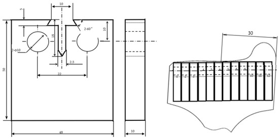
Figure 1.
Geometry of the test sample and sampling positions for uniaxial fatigue crack growth threshold tests.
Table 2.
Dimensions of tested specimens in compression-shear multiaxial fatigue behavior tests.
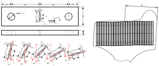
Figure 2.
Geometry of the test sample and sampling positions for compression-shear multiaxial fatigue behavior tests.
The multiaxis fatigue test fixture device was specifically designed to apply a combination of compression and shear stresses to the test sample. The fixture device consisted of a loading head, a loading rod, and a loading plate connected by ball joints. The loading head was designed to apply the compression load, while the loading plate applied the shear load. The loading rod was adjustable to ensure correct alignment of the loading direction. The fixture device was mounted onto the uniaxial high-frequency testing machine, enabling the application of a high-frequency cyclic load to the test sample [75,76,77]. Figure 2 illustrates the specimens used for the compression-shear multiaxial fatigue behavior tests, and Table 2 tabulates the dimensions of these specimens. To obtain samples for testing, the sample wheel was used as a reference for the specified geometry and position. A total of 10 samples were taken, and tested with an angle of 15°. This allowed for the systematic testing and analysis of the samples across a range of angles, providing a comprehensive understanding of the material’s behavior under different loading conditions. To perform the multiaxis fatigue test, the test sample was carefully mounted onto the fixture device. The loading head and loading plate were then brought into contact with the test sample, and the loading rod was adjusted to ensure correct alignment of the loading direction. The test was conducted under a high-frequency cyclic load, with the loading ratio and loading frequency controlled by the testing machine. In this study, the loading ratio was set to 0.1, defined as the ratio of the minimum stress to the maximum stress, and the loading frequency was set to 50 Hz to simulate actual wheelset operation conditions. During the test, the stress and strain of the test sample were monitored using strain gauges and displacement sensors, respectively. Following the debugging and installation of the sample, a high-speed camera was installed to ensure that the sample was within the field of view and could be observed from both sides. The installation of the high-speed camera was critical to the success of the testing process, as it allowed for accurate and detailed observation of the sample’s behavior during testing. This ensured that any potential issues or anomalies could be identified and addressed in real-time, maximizing the accuracy and reliability of the testing results. In this study, the D2 wheel steel specimens were obtained from Baosteel Group Co., Ltd., a commercial alloy steel supplier based in Shanghai, China. The chemical composition of the D2 wheel steel used in this study was as follows (wt.%): 1.5% carbon, 0.3% silicon, 0.3% manganese, 1.1% chromium, 0.05% molybdenum, 0.05% vanadium, and the balance consisting of iron. The tension-compression fatigue tests were conducted using an INSTRON testing system, which was manufactured by a company based in Norwood, MA, USA.
SEM Analysis of Wheel Rim Cracking Behavior
In this study, the specimens were evaluated using SEM images to observe the behavior and regularity of cracking in high-speed and heavy-load wheel rim materials. The SEM images were taken after fatigue tests and the propagation of cracks due to the uniaxial FCGT test results and multiaxial FCGT test results on D2 wheel steel, which have potential applications in the railway industry. The SEM analysis was performed using JEOL JSM-7800F (JEOL Ltd., Tokyo, Japan) Prime to capture high-resolution images of the microstructure of the specimens. The microscopy observations allowed for a detailed examination of the causes and behavior regularity of the rims’ cracking behavior. Based on the SEM images and relevant technical means, a characterization model or method was proposed for the studied wheel rim materials.
3. Results and Discussion
3.1. Uniaxial Fatigue Crack Growth Threshold Test Results
The uniaxial FCGT tests were conducted according to the described method for investigating rim rolling contact fatigue and rim cracking problems in the railway industry. The tests were performed using D2 wheel steel as the test material. Figure 3 illustrates the sample before the start of the test and the sample during the test inside the fixture.
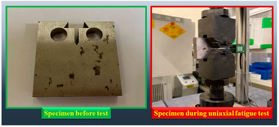
Figure 3.
Preparation of D2 wheel steel specimens for uniaxial FCGT tests: before and during testing.
The input sample parameters for the uniaxial FCGT tests are presented in Table 3, with a stress ratio of 0.1 and a stress intensity factor (Delta K) value of 11 chosen as input control parameters. The static load value was calculated to be 3.16 KN, while the dynamic load value was 2.59 KN. The real-time crack data was monitored, and the test was suspended when the prefabricated crack reached 9.03 mm, with the prefabricated crack data saved.
Table 3.
Input parameters of samples in uniaxial FCGT tests.
For the threshold test, the sample parameters were input again, with a change of 0 to 9.03. The static load value was recalculated to be 2.92 KN, while the dynamic load value was 2.38 KN, and these values were input into the control software to initiate the data acquisition program. The crack growth data was recorded, and the test was stopped when the crack growth rate fell below 10−7 m/c and the crack was no longer growing. The sample was then removed, photographed, and the recorded data saved.
Figure 4 depicts the specimens tested after the uniaxial FCGT test, and Table 4 presents the recorded data obtained during the test, including data collected at different intervals. The obtained results from the uniaxial fatigue crack growth threshold tests provide crucial insights into the fatigue damage mechanism of D2 wheel materials and the brittle mechanism caused by structural constraints. Based on the recorded data in Table 4, it can be inferred that the crack growth rate exhibited an upward trend over time, reaching its peak value of 1.35 × 10⁻⁵ m/cycle before gradually declining. The observed crack behavior during the tests revealed a combination of crack initiation, propagation, and final failure. The initial crack initiation occurred at the corner of the sample, while crack propagation was predominantly perpendicular to the applied load direction. The final failure of the samples occurred due to the merging of multiple cracks, leading to complete fracture of the sample.
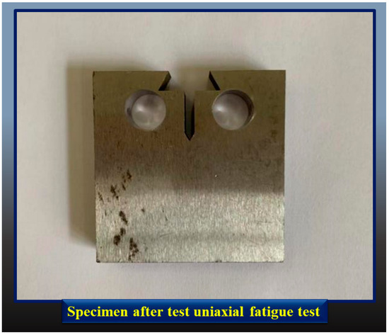
Figure 4.
Specimens after the uniaxial FCGT test.
Table 4.
Recorded data from the uniaxial FCGT test, including data collected at different intervals.
The results in Table 4 demonstrate a clear increasing trend in the crack growth rate with increasing cycle count. The crack growth rate increased from 1.787 × 10⁻⁷ m/cycle at cycle count 12,278 to a maximum of 22.279 × 10⁻⁷ m/cycle at cycle count 185,725 before decreasing again. This increase in crack growth rate indicates that the fatigue damage was accumulating in the sample with continued cyclic loading. The drop in crack growth rate after the peak suggests the onset of crack growth retardation mechanisms as the crack tip becomes more blunted. The applied stress intensity factor, ΔK, also had a significant influence on the crack growth behavior. As ΔK was reduced in steps from 11 MPa.m0.5 to 8.124 MPa.m0.5, the crack growth rate decreased correspondingly. For example, at a ΔK of 11 MPa.m0.5, the crack growth rate was 1.787 × 10⁻⁷ m/cycle, while at ΔK of 10.146 MPa.m0.5, the crack growth rate dropped to 0.453 × 10⁻⁷ m/cycle. This demonstrates that higher stress intensity factors result in faster crack growth rates, as expected based on fracture mechanics principles. The results also show the transition of the crack growth mechanism from initiation to propagation and finally complete fracture. The crack growth rate was initially slow, increased rapidly as the crack started propagating, and finally slowed down again as the crack approached complete fracture. For example, the crack grew from 9.037 mm to 9.798 mm over the first 100,629 cycles at a rate of 11.314 × 10⁻⁷ m/cycle. In contrast, over the next 106,558 cycles, the crack only grew from 9.798 mm to 10.421 mm at a slower rate of 0.453 × 10⁻⁷ m/cycle as it started retardation before final failure.
In summary, the results demonstrate that the D2 wheel steel sample experienced crack initiation, propagation, retardation and final failure under uniaxial fatigue loading. The crack growth rate was dependent on both the applied stress intensity factor as well as the extent of crack propagation. The maximum crack growth rate coincided with rapid crack propagation, while lower rates were observed during initial crack formation and final crack retardation before fracture. The results provide an understanding of the fatigue behavior of D2 wheel steel under uniaxial loading conditions, highlighting the importance of considering the effects of stress intensity factor and stress ratio in fatigue analysis. These findings can be used to inform the design and development of high-stress components in the railway industry and other related fields, such as manufacturing and transportation. However, further investigation is required to develop a comprehensive understanding of the material’s behavior under multiaxis and high-cycle fatigue loading conditions.
3.2. Multiaxial Fatigue Crack Growth Threshold Test Results
The multiaxial FCGT tests were conducted using the procedure described in the preceding section. The specimen utilized for this test had a 15° center notched, as depicted in Figure 5. Figure 6 illustrates the installation and debugging process of the sample within the testing machine.
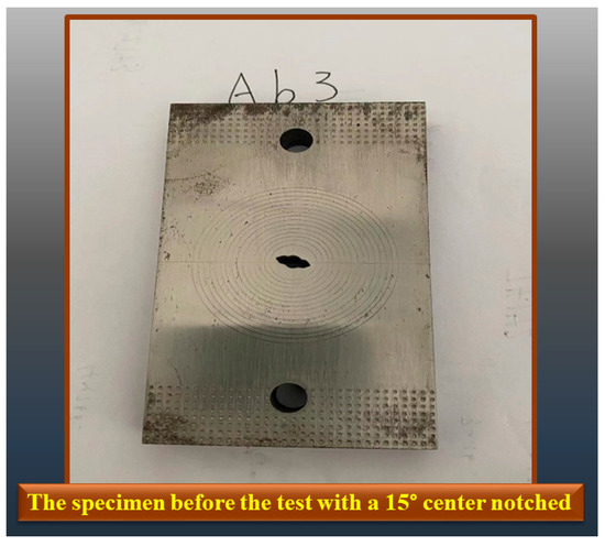
Figure 5.
Specimen before performing the multiaxial FCGT test.
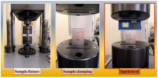
Figure 6.
The installation and debugging process of the specimens within the testing machine in the multiaxial FCGT test.
Once the sample was properly installed and the machine was debugged, a high-speed camera was set up to ensure a clear field of view, allowing for observation of both sides of the sample. To precast the crack, the following calculation [78,79] was performed: K = 10, a = 3, α = 15°, R = 0.1.
The calculated values were as follows:
Pmax = 37,025 N and Pmin = 3703 N
Static load = 20,364 N and Dynamic load = 16,661 N
The test was run for 30,000 to 50,000 cycles based on these conditions. If no crack appeared, the original K value was increased by 10%. The new calculated values were:
Pmax = 40,728 N and Pmin = 4073 N
Static load = 22,400 N, Dynamic load = 18,328 N
The process was repeated following the above requirements until the crack was prefabricated to 1 mm. For the threshold test, R = −1 and the initial crack length (a) = 4 mm, which included the prefabricated crack of 1 mm. Figure 7 displays the specimen after the completion of the multiaxial FCGT test.
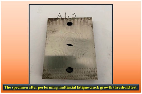
Figure 7.
Specimen after the multiaxial FCGT test.
The results of the multiaxial FCGT tests are presented in Table 5. It can be observed that as the stress intensity factor range (∆K) decreases, the number of cycles (N) increases exponentially. For ∆K = 11 MPa.m0.5, N = 122,500 cycles, whereas for ∆K = 6 MPa.m0.5, N = 11,536,600 cycles, indicating a ninety-four-fold increase. This exponential trend demonstrates the sensitivity of D2 wheel steel to changes in the applied ∆K and highlights the importance of operating below the FCGT to maximize fatigue life. Of the ∆K values tested, 6 MPa.m0.5 resulted in the highest number of cycles before failure, with 11,536,600 cycles recorded. This indicates that 6 MPa.m0.5 is below the FCGT for D2 wheel steel under multiaxial loading conditions and that wheelsets operating below this threshold should have a significantly extended service life. The extended fatigue life associated with lower ∆K values is critical for ensuring the safe operation of high-speed trains over long distances and timeframes. For ∆K values of 9.5 MPa.m0.5 and above, the number of cycles was observed to increase relatively gradually, whereas for ∆K values between 9 MPa.m0.5 and 6 MPa.m0.5, the number of cycles increased sharply, by over an order of magnitude. This sudden change in slope suggests that the fatigue crack growth threshold for D2 wheel steel under multiaxial loading conditions lies between 9 MPa.m0.5 and 6 MPa.m0.5. Below this threshold, crack growth is substantially slowed, resulting in the observed exponential increase in N. This finding has important implications for the design of future high-speed train wheelsets made from D2 wheel steel. The results showed that as the stress intensity factor (∆K) decreased from 11 MPa.m0.5 to 6 MPa.m0.5, the fatigue life of D2 wheel steel specimen increased significantly under multiaxial loading conditions. This highlights that the FCGT of D2 wheel steel lay between 9 MPa.m0.5 to 6 MPa.m0.5. Below 6 MPa.m0.5, the crack growth rate decreased sharply, leading to longer fatigue life. The sudden change in slope from gradual to exponential increase in fatigue life indicates the existence of fatigue crack growth threshold for D2 wheel steel. This highlights the importance of designing the wheelset to operate below the fatigue crack growth threshold value in order to achieve maximum fatigue life and ensure the safety of high-speed train operations.
Table 5.
The results obtained from the multiaxial fatigue crack growth threshold test.
The findings of this investigation are in line with and expand upon the existing research concerning the high-cycle fatigue characteristics of D2 wheel steel. For instance, Liu et al. [80] established that pre-wearing under dry conditions can augment the rolling contact fatigue life of D2 wheel steel by modifying the microstructure and surface roughness. Similarly, this study observed that the crack propagation rate in uniaxial FCGT tests decreased with an increase in the cycle count as the surface roughness intensified, indicating an improvement in the fatigue resistance. Liu et al. [81] reported that the original microstructure of D2 wheel steel has a significant impact on its rolling contact fatigue properties, with tempered sorbite showing better performance than lamellar pearlite. In parallel, this study discovered differences in the crack propagation mechanisms between the uniaxial and multiaxial FCGT tests, which could be attributed to variations in the microstructure and properties at distinct locations. Finally, Kang et al. [82] estimated the fatigue strength of rails under transverse loading and found it to be higher than under vertical loading. This study determined the fatigue crack growth threshold for D2 wheel steel to be between 6–9 MPa.m0.5 under multiaxial loading, which induces both transverse and normal stresses. Overall, this research adds to the existing knowledge by providing further insights into the high-cycle fatigue behavior of D2 wheel steel under complex loading conditions relevant to railway wheelset applications.
3.3. SEM Analysis
Scanning electron microscopy (SEM) is a powerful imaging technique that allows for high-resolution visualization of a sample’s surface. SEM images provide details about a sample’s topography, morphology, and composition. These images are produced by scanning a focused electron beam over the sample’s surface, and detecting the electrons that are scattered or emitted from the sample. The result is a high-resolution image that can reveal details at the nanoscale level.
Figure 8 presents four SEM images of the propagated crack in the uniaxial fatigue crack growth threshold tests. Figure 8a,b show the crack at the early stages of the test, where the crack is still relatively soft and has not propagated significantly. Figure 8c,d, on the other hand, show the crack at later stages of the test, where the crack has propagated significantly due to high-cycle fatigue. The SEM images reveal the details of the crack propagation and the damage caused to the material during the test. During the uniaxial FCGT tests, the crack propagation was observed to occur through a combination of fatigue cracking mechanisms, such as crack initiation, crack propagation, and final fracture. The SEM images in Figure 8 show that the crack initially propagates in a straight path, but as the fatigue test progresses, the crack starts to deviate from its original path due to the interaction with the material’s microstructure. This interaction results in the formation of micro-voids and micro-cracks, which can lead to the formation of new cracks and the eventual failure of the material.
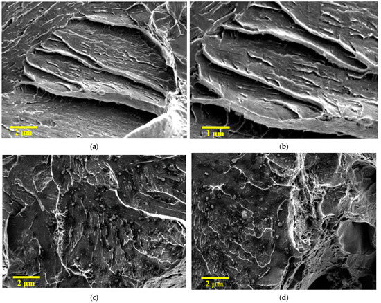
Figure 8.
SEM images of crack area in uniaxial fatigue crack growth threshold tests after (a) 53,028, (b) 208,956, (c) 2,409,483, and (d) 6,074,861 cycles.
Figure 9 also presents four SEM images of the propagated crack in the multiaxial FCGT tests. Figure 9a,b show the crack at the early stages of the test, where the crack is still relatively soft and has not propagated significantly. Figure 9c,d show the crack at later stages of the test, where the crack has propagated significantly due to multiaxial loading. The SEM images reveal the details of the crack propagation and the damage caused to the material during the test. During the multiaxial FCGT tests, the crack propagation was observed to occur through a combination of fatigue cracking mechanisms, such as crack initiation, crack propagation, and final fracture. The SEM images in Figure 9 show that the crack propagation is influenced by the material’s microstructure and the direction of the applied load. The crack tends to propagate along the planes of weakness in the material, such as grain boundaries and interfaces. The interaction between the crack and the microstructure can lead to the formation of complex crack patterns and the eventual failure of the material.
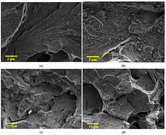
Figure 9.
SEM images of crack area in multiaxial fatigue crack growth threshold test after (a) 125.5 k, (b) 782.2 k, (c) 4085.3 k, and (d) 11,536 k cycles.
A comparison of the two figures reveals some differences in the mechanisms of cracking that occur during the uniaxial FCGT tests and the multiaxial FCGT tests. The uniaxial tests predominantly involve crack propagation through the material’s microstructure, with the crack path deviating due to the interaction with the microstructure. In contrast, the multiaxial tests involve crack propagation along the planes of weakness in the material, with the crack path following the direction of the applied load. The SEM images in both figures reveal the extent of damage caused to the material during the tests, highlighting the importance of SEM analysis in understanding the behavior of materials under stress.
D2 wheel steel is a high-carbon high-chromium tool steel that derives its strength and hardness from the presence of secondary carbide phases, such as chromium carbides, in a tempered martensitic matrix. The interaction of cracks with these hard phases, as well as other microstructural features like grain boundaries and inclusion, are known to influence crack propagation behavior. For example, previous studies have shown that in high-carbon steels, cracks tend to propagate along interfaces between the matrix and hard phases or inclusions. Moreover, cracks in high-alloy tool steels deflect and twist around hard phases, with resulting crack paths that depend strongly on the size, distribution and relative orientation of the phases [80].
In terms of fractographic features, ductile fracture is typically observed in high-strength steels at lower stress intensities (ΔK) within the threshold regime. This is indicated by the presence of dimples and micro-voids on the fracture surface. For D2 wheel steel, it is expected to observe similar signs of ductile fracture at lower ΔK, transitioning to more brittle cleavage features at higher ΔK levels as the material’s toughness decreases with increasing stress. SEM images may reveal micro-voids and transgranular cleavage facets, as reported in other high-alloy steels [83].
4. Conclusions
This study investigated the fatigue behavior and damage mechanisms of D2 wheel steel under high-cycle uniaxial and multiaxial loading conditions. Uniaxial and multiaxial FCGT tests were conducted to determine the fatigue behavior of D2 wheel steel and to understand its crack propagation behavior. Based on the results obtained in this study, several conclusions can be drawn as follows:
- -
- The results of the uniaxial fatigue tests showed that the fatigue crack growth threshold for D2 wheel steel under uniaxial loading conditions ranged between 8–9 MPa.m0.5. Below this threshold, the crack growth rate decreased sharply, indicating the transition to threshold behavior. The number of cycles increased exponentially with decreasing ΔK, highlighting the sensitivity of D2 wheel steel to applied stress intensity factors in the threshold regime.
- -
- The multiaxial fatigue tests revealed that the FCGT for D2 wheel steel under multiaxial loading conditions ranged between 6–9 MPa.m0.5. A ΔK of 6 MPa.m0.5 resulted in over 1 million cycles without failure, indicating that this value was below the FCGT. The number of cycles sharply increased over 1 order of magnitude between ΔK values of 9 MPa.m0.5 to 6 MPa.m0.5, suggesting that the threshold lay within this range.
- -
- SEM analysis revealed differences in the crack propagation mechanisms between the uniaxial and multiaxial fatigue tests. In the uniaxial tests, the crack path deviated from its initial direction due to interactions with the microstructure. In the multiaxial tests, the crack propagated preferentially along planes of weakness in the material, following the loading direction. The analysis highlights the role of loading conditions in crack evolution.
- -
- The findings of this study may provide valuable insights into the fatigue behavior and damage mechanisms of D2 wheel steel under different loading conditions. The study determined the FCGT of D2 wheel steel and revealed how cracks initiate and propagate in D2 wheel steel under uniaxial and multiaxial loading. These insights can facilitate the development of safer and more reliable D2 wheel steel for high-speed rail applications. Future studies should focus on investigating the role of microstructure on the fatigue behavior of D2 wheel steel. Research can examine the effects of grain size, inclusion distribution and morphology, and material processing on crack initiation and growth. A deeper understanding of how microstructure influences fatigue can enable further optimization of D2 wheel steel for high-cycle applications. Furthermore, investigations of the behavior of D2 wheel steel under spectrum loading and variable amplitude loading conditions experienced in service can provide a more comprehensive understanding of the material’s damage evolution and failure mechanisms.
- -
- Finally, the results of this study may have practical implications for the railway industry. The determination of the fatigue crack growth threshold of D2 wheel steel may enable the optimization of wheelset designs to operate below the threshold and achieve maximum fatigue life, ultimately improving the safety and reliability of high-speed trains over long operational periods. Moreover, understanding the influence of microstructure and loading conditions on crack initiation and propagation in D2 wheel steel may inform processing and manufacturing techniques to produce materials with superior fatigue performance. Therefore, the findings of this study may provide a foundation for developing enhanced wheel steels and more durable wheelset designs to address issues such as rolling contact fatigue and rim cracking, thereby contributing to the advancement of the railway industry.
Author Contributions
Author Contributions: S.L. and Y.Z. contributed equally to this work. Conceptualization: S.L. and Y.Z. Methodology: S.L. and Y.Z. Validation: S.L. and Y.Z. Formal Analysis: S.L. and Y.Z. Investigation: S.L. and Y.Z. Writing—Original Draft Preparation: S.L. Writing—Review and Editing: Y.Z. Visualization: S.L. and Y.Z. All authors have read and agreed to the published version of the manuscript.
Funding
This research received no external funding.
Data Availability Statement
The article includes the datasets that support the findings and conclusions of this study.
Conflicts of Interest
The authors declare that they have no known conflict of interest, including financial or personal relationships that could have influenced the work reported in this paper.
References
- Ruijie, Z.; Chunlei, Z.; Bo, L.; Xubiao, W.; Xiaofeng, L.; Yanguo, L.; Fucheng, Z. Research progress on rolling contact fatigue damage of bainitic rail steel. Eng. Fail. Anal. 2023, 143, 106875. [Google Scholar] [CrossRef]
- Xue, F. Investigation of rolling wheel–rail contact using an elaborate numerical simulation. Proc. Inst. Mech. Eng. Part F J. Rail Rapid Transit 2020, 234, 1198–1209. [Google Scholar] [CrossRef]
- He, C.; Zou, G.; Gan, Y.; Ye, R.; Zhai, Y.; Liu, J. Analysing the rolling contact damage behavior of a high-speed wheel tread—A case study. Wear 2023, 522, 204677. [Google Scholar] [CrossRef]
- Barke, D.W.; Chiu, W.K. A Review of the Effects of Out-Of-Round Wheels on Track and Vehicle Components. Proc. Inst. Mech. Eng. Part F J. Rail Rapid Transit 2005, 219, 151–175. [Google Scholar] [CrossRef]
- Giannakopoulos, A.; Lindley, T.; Suresh, S. Aspects of equivalence between contact mechanics and fracture mechanics: Theoretical connections and a life-prediction methodology for fretting-fatigue. Acta Mater. 1998, 46, 2955–2968. [Google Scholar] [CrossRef]
- Guo, K.; Gou, G.; Lv, H.; Shan, M. Jointing of CFRP/5083 Aluminum Alloy by Induction Brazing: Processing, Connecting Mechanism, and Fatigue Performance. Coatings 2022, 12, 1559. [Google Scholar] [CrossRef]
- He, J.-C.; Zhu, S.-P.; Luo, C.; Niu, X.; Wang, Q. Size effect in fatigue modelling of defective materials: Application of the calibrated weakest-link theory. Int. J. Fatigue 2022, 165, 10721. [Google Scholar] [CrossRef]
- Niu, X.; Zhu, S.-P.; He, J.-C.; Liao, D.; Correia, J.A.; Berto, F.; Wang, Q. Defect tolerant fatigue assessment of AM materials: Size effect and probabilistic prospects. Int. J. Fatigue 2022, 160, 106884. [Google Scholar] [CrossRef]
- Nejad, R.M.; Farhangdoost, K.; Shariati, M. Numerical study on fatigue crack growth in railway wheels under the influence of residual stresses. Eng. Fail. Anal. 2015, 52, 75–89. [Google Scholar] [CrossRef]
- Nejad, R.M. Using three-dimensional finite element analysis for simulation of residual stresses in railway wheels. Eng. Fail. Anal. 2014, 45, 449–455. [Google Scholar] [CrossRef]
- Suetrong, C.; Uthaisangsuk, V. Investigations of fatigue crack propagation in ER8 railway wheel steel with varying microstructures. Mater. Sci. Eng. A 2022, 840, 142980. [Google Scholar] [CrossRef]
- Lisowski, F.; Lisowski, E. Optimization of ER8 and 42CrMo4 Steel Rail Wheel for Road–Rail Vehicles. Appl. Sci. 2020, 10, 4717. [Google Scholar] [CrossRef]
- Costa, P.; Nwawe, R.; Soares, H.; Reis, L.; Freitas, M.; Chen, Y.; Montalvão, D. Review of Multiaxial Testing for Very High Cycle Fatigue: From ‘Conventional’ to Ultrasonic Machines. Machines 2020, 8, 25. [Google Scholar] [CrossRef]
- Li, X.-K.; Zhu, S.-P.; Liao, D.; Correia, J.A.; Berto, F.; Wang, Q. Probabilistic fatigue modelling of metallic materials under notch and size effect using the weakest link theory. Int. J. Fatigue 2022, 159, 106788. [Google Scholar] [CrossRef]
- Zhang, P.; Gao, Y.; Liu, Z.; Zhang, S.; Wang, S.; Lin, Z. Effect of cutting parameters on the corrosion resistance of 7A04 aluminum alloy in high speed cutting. Vacuum 2023, 212, 111968. [Google Scholar] [CrossRef]
- Zhu, T.; Ding, H.; Wang, C.; Liu, Y.; Xiao, S.; Yang, G.; Yang, B. Parameters Calibration of the GISSMO Failure Model for SUS301L-MT. Chin. J. Mech. Eng. 2023, 36, 20. [Google Scholar] [CrossRef]
- Dai, Z.; Xie, J.; Jiang, M. A coupled peridynamics–smoothed particle hydrodynamics model for fracture analysis of fluid–structure interactions. Ocean Eng. 2023, 279, 114582. [Google Scholar] [CrossRef]
- Liu, Y.; Li, J.; Lin, G. Seismic performance of advanced three-dimensional base-isolated nuclear structures in complex-layered sites. Eng. Struct. 2023, 289, 116247. [Google Scholar] [CrossRef]
- Zhang, S.; Han, B.; Zhang, T.; Chen, Y.; Xie, J.; Shen, Y.; Huang, L.; Qin, X.; Wu, Y.; Pu, K. High-temperature solid particle erosion characteristics and damage mechanism of AlxCoCrFeNiSi high-entropy alloy coatings prepared by laser cladding. Intermetallics 2023, 159, 107939. [Google Scholar] [CrossRef]
- Ekberg, A. Fatigue of Railway Wheels, Wheel–Rail Interface Handbook; Elsevier: Amsterdam, The Netherlands, 2009; pp. 211–244. [Google Scholar]
- Deng, X.; Qian, Z.; Li, Z.; Dollevoet, R. Investigation of the formation of corrugation-induced rail squats based on extensive field monitoring. Int. J. Fatigue 2018, 112, 94–105. [Google Scholar] [CrossRef]
- Bendikiene, R.; Bahdanovich, A.; Cesnavicius, R.; Ciuplys, A.; Grigas, V.; Jutas, A.; Marmysh, D.; Nasan, A.; Shemet, L.; Sherbakov, S.; et al. Tribo-fatigue Behavior of Austempered Ductile Iron MoNiCa as New Structural Material for Rail-wheel System. Mater. Sci. 2020, 26, 432–437. [Google Scholar] [CrossRef]
- Xu, J.; Wang, K.; Ma, Q.; Li, H.; Wang, P.; Chen, R.; Qian, Y.; Zeng, D. Study on acoustic emission properties and crack growth rate identification of rail steels under different fatigue loading conditions. Int. J. Fatigue 2023, 172, 107638. [Google Scholar] [CrossRef]
- Sun, Q.; Chen, C.; Liu, X. Comparative study of stator current-based and vibration-based methods for railway traction motor bearing cage fault diagnosis at high-speed condition. Struct. Health Monit. 2023, 22, 978–992. [Google Scholar] [CrossRef]
- Hao, R.-B.; Lu, Z.-Q.; Ding, H.; Chen, L.-Q. Orthogonal six-DOFs vibration isolation with tunable high-static-low-dynamic stiffness: Experiment and analysis. Int. J. Mech. Sci. 2022, 222, 107237. [Google Scholar] [CrossRef]
- Lu, Z.-Q.; Gu, D.-H.; Ding, H.; Lacarbonara, W.; Chen, L.-Q. Nonlinear vibration isolation via a circular ring. Mech. Syst. Signal Process. 2020, 136, 106490. [Google Scholar] [CrossRef]
- Luo, C.; Wang, L.; Xie, Y.; Chen, B. A New Conjugate Gradient Method for Moving Force Identification of Vehicle–Bridge System. J. Vib. Eng. Technol. 2022, 1–18. [Google Scholar] [CrossRef]
- Gu, M.; Cai, X.; Fu, Q.; Li, H.; Wang, X.; Mao, B. Numerical Analysis of Passive Piles under Surcharge Load in Extensively Deep Soft Soil. Buildings 2022, 12, 1988. [Google Scholar] [CrossRef]
- Li, Z.-Z.; Zhu, T.; Xiao, S.-N.; Zhang, J.-K.; Wang, X.-R.; Ding, H.-X. Simulation method for train curve derailment collision and the effect of curve radius on collision response. Proc. Inst. Mech. Eng. Part F J. Rail Rapid Transit 2023, 09544097231154313. [Google Scholar] [CrossRef]
- Yang, Y.; Lin, B.; Zhang, W. Experimental and numerical investigation of an arch–beam joint for an arch bridge. Arch. Civ. Mech. Eng. 2023, 23, 101. [Google Scholar] [CrossRef]
- Arslan, M.A.; Kayabaşı, O. 3-D Rail–Wheel contact analysis using FEA. Adv. Eng. Softw. 2012, 45, 325–331. [Google Scholar] [CrossRef]
- Kwon, S.-J.; Seo, J.-W.; Jun, H.-K.; Lee, D.-H. Damage evaluation regarding to contact zones of high-speed train wheel subjected to thermal fatigue. Eng. Fail. Anal. 2015, 55, 327–342. [Google Scholar] [CrossRef]
- Liu, C.; Cui, J.; Zhang, Z.; Liu, H.; Huang, X.; Zhang, C. The role of TBM asymmetric tail-grouting on surface settlement in coarse-grained soils of urban area: Field tests and FEA modelling. Tunn. Undergr. Space Technol. 2021, 111, 103857. [Google Scholar] [CrossRef]
- Jiang, J.; Ye, M.; Chen, L.; Zhu, Z.; Wu, M. Study on Static Strength of Q690 Built-up K-Joints under Axial Loads. In Structures; Elsevier: Amsterdam, The Netherlands, 2023; pp. 760–775. [Google Scholar]
- Xiao, X.; Zhang, Q.; Zheng, J.; Li, Z. Analytical model for the nonlinear buckling responses of the confined polyhedral FGP-GPLs lining subjected to crown point loading. Eng. Struct. 2023, 282, 115780. [Google Scholar] [CrossRef]
- Zhai, S.-Y.; Lyu, Y.-F.; Cao, K.; Li, G.-Q.; Wang, W.-Y.; Chen, C. Seismic behavior of an innovative bolted connection with dual-slot hole for modular steel buildings. Eng. Struct. 2023, 279, 115619. [Google Scholar] [CrossRef]
- Bosso, N.; Cantone, L.; Falcitelli, G.; Gjini, R.; Magelli, M.; Nigro, F.; Ossola, E.; Zampieri, N. Simulation of the thermo-mechanical behaviour of tread braked railway wheels by means of a 2D finite element model. Tribol. Int. 2023, 178, 108074. [Google Scholar] [CrossRef]
- Hong, H.; Kim, M.; Lee, H.; Jeong, N.; Moon, H.; Lee, E.; Kim, H.; Suh, M.; Chung, J.; Lee, J. The thermo-mechanical behavior of brake discs for high-speed railway vehicles. J. Mech. Sci. Technol. 2019, 33, 1711–1721. [Google Scholar] [CrossRef]
- Magelli, M. Development of a 2D finite element model for the investigation of the tread braked railway wheels thermo-mechanical behaviour. IOP Conf. Ser. Mater. Sci. Eng. 2022, 1214, 012041. [Google Scholar] [CrossRef]
- Deressa, K.T.; Ambie, D.A. Thermal Load Simulations in Railway Disc Brake: A Systematic Review of Modelling Temperature, Stress and Fatigue. Arch. Comput. Methods Eng. 2022, 29, 2271–2283. [Google Scholar] [CrossRef]
- Radu, S.M.; Popescu, F.D.; Andraș, A.; Virág, Z.; Brînaș, I.; Draica, M.-I. A Thermo-Mechanical Stress Based Fatigue Life Evaluation of a Mine Hoist Drum Brake System Using COMSOL Multiphysics. Materials 2022, 15, 6558. [Google Scholar] [CrossRef] [PubMed]
- Jiang, L.; Jiang, Y.-L.; Liang, Y.; Nan, S.; Ding, Y.-D. Thermal analysis for brake disks of SiC/6061 Al alloy co-continuous composite for CRH3 during emergency braking considering airflow cooling. Trans. Nonferrous Met. Soc. China 2012, 22, 2783–2791. [Google Scholar] [CrossRef]
- Liu, M.; Wang, J.; Zhu, H.; Krajnovic, S.; Zhang, Y.; Gao, G. A numerical study on water spray from wheel of high-speed train. J. Wind. Eng. Ind. Aerodyn. 2020, 197, 104086. [Google Scholar] [CrossRef]
- Chang, S.; Pyun, Y.-S.; Amanov, A. Wear Enhancement of Wheel-Rail Interaction by Ultrasonic Nanocrystalline Surface Modification Technique. Materials 2017, 10, 188. [Google Scholar] [CrossRef] [PubMed]
- Song, J.; Luo, S.; Liang, X.; Cao, Z.; Zhao, W.; Pu, C.; He, W. Rolling contact fatigue and damage characteristic of AISI 9310 steel with pre-laser shock peening treatment. Int. J. Fatigue 2022, 155, 106588. [Google Scholar] [CrossRef]
- Tian, Y.; Tan, Z.; Wang, J.; Wang, R.; Liu, Y.; Zhang, M. Experiment and finite element analysis of asymmetrical hardness induced by quenching in railway wheel. Eng. Fail. Anal. 2022, 133, 105959. [Google Scholar] [CrossRef]
- Lingamanaik, S.N.; Chen, B.K. Thermo-mechanical modelling of residual stresses induced by martensitic phase transformation and cooling during quenching of railway wheels. J. Mater. Process. Technol. 2011, 211, 1547–1552. [Google Scholar] [CrossRef]
- Zhang, Q.; Toda-Caraballo, I.; Li, Q.; Han, J.; Han, J.; Zhao, J.; Dai, G. Tension-shear multiaxial fatigue damage behavior of high-speed railway wheel rim steel. Int. J. Fatigue 2020, 133, 105416. [Google Scholar] [CrossRef]
- Cong, T.; Han, J.; Hong, Y.; Domblesky, J.P.; Liu, X. Shattered rim and shelling of high-speed railway wheels in the very-high-cycle fatigue regime under rolling contact loading. Eng. Fail. Anal. 2019, 97, 556–567. [Google Scholar] [CrossRef]
- Tunna, J.; Sinclair, J.; Perez, J. A review of wheel wear and rolling contact fatigue. Proc. Inst. Mech. Eng. Part F J. Rail Rapid Transit 2007, 227, 271–289. [Google Scholar] [CrossRef]
- Zhang, S.; Liu, Q.; Spiryagin, M.; Wu, Q.; Ding, H.; Wen, Z.; Wang, W. Gaps, challenges and possible solution for prediction of wheel–rail rolling contact fatigue crack initiation. Railw. Eng. Sci. 2023, 1–26. [Google Scholar] [CrossRef]
- Akama, M. Development of Finite Element Model for Analysis of Rolling Contact Fatigue Cracks in Wheel/Rail Systems. Q. Rep. RTRI 2007, 48, 8–14. [Google Scholar] [CrossRef]
- Chaimongkon, T.; Panich, S.; Uthaisangsuk, V. Anisotropic fracture forming limit curve and its applications for sheet metal forming with complex strain paths of aluminum sheet. Int. J. Adv. Manuf. Technol. 2021, 115, 3553–3577. [Google Scholar] [CrossRef]
- Ekberg, A.; Åkesson, B.; Kabo, E. Wheel/rail rolling contact fatigue–Probe, predict, prevent. Wear 2014, 314, 2–12. [Google Scholar] [CrossRef]
- Yong, N.; Kegang, L.; Deke, L.; Xianglong, L.; Shoujian, P. Experimental Investigation on Shock Mechanical Properties of Red Sandstone under Preloaded 3D Static Stresses. J. Eng. Sci. Technol. Rev. 2015, 8, 205–211. [Google Scholar] [CrossRef]
- Arfa, E.; Magnier, V.; Dufrénoy, P.; de Saxcé, G. Multi-scale Contact Approach Considering Material Heterogeneity and Wear. Tribol. Lett. 2021, 69, 135. [Google Scholar] [CrossRef]
- Sabato, A.; Niezrecki, C. Feasibility of digital image correlation for railroad tie inspection and ballast support assessment. Measurement 2017, 103, 93–105. [Google Scholar] [CrossRef]
- Nikas, D.; Ahlström, J.; Malakizadi, A. Mechanical properties and fatigue behaviour of railway wheel steels as influenced by mechanical and thermal loadings. Wear 2016, 366, 407–415. [Google Scholar] [CrossRef]
- Banerjee, U. Modeling damage mechanics of railway tracks to evolve control strategies for derailment prevention. Multidiscip. Model. Mater. Struct. 2013, 9, 341–358. [Google Scholar] [CrossRef]
- Ostash, O.P.; Anofriev, V.H.; Andreiko, I.; Muradyan, L.A.; Kulyk, V. On the concept of selection of steels for high-strength railroad wheels. Mater. Sci. 2013, 48, 697–703. [Google Scholar] [CrossRef]
- Ostash, O.; Kulyk, V.; Lenkovskiy, T.; Duriagina, Z.; Vira, V.; Tepla, T. Relationships between the fatigue crack growth resistance characteristics of a steel and the tread surface damage of railway wheel. Arch. Mater. Sci. Eng. 2018, 2, 49–55. [Google Scholar] [CrossRef]
- Gowtham, V.; Ranganathan, A.S.; Satish, S.; Alexis, S.J.; Kumar, S.S. Fatigue based design and analysis of wheel hub for Student formula car by Simulation Approach. IOP Conf. Ser. Mater. Sci. Eng. 2016, 149, 012128. [Google Scholar] [CrossRef]
- Suchý, L.; Hasse, A. Fatigue of multiaxially loaded shaft-hub connection under different load parameters. In Proceedings of the 8th International Conference on Fracture, Fatigue and Wear: FFW 2020, August 26–27 2020; Springer: Berlin/Heidelberg, Germany, 2021; pp. 473–487. [Google Scholar]
- Mangardich, D.; Abrari, F.; Fawaz, Z. A fracture mechanics based approach for the fretting fatigue of aircraft engine fan dovetail attachments. Int. J. Fatigue 2019, 129, 105213. [Google Scholar] [CrossRef]
- Venkatesh, P.; Kattimani, M.A.; Uddin, M.S.; Uddin, M.M. Evaluation of Fatigue Life of Nickel Alloy for Gas Turbines Hub. Evaluation 2022, 10, 2769–2774. [Google Scholar]
- Fu, Q.; Gu, M.; Yuan, J.; Lin, Y. Experimental Study on Vibration Velocity of Piled Raft Supported Embankment and Foundation for Ballastless High Speed Railway. Buildings 2022, 12, 1982. [Google Scholar] [CrossRef]
- Xiao, S.; Cao, Y.; Wu, G.; Guo, Y.; Gao, G.; Chen, S.; Liu, P.; Wang, Z.; Li, P.; Yu, J. Influence of the distributed grounding layout for intercity trains on the ‘train-rail’circumflux. IEEE Trans. Circuits Syst. II Exp. Briefs 2023, 70, 1194–1198. [Google Scholar] [CrossRef]
- Zhang, C.; Kordestani, H.; Shadabfar, M. A combined review of vibration control strategies for high-speed trains and railway infrastructures: Challenges and solutions. J. Low Freq. Noise Vib. Act. Control. 2023, 42, 272–291. [Google Scholar] [CrossRef]
- Bai, X.; Shi, H.; Zhang, K.; Zhang, X.; Wu, Y. Effect of the fit clearance between ceramic outer ring and steel pedestal on the sound radiation of full ceramic ball bearing system. J. Sound Vib. 2022, 529, 116967. [Google Scholar] [CrossRef]
- Fu, Z.; Yang, B.; Shan, M.; Li, T.; Zhu, Z.; Ma, C.; Zhang, X.; Gou, G.; Wang, Z.; Gao, W. Hydrogen embrittlement behavior of SUS301L-MT stainless steel laser-arc hybrid welded joint localized zones. Corros. Sci. 2020, 164, 108337. [Google Scholar] [CrossRef]
- Zhu, Q.; Chen, J.; Gou, G.; Chen, H.; Li, P. Ameliorated longitudinal critically refracted—Attenuation velocity method for welding residual stress measurement. J. Mater. Process. Technol. 2017, 246, 267–275. [Google Scholar] [CrossRef]
- Rackwitz, J.; Yu, Q.; Yang, Y.; Laplanche, G.; George, E.P.; Minor, A.M.; Ritchie, R.O. Effects of cryogenic temperature and grain size on fatigue-crack propagation in the medium-entropy CrCoNi alloy. Acta Mater. 2020, 200, 351–365. [Google Scholar] [CrossRef]
- Sausto, F.; Carrion, P.; Shamsaei, N.; Beretta, S. Fatigue failure mechanisms for AlSi10Mg manufactured by L-PBF under axial and torsional loads: The role of defects and residual stresses. Int. J. Fatigue 2022, 162, 106903. [Google Scholar] [CrossRef]
- Wu, S.; Li, C.; Luo, Y.; Zhang, H.; Kang, G. A uniaxial tensile behavior based fatigue crack growth model. Int. J. Fatigue 2020, 131, 105324. [Google Scholar] [CrossRef]
- Benedetti, M.; Santus, C. Mean stress and plasticity effect prediction on notch fatigue and crack growth threshold, combining the theory of critical distances and multiaxial fatigue criteria. Fatigue Fract. Eng. Mater. Struct. 2019, 42, 1228–1246. [Google Scholar] [CrossRef]
- D’elia, G.; Mucchi, E.; Dalpiaz, G. A novel methodology for dynamic response maximisation in multi-axis accelerated random fatigue testing. Mech. Syst. Signal Process. 2022, 181, 109491. [Google Scholar] [CrossRef]
- Wang, Y.; Zhang, X.; Su, Z.; Yao, W. Multiaxial fatigue life prediction based on single defect for additively manufactured 316L. Int. J. Fatigue 2022, 163, 107101. [Google Scholar] [CrossRef]
- Bold, P. Multiaxial Fatigue Crack Growth in Rail Steel. Ph.D. Thesis, University of Sheffield, Sheffield, UK, 1990. [Google Scholar]
- Engin, Z. Evaluation of Several Multiaxial High Cycle Fatigue Endurance Criteria. Master’s Thesis, Middle East Technical University, Ankara, Turkey, 2018. [Google Scholar]
- Liu, C.-P.; Liu, P.-T.; Pan, J.-Z.; Chen, C.-H.; Ren, R.-M. Effect of pre-wear on the rolling contact fatigue property of D2 wheel steel. Wear 2020, 442, 203154. [Google Scholar] [CrossRef]
- Liu, C.-P.; Pan, J.-Z.; Liu, P.-T.; Ren, R.-M.; Zhao, X.-J. Influence of original microstructure on rolling contact fatigue property of D2 wheel steel. Wear 2020, 456, 203380. [Google Scholar] [CrossRef]
- Kang, C.; Schneider, S.; Wenner, M.; Marx, S. Experimental investigation on the fatigue behaviour of rails in the transverse direction. Constr. Build. Mater. 2021, 272, 121666. [Google Scholar] [CrossRef]
- Tokaji, K.; Ko, H.-N.; Nakajima, M.; Itoga, H. Effects of humidity on crack initiation mechanism and associated S–N characteristics in very high strength steels. Mater. Sci. Eng. A 2003, 345, 197–206. [Google Scholar] [CrossRef]


Disclaimer/Publisher’s Note: The statements, opinions and data contained in all publications are solely those of the individual author(s) and contributor(s) and not of MDPI and/or the editor(s). MDPI and/or the editor(s) disclaim responsibility for any injury to people or property resulting from any ideas, methods, instructions or products referred to in the content. |
© 2023 by the authors. Licensee MDPI, Basel, Switzerland. This article is an open access article distributed under the terms and conditions of the Creative Commons Attribution (CC BY) license (https://creativecommons.org/licenses/by/4.0/).