Abstract
In this study, we investigate how changing the nitrogen flow rate, the length of time during deposition, and the intensity of pressure have an impact on the resulting chromium oxynitride coatings. Depending on the sputtering conditions, the X-ray diffraction analyses reveal different textures in the Cr2O3 and Cr2N phases. Films deposited with varying nitrogen flow rates and deposition durations experience compressive strains, whereas films produced with varying sputtering pressures witness tensile stresses. Film surface energies and contact angles were measured with a contact angle goniometer. Because of their hydrophobic properties, chromium oxynitride coatings may find use as water-repellent, self-cleaning surfaces. Chromium oxynitride films’ absorption and transmission curves were recorded using a UV-Vis-NIR spectrophotometer. The band gap of chromium oxynitride coatings reduces with a rise in the flow of nitrogen and sputtering time but widens with increasing deposition pressure.
1. Introduction
Better tribological qualities and operational advantages have shifted the focus of many researchers away from the original binary coatings (CrNx and CrCx) toward poly-phase and multi-component (CrCN, CrTiAlN, CrON, CrAlN, etc.) coatings [1,2,3,4,5,6,7]. Oxynitrides and nitrides of d-, p-, and f-block elements have attracted increasing attention during the past two decades [8]. Gas turbine rotor blades, cutting tools, and other commercial uses have recently found transition metal oxynitrides to be technologically even more enticing due to their improved performance as diffusion barriers [9,10].
Chromium oxynitride belongs to this group of transition metal oxynitrides, with it having characteristics similar to both chromium nitride and chromium oxide. Thin coatings of chromium nitride and oxynitride were deposited by J. Du et al. [11] using a cathodic arc evaporation technique. They investigated how the pressures of oxygen affected the hardness, structure, and thermal properties of the materials as well as the residual stress and texture. T. Wierzchon et al. [12] investigated the structural and corrosion resistance properties of chromium oxynitride, nitride, and oxide layers developed on steels by employing electrochemical chromium deposition in conjunction with glow-discharge-assisted oxynitriding, nitriding, and oxidizing methods. C. Nunes et al. [13] developed graded selective titanium oxynitride and chromium coatings using magnetron sputtering to increase the effectiveness of thermal solar collectors. W. Y. Ho et al. [14] used a cathodic arc deposition technique to form a chromium oxynitride/CrN double-layered coating on tool steel substrates. The coatings were analyzed for corrosion behavior, phase structure, and chemical structure. Using reactive cathodic arc physical vapor deposition, M. Urgen et al. [15] formed Cr-O-N, Cr-O, and CrN coatings on high-speed steel substrates with varying oxygen concentrations. The friction and wear characteristics of these coatings were studied over a temperature range of 25 to 100 °C.
Since the invention of the so-called “lotus effect” a decade ago, there has been a surge of interest in both theoretical and practical uses of water-repellent surfaces that defy conventional explanations. Its self-cleaning properties make water-repellent surfaces useful in many contexts, including avoiding the adherence and contamination of water, snow, or dust to windows and antennas, lowering drag friction, making fabrics and utensils stain resistant, and so on [16,17,18,19,20]. When designing water-repellent surfaces, the contact angle and surface energy play a crucial role.
The majority of the papers on chromium oxynitride films are mostly concentrated on its corrosion/oxidation-resistant, structural, mechanical, and wear-resistant properties. The wettability study of chromium oxynitride films such as surface energy and contact angle properties is an unexplored area, and so far, we have been unable to find such studies in the literature. The optical properties exploration of chromium oxynitride coatings such as transmission, refractive index, and band gap is also very rare in the literature and is the area that can potentially explore the use of these films as semi-transparent/transparent, wear/corrosion-resistant protective coatings.
Magnetron sputtering has emerged as a popular method for Cr-based coatings because of the good adhesion and mechanical properties of the coatings [21]. The sputtering process involves various processing parameters that affect the final characteristics of the developed films. For the purpose of developing the chromium oxynitride coatings mentioned in the literature, argon was used as an inert gas combined with the reactive gases oxygen and nitrogen. Furthermore, we were unable to identify any published works that discussed the impact that varying deposition conditions, such as the gas flow of nitrogen, sputtering duration, and deposition pressure, have on chromium oxynitride coatings.
Therefore, in the current research, a systematic examination of the impact of altering deposition conditions as indicated above on the wettability and optical characteristics of chromium oxynitride coatings prepared by reactive magnetron sputtering is reported as investigations regarding these parameters and properties are rare in the literature. In order to develop chromium oxynitride films using reactive magnetron sputtering, we substituted helium for argon as the inert gas. The major reason is that no literature examples stating the use of helium could be found, and also, it has higher ionization potential, so it can easily ionize oxygen, whose flow rate is kept very low as compared to other types of reactive gas nitrogen, which is used during deposition due to the higher reactivity of the former. Additionally, as described in previous studies, the titanium and zirconium oxynitride films formed in helium exhibit superior hydrophobic characteristics in comparison to argon [22]. By employing argon as an inert gas for fabricating chromium oxide thin films, K. Patel et al. were able to attain a maximum contact angle of 98.4° [23]. A maximum contact angle of 94.1° was attained in previously published research on co-sputtered titanium and chromium oxynitride thin films [22]. The wettability studies of chromium oxynitride coatings, such as contact angle measurements and surface energy, are not widely accessible in the literature; therefore, this research made an attempt to achieve a higher hydrophobicity by utilizing helium as inert gas. Optical studies of chromium oxynitride films are also very few in the literature. The optical characteristics of chromium oxynitride films, including transmission, refractive index, and band gap, were investigated using a Uv-Vis-NIR spectrophotometer, and a contact angle measurement device was employed to determine the surface energy as well as the contact angle of the coatings.
2. Materials and Methods
Chromium oxynitride nanocrystalline thin films were developed on glass substrates using radio frequency magnetron sputtering in a specially constructed chamber (Excel Instruments, Palghar, Maharashtra, India). The sputtering target utilized was 99.97% pure chromium, and it was 2” in diameter and 5 mm thick. Helium and reactive gases like nitrogen and oxygen with a purity of 99.9% were employed to develop the chromium oxynitride coatings. Mass flow controllers and capacitance manometers (MKS) were used to regulate and monitor the gas mixture proportions. The entire deposition process was carried out at a temperature of 500 °C. For all sets of deposits, the flow of helium and oxygen was held constant at 10 and 1.3 sccm, respectively. Changes were made only to the gas flow of nitrogen, which ranged from 55 to 100 sccm; the chromium oxynitride coatings for these variations were given the names CN55, CN70, CN85, and CN100. The sputtering pressure and duration were both set at 2.0 Pa and 60 min, respectively. Films deposited at different times of 80, 100, 120, and 140 min are designated CT80, CT100, CT120, and CT140, respectively. The sputtering pressure and gas flow of nitrogen were both 2.0 Pa and 55 sccm, respectively. The flow of nitrogen was 55 sccm, the deposition duration was 60 min, and variations in pressure of 4.0, 6.0, and 8.0 Pa resulted in films designated as CP30, CP45, and CP60, respectively.
The X-ray diffractometer (XRD) (D8 Advance, Bruker, Bremen, Germany) was used to estimate stress using the sin2ψ technique and to perform a structural analysis of the nanocrystalline chromium oxynitride films. Atomic force microscopy (Ntegra, NT-MDT, Moscow, Russia) was used to assess the surface morphology of the films. These films underwent elemental analysis by using energy-dispersive X-ray spectroscopy (Quanta 200F, FEI, Eindhoven, The Netherland). In order to determine the contact angle of the coating and its surface energy, wettability investigations were conducted using contact angle measuring equipment (DSA 100 Easy Drop, Kruss, Hamburg, Germany). Using a Surface profilometer (XP-200 Ambios Technology Inc., Santa Cruz, CA, USA), the thicknesses of the samples were measured and analyzed. We used a UV-Vis-NIR spectrophotometer (Varian Cary 5000, Varian Inc., Palo Alto, CA, USA) to determine the optical transparency and absorption of the coatings.
3. Results and Discussion
3.1. Structural Properties
The XRD technique was used to observe the structural and orientation changes in the deposited chromium oxynitride films. Figure 1a–c indicates how the nitrogen gas flow, deposition time, and pressures affect the XRD patterns of the deposited films. When the nitrogen flow is kept at 55 sccm, the developed films demonstrate the emergence of well-oriented (1 0 4) and (1 1 6) peaks of a Cr2O3 phase along with its less intense (0 1 2) and (0 2 4) peaks. The development of a Cr2N phase with a weak crystalline (0 0 2) peak is also seen (Figure 1a). The high nitrogen flow rate as compared to oxygen leads to a greater proportion of sputtered nitrogen atoms, thus favoring the formation of a Cr2N phase. The only time the (1 0 1 0) and (1 1 0) oriented peaks of the Cr2O3 and Cr2N phases are seen is at 70 sccm gas flow of nitrogen along with the peaks of the Cr2O3 and Cr2N phases, which were observed at a 55 sccm gas flow of nitrogen. The presence of these Cr2O3 and Cr2N phases for chromium oxynitride films deposited by different techniques and under various deposition conditions is well supported by the literature [9,24]. When the flow of nitrogen gas is improved to 85 and 100 sccm, the (0 1 2), (1 0 4), (0 2 4), and (1 1 6) peaks of the Cr2O3 phase are observed.
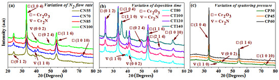
Figure 1.
XRD patterns of chromium oxynitride coatings developed at different (a) nitrogen gas flows, (b) sputtering times, and (c) deposition pressures.
The deposited chromium oxynitride films depict well-oriented (0 1 2), (1 0 4), and (1 1 6) peaks of the Cr2O3 phase along with its weakly crystalline (0 2 4), (2 1 4), and (1 0 10) peaks when the sputtering time is 80 and 100 min (Figure 1b). They also show the presence of less intense (1 1 0) and well crystalline (0 0 2) peaks of the Cr2N phases. The intensity of the (0 1 2) and (0 2 4) peaks of the Cr2O3 phases increases drastically along with the (0 0 2) peak of the Cr2N phase as the sputtering time is kept at 120 min. At the sputtering time of 140 min for the Cr2O3 phase, its (0 1 2) peak becomes less intense than the one observed for 120 min, the (0 2 4) peak almost diminishes, the (1 0 1 0) peak becomes well crystalline, and the evolution of a newly oriented well intense (1 1 0) peak is observed. Moreover, for the Cr2N phase, the intensity of its (0 0 2) peak declines sharply, whereas that of the (1 1 0) peak increases significantly as compared to the films deposited for 120 min. W. Y. Ho et al. [14] also observed (0 1 2), (1 0 4), (1 1 0), (1 1 3), (0 2 4), (1 1 6), and (2 1 4) peaks of the Cr2O3 phase depending on the flow rate of oxygen. M. Tabbal et. al. [25] observed the presence of various orientations of the Cr2O3 phase depending on the deposition temperature. The extension of deposition time may have provided a sufficient moment to the sputtered atoms, which may have resulted in the facilitation of various orientations of the Cr2O3 and Cr2N phases. Moreover, the deposition temperature is also high (500 °C), which favors the formation of such polycrystalline films. Therefore, it is consistent with the literature that the development of Cr2O3 and Cr2N phases with different orientations may be caused by the increase in time.
When the deposition pressure is kept at 4.0 Pa, well-oriented (1 0 4) and (1 1 6) peaks along with a less intense (1 0 1 0) peak of the Cr2O3 phase are observed (Figure 1c). It also shows the presence of weakly crystalline (1 1 0) and (0 0 2) peaks of the Cr2N phases. When the pressure was elevated to 6.0 and 8.0 Pa, the (1 0 1 0) peak of the Cr2O3 phase along with the (1 1 0) and (0 0 2) peaks of the Cr2N phase disappeared. When the pressure was increased, the (1 0 4) peak of the Cr2O3 phase became more apparent. Table 1 provides a summary of the average crystallite size determined using the Scherrer formula [26]. It is ~12 nm for films deposited at 70 sccm and between 15 to 18 nm as the flow of nitrogen was 55, 85, and 100 sccm. It varies from 17 to 25 nm for chromium oxynitride coatings deposited at different sputtering durations, from 80 to 140 min. The size of the grain grows from 50 to 55 nm, as the deposition pressure is increased from 4.0 to 8.0 Pa. Table 1 displays the elemental and atomic composition of the developed films as measured by energy dispersive X-ray spectroscopy (EDAX). EDAX detected the presence of O, N, and Cr in the Cr2O3 thin films. As can be seen in Figure 1, the evolution of Cr2O3 films may be attributable to changes in chemical composition caused by an increase in nitrogen flow from 55 to 100 sccm. A minor reduction in nitrogen concentration in the Cr2O3 films was observed as the gas flow was increased from 70 to 100 sccm. Common causes of XRD pattern shifts include strain and variations in chemical composition. Y. Yuan et al. noted a similar pattern of declining nitrogen concentration with rising nitrogen gas flow. In addition, they came to the conclusion that even though N atoms were introduced into the films and their contents varied depending on the variation in the nitrogen flow rate, even the O content was higher than the N content. They deposited CrOxNy thin films with a change in nitrogen flow from 5 to 10 sccm, and the nitrogen (at.%) decreased from 26.2 to 10.4. Due to the significant difference in electronegativity between Cr and O, which makes Cr-O bonds simpler to form, the O/Cr ratio was larger than the N/Cr ratio [27]. As the deposition time and pressure were increased, there was a shift in chemical composition, which was also reflected in the structural properties of the deposited thin films.

Table 1.
The calculated parameters of the developed coatings.
Using the method given in detail elsewhere [28,29], we were able to determine the relative textural coefficients of the chromium oxynitride coatings by analyzing the XRD peaks. Figure 2a–c displays the computed relative texture coefficients of the developed chromium oxynitride coatings at different nitrogen flow rates, development times, and deposition pressures. Residual stress in the developed coating was obtained through the XRD technique with the sin2Ψ method described elsewhere [30,31]. Strain and residual stress were calculated using the relative texture coefficient of (1 0 4) for the developed coatings. Figure 3a–c depicts the stress and strain of chromium oxynitride coatings subjected to varying nitrogen flow rates, depositing durations, and sputtering pressures. In a film, the surface energy and strain energy are in a key rivalry, which might determine the film’s preferred orientation. In contrast to strain energy, which grows linearly with film thickness, surface energy is independent of the coating’s thickness [32]. In addition, the films show an orientation that corresponds to the lowest surface energy while they are thin, and the strain energy becomes higher than the surface energy as the film thickness increases [33].
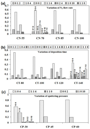
Figure 2.
Relative texture coefficients of chromium oxynitride coatings developed at different (a) nitrogen gas flows, (b) sputtering times, and (c) deposition pressures.
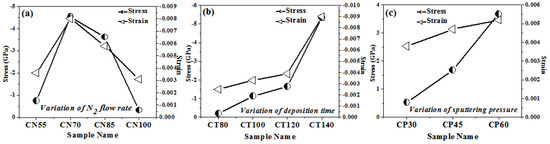
Figure 3.
Stress and strains of chromium oxynitride coatings developed at different (a) nitrogen gas flows, (b) sputtering times, and (c) deposition pressures.
At a nitrogen flow rate of 70 sccm, the measured strain is at the maximum, as shown in Figure 3a. Therefore, this may be the possible reason for the presence of (1 0 1 0) and (1 1 0) oriented peaks of the Cr2O3 and Cr2N phases, respectively, due to higher strain energy. The Cr2O3 and Cr2N phases have nearly identical relative texture coefficients at nitrogen flows of 55, 85, and 100 sccm, indicating that they share the same orientation. When the gas flow is 70 sccm, the thickness fluctuation remains minimal. Therefore, for these cases, the surface energy might be dominant, giving orientations with an almost constant relative texture coefficient, as shown in Figure 2a.
According to published research, ion bombardment can boost coating density and nucleation rates under optimal deposition circumstances, while also decreasing the average size of the grains, providing higher roughness, and influencing the level of defects and orientation in films in a tunable manner [34]. The microstructure becomes denser due to the increased surface mobility of adatoms as the deposition time advances due to an increase in the number of ions bombarding the surface. As a result, as seen in Table 1, the developed chromium oxynitride coatings becomes thicker with time. This increases the strain energy of the deposited films, which may result in the formation of various textures, as shown in Figure 2b when the sputtering time is extended from 80 to 140 min.
The literature reports an inverse relationship between the sputtering pressure and mean free path [35]. When the pressure is elevated from 4.0 to 8.0 Pa, more collisions take place between the sputtered atoms because the mean free path is shorter. Therefore, the number of atoms striking the substrate and causing film deposition may decrease, along with the thickness of the developed coatings. Therefore, this may be the possible reason for the absence of the (1 0 1 0) texture of the Cr2O3 phase along with the (1 1 0) and (0 0 2) textures of the Cr2N phases at a higher sputtering pressure. It may have also resulted in an increase in the (1 0 4) texture and a decline in the (1 1 6) texture of the Cr2O3 phase as shown in Figure 2c. The presence of only the (1 0 4) and (1 1 6) textures of the Cr2O3 phase at a higher sputtering pressure may be due to the fact that these two are the most preferred orientations for the Cr2O3 phase. In addition, the sputtered atoms may agglomerate and expand prior to reaching the substrate as a result of their frequent collisions. In light of this, changes in sputtering pressure may have a greater effect on the average crystallite size of formed chromium oxynitride coatings than changes in nitrogen gas flow and sputtering duration (Table 1).
Several factors, including grain size, morphology, texture, microstructure, etc., contribute to the inherent residual stress in sputtered films. Compressive stresses rise with increasing amounts of reactive gas atoms in the coating, as documented in the literature [36]. This effect continues until the coating is saturated with reactive gas atoms. It has been documented in the literature [37,38] that nitrogen inclusions, particularly at interstitial locations, cause the compressive stress in coatings to rise as the partial pressure of nitrogen rises. Therefore, when the gas flow of nitrogen, which is employed as a reactive gas, increases, so does the number of reactive gas atoms. Figure 3a shows that as the gas flow of nitrogen (reactive gas) is increased from 55 to 70 sccm, the residual stress of the developed coatings increases, with a maximum value at 70 sccm. Furthermore, a rise in gas flow to 85 and 100 sscm causes a decline in the residual stress value as compared to the one observed at 70 sccm. The possible reason may that the formation of well crystalline (1 1 0) and (0 0 2) oriented peaks of the Cr2N phase is observed only at a 70 sccm flow rate, as shown in Figure 1a. The structural variation observed for 55, 85, and 100 sccm nitrogen flow rates is very small, resulting in little difference in the measured stress and strain values. Therefore, the morphological and texture change observed at the 70 sccm nitrogen flow rate may be the possible reason for the higher compressive stress of the developed chromium oxynitride coatings.
In their study of residual stress in metal oxynitride systems, S. Venkataraj et al. [39] hypothesized that high-energy particles, such as reflected neutrals or ions, bombard the growing film with maximum kinetic energy, causing collision cascades in the deposited material and leading to the observed compressive stress of the films. Using an atomic peening method, as described in much detail by F. M. D’heurle et al. [40], this should result in a denser morphology. The measured stresses of chromium oxynitride coatings are compressive and rise with the deposition time (Figure 3b). The high-energy ions produced in the plasma have enough time to grow and stabilize on the substrate, generating different phases and textures, as the sputtering period increases from 80 to 140 min. Additionally, this causes the formed coating to become thicker (Table 1) and creates a dense structure that is depicted by a pattern of well crystalline Cr2O3 and Cr2N phases with distinct textures, as shown in Figure 1b and Figure 2b, respectively. S. B. Amor et al. [41] also noticed that compressive stress increases as the film thickness evolves. As a result, the compressive stress and strain rise with both thickness and development time for chromium oxynitride.
As the mean free route length decreases, the distance over which neutral, unaccelerated particles may move and the path over which ionized particles can be accelerated becomes smaller. According to the literature [36], this causes the particles’ kinetic energy to drop upon impact with the substrates. This would lead to moderate ion bombardment on the substrate in which tensile stress may dominate as reported in the literature [37]. The tensile residual stress grows as the sputtering pressure for developed coatings is increased from 4.0 to 8.0 Pa (Figure 3c). As discussed earlier, with the increase in sputtering pressure, a decrease in the mean free path, deposition rate, and thickness of chromium oxynitride films is observed. This might explain why there is a rise in tensile stress and strain as the deposition pressure is increased from 4.0 to 8.0 Pa.
3.2. Hydrophobic Properties
The 3D AFM images of the developed chromium oxynitride coatings at different flows of nitrogen gas, deposition times, and pressures are depicted in Figure 4a, Figure 4b, and Figure 4c, respectively. Figure 5a–c depicts the change in contact angle values as a function of the nitrogen flow rate, deposition duration, and working pressure for the developed chromium oxynitride coatings. As the flow of nitrogen gas is elevated from 85 to 100 sccm, the roughness of the chromium oxynitride coatings falls from their highest value achieved at 70 sccm. The observed roughness values of the chromium oxynitride coatings at 55, 70, 85, and 100 sccm nitrogen flow rates are 4.7, 5.9, 5.4, and 3.8 nm, respectively (Figure 5a). The height scale of the AFM image determines the roughness value of the developed coatings. It was reported by E. Berasategui et al. that as the gas flow or partial pressure expands, the sputtered species become more likely to self-shadow because of the energy loss they experience from frequent contacts and a shorter mean free path. As a result, the roughness decreases with the increasing partial pressure [42]. S. Han et al. found that increasing the gas flow rate from 25 to 100 sccm reduced the roughness from 0.43 to 0.38 nm. Coating roughness was observed to be influenced by the flow rate and the size of the particles [43,44]. Higher deposition times result in progressively thicker coatings of chromium oxynitride. As the deposition period increases from 80, 100, and 120 to 140 min, the roughness rises from 3.4, 5.2, and 8.7 to 9.8 nm, respectively (Figure 5b). The surface roughness values of 4.1, 4.4, and 4.0 nm were observed at 4.0, 6.0, and 8.0 Pa sputtering pressure for the developed chromium oxynitride coatings (Figure 5c), respectively. A comparable decrease in surface roughness with an increase in pressure was reported by M. Mohammadtaheri et al. They found that when the pressure was increased, the coating thickness of the formed chromium oxide thin film expanded but then reduced. At higher pressures, the average free path of gas molecules decreases, which contributes to the collisions between sputtered atoms and gas molecules [45].
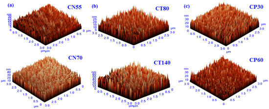
Figure 4.
Three-dimensional AFM images of chromium oxynitride coatings developed at different (a) nitrogen gas flows, (b) sputtering times, and (c) deposition pressures.
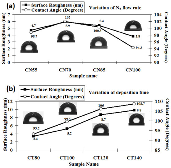
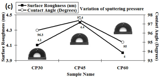
Figure 5.
Surface roughness and contact angle of chromium oxynitride coatings developed at different (a) nitrogen gas flows, (b) sputtering times, and (c) deposition pressures.
Changing the amount of nitrogen flowing through the system from 55 to 70 sccm results in a higher contact angle, reaching a maximum value at 70 sccm, and thereafter shows a declining trend when the gas flow is further elevated to 85 and 100 sccm, respectively (Figure 5a). The maximum value of the contact angle around 102° was observed for the nitrogen flow of 70 sccm. A possible reason may be the higher surface roughness value observed for this case giving a higher contact angle, which varies directly with the roughness of the surface. Using two liquids, water and diiodomethane, the surface energy of the developed coatings was determined using the Owens–Wendt geometric technique and the Wu harmonic approach, which is outlined briefly elsewhere [46]. The surface energy varies inversely with the measured contact angle values, so the lowest surface energy is observed for the maximum contact angle value, which is at a 70 sccm flow rate of nitrogen, as summarized in Table 2. The possible reason for the higher contact angle at the 70 sccm flow rate may be the presence of (1 0 1 0) and (1 1 0) oriented peaks of Cr2O3 and Cr2N phases, respectively, which are only visible at a nitrogen gas flow of 70 sccm, as observed in the XRD graphs.
Table 2.
Calculated surface energies of chromium oxynitride films by the O.W. and Wu methods.
Increasing the deposition time for chromium oxynitride films increases the surface roughness values, which in turn increases the contact angle as the two have a direct relationship. The observed contact angle is 93.2° at a deposition time of 80 min, as shown in Figure 5b. The contact angle rises to 108.7° due to the higher surface roughness of ~9.8 nm, with a further rise in sputtering time to 140 min. The height scale of surface structures plays a critical role in the determination of the contact angle on the surface, as reported in the literature [47,48]. The 3D AFM images demonstrate that the roughness values advance as the deposition duration increases due to an increase in the height scale of the coatings. In addition, both conical and hemispherical asperities may be seen in the developed chromium oxynitride coatings. According to the literature [49], these asperities, along with rectangular and pyramidal asperities, are the most suitable for generating the largest contact angles. These factors might explain why contact angle values tend to rise as the deposition times extend. After increasing the deposition period from 80 to 140 min, the surface energy of the formed chromium oxynitride coatings is seen to decrease gradually due to an upsurge in the contact angle (Table 2). The possible reason may be that Cr atoms might have adequate time to react with either oxygen or nitrogen atoms to form respective Cr2O3 and Cr2N phases. This is reflected in the formation of their well crystalline peaks with different orientations, as observed in Figure 1b, which was discussed in detail earlier. Moreover, the deposition rate also increases with time, thus giving a higher thickness to the developed coatings. The larger contact angles are a result of the thick and more crystalline films, which have the ability to increase the surface roughness.
As the sputtering pressure is altered, there is a detectable shift in the contact angle and the surface roughness. The contact angle changes from 95° to 97.4° and surface roughness changes from 4 to 4.4 nm when the deposition pressure is varied from 4.0 to 8.0 Pa, as shown in Figure 5c. The resulting small variations in the surface energy values are listed in Table 2. A possible reason may be the absence of any major structural variations as the deposited films have almost similar relative texture coefficients, as shown in Figure 2c.
3.3. Optical Properties
Figure 6a–c displays the transmittance patterns measured for the formed chromium oxynitride films by the Uv-Vis-NIR spectrophotometer as a function of variations in nitrogen gas flow, sputtering time, and deposition pressure. Figure 6a shows that there is almost no difference between the transmission spectra of the films formed at 55, 85, and 100 sccm nitrogen gas flows. Transmission is lowest in the spectra of films formed at a nitrogen flow rate of 70 sccm compared to the other three instances. From the fringe patterns in the transmission spectra, the film thicknesses were determined using a method that has been detailed previously [35], and they are well-aligned with the surface profilometer thickness assessments (Table 2). The films developed at 70 sccm nitrogen gas flow have a greater thickness as compared to the other three cases, which may have led to lower transmission values, which is indicated by the spectra recorded for the same films.
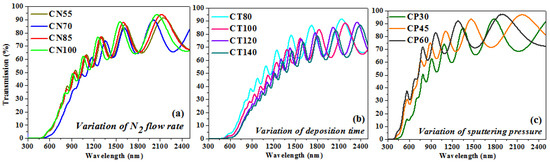
Figure 6.
Transmission graph of chromium oxynitride coatings developed at different (a) nitrogen gas flows, (b) sputtering times, and (c) deposition pressures.
Figure 6b indicates that as the deposition duration is extended from 80 to 140 min, the transmission of the developed coatings decreases. A potential explanation is that the increased thickness of the films formed at longer sputtering times (from 80 to 140 min) interferes with their transparency. In addition, surface roughness introduces sources of light scattering, and as the deposition time increases, the surface roughness also increases from 3.4 to 9.8 nm, so a greater quantity of light is anticipated to scatter while passing through the films, which may result in a decline in the transmission values. The estimated thickness from the transmission spectrum fringes appears to be in agreement with the surface profiler measurements.
Figure 6c shows that the transmission of chromium oxynitride films of varying sputtering pressures is greater than that of films produced with varying nitrogen gas flows and sputtering durations. In contrast with earlier scenarios, it exhibits increased transmission in the visible spectrum. The transmission spectra are shown to move towards the lower wavelength values as the deposition pressure is increased from 4.0 to 8.0 Pa. The transparency of the coatings developed at 4.0 Pa is lower, but it increases with the sputtering pressure, giving higher transmission at 8.0 Pa. A possible reason may be that the films are thinner as compared to the previous cases, and the surface roughness is also lower than them. Therefore, most of the light is able to be transmitted through the films, and consequently, the deposited films are more transparent than in the previous cases. The thickness of the coatings estimated from the transmission spectra and surface profilometer have a negligible difference between them.
The method proposed by J. C. Manifacier et al. [50] was used for determining the refractive index. Chromium oxynitride film packing density was determined using a formula detailed in greater depth elsewhere [51,52]. Figure 7a–c depicts the change in the film packing density and the refractive index as a function of nitrogen gas flow, deposition duration, and pressure. The refractive index and packing density of the film are lower when nitrogen is flowing at a rate of 55 sccm, but, as shown in Figure 7a, these properties rise when the nitrogen flow rate rises to 70 sccm. Both the refractive index and the packing density are almost identical for nitrogen flow rates of 85 and 100 sccm. Figure 7b shows that when the deposition time is extended, the film’s packing density and refractive index both rise. The films become dense and thicker with the rise in sputtering time, giving higher packing density and consequently an increase in refractive index values. When the deposition pressure is increased from 4.0 to 8.0 Pa, the refractive index drops (Figure 7c). As the deposition pressure is elevated, the packing density of the coating similarly drops. Compared to films formed with variable amounts of nitrogen and over longer periods of time, they have a lower packing density. One probable explanation is that the deposited layers are thinner than those in the two preceding situations.
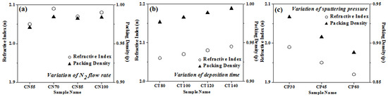
Figure 7.
Packing density and refractive index of chromium oxynitride coatings developed at different (a) nitrogen gas flows, (b) sputtering times, and (c) deposition pressures.
Using the Tauc relation, the band gap of the synthesized chromium oxynitride coatings was determined [53]. The band gap values for the chromium oxynitride coatings were calculated from Figure 8a–c over a range of nitrogen gas flows, sputtering times, and deposition pressures, and the corresponding values are summarized in Table 1. For the chromium oxynitride films, R. Mientus et al. [54] found that increasing the oxygen gas flow, or the oxygen content, resulted in wider band gap values. At a nitrogen gas flow of 55 sccm, the band gap is initially rather large. As the flow of nitrogen is elevated, the band gap values decrease in proportion to the value measured at 55 sccm. As can be seen in Figure 8a, the band gap value is at its lowest when the flow of nitrogen is 70 sccm. This could be because the nitrogen concentration is greater in this example than in the other three, resulting in a higher N/Cr ratio. Therefore, a reduction in band gap values was observed for the produced chromium oxynitride coatings with an increase in nitrogen gas flow, as opposed to an increase in band gap values with an increase in oxygen gas flow.
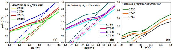
Figure 8.
Band gap of chromium oxynitride coatings developed at different (a) nitrogen gas flows, (b) sputtering times, and (c) deposition pressures.
According to the literature [55], Cr2N is a poor electron conductor in comparison to pure Cr, and its electron density (expressed as plasma energy) fluctuates with the nitrogen content. Figure 8b shows that when the deposition time of chromium oxynitride films escalates, the optical band gap reduces. As indicated in the XRD graphs (Figure 1b), the formation of a well crystalline Cr2N phase is observed with the rise in the sputtering duration. As the deposition period is prolonged, the nitrogen concentration rises, resulting in more dense coatings. These may have contributed to a decrease in the measured transmission spectra by increasing absorption in the visible range of the formed coatings. Therefore, shifting of the band gap values to those corresponding to chromium nitride is expected, and as a result, the decline in the optical band gap values with an increase in the deposition time was observed.
Initially at a deposition pressure of 4.0 Pa, lower band gap values were observed (Figure 8c). The probable explanation may be that there is the presence of Cr2N phases and nitrogen atoms, as seen in the XRD graphs and EDS data, respectively, at 4.0 Pa sputtering pressure. Due to a decrease in mean free path, an increase in sputtering pressure (from 6.0 to 8.0 Pa) causes a decrease in the deposition rate. This will reduce the number of reactive gas atoms in the chamber, as the majority will lose energy upon collision. Moreover, the reactivity of oxygen is great than nitrogen [56]; under such circumstances, the formation of the Cr2O3 phase is expected. Therefore, the Cr2O3 phase is only observed in the XRD graphs for nanocrystalline chromium oxynitride films deposited at 6.0 to 8.0 Pa sputtering pressures. The films are also more transparent, which is indicated by a corresponding increase in the transmission which is observed in the recorded spectra (Figure 6c). Hence, higher band gap values shifting towards the band gap of chromium oxide is expected with the rise in sputtering pressure.
4. Conclusions
When the flow of nitrogen gas is 70 sccm, nanocrystalline chromium oxynitride films exhibit structural change. The films deposited under this condition reveal the presence of the (1 1 0) texture of Cr2N and the (1 0 1 0) texture of the Cr2O3 phase, which is not observed for the films developed at 55, 85, and 100 sccm nitrogen gas flows. The resulting chromium oxynitride coatings are polycrystalline, with the distinct textures of the Cr2O3 and Cr2N phases evolving as the deposition times prolong. When the deposition pressure is increased to 6.0 to 8.0 Pa, only the (1 0 4) and (1 1 6) textures of the Cr2O3 phase are observed. Films formed at a nitrogen flow rate of 70 sccm exhibit the largest residual stresses, which are compressive in nature. With the increased deposition time, the chromium oxynitride films exhibit higher levels of residual stress and strain. When comparing films deposited with varying amounts of nitrogen and for varying amounts of time, tensile residual stresses are detected for chromium oxynitride. The stress and strain of the developed coatings increase with the increase in the sputtering pressure. The developed chromium oxynitride coatings are hydrophobic and water repellent, and the contact angle changes depending on the sputtering parameters. When the gas flow of nitrogen is increased from 55 to 70 sccm, the contact angle reaches a maximum of 102° and then decreases as the gas flow of nitrogen is increased to 85 and 100 sccm. A maximum contact angle of 108.7° was achieved at a deposition duration of 140 min, and both the surface roughness and contact angle increased linearly with the deposition time, whereas the surface energies of the formed films decreased. Surface roughness and contact angle values are rather insensitive to sputtering pressure, with a maximum contact angle of 97.4° being observed at a pressure of 6.0 Pa. The developed chromium oxynitride coatings exhibit partial transparency in the visible spectrum and full transparency in the NIR. When the volume flow of nitrogen being introduced into the system is increased from 55 to 70 sccm, the optical band gap is shown to decline from 1.87 to 1.69 eV. Increasing the deposition period from 80 to 140 min causes the band gap to drop from 1.75 to 1.65 eV, while increasing the sputtering pressure from 4.0 to 8.0 Pa increases the band gap from 1.92 to 2.09 eV. These hydrophobic, semi-transparent chromium oxynitride coatings may find use as protective coatings that are resistant to water, abrasion, and corrosion.
Author Contributions
S.R.: conceptualization, methodology, software, validation, and supervision. K.V.C.: formal analysis, investigation, data curation, and writing—original draft preparation. N.P.P.: resources and writing—review and editing. All authors have read and agreed to the published version of the manuscript.
Funding
This research received no external funding.
Institutional Review Board Statement
Not applicable.
Informed Consent Statement
Not applicable.
Data Availability Statement
Not applicable.
Conflicts of Interest
The authors declare no conflict of interest.
References
- Grudinin, V.A.; Sidelev, D.V.; Bleykher, G.A.; Yuriev, Y.N.; Krivobokov, V.P.; Berlin, E.V.; Grigoriev, V.Y.; Obrosov, A.; Weiß, S. Hot Target Magnetron Sputtering Enhanced by RF-ICP Source for CrNx Coatings Deposition. Vacuum 2021, 191, 110400. [Google Scholar] [CrossRef]
- Gui, B.; Zhou, H.; Liu, X.; Zhang, K.; Hu, H.; Yang, L.; Zhang, Y. Influence of N2 Flow Rate on Microstructure and Properties of CrNx Ceramic Films Prepared by MPP Technique at Low Temperature. Ceram. Int. 2021, 47, 20875–20884. [Google Scholar] [CrossRef]
- Zhang, M.; Shi, X.; Li, Z.; Xu, H. Enhanced Corrosion and Wear Resistance of Gradient Graphene-CrC Nanocomposite Coating on Stainless Steel. Carbon N. Y. 2021, 174, 693–709. [Google Scholar] [CrossRef]
- Su, Y.L.; Liu, T.H.; Su, C.T.; Cho, T.P. Effect of Chromium Content on the Dry Machining Performance of Magnetron Sputtered CrxC Coatings. Mater. Sci. Eng. A 2004, 364, 188–197. [Google Scholar] [CrossRef]
- Warcholinski, B.; Gilewicz, A.; Kuprin, A.S.; Tolmachova, G.N.; Ovcharenko, V.D.; Kuznetsova, T.A.; Zubar, T.I.; Khudoley, A.L.; Chizhik, S.A. Mechanical Properties of Cr-O-N Coatings Deposited by Cathodic Arc Evaporation. Vacuum 2018, 156, 97–107. [Google Scholar] [CrossRef]
- Fuentes, G.G.; Pérez-Gandarilla, L.; Medrano, A.; Fernández Palacio, J.; Bueno, R.; Arias-Egido, E.; Fernández, J. Microstructure and Indentation Hardness Study of CAE-PVD (Cr,Ti,Al)N Solid Solution Coatings Deposited Using a Combinatorial Multitarget Approach. Surf. Coat. Technol. 2021, 420, 127326. [Google Scholar] [CrossRef]
- Xu, X.; Sun, J.; Xu, Z.; Li, Z.; Su, F. Microstructure, Electrochemical and Tribocorrosion Behaviors of CrCN Nanocomposite Coating with Various Carbon Content. Surf. Coat. Technol. 2021, 411, 126997. [Google Scholar] [CrossRef]
- Li, Y.; Gao, L. Preparation and Characterization of the Nanocrystalline Ti0.5Cr0.5OxNy Powder. Mater. Lett. 2003, 57, 1062–1065. [Google Scholar] [CrossRef]
- Castaldi, L.; Kurapov, D.; Reiter, A.; Shklover, V.; Schwaller, P.; Patscheider, J. Effect of the Oxygen Content on the Structure, Morphology and Oxidation Resistance of Cr-O-N Coatings. Surf. Coat. Technol. 2008, 203, 545–549. [Google Scholar] [CrossRef]
- Li, W.Z.; Yi, D.Q.; Li, Y.Q.; Liu, H.Q.; Sun, C. Effects of the Constitution of CrON Diffusion Barrier on the Oxidation Resistance and Interfacial Fracture of Duplex Coating System. J. Alloys Compd. 2012, 518, 86–95. [Google Scholar] [CrossRef]
- Du, J.W.; Chen, L.; Chen, J.; Hu, C. Influence of Oxygen Addition on the Structure, Mechanical and Thermal Properties of CrN Coating. Surf. Coat. Technol. 2021, 411, 126992. [Google Scholar] [CrossRef]
- Wierzchoń, T.; Ulbin-Pokorska, I.; Sikorski, K. Corrosion Resistance of Chromium Nitride and Oxynitride Layers Produced under Glow Discharge Conditions. Surf. Coat. Technol. 2000, 130, 274–279. [Google Scholar] [CrossRef]
- Nunes, C.; Teixeira, V.; Prates, M.L.; Barradas, N.P.; Sequeira, A.D. Graded Selective Coatings Based on Chromium and Titanium Oxynitride. Thin Solid Films 2003, 442, 173–178. [Google Scholar] [CrossRef]
- Ho, W.Y.; Hsu, C.H.; Huang, D.H.; Lin, Y.C.; Chang, C.L.; Wang, D.Y. Corrosion Behaviors of Cr(N,O)/CrN Double-Layered Coatings by Cathodic Arc Deposition. Surf. Coat. Technol. 2005, 200, 1303–1309. [Google Scholar] [CrossRef]
- Urgen, M.; Ezirmik, V.; Senel, E.; Kahraman, Z.; Kazmanli, K. The Effect of Oxygen Content on the Temperature Dependent Tribological Behavior of Cr-O-N Coatings. Surf. Coat. Technol. 2009, 203, 2272–2277. [Google Scholar] [CrossRef]
- Guo, L.; Li, Z.; Wu, X.; Wang, K.; Abbas, F.; Wu, Y.; Zhang, F. Photocured Zwitterionic Coatings Containing POSS for Antifogging Applications. Coatings 2023, 13, 1152. [Google Scholar] [CrossRef]
- Yang, K.; Shi, J.; Wang, L.; Chen, Y.; Liang, C.; Yang, L.; Wang, L.N. Bacterial Anti-Adhesion Surface Design: Surface Patterning, Roughness and Wettability: A Review. J. Mater. Sci. Technol. 2022, 99, 82–100. [Google Scholar] [CrossRef]
- Patel, N.P.; Chauhan, K.V. Effect of Sputtering Power and Substrate Temperature on Structural, Optical, Wettability and Anti-Icing Characteristics of Aluminium Doped Zinc Oxide. Mater. Res. Express 2022, 9, 076402. [Google Scholar] [CrossRef]
- Liu, Y.; Wu, M.; Guo, C.; Zhou, D.; Wu, Y.; Wu, Z.; Lu, H.; Zhang, H.; Zhang, Z. A Review on Preparation of Superhydrophobic and Superoleophobic Surface by Laser Micromachining and Its Hybrid Methods. Crystals 2023, 13, 20. [Google Scholar] [CrossRef]
- Ji, X.; Li, H.; Qin, Y.; Yan, J. Performance Enhancement of Self-Cleaning Cotton Fabric with ZnO NPs and Dicarboxylic Acids. Crystals 2022, 12, 214. [Google Scholar] [CrossRef]
- Shi, Y.; Long, S.; Fang, L.; Yang, S.; Pan, F. Effect of Nitrogen Content on the Properties of CrNxOyCz Coating Prepared by DC Reactive Magnetron Sputtering. Appl. Surf. Sci. 2008, 254, 5861–5867. [Google Scholar] [CrossRef]
- Rawal, S.K.; Chawla, A.K.; Jayaganthan, R.; Chandra, R. Optical and Hydrophobic Properties of Co-Sputtered Chromium and Titanium Oxynitride Films. Appl. Surf. Sci. 2011, 257, 8755–8761. [Google Scholar] [CrossRef]
- Patel, K.D.; Amin, M.H.; Patel, N.A.; Patel, D.Y.; Chauhan, K.V. Study the Effect of Sputtering Power on Wettability Properties of Chromium Oxide Coated GFRP Composite Materials. Mater. Today Proc. 2021, 47, 5881–5885. [Google Scholar] [CrossRef]
- Ehrlich, A.; Kühn, M.; Richter, F.; Hoyer, W. Complex Characterisation of Vacuum Arc-Deposited Chromium Nitride Thin Films. Surf. Coat. Technol. 1995, 76–77, 280–286. [Google Scholar] [CrossRef]
- Tabbal, M.; Kahwaji, S.; Christidis, T.C.; Nsouli, B.; Zahraman, K. Pulsed Laser Deposition of Nanostructured Dichromium Trioxide Thin Films. Thin Solid Films 2006, 515, 1976–1984. [Google Scholar] [CrossRef]
- Adamczyk, A. The Influence of Different Types of SiO2 Precursors and Ag Addition on the Structure of Selected Titania-Silica Gels. Crystals 2023, 13, 811. [Google Scholar] [CrossRef]
- Yuan, Y.; Zhang, B.; Sun, J.; Jonnard, P.; Le Guen, K.; Tu, Y.; Yan, C.; Lan, R. Structure and Optical Properties of CrOxNy Films with Composition Modulation. Surf. Eng. 2020, 36, 411–417. [Google Scholar] [CrossRef]
- Huang, J.H.; Lau, K.W.; Yu, G.P. Effect of Nitrogen Flow Rate on Structure and Properties of Nanocrystalline TiN Thin Films Produced by Unbalanced Magnetron Sputtering. Surf. Coat. Technol. 2005, 191, 17–24. [Google Scholar] [CrossRef]
- Chawla, V.; Jayaganthan, R.; Chandra, R. Structural Characterizations of Magnetron Sputtered Nanocrystalline TiN Thin Films. Mater. Charact. 2008, 59, 1015–1020. [Google Scholar] [CrossRef]
- Welzel, U.; Ligot, J.; Lamparter, P.; Vermeulen, A.C.; Mittemeijer, E.J. Stress Analysis of Polycrystalline Thin Films and Surface Regions by X-ray Diffraction. J. Appl. Crystallogr. 2005, 38, 1–29. [Google Scholar] [CrossRef]
- Janssen, G.C.A.M. Stress and Strain in Polycrystalline Thin Films. Thin Solid Films 2007, 515, 6654–6664. [Google Scholar] [CrossRef]
- Pelleg, J.; Zevin, L.Z.; Lungo, S.; Croitoru, N. Reactive-Sputter-Deposited TiN Films on Glass Substrates. Thin Solid Films 1991, 197, 117–128. [Google Scholar] [CrossRef]
- Greene, J.E.; Sundgren, J.E.; Hultman, L.; Petrov, I.; Bergstrom, D.B. Development of Preferred Orientation in Polycrystalline TiN Layers Grown by Ultrahigh Vacuum Reactive Magnetron Sputtering. Appl. Phys. Lett. 1995, 67, 2928. [Google Scholar] [CrossRef]
- Petrov, I.; Barna, P.B.; Hultman, L.; Greene, J.E. Microstructural Evolution during Film Growth. J. Vac. Sci. Technol. A Vac. Surf. Film. 2003, 21, S117–S128. [Google Scholar] [CrossRef]
- Chawla, A.K.; Singhal, S.; Gupta, H.O.; Chandra, R. Effect of Sputtering Gas on Structural and Optical Properties of Nanocrystalline Tungsten Oxide Films. Thin Solid Films 2008, 517, 1042–1046. [Google Scholar] [CrossRef]
- Knotek, O.; Elsing, R.; Krämer, G.; Jungblut, F. On the Origin of Compressive Stress in PVD Coatings—An Explicative Model. Surf. Coat. Technol. 1991, 46, 265–274. [Google Scholar] [CrossRef]
- Thornton, J.A.; Tabock, J.; Hoffman, D.W. Internal Stresses in Metallic Films Deposited by Cylindrical Magnetron Sputtering. Thin Solid Films 1979, 64, 111–119. [Google Scholar] [CrossRef]
- Zhou, M.; Nose, M.; Nogi, K. Influence of Nitrogen on the Structure and Mechanical Properties of r.f.-Sputtered Cr-B-N Thin Films. Surf. Coat. Technol. 2004, 183, 45–50. [Google Scholar] [CrossRef]
- Venkataraj, S.; Severin, D.; Mohamed, S.H.; Ngaruiya, J.; Kappertz, O.; Wuttig, M. Towards Understanding the Superior Properties of Transition Metal Oxynitrides Prepared by Reactive DC Magnetron Sputtering. Thin Solid Films 2006, 502, 228–234. [Google Scholar] [CrossRef]
- D’Heurle, F.M.; Harper, J.M.E. Note on the Origin of Intrinsic Stresses in Films Deposited via Evaporation and Sputtering. Thin Solid Films 1989, 171, 81–92. [Google Scholar] [CrossRef]
- Amor, S.B.; Rogier, B.; Baud, G.; Jacquet, M.; Nardin, M. Characterization of Zirconia Films Deposited by r.f. Magnetron Sputtering. Mater. Sci. Eng. B 1998, 57, 28–39. [Google Scholar] [CrossRef]
- Berasategui, E.G.; Zubizarreta, C.; Bayón, R.; Barriga, J.; Barros, R.; Martins, R.; Fortunato, E. Study of the Optical, Electrical and Corrosion Resistance Properties of AZO Layers Deposited by DC Pulsed Magnetron Sputtering. Surf. Coat. Technol. 2015, 271, 141–147. [Google Scholar] [CrossRef]
- Han, S.I.; Kim, H.B. A Study on Properties of RF-Sputtered Al-Doped ZnO Thin Films Prepared with Different Ar Gas Flow Rates. Appl. Sci. Converg. Technol. 2016, 25, 145–148. [Google Scholar] [CrossRef][Green Version]
- Patel, N.P.; Chauhan, K.V. Effects of Argon Partial Pressure Variations on Wettability and Anti-Icing Characteristics of Aluminum Doped ZnO Thin Films. Mater. Res. 2023, 26, e20220339. [Google Scholar] [CrossRef]
- Mohammadtaheri, M.; Yang, Q.; Li, Y.; Corona-Gomez, J. The Effect of Deposition Parameters on the Structure and Mechanical Properties of Chromium Oxide Coatings Deposited by Reactive Magnetron Sputtering. Coatings 2018, 8, 111. [Google Scholar] [CrossRef]
- Rawal, S.K.; Kumar, A.; Chawla, V.; Jayaganthan, R.; Chandra, R. Structural, Optical and Hydrophobic Properties of Sputter Deposited Zirconium Oxynitride Films. Mater. Sci. Eng. B 2010, 172, 259–266. [Google Scholar] [CrossRef]
- Xiu, Y.; Xiao, F.; Hess, D.W.; Wong, C.P. Superhydrophobic Optically Transparent Silica Films Formed with a Eutectic Liquid. Thin Solid Films 2009, 517, 1610–1615. [Google Scholar] [CrossRef]
- Patel, N.P.; Chauhan, K.V.; Desai, M.K. Effects of Power and Temperature on the Structural, Anti-Icing, Wettability, and Optical Properties of Zinc Oxide Thin Films. Ceram. Int. 2023, 49, 26943–26949. [Google Scholar] [CrossRef]
- Nosonovsky, M.; Bhushan, B. Multiscale Dissipative Mechanisms and Hierarchical Surfaces; Springer: Berlin/Heidelberg, Germany, 2008; ISBN 978-3-540-78425-8. [Google Scholar]
- Manifacier, J.C.; Gasiot, J.; Fillard, J.P. A Simple Apparatus for the Determination of the Optical Constants and the Thickness of Absorbing Thin Films. J. Phys. E 1976, 9, 1002–1004. [Google Scholar] [CrossRef]
- Harris, M.; Macleod, H.A.; Ogura, S.; Pelletier, E.; Vidal, B. The Relationship between Optical Inhomogeneity and Film Structure. Thin Solid Films 1979, 57, 173–178. [Google Scholar] [CrossRef]
- Xiao, Q.L.; Xu, C.; Shao, S.Y.; Da Shao, J.; Fan, Z.X. Y2O3 Stabilized ZrO2 Thin Films Deposited by Electron-Beam Evaporation: Optical Properties, Structure and Residual Stresses. Vacuum 2008, 83, 366–371. [Google Scholar] [CrossRef]
- Alsaad, A.; Al Dairy, A.R.; Ahmad, A.; Qattan, I.A.; Al Fawares, S.; Al-Bataineh, Q. Synthesis and Characterization of Polymeric (PMMA-PVA) Hybrid Thin Films Doped with TiO2 Nanoparticles Using Dip-Coating Technique. Crystals 2021, 11, 99. [Google Scholar] [CrossRef]
- Mientus, R.; Grötschel, R.; Ellmer, K. Optical and Electronic Properties of CrOxNy Films, Deposited by Reactive DC Magnetron Sputtering in Ar/N2/O2(N2O) Atmospheres. Surf. Coat. Technol. 2005, 200, 341–345. [Google Scholar] [CrossRef]
- Logothetidis, S.; Patsalas, P.; Sarakinos, K.; Charitidis, C.; Metaxa, C. The Effect of Crystal Structure and Morphology on the Optical Properties of Chromium Nitride Thin Films. Surf. Coat. Technol. 2004, 180–181, 637–641. [Google Scholar] [CrossRef]
- Martin, N.; Banakh, O.; Santo, A.M.E.; Springer, S.; Sanjinés, R.; Takadoum, J.; Lévy, F. Correlation between Processing and Properties of TiOxNy Thin Films Sputter Deposited by the Reactive Gas Pulsing Technique. Appl. Surf. Sci. 2001, 185, 123–133. [Google Scholar] [CrossRef]


Disclaimer/Publisher’s Note: The statements, opinions and data contained in all publications are solely those of the individual author(s) and contributor(s) and not of MDPI and/or the editor(s). MDPI and/or the editor(s) disclaim responsibility for any injury to people or property resulting from any ideas, methods, instructions or products referred to in the content. |
© 2023 by the authors. Licensee MDPI, Basel, Switzerland. This article is an open access article distributed under the terms and conditions of the Creative Commons Attribution (CC BY) license (https://creativecommons.org/licenses/by/4.0/).