1. Introduction
Sensor technology, communication technology, and computer technology can realize information extraction, transmission, and processing, which are the three pillars of modern information technology. With the progress of science and technology, modern measurement and control technologies have a deeper and wider impact on modern information society. Accelerometers, as the preferred vibration measurement sensors, have been widely used in vibration and shock testing, signal analysis, vibration calibration, and mechanical dynamic experiments in the fields of ships, bridges, aviation, weaponry, construction, etc., especially in the aerospace field, where they have very important applications [
1,
2].
An accelerometer is a device used to measure acceleration by sensing static continuous force or dynamic vibration and motion, and its acceleration types are vibration, shock, motion, and earthquake. According to the different sensitive elements, accelerometers can be divided into piezoresistive, capacitive, piezoelectric, and resonant. The principle of a capacitive accelerometer is to convert the change in acceleration into the change in capacitance and then calculate acceleration through the amount of capacitance change in order to complete the measurement of the vibration acceleration of the system [
3,
4,
5]. When the system is stationary, the measured resistance of the pressure-sensitive material of the resistive accelerometer is the calibration resistance. System vibration, the pressure-sensitive material with the cantilever beam displacement and deformation, and the measured resistance change, thus completing the acceleration to the resistance of the physical quantity conversion. The pressure-sensitive material is generally a semiconductor material, with the attachment to the cantilever beam in different positions. Even with the same vibration acceleration, there will be a different amount of resistance change in the pressure-sensitive material [
6,
7,
8]. When the acceleration from the sensitive axis direction input is applied, the accelerometer in the mass of the block will experience an inertial force under the action of the displacement. This displacement in the form of force through the transmission mechanism to act on the resonator is caused by the resonator’s intrinsic frequency change. With the help of the frequency measurement circuit to pick up the amount of resonator frequency change, and then through the formula of frequency and acceleration, the input acceleration can be obtained [
9,
10,
11].
Compared with other types of sensors, piezoelectric accelerometers have the advantages of a large range, a wide-frequency band, a simple structure, stable performance, good output linearity, etc. The principle of a piezoelectric accelerometer is based on the property of the active element, and its structure is mainly composed of a mass block, a piezoelectric sensitive element, and a base. When a specific acceleration is given to an object, the accelerometer will be subjected to the same. Through the action of the mass block, the piezoelectric element will be deformed due to the inertial force in the opposite direction of the acceleration of the device to be measured. Due to the piezoelectric effect, the two surfaces of the piezoelectric element will accumulate equal amounts of opposite charges, thus producing a potential difference [
12]. When the measured vibration frequency is much lower than the intrinsic frequency of the accelerometer, the change in force is proportional to the measured acceleration. Therefore, the acceleration of the object to be measured can be calculated by collecting the charge signal from the sensor. Take the compression mode accelerometer as an example; its working principle is shown in
Figure 1.
There are many companies that manufacture accelerometers, such as Brüel & Kjær, Gulton Manufacturing, Kistler, PCB, Endevco and others. Structurally, it has gone through changes and advancements from compression type to shear type (planar shear, triangular shear, annular shear, and orthogonal shear). In terms of electrical performance, piezoelectric accelerometer technology has progressed from a high-impedance charge output type (PE) to a low-impedance voltage output type (IEPE). Currently, most piezoelectric accelerometers have built-in charge-voltage converter circuits and operate with low-impedance voltage output. Their conventional low-frequency response is typically 0.5 Hz, making them suitable for most shock and vibration measurement applications. Despite the mature development of piezoelectric acceleration sensors, innovation in the means of piezoelectric accelerometer design has become a pressing issue as the application areas continue to expand.
This review aims to present an overview of various modes of piezoelectric accelerometers and piezoelectric materials and provide researchers with a guide to gain a better understanding of research in the field of piezoelectric accelerometers. Lastly, a brief summary and anticipated future development in the area of piezoelectric accelerometers.
2. The Technical Indicators of Piezoelectric Accelerometer
- (1)
Sensitivity
Sensitivity is the ratio of the output charge of a piezoelectric accelerometer to the vibration (shock) acceleration to which the device is subjected. The equivalent circuit of the piezoelectric accelerometer is shown in
Figure 2. A piezoelectric accelerometer can be equated to a circuit with an ideal charge source
Qa connected in parallel with
Ca and a cable distribution capacitance
Cc. Or a circuit consisting of an ideal voltage source in series with a capacitor with cable distribution capacitance
Cc as a load. The sensitivity of a piezoelectric accelerometer can be expressed in terms of either charge sensitivity or voltage sensitivity by dividing the input acceleration
as by the output charge
Qa or the output voltage
Va, respectively [
13]:
Voltage sensitivity:
Charge sensitivity:
Output voltage:
- (2)
The inherent frequency
The simplified mechanical model of the piezoelectric accelerometer is shown in
Figure 3, where
m is the mass block,
k is the spring stiffness, denotes the piezoelectric coefficient of the piezoelectric ceramic, and
c is the damping coefficient.
The mechanical expression for the motion of the mass block:
where
x is the vibrational displacement of the mass block, and
y is the displacement response of vibrating surfaces.
After performing the transformation,
A(w) and
φ(w) of the accelerometer can be obtained as follows:
where
is the damping ratio of the inertial system,
is the intrinsic frequency of the system,
z is the displacement of the mass block with respect to the base, and
yw
2 is the measured acceleration value.
The inherent frequency is the frequency that is affected only by the inherent properties of the object (mass, material, structure, elasticity, etc.). In order to avoid resonance and signal distortion when performing acceleration measurements, the accelerometer has a certain operating frequency range, which is related to the inherent frequency of the device, and generally, the system operating frequency is 1/5 to 1/3 of the inherent frequency, between which the signal can be obtained without distortion.
Figure 4 shows the available frequency range of a standard piezoelectric accelerometer [
13].
- (3)
Inherent capacitance
The piezoelectric accelerometer generates an electrical charge when subjected to an external force along its sensitive axis, so it is equivalent to a charge source. When the electrode surface of the piezoelectric element gathers charge, it is equivalent to a capacitor. According to the relationship Q = VC, it can be concluded that the lower the inherent capacitance of the sensor, the higher its output voltage and the less noise it generates.
- (4)
Operating temperature range
Piezoelectric accelerometers are capable of vibration measurements over a wide temperature range. However, due to the properties of the piezoelectric material, the voltage and charge sensitivity, as well as the impedance, will change when the accelerometer is operated at a non-reference temperature.
- (5)
Lateral sensitivity
Lateral sensitivity is the sensitivity of the accelerometer when subjected to acceleration perpendicular to the direction of the main axis. The lateral sensitivity is generally expressed as a percentage of the main axis sensitivity. The smaller the lateral sensitivity, the smaller the accelerometer error. In order to reduce lateral sensitivity, the main axis of the sensor should be as symmetrical as possible [
14].
3. Structure of Piezoelectric Accelerometers
3.1. Compression Mode Piezoelectric Accelerometer
A compression mode accelerometer has a simple structure, strong rigidity, high output sensitivity, and other characteristics that make it suitable for dynamic measurement and widely used in vibration measurement. The structure of the center compression mode accelerometer is shown in
Figure 5a, which mainly consists of a mass block, a fixed nut, a piezoelectric element, and a base. In order to maintain the stability of the accelerometer, a central pillar is added at the central axis of the base to connect the mass block, the piezoelectric element, and the base together. The maximum intrinsic frequency can be obtained when the mass of the mass block is comparable to the mass of the base. The piezoelectric element–spring–mass system is fixed on a central cylinder connected to the accelerometer base using the thickness vibration mode [
13]. This structure is very stable and has high resonant frequencies. However, since the piezoelectric element is bolted to the base, any dynamic changes in the base, such as base strain or thermal expansion, can cause stress changes on the piezoelectric element and output the wrong signal. In order to reduce the effects of base strain and thermal instability on the object under test, the compression type can also be designed as an inverted center compression type or isolated base compression type structure. The isolated base compression type is designed with a mechanical isolation slot between the base and the piezoelectric element. A hollow inertial mass block is employed as a thermal barrier to effectively reduce the wrong output due to base strain and transient temperature, as shown in
Figure 5b [
2].
3.2. Shear-Mode Piezoelectric Accelerometer
The piezoelectric element of the center compression type accelerometer is in complete contact with the base, and the vibration or temperature change of the base will affect the piezoelectric effect of the piezoelectric element and make the sensor system generate errors. In shear accelerometers, the piezoelectric element is not in contact with the base, thus avoiding the influence of the base on the piezoelectric element. Compared to compression mode accelerometers, shear-mode accelerometers are more complex to machine and assemble, but their lateral sensitivity and environmental sensitivity are smaller than compression ones [
1]. The structure of a shear-mode accelerometer is shown in
Figure 6a. The shear-type structure sandwiches the piezoelectric element between the central column and the inertial mass block in a fixed manner, and the preload bolt provides the preload force required to form a rigid structure with resistance to transient temperature and base strain effects. Under acceleration, the mass block exerts a shear stress on the piezoelectric element. The sensitive axis direction is vertical, and the sensitivity is maximum in this direction. Ideally, the sensitivity in the orthogonal direction is zero. However, due to structural tolerances or the cross-sensitivity of the crystal itself, commercial sensors have sensitivity in the direction perpendicular to the sensitive axis, making them cross-sensitive (a few percent of the sensitive axis sensitivity). The lateral sensitivity of piezoelectric accelerometers is generally not allowed to exceed 5%, and the influencing factors include the design of the mechanical structure of the sensor, the processing accuracy of the parts, and the accuracy of the assembly process. In order to reduce the lateral sensitivity, the overall structure should be designed to ensure that the overall structure is symmetrical on the sensitive axis [
11].
In addition to the planar shear mode, there are triangular shear-mode structures (
Figure 6b) as well as annular shear-mode structures. The three mass-spring systems in the triangular shear-mode structure are tightened with a preload ring to form a complete spring–mass system. The triangular shear structure has the highest sensitivity-to-mass ratio and a relatively high resonant frequency compared to other structure types. The overall spring–mass system does not contain adhesives or bolts, which ensures the desired performance and reliability. A cylindrical center column and a circular piezoelectric element are used in the ring shear-mode structure. The curved mass block, which fits snugly into the piezoelectric element, is held in place with a preload ring, and this structure is often used to measure shock acceleration [
15].
3.3. Bending Accelerometer
The bending accelerometer structure is shown in
Figure 7. When the accelerometer senses the vibration, the piezoelectric element is bent and deformed under its own inertial force, and the charge signal is output. The bending structure is insensitive to lateral vibration and has excellent thermal stability, but its shock resistance is poor, and it is usually used as a low vibration magnitude accelerometer for structural analysis testing [
16,
17].
3.4. IEPE Accelerometer
In a conventional piezoelectric accelerometer, the charge generated by the piezoelectric element is transmitted through a cable to an amplifier, and the signal is acquired by a data acquisition card. The capacitive loading of the cable increases the noise and requires the use of expensive low-noise cables [
18]. Piezoelectric accelerometers with integral electronics (IEPE) integrate piezoelectric transducers and electronic circuitry in a shielded housing and are primarily used to measure response characteristics in the frequency range of 1 Hz to 19 kHz and even below. IEPE accelerometers have the advantages of a high signal-to-noise ratio, wide frequency response, low output impedance, high sensitivity, insensitivity to electromagnetic interference, and the ability to be implemented in miniature designs [
19].
The IEPE accelerometer structure is mainly composed of two parts: the piezoelectric sensor and the signal debugging circuit, and its working principle diagram is shown in
Figure 8. In dynamic acceleration measurements, the IEPE accelerometer operates in the frequency range below the resonant frequency of the PE sensor. In the normal operating frequency range, the PE sensor is essentially a capacitive signal source with high impedance. Charge amplifiers and voltage amplifiers are two basic types of internal electronic circuits in IEPE accelerometers, whose main function is to convert the charge signal generated by the PE sensor into a voltage output signal [
20,
21]. Typically, the amplifier circuit consists of an input stage based on a field effect transistor (FET) and an output stage based on a bipolar junction transistor (BJT). The amplifier converts the high-impedance charge signal generated by the PE sensor into a low-impedance voltage signal that can be transmitted over long distances. The low output impedance means that the output signal can be transmitted to the signal conditioning circuit using low-cost conventional coaxial or other types of shielded cable [
22,
23,
24,
25].
3.5. MEMS Type Piezoelectric Accelerometer
Micro-electro-mechanical systems (MEMS) are traditional semiconductor manufacturing and microfabrication technologies. MEMS accelerometers have many advantages compared with traditional accelerometers, such as small size, light weight, low energy consumption, and so on. They have received wide attention, and their principle schematic diagram is shown in
Figure 9 [
26]. MEMS accelerometers can be divided into piezoresistive, capacitive, piezoelectric, thermal conductivity, and other types according to the different detection methods. Among them, MEMS piezoelectric accelerometers have the following advantages over other types of accelerometers: A wide dynamic range, wide frequency range, and easy integration into existing measurement systems, which are widely used in engine vibration analysis, auditory devices, and other fields. At the same time, there are some shortcomings: no steady-state response, high output impedance, and high requirements for detection circuits [
27].
The piezoelectric MEMS accelerometer is formed by using the piezoelectric effect, and the structure consists of a mass block connected to a piezoelectric element and connected to the shell by an elastic structure. The working principle is that the mass block is displaced under the excitation of acceleration, which leads to the deformation of the piezoelectric film [
28]. The piezoelectric film generates an electric charge output due to the stress, which is amplified by the amplifier and collected by the computer control system to detect the acceleration of the object to be measured [
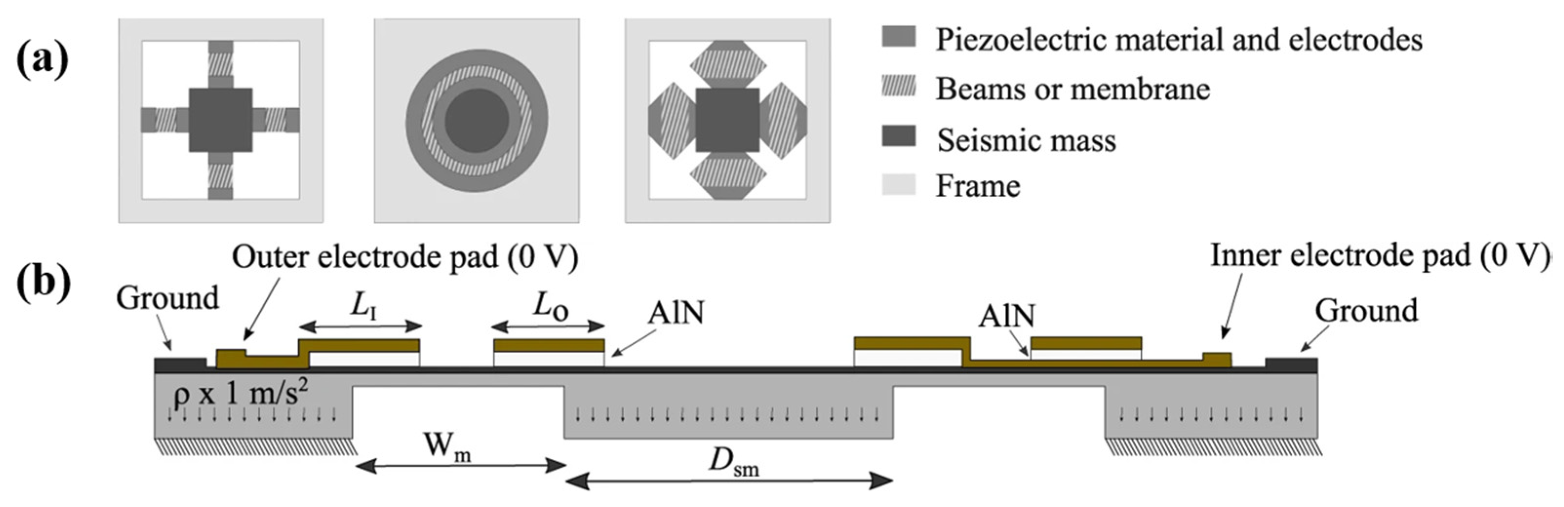
29]. There are three common structures of piezoelectric accelerometers (
Figure 10a): Four-armed beam type, ring type, and hexagonal structure type.
Figure 10b shows the section view of an aluminum nitride (AlN)-based MEMS piezoelectric accelerometer [
30].
The advantages and disadvantages of the different structure types of piezoelectric accelerometers are summarized in the
Table 1.
4. Commonly Used Piezoelectric Materials
4.1. Piezoelectric Ceramic Materials
4.1.1. PZT Piezoelectric Ceramic Materials
PZT (lead zirconate titanate) series piezoelectric ceramics are widely used piezoelectric materials today due to their excellent piezoelectric properties, dielectric properties, and stability [
31,
32]. PZT-5 and PZT-5H are well established commercially, and products such as PCB and Murata Manufacturing use PZT ceramics as piezoelectric elements in piezoelectric accelerometers. PZT-5H has a great piezoelectric constant, dielectric properties, and electromechanical coupling coefficient, which affords it high sensitivity and fast response. The piezoelectric constant of the piezoelectric effect of a shear-mode accelerometer is mainly
d15. Shi et al. used PZT-5H as the sensitive element to prepare a triangular shear-mode accelerometer with a sensitivity of 1600 pC/g, the
d15 of PZT-5H is 741 pC/N. With the modification of PZT, its piezoelectric performance has been greatly improved. The PNN-PZT piezoelectric ceramics prepared by Yang Yue et al. have excellent piezoelectric properties (
d33 = 887 pC/N), but the Curie temperature is low (
TC = 120 °C), which limits their applicability [
33,
34].
4.1.2. Lead-Free Piezoelectric Ceramics
In the field of piezoelectric ceramics, lead-based piezoelectric ceramics such as Pb(Zr,Ti)O
3 have been dominating. However, the content of Pb in lead-based piezoelectric ceramics accounts for more than 70% of the total raw materials, which can cause serious harm to the ecological environment and human beings. In recent years, some international decrees have been passed to restrict the use of lead-containing materials, so it is important to develop high-performance lead-free piezoelectric ceramics. At present, the main lead-free piezoelectric ceramic systems are barium titanate-based, bismuth ferrite-based, bismuth layered structure, tungsten bronze structure, potassium sodium niobate, and sodium bismuth titanate-based lead-free piezoelectric ceramics [
35,
36,
37].
BF-BT ((1-
x)BiFeO
3-
xBaTiO
3)-based lead-free piezoceramics are expected to be used in high-temperature piezoelectric accelerometers because of their high Curie temperature (~500 °C) and good piezoelectric properties (
d33~190 pC/N) [
38,
39,
40]. The effect of BT content in (1-
x)BiFeO
3-
xBaTiO
3-0.0035MnO
2-0.001Li
2CO
3 on microstructure, electrical properties, on the sensitivity of piezoelectric accelerometers was investigated by the group of Huabin Yang and Haibo Zhang [
41]. BF-0.30BT piezoelectric accelerometers achieved a sensitivity of ~40 pC/g and exhibited good stability below 400 °C (
Figure 11), indicating that the BF-BT-based lead-free piezoelectric ceramics have great potential for high-temperature accelerometer applications.
Lee et al. [
42] synthesized 0.76(Bi
0.5Na
0.5)TiO
3-0.04(Bi
0.5Li
0.5)TiO
3-0.2(Bi
0.5K
0.5)TiO
3 (0.76BNT-0.04BLT-0.2BKT) piezoelectric ceramics with
Td = 130 °C,
d33 = 206 pC/N. It was also used as a sensitive element to make a compression mode accelerometer. The sensitivity of the accelerometer was 107 pC/g at room temperature, which decreased sharply around the depolarization temperature
Td (110–130 °C). The accelerometer showed good stability from room temperature to 110 °C (
Figure 12). As a result, it is concluded that the temperature stability and thermal aging resistance of the
d33 are more important features for actual applications in the piezoelectric elements of a temperature-insensitive accelerometer.
Bismuth layer structured ferroelectrics (BLSFs) are piezoelectric ceramics whose chemical formula can be expressed by the general formula (Bi
2O
2)
2+ (A
m−1B
mO
3m+1)
2−, its crystalline structure is shown in
Figure 13. Due to the characteristics of high Curie temperature, low aging rate, high dielectric breakdown strength, high mechanical quality factor, and higher high-temperature resistivity than perovskite piezoelectric ceramics such as Pb(Zr,Ti)O
3, Bi
0.5Na
0.5TiO
3, etc. Therefore, BLSF piezoelectric ceramics are the most promising class of high-temperature piezoelectric ceramic materials, and they are also the preferred solution for high-temperature piezoelectric vibration sensors. Among them, bismuth titanate (Bi
4Ti
3O
12, BIT), as one of the earliest BLSFs, is the first choice for high-temperature piezoelectric vibration sensors because of its high Curie temperature (
TC = 675 °C) and good fatigue resistance [
43,
44].
Due to the specificity of its crystal structure, there are several main disadvantages: Its spontaneous polarization is mainly in the a-b plane direction, so the ceramic piezoelectric coefficient
d33 of random grain orientation is lower; due to the easy volatilization of bi elements in high-temperature environments, with the increase in temperature, the resistance decreases significantly, which is easy to conduct at the actual use temperature but cannot meet the application requirements; BIT can easily form lamellar grains, which in turn can easily form current channels after ceramic sintering and affect its polarization process [
45].
Among the high-temperature piezoelectric materials with tungsten bronze structures, the meta-niobate PbNb
2O
6 (PN) has received the most attention. The characteristics of bi-niobate materials are high Curie temperature,
TC = 570 °C, good thermal stability below Curie temperature; large anisotropy of each piezoelectric coefficient,
d33/
d31 > 10, low mechanical quality factor,
Qm = about 10. Therefore, such materials are suitable as high-temperature transducers. Unlike PZT materials, which are simple to prepare, meta-niobates have a high sintering temperature (1230 °C) and produce large volume changes during sintering due to phase changes, which affect the densities of the materials and are prone to cracking. The polarization of meta-niobate is difficult, and the dielectric constant is low [
46].
4.2. Piezoelectric Single Crystal Materials
Relaxor ferroelectrics are a type of ferroelectric material, and relaxor ferroelectric single crystals such as Pb(Mg
1/3Nb
2/3)O
3-PbTiO
3 (PMN-PT) and Pb(Zn
1/3Nb
2/3)O
3-PbTiO
3 (PZN-PT) have attracted attention due to their ultra-high piezoelectric properties. The ultra-high piezoelectric strain coefficient (
d33 > 2000 pC/N,
d31~−1035 pC/N) and electromechanical coupling factor
k33 (>0.9) of relaxor PT single crystals far exceed those of the commonly used polycrystalline ceramic Pb(ZrTi)O
3 (PZT), making them promising for electromechanical applications. Due to the high piezoelectric properties and low dielectric loss of PT relaxor single crystals, they are very suitable for low-noise, high-sensitivity accelerometers [
47,
48,
49]. However, relaxor ferroelectric single crystals, which have a relatively low transition temperature, coercive field, and mechanical quality factor, have not been applied.
In addition, yttrium calcium borate (YCOB), lanthanum gallium silicate (LGS), tantalum calcium gallium silicate (CTGS), and lithium niobate are widely used as piezoelectric element materials for high-temperature piezoelectric accelerometers due to their excellent piezoelectric properties, high electromechanical coupling coefficient, and good high-temperature stability. These single crystals were reported to be free of phase transition up to their respective melting points (1450–1510 °C) and to have high resistivity and low dielectric loss at elevated temperatures [
50,
51].
Rare earth calcium oxyborate single crystals ReCa
4O(BO
3)
3 (ReCOB crystal, Re = La, Y, Gd, Ga) is a single crystal invented in the 1990s with good high-temperature piezoelectric properties as well as stable chemical properties. ReCOB crystal has high-temperature resistivity and can work stably at temperatures as high as 1000 °C, so it is widely used in the field of high-temperature piezoelectric sensors. However, ReCOB crystals are fragile during vibration. The crystal cut type has a large impact on the piezoelectric properties, so it is important to choose the optimal crystal cut (
Figure 14) [
52,
53,
54].
Shujun Zhang et al. [
52] fabricated a compressive piezoelectric accelerometer for ultra-high temperature YCOB single crystals (
d33~6.5 pC/N), whose structure is schematically shown in
Figure 15a. The accelerometer was operated at temperatures up to 1000 °C with a frequency range of 100–600 Hz. The sensitivity was 2.4 ± 0.4 pC/g at the measured temperature and frequency ranges. It was shown that it is feasible to use YCOB single crystals as components of high-temperature piezoelectric sensors.
Kim et al. [
53] prepared a shear piezoelectric accelerometer without thin-film electrodes using YCOB crystals as piezoelectric elements, as shown in
Figure 16a. The piezoelectric strain coefficient
d26 of YCOB prepared by the authors is around 10 pC/N (crystal cut: YXt −30°). This sensor did not use platinum electrodes to avoid the degradation of thin-film electrodes at high temperatures. The room temperature sensitivity of this accelerometer is 5.9 ± 0.06 pC/g, and its average sensitivity is 6.0 ± 0.12 pC/g during 9 h of holding at 1000 °C, with good thermal stability, which demonstrates the feasibility of YCOB as a sensitive element for high-temperature piezoelectric accelerometers.
Lanthanum gallium silicate crystal (La
3Ga
5SiO
14) is also a kind of piezoelectric single crystal widely used in high-temperature piezoelectric sensors. It belongs to the tripartite crystal system and can work stably at 900 °C. Its shear piezoelectric constant
d26~−5.66 pC/N. The crystal has been used in a large number of applications, such as high-temperature piezoelectric sensors and intermediate-frequency filters [
54,
55].
Gallium tantalum calcium silicate crystal (Ca
3TaGa
3Si
2O
14), abbreviated as CTGS crystal, is a high-temperature piezoelectric crystal with excellent piezoelectric properties, a high electromechanical coupling coefficient, high-performance consistency, and no phase change from room temperature to melting point (1350 °C). The piezoelectric accelerometers made with CTGS crystals can work stably at 900 °C [
56].
A broad range of ferroelectric materials and non-ferroelectric piezoelectric single crystals for sensors have been surveyed.
Figure 17 summarizes the
deff versus maximum usage temperature range for various piezoelectric materials. Ferroelectric single crystals and ferroelectric ceramics have high piezoelectric properties, but the Curie temperature is lower, and piezoelectric single crystals have a larger temperature range and are more suitable for high-temperature sensors [
50,
51,
54,
55,
56,
57,
58,
59,
60,
61,
62,
63,
64].
Table 2 summarizes the sensitivity of accelerometers with different piezoelectric materials as sensitive elements and the temperature range over which the performance is stable. As can be seen from the table, PZT and NBT-based piezoelectric materials are mostly used as sensitive elements in room-temperature accelerometers. BF-BT-based and bismuth-layered materials are used in medium-temperature accelerometers, and single crystals are used in high-temperature accelerometers as piezoelectric elements.
Charge sensitivity is the ratio of the output charge of a piezoelectric accelerometer to the acceleration to which it is subjected. A stable temperature is the highest temperature at which the sensitivity of accelerometers with different materials as sensitive elements can be stabilized.
5. Problems with Accelerometers
5.1. High Temperature Accelerometer
Many fields, such as atomic energy, smelting, aerospace, and chemical industries, require a large number of accelerometers for vibration measurements. The working conditions in these fields are harsher, with operating temperatures generally exceeding 500 °C or even up to 1000 °C. Some fields also have large lateral accelerations and disturbances [
49]. In piezoelectric accelerometers, the piezoelectric material can transform the acceleration signal into a charge signal. The piezoelectric constant, electromechanical coefficient, and temperature stability of the piezoelectric material determine the performance of the sensor. The selection of piezoelectric materials in high-temperature piezoelectric accelerometers is a major factor in determining their high-temperature applications.
Researchers have made many efforts on high-temperature piezoelectric materials, such as the PiezoStar crystal developed by KISTLER, which is a calcium gallium germanate-type crystal with no phase change point below 1300 °C and no pyroelectric effect. YCOB, a calcium yttrium borate crystal, has been valued and developed because of its stable piezoelectric coefficient as well as its high Curie point (1500 °C). However, the sensitivity of the fabricated high-temperature accelerometers based on YCOB crystals was found to show a relatively large variation from room temperature to 1000 °C [
33,
57,
65], which became a disadvantage for sensor applications. Therefore, the cut shape of the crystal needs to be optimized to reduce temperature drift, or new materials need to be developed to increase its stability.
The resistivity of piezoelectric materials decreases at high temperatures; Pt electrode volatilization leads to device failure, which can be solved by introducing electrode sheets, but the stability problem in long-term use still exists, and the packaging of the sensor reduces its noise and prevents the direct exposure of core components to high-temperature environments, which is the main problem of current high-temperature piezoelectric accelerometers.
There are few research reports on piezoelectric accelerometers for use at high temperatures, but as the application of piezoelectric accelerometers spreads, they will inevitably be used in high-temperature environments. The operational temperature range of an accelerometer is limited by the sensing capability of the piezoelectric material at elevated temperatures, increased conductivity and mechanical attenuation, and the variation of the piezoelectric properties with temperature. Therefore, the design of sensors that can be used stably in high-temperature environments is a trend in the development of piezoelectric accelerometers.
5.2. Low Frequency Accelerometers
With the rapid increase in the economic level of the world, the study of low and ultra-low frequency vibration measurements is a very important part of structural dynamics. Most of the structures in construction projects have extremely low self-oscillation frequencies, some even less than 0.1 Hz, which are easily damaged by uncontrollable factors in the environment. The ultra-low-frequency vibration sensors must be used to meet the need for low-frequency vibration signal detection and analysis of the modal characteristics of the structure (e.g., period, frequency, damping ratio, etc.). Thus, it seems that the study of low-frequency and ultra-low-frequency vibration measurements is of great importance in the detection of large structures, and the reduction in the noise of piezoelectric accelerometers has become a challenge that needs to be solved today [
22,
66].
The presence of lead wires in conventional piezoelectric accelerometers causes a decrease in the accuracy of the sensor, a decrease in the signal-to-noise ratio, and a high cost of the detection device. In order to solve the problems caused by the lead wires, researchers have placed the conversion circuit inside the sensor device, the IEPE accelerometer mentioned above. The conversion circuit part of the IEPE accelerometer is directly connected to the piezoelectric conversion part without the intermediate transition of long lead wires, so the conversion circuit part of the IEPE can output a low-impedance, low-noise signal [
18]. IEPE accelerometers with standard signal conditioners are typically used in the frequency range above 1 Hz because standard calibration procedures in the low-frequency range are technically challenging. Therefore, the measurement of vibration signals at lower frequencies remains problematic.
With the advancement of technology, the measurement of low-frequency vibration signals is receiving more and more attention. Both the industrial market and military applications expect accelerometers to have a lower measurement frequency band to meet the needs of low-frequency vibration signal detection. Since low-frequency signals are very weak, measurements must be made with low-noise accelerometers to ensure that the useful signal is not overwhelmed by the noise of the accelerometer. Therefore, it is very important to improve the signal-to-noise ratio of accelerometers.
6. Conclusions and Outlook
In this paper, the basic structure, working principle, and piezoelectrically sensitive materials of a piezoelectric accelerometer are introduced. The advantages and disadvantages of different structures of accelerometers and the influence of different piezoelectrically sensitive elements on the performance of accelerometers are analyzed.
For the materials of piezoelectric accelerometers, some discussions were initiated in the paper. The piezoelectric constant of the piezoelectric material, the number of piezoelectric elements, and the quality of the mass block are the main factors in determining the sensitivity of the piezoelectric accelerometer when a reasonable frequency range is guaranteed. However, the compositional stability, dielectric constant, resistance, coefficient of thermal expansion, dielectric loss of the material, and so on, have a great influence on the overall performance of the accelerometer. Piezoelectric materials must have high resistivity at high temperatures to prevent the resistivity from dropping at high temperatures, leading to the breakdown of the piezoelectric element. The piezoelectric properties should have excellent stability over a wide temperature range, which determines the sensor’s sensitivity and temperature-drift characteristics at high temperatures. Theoretically, the maximum operating temperature of piezoelectric materials is their phase transition temperature; however, in practice, the maximum operating temperature of the piezoelectric materials is much lower than their phase transition temperature, generally 1/2~3/4 of them. This is due to their high-temperature electrical instability. Therefore, the piezoelectric constant and phase transition temperatures are significant parameters in the selection of materials for piezoelectric elements.
Meanwhile, the requirements of high-temperature resistance, low frequency, and low noise for accelerometers in some fields of application are discussed, and the design and optimization studies of high-temperature accelerometers and low-frequency accelerometers are discussed, respectively.
In high-temperature accelerometers, the selection of piezoelectric materials is an important factor in determining their high-temperature applications. Sensitive components for high-temperature accelerometers usually have temperature stability in their piezoelectric properties, no phase change at high temperatures, and small pyroelectric effects. Due to the low phase transition temperature of piezoelectric ceramics, depolarization occurs at high temperatures, and single crystals are mainly used as piezoelectric elements in current high-temperature accelerometers. Moreover, the failure of piezoelectric materials at high temperatures has become a major problem for high-temperature accelerometers. The degradation of the resistivity of piezoelectric materials at high temperatures, electrode volatilization, leads, and packaging problems are the main problems in high-temperature piezoelectric accelerometers. For sensor applications at high temperatures, the piezoelectric element plays a key role in the package, while other components, such as electrodes, high-temperature adhesive bonding, insulation, pre-compression, housing, and sealing, are also critical to the overall performance of the device. Attention must also be paid to the anisotropic thermal expansion of the piezoelectric crystals during the encapsulation process to ensure mechanical reliability during thermal cycling and to ensure the robustness of the device.
For low-frequency and low-noise accelerometers, reducing the background noise of the accelerometer is the key. IEPE accelerometers reduce a series of problems caused by lead wires compared to traditional accelerometers. In order to achieve low frequency and low noise, a scientific design of the charge amplifier is also required to reduce the contribution of the amplifier’s main noise source to the background noise of the IEPE accelerometer. Adjusting the parameter can accurately grasp the accelerometer’s overall background noise and keep it within a suitable range, thus minimizing the overall background noise. A precise uncertainty investigation and refinement of the presented calibration method should be carried out. Therefore, a more accurate phase sensor and a centrifuge optimized for low frequencies should be used. In addition, more precise filter models for modeling the IEPE sensors should be investigated.
In summary, piezoelectric accelerometers for high-temperature environments and low-frequency conditions will be the focus of future research and development trends due to their immense application value in aerospace, vibration detection, and other industrial applications.
Author Contributions
Conceptualization, H.Z.; methodology, W.M. and X.Z.; software, H.G.; investigation, C.W.; resources, D.Y.; writing—original draft preparation, T.W. and D.Y.; writing—review and editing, T.W. and J.L.; visualization, T.W.; supervision, P.L.; funding acquisition, H.Z. and H.T. All authors have read and agreed to the published version of the manuscript.
Funding
This research was funded by the National Natural Science Foundation of China (No. 52202133), the Guangdong Basic and Applied Basic Research Foundation (2023A1515010373), the Dongguan Innovative Research Team Program (2020607101007), Natural Science Foundation of Hubei Province, China (Grant No. 2022CFA031) and Shccig-Qinling Program.
Acknowledgments
This research was funded by the National Key R&D Program of China (No. 2022YFB3204000), the National Natural Science Foundation of China (No.52202133), the Guangdong Basic and Applied Basic Research Foundation (2023A1515010373), the Dongguan Innovative Research Team Program (2020607101007), Natural Science Foundation of Hubei Province, China (Grant No. 2022CFA031) and Shccig-Qinling Program.
Conflicts of Interest
The authors declare no conflict of interest.
References
- Pyo, S.; Kim, J.; Kim, H.; Roh, Y. Development of Vector Hydrophone Using Thickness–Shear Mode Piezoelectric Single Crystal Accelerometer. Sens. Actuator A Phys. 2018, 283, 220–227. [Google Scholar] [CrossRef]
- Walter, P.L. The History of the Accelerometer. Sound Vib. 1997, 31, 84–92. [Google Scholar]
- Kasten, K.; Amelung, J.; Mokwa, W. CMOS-compatible capacitive high temperature pressure sensors. Sens. Actuator A Phys. 2000, 85, 147–152. [Google Scholar] [CrossRef]
- Zhang, L.; Yu, J.; Liu, H. Conditioning circuit for precise SiC capacitive pressure sensors. In Proceedings of the IEEE Conference on Industrial Electronics and Applications (ICIEA 2011), Beijing, China, 21–23 June 2011. [Google Scholar]
- Aydemir, A.; Terzioglu, Y.; Akin, T. A new design and a fabrication approach to realize a high performance three axes capacitive MEMS accelerometer. Sens. Actuators A Phys. 2016, 244, 324–333. [Google Scholar] [CrossRef]
- Chaehoi, A.; Latorre, L.; Nouet, P.; Baglio, S. Piezoresistive CMOS beams for inertial sensing. In Sensors; IEEE: Piscataway, NJ, USA, 2003. [Google Scholar]
- Xu, Y.; Zhao, L.; Jiang, Z.; Ding, J.; Xu, T. Analysis and design of a novel piezoresistive accelerometer with axially stressed selfsupporting sensing beams. Sens. Actuator A Phys. 2016, 247, 1–11. [Google Scholar] [CrossRef]
- Wang, P.; Zhao, Y.; Tian, B.; Liu, Y.; Wang, Z.; Li, C.; Zhao, Y. A piezoresistive micro accelerometer with high frequency response and low transvers effect. Meas. Sci. Technol. 2017, 28, 015103. [Google Scholar] [CrossRef]
- Comi, C.; Corigliano, A.; Langfelder, G.; Longoni, A.; Tocchio, A.; Simoni, B. A New Two-beam Differential Resonant Micro Accelerometer; IEEE: Piscataway, NJ, USA, 2009; pp. 158–163. [Google Scholar]
- Comi, C.; Corigliano, A.; Langfelder, G.; Longoni, A.; Tocchio, A.; Simoni, B. A high sensitivity uniaxial resonant accelerometer. IEEE. 2010, 33, 260–263. [Google Scholar]
- Zotov Sergei, A.; Simon Brenton, R.; Trusov Alexander, A.; Shkel, A.M. High Quality Factor Resonant MEMS Accelerometer with Con tinuous Thermal Compensation. IEEE Sens. J. 2015, 15, 5045–5052. [Google Scholar] [CrossRef]
- Shi, Y.; Jiang, S.; Liu, Y.; Wang, Y.; Qi, P. Design and Optimization of a Triangular Shear Piezoelectric Acceleration Sensor for Microseismic Monitoring. Geofluids 2022, 2022, 3964502. [Google Scholar] [CrossRef]
- Choy, S.H.; Wang, X.X.; Chan, H.L.W.; Choy, C.L. Study of Compressive Type Accelerometer Based on Lead-Free BNKBT Piezoceramics. Appl. Phys. A Mater. Sci. Process 2006, 82, 715–718. [Google Scholar] [CrossRef]
- Tian, B.; Liu, H.; Yang, N.; Zhao, Y.; Jiang, Z. Design of a Piezoelectric Accelerometer with High Sensitivity and Low Transverse Effect. Sensors 2016, 16, 1587. [Google Scholar] [CrossRef]
- Levinzon, F. Piezoelectric Transducers Used for Piezoelectric Accelerometers with Integral Electronics. In Piezoelectric Accelerometers with Integral Electronic; Springer: Cham, Switzerland, 2015. [Google Scholar]
- Kollias, A.T.; Avaritsiotis, J.N. A Study on the Performance of Bending Mode Piezoelectric Accelerometers. Sens. Actuators A Phys. 2005, 121, 434–442. [Google Scholar] [CrossRef]
- Haruo, T.A. Analysis of Piezoelectric Bending Accelerometer Using the Equivalent Circuit. Jpn. J. Appl. Phys. 1996, 35, 3035–3037. [Google Scholar]
- Jonscher, C.; Hofmeister, B.; GrieBmann, T.; Rolfes, R. Very Low Frequency IEPE Accelerometer Calibration and Application to a Wind Energy Structure. Wind. Energy Sci. 2022, 7, 1053–1067. [Google Scholar] [CrossRef]
- Niskanen, A.; Tuononen, A.J. Three Three-Axis IEPE Accelerometers on the Inner Liner of a Tire for Finding the Tire-Road Friction Potential Indicators. Sensors 2015, 15, 19251–19263. [Google Scholar] [CrossRef] [PubMed]
- Wlodkowski, P.A.; Deng, K.; Kahn, M. The development of high-sensitivity, low-noise accelerometers utilizing single crystal piezoelectric materials. Sens. Actuators A. 2001, 90, 125–131. [Google Scholar] [CrossRef]
- Gabriielson, T.B. Mechanical-Thermal noise in micromachined acoustic and vibration sensors. IEEE Trans. Electron. Devices 1993, 40, 903–909. [Google Scholar] [CrossRef]
- Peng, C.C.; Tsan, L.G. IEPE Accelerometer Fault Diagnosis for Maintenance Management System Information Integration in a Heavy Industry. J. Ind. Inf. Integr. 2020, 17, 100120. [Google Scholar] [CrossRef]
- Boser, B.E.; Howe, R.T. Surface micromachined accelerometers. IEEE J. Solid-State Circuits 1996, 31, 366–375. [Google Scholar] [CrossRef]
- Tavakoli, M.; Sarpeshkar, R. An offset Canceling low Noise lock in architecture for capacitive sensing. IEEE J. Solid-State Circuits 2003, 38, 244–253. [Google Scholar] [CrossRef]
- Chau, H.; Wise, K.D. Noise due to brownian motion in ultrasensitive solid Statepreasure sensors. IEEE Trans. Electron. Devices 1987, 24, 859–865. [Google Scholar] [CrossRef]
- Li, X.; Yang, H.; Bao, M.; Carrell, K.; Chen, Y.; Zhao, G.; Awakura, Y.; Ebata, A.; Kondo, Y.; De Reus, R.; et al. Fabrication and Characterization of a Piezoelectric Accelerometer. J. Micromech. Microeng. 1999, 9, 123. [Google Scholar]
- Dong, Y.; Zwahlen, P.; Nguyen, A.M.; Frosio, R.; Rudolf, F. Ultra-high precision MEMS accelerometer. In Proceedings of the 2011 16th International Solid-State Sensors, Actuators and Microsystems Conference, Beijing, China, 5–9 June 2011; pp. 695–698. [Google Scholar]
- Wang, L.P.; Wolf, R.A.; Wang, Y.; Deng, K.K.; Zou, L.; Davis, R.J.; Trolier-McKinstry, S. Design, fabrication, and measurement of high-sensitivity piezoelectric microelectromechanical systems accelerometers. J. Microelectromechanical Syst. 2003, 12, 433–439. [Google Scholar] [CrossRef]
- Gerfers, F.; Kohlstadt, M.; Bar, H.; He, M.-Y.; Manoli, Y.; Wang, L.-P. Sub-μg ultra-low-noise MEMS accelerometers based on CMOS-compatible piezoelectric AlN thin films. In Proceedings of the Solid-State Sensors, Actuators and Microsystems Conference, Lyon, France, 10–14 June 2007; pp. 1191–1194. [Google Scholar]
- Gesing, A.L.; Alves, F.D.P.; Paul, S.; Cordioli, J.A. On the Design of a MEMS Piezoelectric Accelerometer Coupled to the Middle Ear as an Implantable Sensor for Hearing Devices. Sci. Rep. 2018, 8, 3920. [Google Scholar] [CrossRef]
- Hosono, Y.; Yamashita, Y.; Sakamoto, H.; Ichinose, N. Dielectric and Piezoelectric Properties of Pb(In1/2Nb1/2)O3-Pb(Mg1/3Nb2/3)O3-PbTiO3 Ternary Ceramic Materials near the Morphotropic Phase Boundary. Jpn. J. Appl. Phys. Part 1 Regul. Pap. Short Notes Rev. Pap. 2003, 42, 535–538. [Google Scholar] [CrossRef]
- Fan, H.; Kim, H.E. Effect of Lead Content on the Structure and Electrical Properties of Pb((Zn1/3Nb2/3)0.5(Zr0.47Ti0.53)0.5)O3 Ceram ics. J. Am. Ceram. Soc. 2001, 84, 636–638. [Google Scholar] [CrossRef]
- Yue, Y.; Zhang, Q.; Nie, R.; Yu, P.; Chen, Q.; Liu, H.; Zhu, J.; Xiao, D.; Song, H. Influence of Sintering Temperature on Phase Structure and Electrical Properties of 0.55Pb(Ni1/3Nb2/3)O3-0.45Pb(Zr0.3Ti0.7)O3 Ceramics. Mater. Res. Bull. 2017, 92, 123–128. [Google Scholar] [CrossRef]
- Du, J.; Qiu, J.; Zhu, K.; Ji, H. Microstructure, Temperature Stability and Electrical Properties of ZnO-Modified Pb(Ni1/3Nb2/3)O3-Pb(Fe1/2Nb1/2)O3-Pb(Zr0.3Ti0.7)O3 Piezoelectric Ceramics. Ceram. Int. 2013, 39, 9385–9390. [Google Scholar] [CrossRef]
- Leontsev, S.O.; Eitel, R.E. Progress in Engineering High Strain Lead-Free Piezoelectric Ceramics. Sci. Technol. Adv. Mater. 2010, 11, 044302. [Google Scholar] [CrossRef]
- Zhu, L.F.; Zhang, B.P.; Duan, J.Q.; Xun, B.W.; Wang, N.; Tang, Y.C.; Zhao, G.L. Enhanced Piezoelectric and Ferroelectric Prop erties of BiFeO3-BaTiO3 Lead-Free Ceramics by Optimizing the Sintering Temperature and Dwell Time. J. Eur. Ceram. Soc. 2018, 38, 3463–3471. [Google Scholar] [CrossRef]
- Meng, K.; Li, W.; Tang, X.G.; Liu, Q.X.; Jiang, Y.P. A Review of a Good Binary Ferroelectric Ceramic: BaTiO3-BiFeO3. ACS Appl. Electron. Mater. 2021, 4, 2109–2145. [Google Scholar] [CrossRef]
- Wang, D.; Khesro, A.; Murakami, S.; Feteira, A.; Zhao, Q.; Reaney, I.M. Temperature Dependent, Large Electromechanical Strain in Nd-Doped BiFeO3-BaTiO3 Lead-Free Ceramics. J. Eur. Ceram. Soc. 2017, 37, 1857–1860. [Google Scholar] [CrossRef]
- Wu, X.; Tian, M.; Guo, Y.; Zheng, Q.; Luo, L.; Lin, D. Phase Transition, Dielectric, Ferroelectric and Ferromagnetic Properties of La-Doped BiFeO3-BaTiO3 Multiferroic Ceramics. J. Mater. Sci. Mater. Electron. 2015, 26, 978–984. [Google Scholar] [CrossRef]
- Wu, T.; Zhang, W.; Liu, F.; Dou, Z.; Han, S.; Fan, P.; Chen, S.G.; Samart, C.; Salamon, D.; Tan, H.; et al. Enhanced Piezoelectric Properties in BF-BT Based Lead-Free Ferroelectric Ceramics for High-Temperature Devices. Ceram. Int. 2023, 49, 1820–1825. [Google Scholar] [CrossRef]
- Yang, H.; Sun, Y.; Gao, H.; Zhou, X.; Tan, H.; Shu, C.; Salamon, D.; Guan, S.; Chen, S.; Zhang, H. Lead-Free BF-BT Ceramics with Ultrahigh Curie Temperature for Piezoelectric Accelerometer. IEEE Trans. Ultrason. Ferroelectr. Freq. Control. 2022, 69, 3102–3107. [Google Scholar] [CrossRef] [PubMed]
- Lee, G.J.; Kim, B.H.; Yang, S.A.; Park, J.J.; Bu, S.D.; Lee, M.K. In-Situ Temperature Stability of a Piezoelectric Accelerometer Based on (Bi, Na, K, Li)TiO3 Ceramics. Appl. Phys. Lett. 2017, 11, 062903. [Google Scholar] [CrossRef]
- Wu, J. Bismuth Layer Structured Ferroelectrics. In Advances in Lead-Free Piezoelectric Materials; Springer: Singapore, 2018. [Google Scholar]
- Zhang, F.; Li, Y. Recent progress on bismuth layer-structured ferroelectrics. J. Inorg. Mater. 2014, 29, 449–460. [Google Scholar]
- Yang, H.; Chen, Z.; Peng, R.; Huang, H.; Fu, Z.; Zhai, X.; Lu, Y. Superlattice-like structure and enhanced ferroelectric properties of intergrowth Aurivillius oxides. RSC Adv. 2018, 8, 16937–16946. [Google Scholar] [CrossRef]
- Sahini, M.G.; Grande, T.; Fraygola, B.; Biancoli, A.; Damjanovic, D.; Setter, N. Solid Solutions of Lead Metaniobate-Stabilization of the Ferroelectric Polymorph and the Effect on the Lattice Parameters, Dielectric, Ferroelectric, and Piezoelectric Properties. J. Am. Ceram. Soc. 2014, 97, 220–227. [Google Scholar] [CrossRef]
- He, W.; Li, Q.; Yan, Q.; Luo, N.; Zhang, Y.; Chu, X.; Shen, D. Temperature-Dependent Phase Transition in Orthorhombic [011]c Pb(Mg1/3Nb2/3) O3-0.35PbTiO3 Single Crystal. Crystals 2014, 4, 262–272. [Google Scholar] [CrossRef]
- Tian, J.; Han, P. Growth and Characterization on PMN-PT-Based Single Crystals. Crystals 2014, 4, 331–341. [Google Scholar] [CrossRef]
- Jiang, X.; Kim, J.; Kim, K. Relaxor-PT Single Crystal Piezoelectric Sensors. Crystals 2014, 4, 351–376. [Google Scholar] [CrossRef]
- Kong, L.-F.; Yu, F.-P.; Qin, L.-F.; Cheng, X.-F.; Zhao, X. Performance Improvement of CTGS and YCOB crystals for High Tem perature Piezoelectric Accelerometer Applications. In Proceedings of the 2017 Symposium on Piezoelectricity, Acoustic Waves, and Device Applications (SPAWDA), Chengdu, China, 7–30 October 2017; pp. 117–120. [Google Scholar]
- Zhang, S.; Zheng, Y.; Kong, H.; Xin, J.; Frantz, E.; Shrout, T.R. Characterization of High Temperature Piezoelectric Crystals with an Ordered Langasite Structure. J. Appl. Phys. 2009, 105, 114107. [Google Scholar] [CrossRef]
- Zhang, S.; Jiang, X.; Lapsley, M.; Moses, P.; Shrout, T.R. Piezoelectric Accelerometers for Ultrahigh Temperature Application. Appl. Phys. Lett. 2010, 96, 013506. [Google Scholar] [CrossRef]
- Kim, K.; Zhang, S.; Salazar, G.; Jiang, X. Design, Fabrication and Characterization of High Temperature Piezoelectric Vibration Sensor Using YCOB Crystals. Sens. Actuator A Phys. 2012, 178, 40–48. [Google Scholar] [CrossRef]
- Fritze, H.; Seh, H.; Tuller, H.L.; Borchardt, G. Operation Limits of Langasite High Temperature Nanobalances. J. Eur. Ceram. Soc. 2001, 21, 10–11. [Google Scholar] [CrossRef]
- Fritze, H.; Tuller, H.L. Langasite for High-Temperature Bulk Acoustic Wave Applications. Appl. Phys. Lett. 2001, 78, 976–977. [Google Scholar] [CrossRef]
- Shi, X.; Yuan, D.; Yin, X.; Wei, A.; Guo, S.; Yu, F. Crystal Growth and Dielectric, Piezoelectric and Elastic Properties of Ca3TaGa3Si2O14 Single Crystal. Solid State Commun. 2007, 142, 173–176. [Google Scholar] [CrossRef]
- Zhang, S.; Fei, Y.; Frantz, E.; Snyder, D.W.; Chai, B.H.T.; Shrout, T.R. High-Temperature Piezoelectric Single Crystal ReCa4O(BO3)3 for Sensor Applications. IEEE Trans. Ultrason. Ferroelectr. Freq. Control 2008, 55, 2703–2708. [Google Scholar] [CrossRef]
- Yu, F.; Duan, X.; Zhang, S.; Lu, Q.; Zhao, X. Rare-Earth Calcium Oxyborate Piezoelectric Crystals ReCa4O(BO3)3: Growth and Piezoelectric Characterizations. Crystals 2014, 4, 241–261. [Google Scholar] [CrossRef]
- Zhang, S.; Kong, H.; Xia, R.; Zheng, Y.; Xin, J.; Shrout, T.R. Growth and High-Temperature Electromechanical Properties of Ca3NbX3Si2O14 (X = Ga and Al) Piezoelectric Crystals. Solid State Commun. 2010, 150, 435–438. [Google Scholar] [CrossRef]
- Le Traon, O.; Masson, S.; Chartier, C.; Janiaud, D. LGS and GaPO4 Piezoelectric Crystals: New Results. Solid State Sci. 2010, 12, 318–324. [Google Scholar] [CrossRef]
- Zhang, S.; Fei, Y.; Chai, B.H.T.; Frantz, E.; Snyder, D.W.; Jiang, X.; Shrout, T.R. Characterization of Piezoelectric Single Crystal YCa4O(BO3)3 for High Temperature Applications. Appl. Phys. Lett. 2008, 92, 202905. [Google Scholar] [CrossRef]
- Yu, F.; Zhang, S.; Zhao, X.; Yuan, D.; Qin, L.; Wang, Q.M.; Shrout, T.R. Dielectric and Electromechanical Properties of Rare Earth Calcium Oxyborate Piezoelectric Crystals at High Temperatures. IEEE Trans. Ultrason. Ferroelectr. Freq. Control 2011, 58, 868–873. [Google Scholar]
- Kim, K.; Zhang, S.; Huang, W.; Yu, F.; Jiang, X. YCa4O(BO3)3 (YCOB) High Temperature Vibration Sensor. J. Appl. Phys. 2011, 109, 126103. [Google Scholar] [CrossRef]
- Yu, F.; Zhang, S.; Zhao, X.; Yuan, D.; Qin, L.; Wang, Q.M.; Shrout, T.R. Investigation of Ca3TaGa3Si2O14 Piezoelectric Crystals for High Temperature Sensors. J. Appl. Phys. 2011, 109, 114103. [Google Scholar] [CrossRef]
- Jiang, X.; Kim, K.; Zhang, S.; Johnson, J.; Salazar, G. High-Temperature Piezoelectric Sensing. Sensors 2014, 14, 144–169. [Google Scholar] [CrossRef]
- Levinzon, F.A. Fundamental Noise Limit of Piezoelectric Accelerometer. IEEE Sens. J. 2004, 4, 108–111. [Google Scholar] [CrossRef]
| Disclaimer/Publisher’s Note: The statements, opinions and data contained in all publications are solely those of the individual author(s) and contributor(s) and not of MDPI and/or the editor(s). MDPI and/or the editor(s) disclaim responsibility for any injury to people or property resulting from any ideas, methods, instructions or products referred to in the content. |
© 2023 by the authors. Licensee MDPI, Basel, Switzerland. This article is an open access article distributed under the terms and conditions of the Creative Commons Attribution (CC BY) license (https://creativecommons.org/licenses/by/4.0/).


 and
and 


