Abstract
Focal research has been conducted on medium-entropy alloys (MEAs) that exhibit a balanced combination of strength and plasticity. In this study, the microstructure, dynamic mechanical properties, and texture evolution of an as-cast medium-entropy CoCr0.4NiSi0.3 alloy were investigated through dynamic compression tests at strain rates ranging from 2100 to 5100 s−1 using the Split Hopkinson Pressure Bar in order to elucidate the underlying dynamic deformation mechanism. The results revealed a significant strain rate effect with dynamic compressive yield strengths of 811 MPa at 2100 s−1, 849 MPa at 3000 s−1, 919 MPa at 3900 s−1, and 942 MPa at 5100 s−1. Grains were dynamically refined from 19.73 to 3.35 μm with increasing strain rates. The correlation between adiabatic temperature rise induced by dynamic compression and dynamic recrystallization was examined, revealing that the latter is not associated with adiabatic heating but rather with phase transition triggered by the dynamic stress during compression. The proportion of Σ3n (1 ≤ n ≤ 3) grain boundaries in deformation specimens increases with increasing strain rates during dynamic compression. The formation of specific three-node structures enhances both strength and plasticity by impeding crack propagation and resisting higher mechanical stress. In the as-cast state, significant anisotropy was observed in the MEA. As strain rates increased, it transited into a stable {111}<112> F texture. The exceptional dynamic properties of strength and plasticity observed in the as-cast state of the MEA can be attributed to a deformation mechanism involving a transition from dislocation slip to the formation of intricate arrangements, accompanied by interactions encompassing deformation nanotwins, stacking faults, Lomer–Cottrell locks, stair-rods, and displacive phase transformations at elevated strain rates.
1. Introduction
High-entropy alloys (HEAs) were proposed and synthesized as a novel design philosophy for alloys in 2004 [1,2]. It is anticipated that this approach will enhance the overall performance of metallic materials with respect to elastic properties [3], high temperature strength [4,5,6], low temperature plasticity [7,8,9], fatigue resistance [10], wear resistance [11], corrosion resistance [12], wide temperature range [13], and radiation resistance [14]. HEAs are initially synthesized with five or more principal components with concentrations varying from 5 to 35 at.% [15,16] and configurational entropy no less than 1.5 R (the gas constant). The research and development of HEAs have gone through three stages, including single-phase HEAs with equiatomic ratios (the first generation of HEAs), non-equiatomic and dual- or multi-phase HEAs [17] (the second generation of HEAs), and high entropy ceramics or films. In the field of structural materials, medium-entropy alloys (MEAs) have been proposed and studied for their superior comprehensive properties. These alloys are synthesized by mixing 2 to 4 principal constituents [18,19,20], resulting in a configurational entropy range of 1 to 1.5 R [1,21]. Significant breakthroughs have been made in analyzing stacking fault energy (SFE) [22,23], strength and ductility [8,19], and deformation mechanisms [7,18] under different conditions.
Mechanical properties of metals and alloys are crucial in practical applications, especially under high hydrostatic pressure, ballistic penetration, or high-speed impact scenarios. In such complex and highly localized service environments, it is imperative to balance strength and plasticity by delaying or avoiding the occurrence of adiabatic shear bands (ASBs). The quasi-static mechanical properties of the FeCoNiCrMn HEA [7,22,24,25,26,27] and CoCrNi MEA [7,8,23], both face-centered cubic (FCC) alloys, have been investigated through experiments and computational methods. It is hypothesized that the plastic deformation mechanism of metals and alloys may be influenced by stacking fault energy (SFE), which is proved to be comparatively lower in CoCrNi MEA than in FeCoNiCrMn [8].
By regulating the Si content in CrCoNiSix alloys, an MEA with excellent quasi-static mechanical properties is fabricated due to the finer twinning structures obtained at ambient temperature. The improvement of work hardening is mainly attributed to the decreasing SFE and increasing lattice distortion resulting from Si addition [19]. The evolution of texture relevant to heterogeneity during deformation has been investigated in FCC-HEAs and FCC-MEAs at both ambient and cryogenic temperatures. The primary deformation mechanisms observed during the tensile test of a CrCoNi MEA at room temperature involve dislocation slip and deformation twinning, occurring at low strains and large strains, respectively [18]. The highly deformed FCC-CrCoNi MEA contained nano-twin/hexagonal close-packed (HCP) lamellae with a four-layered HCP structure observed around a deformation twin [28]. The deformation mechanism in the tensile test of an FCC-CrCoFeMnNi HEA at cryogenic temperature is twinning-mediated dislocation, which induces a strong {111}<112> texture component and also a texture component of twinning-induced {115}<552> [29]. In the FCC CrCoNi alloy, dual-phase transformations can occur from mechanically-induced FCC to HCP and then back to the FCC phase with nanotwins [30], resulting in specific dual-phase microstructure and their mixtures that exhibit outstanding mechanical properties.
Some particularly noteworthy studies on the dynamic mechanical properties of MEAs and HEAs have been conducted in recent years [15,20,31]. The shear deformation resistance of a FeCoCrNiMn HEA was investigated using the Split Hopkinson Pressure Bar (SHPB) test, which revealed ASBs forming at shear strain values up to 7 [32]. An FCC-CoCrNi MEA, prepared through pre-rolling and annealing treatment, exhibited exceptional dynamic properties in terms of homogeneous dynamic shear strain and shear strength testing at both room and cryogenic temperatures [33]. The exceptional dynamic properties observed in the cryogenic environment of the CoCrNi alloy can be primarily attributed to the higher density occurrence of multiple twins, phase transitions, stacking faults (SFs), and Lomer-Cottrell locks (L-C locks). Additionally, dynamic grain refinement at both cryogenic and room temperatures was taken into consideration.
In this study, the microstructure, dynamic properties, and texture evolution of a CoCr0.4NiSi0.3 (at.%) MEA were investigated under impact loading conditions. The underlying mechanisms of dynamic deformation at the microscale are discussed. The MEAs are anticipated to consistently undergo dynamic compression-induced deformation and exhibit promising potential for application as structural materials in the defense field, particularly owing to their exceptional energy-absorption capabilities.
2. Experiment
A 5 kg ingot of CoCr0.4NiSi0.3 alloy was fabricated via vacuum levitation melting using bulk raw materials of Co, Cr, Si, and Ni (purity ≥ 99.9 wt%) in a high-purity Ar atmosphere. The ingot was melted four times at powers of 100, 120, 140, and 120 kW in turn at a temperature of 1700 ℃ to ensure chemical homogeneity. The ingot was subsequently cast into a 16 mm thick slab in an Ar atmosphere and cooled to ambient temperature within 30 min using a furnace.
The dynamic compression tests were conducted on cylinder specimens with a diameter of Φ 3 × 3 mm using an SHPB tester at ambient temperature (26 ℃). Nitrogen gas pressure was adjusted as the power source for dynamic loading, achieving strain rates ranging from 2100 to 5100 s−1. The SHPB test equipment is equipped with LK2400N high-speed data acquisition and analysis software, which has ultra-high frequency response and sampling frequency. The electrical signals recorded by the strain gauges are processed to obtain the relationship between stress and strain.
The microstructure analysis of the CoCr0.4NiSi0.3 alloy involved utilization of various techniques including differential scanning calorimeter (DSC), x-ray diffractometer (XRD) with Cu Kα radiation, scanning electron microscope (SEM), and transmission electron microscope (TEM). The DSC test was conducted in an Ar atmosphere at a heating rate of 10 ℃ min−1. The XRD characterization experiment was conducted at 40 kV with a scanning rate of 4° min−1, while electron backscatter diffraction (EBSD) analysis was performed at 20 kV using step sizes of 1~1.2 µm. Prior to EBSD analysis, the specimens were subjected to an 8 h grind polishing process to remove any deformed layers. Image quality (IQ), inverse pole figures (IPFs), grain boundaries, and orientation distribution function (ODF) maps were extracted from the EBSD data for analysis. TEM characterizations was conducted on specimens that were as-cast or subjected to a strain rate of 3900 s−1 using FEI Talos F200X G2 equipment. The TEM specimens were prepared by ion milling with Gatan 691.
3. Results and Discussion
3.1. Microstructures
The crystallographic structures of the CoCr0.4NiSi0.3 alloy before and after dynamic compression deformation were characterized using XRD, as illustrated in Figure 1a. Additionally, DSC was employed to further elucidate the crystallographic structure of the as-cast state MEA, as illustrated in Figure 1b. Figure 1a reveals an FCC major phase with a minor volume of HCP precipitates. The DSC test was performed over a range of room temperature to 1250 ℃. The DSC curve exhibits a non-smooth pattern within the temperature range of 1000 to 1250 ℃, wherein peak temperatures are determined through analysis of the first derivative of the DSC curve (DDSC). The DDSC pattern exhibits endothermic peaks at 1003 and 1063 ℃, as well as exothermic peaks at 1154 and 1224 ℃. In conjunction with the minor phases observed in XRD analysis, it can be inferred that the MEA exhibits a limited presence of HCP phases within a melting temperature range of 1143 to 1243 ℃.
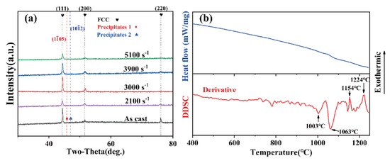
Figure 1.
(a) XRD pattern of the CoCr0.4NiSi0.3 alloy before and after dynamic compression. (b) DSC curves of the CoCr0.4NiSi0.3 alloy in as-cast state.
Figure 2 presents the SEM image analysis and corresponding chemical compositions (at.%) of the alloy pre- and post-dynamic compression. Specifically, Figure 2a showcases polygonal equiaxed grain morphologies prior to dynamic compression, while Figure 2b reveals micropores at triple grain boundary junctions of elongated grains under a strain rate of 3900 s−1 after impact. The energy dispersive spectroscopy presented in Figure 2c reveals a comparison of chemical compositions between intergranular and transgranular regions, indicating a uniform distribution of all elements within the grains prior to impact. However, Figure 2d demonstrates the presence of eutectic morphology second-phase precipitates composed of Si and Ni at grain boundaries after dynamic compression. The mixing enthalpy between Si and Ni is –40 kJ/mol, which is the most negative among all principal elements in the alloy, indicating the second phases readily formed by Ni and Si. Since dynamic compression leads to both localized temperature rise due to adiabatic shear and high stress gradient within the specimens, it promotes atomic diffusion of Si along the grain boundaries, creating kinetically suitable conditions for precipitate formation.
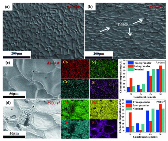
Figure 2.
Microstructure of the CoCr0.4NiSi0.3 alloy (a) as-cast, (b) at a strain rate of 3900 s−1. The chemical compositions and distribution of CoCr0.4NiSi0.3 alloy (c) as-cast state and (d) at a strain rate of 3900 s−1. The blue and red squares in (c) and (d) respectively represent the areas of composition analysis in transgranular and intergranular, respectively.
The high-resolution transmission electron microscopy (HRTEM) images in Figure 3 reveal the presence of lamellar HCP structure precipitates within the sub-grain boundaries of the as-cast MEA. The enlarged HRTEM images of area A and B in Figure 3a, displayed in Figure 3b and Figure 3c, respectively, exhibit nano-scale HCP precipitates in gray-black and bright grey. The fast Fourier transformed (FFT) images of area A and B in Figure 3a, shown in Figure 3d and Figure 3f, respectively, illustrate the FCC matrix along with two HCP precipitates exhibiting a slight lattice mismatch. The inverse fast Fourier transformed (IFFT) images corresponding to the crystallographic plane (002) of areas A and B are illustrated in Figure 3e and Figure 3g, respectively. These two HCP precipitates are identified as a eutectic structure consisting of Ni31Si12 (gray-black region) and Ni2Si (bright grey region), as depicted in Figure 3e and Figure 3g [34]. Moreover, intricate lamellar precipitates can be observed on the IFFT image corresponding to the (–111) plane in area B.
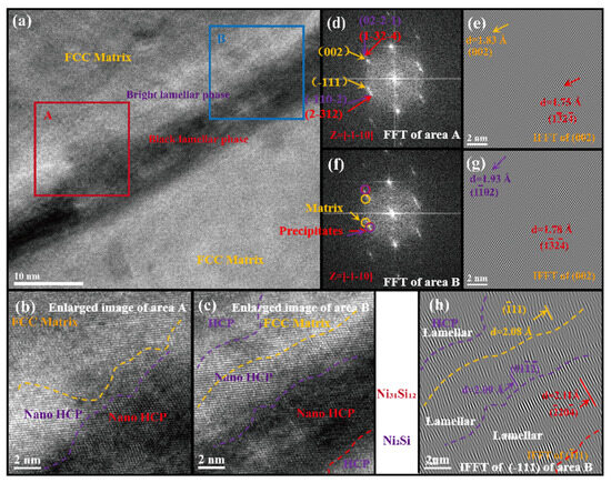
Figure 3.
(a) The HRTEM image shows the sub-grain boundaries of the as-cast MEA. The enlarged HRTEM images display HCP precipitates in (b) area A and (c) area B. The FFT images show the FCC matrix and HCP precipitates in (d) area A and (f) area B. The IFFT images corresponding to the (002) plane show the matrix and precipitates in (e) area A and (g) area B. (h) The IFFT image corresponding to (–111) plane in area B displays lamellar precipitates.
3.2. Dynamic Mechanical Properties
The true stress-strain curves of CoCr0.4NiSi0.3 alloy under dynamic compression at strain rates of 2100, 3000, 3900, and 5100 s−1 are depicted in Figure 4a. By fitting the engineering stress-strain curve during elastic deformation at different strain rates, the dynamic compressive yield strength (σy) was determined to be 811 MPa, 849 MPa, 919 MPa, and 942 MPa at strain rates of 2100 s−1, 3000 s−1, 3900 s−1, and 5100 s−1, respectively, as shown in Figure 4a. The stress drop observed at the termination of each true stress-strain curve in Figure 4a is believed to arise from abrupt interrupted compression occurring within a time frame of approximately 120 μs, adjusted by zeroing as illustrated in Figure 4b. The observed phenomenon bears resemblance to artifacts that are induced by the utilization of stop blocks The observed phenomenon bears resemblance to artifacts that are induced by the utilization of stop blocks [35]. Consequently, the examined specimens exhibit respective true strains of 0.17, 0.25, 0.35, and 0.50 with elevated strain rates. The initial time of stress collapse following dynamic compression at various strain rates, as indicated by red dashed lines and arrows in Figure 4a, is depicted in Figure 4b. This stress collapse phenomenon is attributed to the activation of deformation twins, which significantly contribute to deformation with elevated strain rates [15]. The occurrence of twin nucleation takes place once the stress surpasses the critical resolved shear stress (CRSS) required for twinning [15]. The CRSS, which is observed at the initial peak of each curve in Figure 4b, exhibits an increase with elevated strain rates. The onset time of stress collapse increases with strain rates, ranging from 27 to 87 μs as the strain rate increases from 2100 s−1 to 5100 s−1.
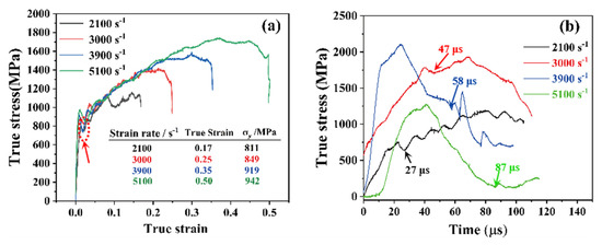
Figure 4.
(a) SHPB test pattern of the CoCr0.4NiSi0.3 alloy. (b) The initial time of stress collapse after dynamic compression at different strain rates adjusted by zeroing.
Deformation primarily relies on dislocation slip during plastic deformation. The experimental data in copper predominantly indicates that the dislocation drag mechanism acts as the rate-limiting factor above strain rates of 103 s−1, while the flow stress is determined by the damping forces exerted by dislocations at high plastic strain rates [36]. Furthermore, molecular dynamics simulation is employed to investigate the interaction mechanism between screw dislocations and the HCP phase in FCC-structured CoCrFeMnNi HEAs [37]. The modes of interaction between dislocations and the HCP phase can be classified as penetration and absorption mechanisms, which are determined by factors such as the thickness of the HCP phase, strain rate, and temperature. The exceptional dynamic yield strength of the alloy in its as-cast state is likely attributed to work hardening resulting from interactions between dislocations and minor HCP precipitates. The stress curves exhibit fluctuations at strain rates of 2100 s−1 and 3000 s−1 in this MEA, as shown in Figure 4b. However, they demonstrate a sharp monotonical increase and decrease during dynamic loading and releasing at strain rates of 3900 s−1 and 5100 s−1. Dislocations become pinched, resulting in work hardening and an increased yield strength under stress loading. They also penetrate the HCP precipitates at elevated strain rates, thereby providing continuous work hardening that contributes to deformation. The dynamic compressive yield strength shows a positive correlation with strain rates at the tested levels, resulting in an increase of approximately 120 MPa. This occurs when dislocations experience constriction, leading to both enhanced work hardening and a higher yield strength under elevated stress.
Σ3n (1 ≤ n ≤ 3) grain boundaries, including Σ3, Σ9, and Σ27, possess low energy and exhibit exceptional material properties [38,39]. The interactions among these boundaries may trigger the regeneration mechanism of Σ3 boundaries with a higher ratio of Σ(9 + 27)/Σ3 [40]. The proportion of Σ3n grain boundaries before and after dynamic compression was calculated using the standard HKL-EBSD Channel 5 software package. Figure 5a illustrates the length fractions of Σ3, Σ(9 + 27), Σ3n, Σ(9 + 27)/Σ3, other low-Σ and overall low-Σ grain boundaries in specimens in the as-cast state and at strain rates of 2100, 3900, and 5100 s−1. Notably, the length fraction of grain boundaries with a Σ value of 3 decreased significantly from 8.16% in the as-cast state to only 0.98% in the specimen tested at a strain rate of 3900 s−1 after dynamic deformation. The detwinning phenomenon, resulting from the formation of partial dislocations and slip at junctions of grain boundaries (GBs) and GB–twin boundaries (TBs), was observed in Σ3n GBs under dynamic loading. This trend is consistent with previous findings [41]. With an increasing strain rate, the proportion of overall low Σ Coincidence Site Lattice (CSL) interfaces (Σ ≤ 29, with a maximum deviation of orientation difference ∆θ ≤ 15°) rose from 1.22% to 1.68%. Similarly, the proportion of other low Σ and Σ(9 + 27) exhibited an upward trend with the increase in strain rate. Figure 5b illustrates grain refinement as strain rates increase. After undergoing dynamic compression, the average diameter of grains experiences a significant reduction from 19.7 to 3.4 µm. Deformation twins are activated and their occurrence increases with higher strain rates and grain refinement, while dislocation slip is impeded and stress becomes concentrated. The twin boundaries serve dual purposes, namely, enhancing the rate of strain hardening and facilitating uniform deformation while delaying the onset of necking [15]. Furthermore, twinning is a prominent deformation mechanism in crystalline materials. The nucleation of microcracks and micropores at specific grain boundaries during blocked deformation twinning requires a critical twin thickness, as demonstrated by the simulation of the wedge disclination quadrupole model [42]. In this study, the proportion of twin boundaries that are rarely observed in FCC metals and alloys reached a maximum of approximately 1.10% at a strain rate of 3900 s−1. Correspondingly, the ratios of Σ(9 + 27)/Σ3 were 0.13, 0.18, and 0.23 at strain rates of 2100 s−1, 3900 s−1, and 5100 s−1 respectively. The lower ratio indicates poor interruption of random boundary networks [40], which suggests decreased connectivity and improved crack resistance. The twins can induce a reorientation effect and facilitate further slip in the alloy [43]. Moreover, they dynamically refine the grain structure through shearing at high strain rates with increasing volume fractions, thereby enhancing its homogeneous deformation ability and plasticity. Therefore, in this study, the Σ3n grain boundaries disrupt the connectivity of general grain boundary networks and give rise to specific three-node structures under dynamic compression. Consequently, crack propagation is impeded, higher mechanical stress is resisted, and both strength and plasticity are simultaneously enhanced.
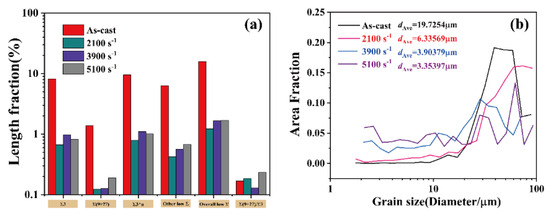
Figure 5.
(a) The length fraction of Σ3n grain boundaries. (b) Grain size distribution by the area fraction before and after dynamic compression.
3.3. Dynamic Recrystallization and Adiabatic Heating
Figure 6a,b depict the EBSD mappings of dynamic recrystallization and strain contour for CoCr0.4NiSi0.3 alloy under a strain rate of 5100 s−1. Cracks, which are likely to have developed in the compression direction due to shear banding, can be identified on the surface of the cross section. As indicated by the arrows in Figure 6a, there are only a small number of recrystallized grains located close to cracks and micropores within the specimen. Dynamic recrystallization mainly takes place around grain boundaries where stress concentrates, indicating that an adiabatic temperature increase is usually not typically associated with it. The microstructure observed in specimens following dynamic compression mostly comprises distorted grains, as demonstrated by Figure 2b. When the strain rate is in the range of 2100 to 5100 s−1, the percentage of deformed grains varies from 79.98% to 87.21% as illustrated in Figure 6c, while the proportion of dynamically recrystallized grains increases from 1.75% to 2.87% with an elevated strain rate.
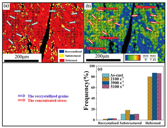
Figure 6.
(a) The dynamic recrystallization and (b) strain contour of EBSD mappings of the CoCr0.4NiSi0.3 alloy at a strain rate of 5100 s−1. (c) The area fraction of recrystallized, sub-structured, and distorted grains before and after dynamic compression.
During dynamic deformation, it is essential to consider adiabatic heating as it can lead to alloy softening and consequent strength degradation. An equation can be utilized for estimating the temperature increase () during adiabatic deformation at a plastic strain of :
where A, representing the fraction of energy converted to heat, is taken as ~0.9, is the true stress, is the true plastic strain, is the mass density of the alloy (around 7.9 g/cm3), and is the specific heat capacity approximately calculated by atomic ratio at constant volume, with a value around 460 . Therefore, the temperature increases () proportionally with increasing strain rates as described in Equation (1). The maximum adiabatic temperature increase is estimated to be 117 K when compressed at a rate of 5100 s−1, resulting in an instantaneous rise to 416 K. According to the previous DSC analysis, it can be inferred that the melting temperature of the alloy is not lower than 1523 K (1250 ℃), indicating that adiabatic heating may occur below the dynamic recrystallization temperature, which is not lower than 609 K (0.4 ). Based on these facts, it can be argued that dynamical recrystallization occurs in many studies due to thermal softening effects leading to shear localization and the formation of ASBs during dynamic deformations [44,45]. Furthermore, the present study suggests that a temperature rise is unlikely to significantly affect the yield strength of the alloy.
3.4. Texture Evolution
The evolution of textures in CoCr0.4NiSi0.3 alloy under different strain rates was further investigated by analyzing relevant ODF-sections. The prominent textures in ideal FCC alloys at φ2 = 0°, 45°, and 65° are given in Figure 7, followed by ODF-sections and corresponding Miller indices of CoCr0.4NiSi0.3 alloy before and after dynamic compression at the corresponding Euler angle. Figure 7 shows a prominent α-fiber in the as-cast state, mainly the {110}<115> Goss/Brass texture with weaker intensities of {110}<112> Brass and {110}<111> Goss/Brass, which can be clearly observed in the φ2 = 45° section. After dynamic compression at a strain rate of 2100 s−1, the intensity of {001}<110> R-Cube texture increases. Recrystallization texture with {110}<110> R-Goss component is observed from the φ2 = 0° and 45° sections, along with deformation textures of {111}<112> F and {111}<110> E components. The {110}<110> R-Goss texture disappears at a strain rate of 3900 s−1, and mainly {111}<112> F texture remains when the strain rate increases to 5100 s−1. It can be inferred that nanotwins initiate multi-slip systems and facilitate deformation by changing the orientation with the stress concentration under dynamic loading conditions. The dynamic impact properties of the MEAs exhibit anisotropy in various orientations. The texture eventually evolves into a stable {111}<112> crystallographic orientation under elevated strain rates, indicating the development of a preferred alignment and the manifestation of both elastic and plastic anisotropy following dynamic loading. Lamellar nanotwins can be identified before and after dynamic compression in Figure 8. The volume of nanotwins increases dramatically after dynamic compression. This improves plastic deformation capacity.
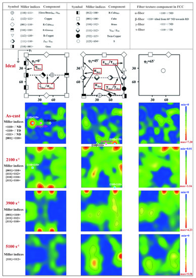
Figure 7.
φ2 = 0°, 45°, and 65° ODF-sections of the CoCr0.4NiSi0.3 alloy in as-cast state and dynamically compressed at strain rates of 2100, 3900, and 5100 s−1.
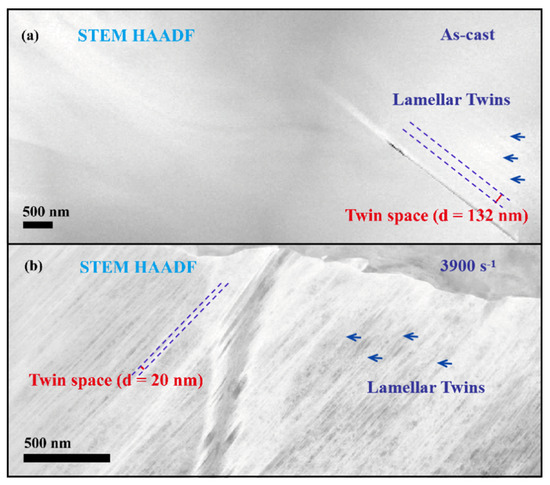
Figure 8.
The HAADF STEM images exhibit (a) lamellar twins before deformation and (b) lamellar twins after dynamic compression at a strain rate of 3900 s−1.
The mapping areas are illustrated in Figure 9a–d. The grain numbers were determined by the intercept length method using OIM software, and there were 1743, 2828, 3845, and 5143 grains within the corresponding EBSD mapping area grids (µm) of 556 × 423, 568 × 423, 473 × 352, and 467 × 350 for specimens subjected to as-cast conditions and strain rates of 2100 s−1, 3900 s−1, and 5100 s−1, respectively. Edge grains were accounted for as half a grain in the analysis. The EBSD mapping of grain numbers before and after dynamic compression reveals an increase in the number of grains experiencing elevated strain rates, indicating that the grains underwent further fragmentation and refinement, as illustrated in Figure 5b. Figure 9e–h show the texture components of the MEA before and after dynamic compression shown in Figure 7. With increasing of the strain and evolution of the textures after dynamic compression, the geometrically necessary dislocations (GNDs) and corresponding b, which is the magnitude of Burgers vector and represents the lattice distortion, vary with strain rates.
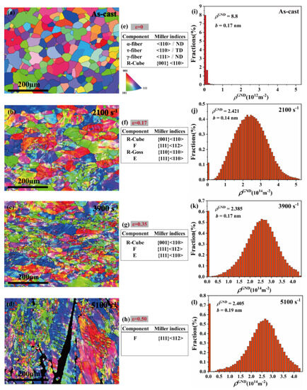
Figure 9.
EBSD-IPFs maps of (a) as-cast, and dynamically compressed at a strain rate of (b) 2100 s−1, (c) 3900 s−1, and (d) 5100 s−1. Texture evolution of (e) as-cast, (f) 2100 s−1, (g) 3900 s−1, and (h) 5100 s−1. The frequency histograms show GND density in the state of (i) as-cast, (j) 2100 s−1, (k) 3900 s−1, and (l) 5100 s−1.
The GND density can be introduced to calculate dislocation activities and storage during deformation. The GND density can be mathematically expressed as [46,47]:
where can be obtained and analyzed by HKL-EBSD Channel 5. (Kernel average misorientation) represents the average KAM of the selected area, which is obtained by the OIM software, is the step size, and b is the magnitude of the Burgers vector. For the purpose of computing the Burgers vector, Equation (2) can be transformed and approximated as:
Based on calculations, the Burgers vector magnitude of the as-cast CoCr0.4NiSi0.3 alloy is determined to be 0.17 nm. The frequency histograms depicting GND before and after compression tests are illustrated in Figure 9i–l. The average values of specimens in their as-cast state and at strain rates of 2100, 3900, and 5100 s−1 are 8.8 × 10¹² m−2, 2.421 × 10¹⁴ m−2, 2.385 × 10¹⁴ m−2, and 2.405 × 10¹⁴ m−2, respectively. When specimens are dynamically loaded, heterogeneous deformation occurs followed by dislocations concentrated on the grain boundaries. The generated GND adapts to the strain across the heterogeneous interface and maintains the continuity of the deformation gradient between grains. In this study, the GND multiplies greatly during dynamic compression tests. According to Equation (3), the Burgers vector exhibits a range of 0.14~0.19 nm with increasing strain rates, likely due to the texture evolution and local strain changes following dynamic compression at varying rates resulting in more severe lattice distortion. The degree of plastic deformation characterizing this process increases by nearly two orders of magnitude before stabilizing within a small fluctuation range after dynamic loading.
In this study, the lattice parameter of CoCr0.4NiSi0.3 is approximately 0.36 nm. Under dynamic compression deformation in an FCC alloy as the major phase, dislocation dissociation and synthetic reactions satisfy both geometric and energy conditions, which can be deduced as:
The distinct slip modes of dislocations correspond to different strain rates during dynamic compression, as inferred from the analysis of Miller indices in Figure 7 and the magnitude of the Burgers vector depicted in Figure 9i–l. Specifically, at a strain rate of 2100 s−1, the average Burgers vector is 0.14 nm, which closely approximates the Burgers vector of Shockley partial dislocations forming {111}<112> F texture (calculated as 0.15 nm by <112>). The magnitude is smaller than the shortest translation vector in the {111} slip plane, resulting in the occurrence of SFs. This leads to a disruption of the normal stacking sequence of packed planes and ultimately results in a structure containing layers of HCP within an FCC matrix [28]. The deduction is further supported by the HRTEM images of a specimen subjected to compression at a strain rate of 3900 s−1, as depicted in Figure 10.
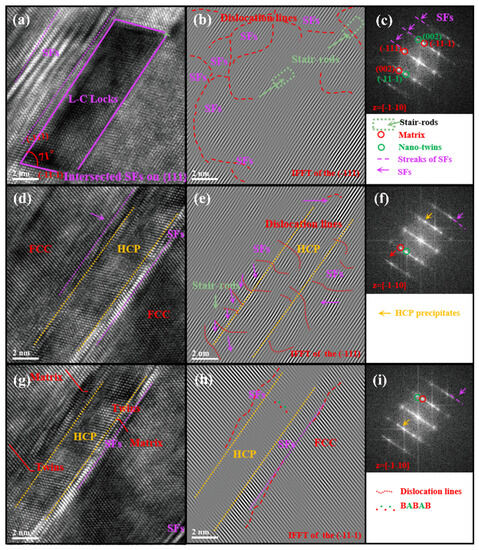
Figure 10.
(a) HRTEM image of the MEA at a strain rate of 3900 s−1. (b) IFFT corresponding to (−111) of (a). (c) FFT of (a) showing SFs, twins. (d) HRTEM image of HCP precipitates from FCC matrix. (e) IFFT corresponding to (−111) of (d). (f) FFT of (d) showing FCC matrix, HCP precipitates and SFs. (g) HRTEM image shows HCP precipitates accompanied by SFs and nanotwins. (h) IFFT corresponding to (−11–1) of (g). (i) FFT of (g) showing the formation of nano-scaled HCP precipitates and twins at a strain rate of 3900 s−1.
Figure 10a illustrates the presence of L-C locks accompanied by SFs, while Figure 10b represents the IFFT image corresponding to (–111) of Figure 10a, revealing the existence of dislocations, SFs, and stair-rods. The L-C locks depicted in Figure 10a can be formed through the gliding of mobile interfacial dislocations, resulting in either thickening or thinning of stacking faults on distinct {111} slip planes [15,48,49] during dynamic compression, as further illustrated in Figure 10b. When the two leading partials interact with each other, a sessile stair-rod dislocation is formed to create L-C locks [49]. L-C locks can function as Frank–Read sources for dislocation multiplication, leading to work hardening [48]. The presence of stair-rods, as demonstrated in Figure 10a,b,d, is likely to be the primary factor contributing to the significant increase in the observed yield strength of this alloy. The occurrence of L-C locks and stair-rods resulting from dynamic compression enhances the structural stability of the alloy, rendering it more resistant to dissociation and creating stronger barriers to dislocation slip. The configuration displayed in Figure 10a,d,g is formed by the dynamic overlapping of two extended partial dislocations with SFs on adjacent slip planes, where the two SFs only partially overlap and are accompanied by twins, resulting in a {111}<112> texture. Figure 10c illustrates the FFT image of Figure 10a, providing further confirmation of the presence of twins and SFs. The IFFT image corresponding to (–111) of Figure 10d is depicted in Figure 10e, while the IFFT image corresponding to (–11–1) of Figure 10g is displayed in Figure 10h. Figure 10f and Figure 10i represent the FFT of Figure 10d and Figure 10g, respectively. These figures visually demonstrate the presence of HCP precipitates within the FCC matrix. After dynamic loading, atomic layers of HCP precipitates with SFs and twins are formed in the FCC matrix. These HCP laths have a width less than 10 nm, as depicted in Figure 10g,h. The nucleation of HCP laths typically occurs adjacent to the deformation twins in the FCC matrix, indicating a strong correlation between these two microstructural features [50]. The nanotwins as shown in Figure 10g are a result of SF-induced nanotwinning, which arises from an extrinsic stacking fault caused by two consecutive intrinsic stacking faults interacting on mobile interfacial dislocations present on {111} planes. Nanotwin formation occurs once three or more intrinsic stacking faults appear successively on {111} planes [15]. Another nucleation mechanism of nanotwin in CoCrNi MEA involves the consumption of HCP phases [51], as demonstrated through simulation using the kinetic Monte Carlo method. Figure 10d,g depict the process of nucleating nano-HCP precipitates within the grain. The precipitation of HCP nucleated in CoCrNi-based MEA under dynamic loading can be attributed to various mechanisms. The nucleation mechanisms of SFs and twin-induced HCP structures, respectively, suggest a combined mechanism for the formation of nanotwins in this alloy, involving both FCC/SF-nanotwins and HCP-nanotwins. The volume of HCP does not exhibit an increase after dynamic loading, as depicted in Figure 1a. This observation contradicts the nucleation mechanism associated with HCP. Additionally, Figure 2d and Figure 3c visually illustrate the segregation of HCP precipitates along grain boundaries prior to deformation, while Figure 10 portrays the HCP transition occurring within the crystal subsequent to dynamic compression. Therefore, it can be inferred that the nucleation of HCP phases from SFs [15] and their consumption by nanotwins [51], induced by dynamic compression, contribute to the increase in twin ratio with elevated strain rates in this study. The presence of HCP precipitates under dynamic loading in this MEA demonstrates a complex interplay among SFs, nanotwins, L-C locks, stair-rods, and the process of HCP transformations. The space between nanotwins, as shown in Figure 8 before and after dynamic compression, signifies that the tolerance limit has not been reached. Furthermore, the absence of adiabatic shear bands in both pre- and post-impact specimens suggests that the utilization of MEAs as energy-absorbing materials is viable within the realm of high-speed impact.
Therefore, the evolution of texture is believed to be associated with variations in deformation configuration after dynamic loading. The superior mechanical properties of strength and plasticity under dynamic loading are attributed to the comprehensive microstructural evolution involving SFs, deformation twins, FCC-HCP phase transformation, and stair-rods [30,52]. It can be deduced that the deformation process is roughly divided into three stages: dislocation slip, deformation nanotwins accompanied by SFs, and displacive phase transition induced by higher stress loading. As the strain rates increase, the deformation mechanism shifts from dislocation slip to the formation of a complex microstructure comprising deformation nanotwins accompanied by SFs, L-C locks, stair-rods, and displacive phase transition as depicted in Figure 10. In addition, it can be inferred that the recrystallization is a result of HCP precipitates in the alloy. The crystal nuclei are formed through stress-induced displacive phase transition.
4. Conclusions
In the present study, XRD, DSC, SEM, EBSD, and TEM characterizations were employed to investigate the microstructure, mechanical properties, and texture evolution of the CoCr0.4NiSi0.3 alloy. Main conclusions can be drawn as follows:
- (1)
- Strain rate exerts a significant influence on the dynamic yield strength of as-cast CoCr0.4NiSi0.3 alloy under dynamic compression. At strain rates of 2100, 3000, 3900, and 5100 s−1, corresponding true strains of 0.17, 0.25, 0.35, and 0.50, respectively, result in dynamic compressive strengths of 811 MPa, 849 MPa, 919 MPa, and 942 MPa. The exceptional dynamic yield strength can be attributed to comprehensive intrinsic factors associated with the chemical composition of the alloy.
- (2)
- The adiabatic heating triggered by dynamic compression is ~117 K at strain rates of ~5100 s−1, and is not typically associated with dynamic recrystallization. The FCC-HCP transformation in the matrix observed through HRTEM is considered a stress-induced displacive phase transition. The HCP precipitates nucleate from the SFs and nanotwins induced by dynamic loading in this MEA, while they can also be consumed by twins under stress.
- (3)
- During the dynamic compression test, microcracks were exclusively observed at a strain rate of 5100 s−1. Conversely, micropores rather than microcracks emerged on the specimens subjected to other strain rates (less than 5100 s−1). The specific three-nodes of Σ3n grain boundaries that formed in the tested specimens impeded crack propagation, resisted higher mechanical stress, and altered orientations.
- (4)
- The deformation mode of CoCr0.4NiSi0.3 alloy can be roughly divided into three stages: dislocation slip, deformation nanotwins accompanied by SFs, and displacive phase transition under dynamic loading at room temperature. The superior mechanical properties of strength and plasticity are attributed to a deformation mechanism that involves the shifts from dislocation slip to the formation of intricate arrangements comprising deformation nanotwins accompanied by SFs, L-C locks, stair-rods, and displacive phase transition at elevated strain rates.
Author Contributions
Conceptualization, L.Z. and W.Z.; methodology, L.Z.; software, L.Z.; validation, L.Z., W.Z., L.C., F.L. and H.Z.; formal analysis, L.Z.; investigation, X.W. and G.Z.; resources, L.Z.; data curation, L.Z. and W.Z.; writing—original draft preparation, L.Z.; writing—review and editing, L.Z. and W.Z.; visualization, L.Z.; supervision, F.L., L.C., H.Z. and W.Z.; project administration, H.Z.; funding acquisition, L.Z. All authors have read and agreed to the published version of the manuscript.
Funding
The authors would like to gratefully acknowledge the support of the Basic Scientific Research Projects for colleges and universities (General Programs), funded by the Education Department of Liaoning Province of China (No. LJKMZ20220592).
Data Availability Statement
Not applicable.
Conflicts of Interest
The authors declare no conflict of interest.
References
- Yeh, J.W.; Chen, S.K.; Lin, S.J.; Gan, J.Y.; Chin, T.S.; Shun, T.T.; Tsau, C.-H.; Chang, S.-Y. Nanostructured High-entropy alloys with multiple principal elements: Novel Alloy Design Concepts and Outcomes. Adv. Eng. Mater. 2004, 6, 299–303. [Google Scholar] [CrossRef]
- Cantor, B.; Chang, I.T.H.; Knight, P.; Vincent, A.J.B. Microstructural development in equiatomic multicomponent alloys. Mater. Sci. Eng. A 2004, 375–377, 213–218. [Google Scholar] [CrossRef]
- Gao, M.C.; Gao, P.; Hawk, J.A.; Ouyang, L.; Alman, D.E.; Widom, M. Computational modeling of high-entropy alloys: Structures, thermodynamics and elasticity. J. Mater. Res. 2017, 32, 3627–3641. [Google Scholar] [CrossRef]
- George, E.P.; Raabe, D.; Ritchie, R.O. High-entropy alloys. Nat. Rev. Mater. 2019, 4, 515–534. [Google Scholar] [CrossRef]
- Senkov, O.N.; Wilks, G.B.; Miracle, D.B.; Chuang, C.P.; Liaw, P.K. Refractory high-entropy alloys. Intermetallics 2010, 18, 1758–1765. [Google Scholar] [CrossRef]
- Senkov, O.N.; Wilks, G.B.; Scott, J.M.; Miracle, D.B. Mechanical properties of Nb25Mo25Ta25W25 and V20Nb20Mo20Ta20W20 refractory high entropy alloys. Intermetallics 2011, 19, 698–706. [Google Scholar] [CrossRef]
- Gludovatz, B.; Hohenwarter, A.; Catoor, D.; Chang, E.H.; George, E.P.; Ritchie, R.O. A fracture-resistant high-entropy alloy for cryogenic applications. Science 2014, 345, 1153–1158. [Google Scholar] [CrossRef] [PubMed]
- Gludovatz, B.; Hohenwarter, A.; Thurston, K.V.; Bei, H.; Wu, Z.; George, E.P.; Ritchie, R.O. Exceptional damage-tolerance of a medium-entropy alloy CrCoNi at cryogenic temperatures. Nat. Commun. 2016, 7, 10602. [Google Scholar] [CrossRef] [PubMed]
- Wu, Z.; Bei, H.; Pharr, G.M.; George, E.P. Temperature dependence of the mechanical properties of equiatomic solid solution alloys with face-centered cubic crystal structures. Acta Mater. 2014, 81, 428–441. [Google Scholar] [CrossRef]
- Li, W.D.; Chen, S.Y.; Liaw, P.K. Discovery and design of fatigue-resistant high-entropy alloys. Scr. Mater. 2020, 187, 68–75. [Google Scholar] [CrossRef]
- Chuang, M.H.; Tsai, M.H.; Wang, W.R.; Lin, S.J.; Yeh, J.W. Microstructure and wear behavior of AlxCo1.5CrFeNi1.5Tiy high-entropy alloys. Acta Mater. 2011, 59, 6308–6317. [Google Scholar] [CrossRef]
- Öztürk, S.; Alptekin, F.; Önal, S.; Sünbül, S.E.; Şahin, Ö.; İçin, K. Effect of titanium addition on the corrosion behavior of CoCuFeNiMn high entropy alloy. J. Alloys Compd. 2022, 903, 163867. [Google Scholar] [CrossRef]
- Yan, X.H.; Li, J.S.; Zhang, W.R.; Zhang, Y. A brief review of high-entropy films. Mater. Chem. Phys. 2018, 210, 12–19. [Google Scholar] [CrossRef]
- Granberg, F.; Nordlund, K.; Ullah, M.W.; Jin, K.; Lu, C.; Bei, H.; Wang, M.; Djurabekova, F.; Weber, J.; Zhang, Y. Mechanism of radiation damage reduction in equiatomic multicomponent single phase alloys. Phys. Rev. Lett. 2016, 116, 1. [Google Scholar] [CrossRef]
- Xu, D.F.; Wang, M.L.; Li, T.X.; Wei, X.S.; Lu, Y.P. A critical review of the mechanical properties of CoCrNi-based medium-entropy alloys. Microstructures 2022, 2, 2022001. [Google Scholar] [CrossRef]
- Yin, B.; Curtin, W.A. First-principles-based prediction of yield strength in the RhIrPdPtNiCu high-entropy alloy. NPJ Comput. Mater. 2019, 5, 14. [Google Scholar] [CrossRef]
- Lu, Z.P.; Wang, H.; Chen, M.W.; Baker, I.; Yeh, J.W.; Liu, C.T.; Nieh, T.G. An assessment on the future development of high-entropy alloys: Summary from a recent workshop. Intermetallics 2015, 66, 67–76. [Google Scholar] [CrossRef]
- Slone, C.E.; Chakraborty, S.; Miao, J.; George, E.P.; Mills, M.J.; Niezgoda, S.R. Influence of deformation induced nanoscale twinning and FCC-HCP transformation on hardening and texture development in medium-entropy CrCoNi alloy. Acta Mater. 2018, 158, 38–52. [Google Scholar] [CrossRef]
- Chang, H.; Zhang, T.W.; Ma, S.G.; Zhao, D.; Xiong, R.L.; Wang, T.; Li, Q.; Wang, Z.H. Novel Si-added CrCoNi medium entropy alloys achieving the breakthrough of strength-ductility trade-off. Mater. Des. 2021, 197, 109202. [Google Scholar] [CrossRef]
- Zhang, T.W.; Ma, S.G.; Zhao, D.; Wu, Y.C.; Zhang, Y.; Wang, Z.H.; Qiao, J.W. Simultaneous enhancement of strength and ductility in a NiCoCrFe high-entropy alloy upon dynamic tension: Micromechanism and constitutive modelling. Int. J. Plast. 2020, 124, 226–246. [Google Scholar] [CrossRef]
- Zhang, L.S.; Ma, G.L.; Fu, L.C.; Tian, J.Y. Recent progress in high-entropy alloys. Adv. Mater. Res. 2013, 631–632, 227–232. [Google Scholar] [CrossRef]
- Huang, S.; Li, W.; Lu, S.; Tian, F.; Shen, J.; Holmström, E.; Vitos, L. Temperature dependent stacking fault energy of FeCrCoNiMn high entropy alloy. Scr. Mater. 2015, 108, 44–47. [Google Scholar] [CrossRef]
- Laplanche, G.; Kostka, A.; Reinhart, C.; Hunfeld, J.; Eggeler, G.; George, E.P. Reasons for the superior mechanical properties of medium-entropy CrCoNi compared to high-entropy CrMnFeCoNi. Acta Mater. 2017, 128, 292–303. [Google Scholar] [CrossRef]
- Liu, W.H.; Wu, Y.; He, J.Y.; Nieh, T.G.; Lu, Z.P. Grain growth and the hall–petch relationship in a high-entropy FeCrNiCoMn alloy. Scr. Mater. 2013, 68, 526–529. [Google Scholar] [CrossRef]
- Otto, F.; Dlouhý, A.; Somsen, C.; Bei, H.; Eggeler, G.; George, E.P. The influences of temperature and microstructure on the tensile properties of a CoCrFeMnNi high-entropy alloy. Acta Mater. 2013, 61, 5743–5755. [Google Scholar] [CrossRef]
- Laplanche, G.; Kostka, A.; Horst, O.M.; Eggeler, G.; George, E.P. Microstructure evolution and critical stress for twinning in the CrMnFeCoNi high-entropy alloy. Acta Mater. 2016, 118, 152–163. [Google Scholar] [CrossRef]
- Jo, Y.H.; Jung, S.; Choi, W.M.; Sohn, S.S.; Kim, H.S.; Lee, B.J.; Kim, N.J.; Lee, S. Cryogenic strength improvement by utilizing room-temperature deformation twinning in a partially recrystallized VCrMnFeCoNi high-entropy alloy. Nat. Commun. 2017, 8, 1–8. [Google Scholar] [CrossRef]
- Lin, Q.Y.; Liu, J.P.; An, X.H.; Wang, H.; Zhang, Y.; Liao, X.Z. Cryogenic-deformation-induced phase transformation in an FeCoCrNi high-entropy alloy. Mater. Res. Lett. 2018, 6, 236–243. [Google Scholar] [CrossRef]
- Liu, T.K.; Wu, Z.; Stoica, A.D.; Xie, Q.; Wu, W.; Gao, Y.F.; Bei, H.; An, K. Twinning-mediated work hardening and texture evolution in CrCoFeMnNi high entropy alloys at cryogenic temperature. Mater. Des. 2017, 131, 419–427. [Google Scholar] [CrossRef]
- Chen, Y.J.; Chen, D.K.; An, X.H.; Zhang, Y.; Zhou, Z.F.; Lu, S.; Munroe, P.; Zhang, S.; Liao, X.Z.; Zhu, T.; et al. Unraveling dual phase transformations in a CrCoNi medium-entropy alloy. Acta Mater. 2021, 215, 117112. [Google Scholar] [CrossRef]
- Gao, P.; Ma, Z.H.; Gu, J.; Ni, S.; Suo, T.; Li, Y.L.; Song, M.; Mai, Y.-W.; Liao, X.Z. Exceptional high-strain-rate tensile mechanical properties in a CrCoNi medium-entropy alloy. Sci. China Mater. 2021, 65, 811–819. [Google Scholar] [CrossRef]
- Li, Z.; Zhao, S.; Alotaibi, S.M.; Liu, Y.; Wang, B.; Meyers, M.A. Adiabatic shear localization in the CrMnFeCoNi high-entropy alloy. Acta Mater. 2018, 151, 424–431. [Google Scholar] [CrossRef]
- Ma, Y.; Yuan, F.; Yang, M.; Jiang, P.; Ma, E.; Wu, X. Dynamic shear deformation of a CrCoNi medium-entropy alloy with heterogeneous grain structures. Acta Mater. 2018, 148, 407–418. [Google Scholar] [CrossRef]
- Lu, Y.P.; Li, G.B.; Du, Y.Y.; Ji, Y.S.; Jin, Q.; Li, T.J. Electromagnetic modification of faceted-faceted NI31Si12-Ni2Si eutectic alloy. Chin. Sci. Bull. 2012, 57, 1595–1599. [Google Scholar] [CrossRef][Green Version]
- Holzer, A.J.; Brown, R.H. Mechanical behavior of metals in dynamic compression. J. Eng. Mater. Technol. 1979, 101, 238–247. [Google Scholar] [CrossRef]
- Follansbee, P.S.; Weertman, J. On the question of flow stress at high strain rates controlled by dislocation viscous flow. Mech. Mater. 1982, 1, 345–350. [Google Scholar] [CrossRef]
- Li, R.N.; Song, H.Y.; Xiao, M.X.; An, M.R. Atomic-scale insight into interaction mechanism between screw dislocation and HCP phase in high-entropy alloy. J. Appl. Phys. 2023, 133, 034302. [Google Scholar] [CrossRef]
- Zhu, Y.T.; Liao, X.Z.; Wu, X.L. Deformation twinning in nanocrystalline materials. Prog. Mater. Sci. 2012, 57, 1–62. [Google Scholar] [CrossRef]
- He, W.J.; Hu, R.; Gao, X.Y.; Yang, J.R. Evolution of Σ3n CSL boundaries in Ni-Cr-Mo alloy during aging treatment. Mater. Charact. 2017, 134, 379–386. [Google Scholar] [CrossRef]
- Zhang, X.Y.; Zhao, X.M.; Li, D.F.; Guo, S.L. Relationships between the Σ9 and Σ27 boundaries and the connectivity of random boundary in hastelloy C-276 alloy. Rare Met. Mater. Eng. 2018, 47, 2318–2321. [Google Scholar] [CrossRef]
- Wei, Y.J. The kinetics and energetics of dislocation mediated de-twinning in nano-twinned face-centered cubic metals. Mater. Sci. Eng. A 2011, 528, 1558–1566. [Google Scholar] [CrossRef]
- Luo, J. Study of microcrack nucleation from a blocked twin with the wedge disclination model. Arch. Appl. Mech. 2016, 87, 75–85. [Google Scholar] [CrossRef]
- Husser, E.; Bargmann, S. Modeling twinning-induced lattice reorientation and slip-in-twin deformation. J. Mech. Phys. Solids 2019, 122, 315–339. [Google Scholar] [CrossRef]
- Park, J.M.; Moon, J.; Bae, J.W.; Jang, M.J.; Park, J.; Lee, S.; Kim, H.S. Strain rate effects of dynamic compressive deformation on mechanical properties and microstructure of CoCrFeMnNi high-entropy alloy. Mater. Sci. Eng. A 2018, 719, 155–163. [Google Scholar] [CrossRef]
- Andre, M.M. Dynamic Behavior of Materials; John Wiley & Sons, Inc.: Hoboken, NJ, USA, 1994. [Google Scholar]
- Yan, Z.; Wang, D.; He, X.; Wang, W.; Zhang, H.; Dong, P.; Li, C.; Li, Y.; Zhou, J.; Liu, Z.; et al. Deformation behaviors and cyclic strength assessment of AZ31B magnesium alloy based on steady ratcheting effect. Mater. Sci. Eng. A 2018, 723, 212–220. [Google Scholar] [CrossRef]
- Calcagnotto, M.; Ponge, D.; Demir, E.; Raabe, D. Orientation gradients and geometrically necessary dislocations in ultrafine grained dual-phase steels studied by 2D and 3D EBSD. Mater. Sci. Eng. A 2010, 527, 2738–2746. [Google Scholar] [CrossRef]
- Lee, J.H.; Holland, T.B.; Mukherjee, A.K.; Zhang, X.; Wang, H. Direct observation of Lomer-Cottrell locks during strain hardening in nanocrystalline nickel by in situ TEM. Sci. Rep. 2013, 3, 1061. [Google Scholar] [CrossRef]
- Fan, L.; Yang, T.; Zhao, Y.L.; Luan, J.H.; Zhou, G.; Wang, H.; Jiao, Z.B.; Liu, C.-T. Ultrahigh strength and ductility in newly developed materials with coherent nanolamellar architectures. Nat. Commun. 2020, 11, 6240. [Google Scholar] [CrossRef] [PubMed]
- Miao, J.; Slone, C.E.; Smith, T.M.; Niu, C.; Bei, H.; Ghazisaeidi, M.; Pharr, G.M.; Mills, M.J. The evolution of the deformation substructure in a Ni-Co-Cr equiatomic solid solution alloy. Acta Mater. 2017, 132, 35–48. [Google Scholar] [CrossRef]
- Yu, P.; Du, J.-P.; Shinzato, S.; Meng, F.-S.; Ogata, S. Theory of history-dependent multi-layer generalized stacking fault energy—A modeling of the micro-substructure evolution kinetics in chemically ordered medium-entropy alloys. Acta Mater. 2022, 224, 117504. [Google Scholar] [CrossRef]
- Cao, Y.; Ni, S.; Liao, X.Z.; Song, M.; Zhu, Y.T. Structural evolutions of metallic materials processed by severe plastic deformation. Mater. Sci. Eng. R 2018, 133, 1–59. [Google Scholar] [CrossRef]


Disclaimer/Publisher’s Note: The statements, opinions and data contained in all publications are solely those of the individual author(s) and contributor(s) and not of MDPI and/or the editor(s). MDPI and/or the editor(s) disclaim responsibility for any injury to people or property resulting from any ideas, methods, instructions or products referred to in the content. |
© 2023 by the authors. Licensee MDPI, Basel, Switzerland. This article is an open access article distributed under the terms and conditions of the Creative Commons Attribution (CC BY) license (https://creativecommons.org/licenses/by/4.0/).