Article

A Feature of the Horizontal Directional Solidification (HDS) Method Affects the Microstructure of Al2O3/YAG Eutectic Ceramics

by
Juraj Kajan
1,2,*,
Grigori Damazyan
1,
Vira Tinkova
3,
Anna Prnová
4,
Monika Michálková
4,
Peter Švančárek
4,
Tomáš Gregor
1,2,
Alena Akusevich
5,
Branislav Hruška
5 and
Dušan Galusek
4,5
1
AT Crystals s.r.o., Rosinská cesta 9, 010 08 Žilina, Slovakia
2
Institute of Competitiveness, Innovations University of Žilina, Univerzitná 1, 010 26 Žilina, Slovakia
3
Research Centre UNIZA, University of Žilina, Univerzitná 8215/1, 010 26 Žilina, Slovakia
4
Joint Glass Centre of the IIC SAS, TnUAD and FChPT STU, Študentská 2, 911 50 Trenčín, Slovakia
5
FunGlass—Centre for Functional and Surface Functionalized Glass, Alexander Dubček University of Trenčín, Študentská 2, 911 50 Trenčín, Slovakia
*
Author to whom correspondence should be addressed.
Crystals 2024, 14(10), 858; https://doi.org/10.3390/cryst14100858
Submission received: 9 September 2024 / Revised: 26 September 2024 / Accepted: 28 September 2024 / Published: 29 September 2024
(This article belongs to the Special Issue Structural and Characterization of Composite Materials)

Abstract

:
The solidification processes of two compositions, hypereutectic (21.0 mol% Y2O3–79.0 mol% Al2O3) and eutectic (18.5 mol% Y2O3–81.5 mol% Al2O3), were used via the horizontal directional solidification (HDS) method to produce two ingots with dimensions of 317 × 220 × 35 mm and 210 × 180 × 35 mm, respectively. The first ingot was heterogeneous and characterized by a two-layer structure with an expressed horizontal boundary, which is parallel to the solidification direction (an experimental fact observed for the first time), separating eutectic-type ceramics in the upper layer from the lower one containing the YAG dendrites. Considering the heat transfer feature characteristic of the HDS method and its action during the solidification of materials scattering thermal radiation, an explanation of the occurrence of such structure has been proposed. On this basis, the solidification parameters of the second ingot, providing its homogeneous structure, were selected. Characterization of the crystallographic texture and microstructure of both ingots revealed the advantage of the second solidification processing conditions.

1. Introduction

The eutectic ceramic oxides prepared by solidification from the melt are promising structural materials used in the energy sector within an operating temperature range of 1500–1700 °C under conditions of severe mechanical load, where properties such as tensile strength, creep resistance, fracture toughness, etc. are important [1,2].
Waku et al. [3,4] developed binary eutectics called melt-grown composites or directionally solidified eutectic (DSE), the microstructure of which constitutes a continuous three-dimensional network of single-crystalline phases of Al2O3 and oxide compounds interpenetrating without grain boundaries. The microstructure features determine the target properties (mechanical and functional) of DSE oxide materials, and their best manifestation is a homogenous, continuously entangled, three-dimensional interpenetrating network without grains, colonies, and primary phases on both a microscopic and macroscopic scale [5].
Flemings [6] was the first to find that at a high value of G/V ratios (G—thermal gradient, V—cooling rate), the solidification of eutectic structures without primary phases was possible over a wide range of compositions (coupled zone) in which the eutectic could grow faster than primary crystals, thus stifling them. The coupled zone (eutectic range) represents the range of growth conditions ensuring morphologically stable, two-phase growth (coupled growth mode) [7]. That means, on a microscopic scale, the solid–liquid (S/L) interface should advance or grow into the melt as a flat surface, and the two eutectic phases should grow at the same rate (i.e., the coupled growth conditions must be met). In addition, to provide an aligned S/L interface, the absence of constitutional super-cooling is necessary [8,9]. In contrast, the emergence of the primary phase is associated with a competitive growth mode.
Researchers have focused much of their research on determining the optimal parameters for processing DSE to achieve the desired microstructure and homogeneity for specific applications. This includes the Al2O3/Y3Al5O12 (YAG) system, which is widely studied because of its exceptional creep resistance [10,11,12,13]. The question of studying the solidification conditions of ingots in this system and the processing influence on the microstructure has attracted attention for decades until the present day [14,15,16]. The growth methods of these eutectic ceramics can be classified into two groups: (i) unidirectional solidification in a container (Czochralski method [17], Bridgman–Stockbarger technique [18]); (ii) pulling of a solid from a melt meniscus (floating-zone method (LFZ) [19], edge-defined film-growth (EFG) [20], MLS processing [21], and micro-pulling down (l-PD) methods [22]). Higher thermal gradients and higher solidification rates can be achieved using melt meniscus methods. However, these methods do not allow obtaining DSE ceramics with dimensions sufficient for the manufacture of large products, such as gas turbine blades and lining panels for combustion chambers. To obtain larger crystals with a uniform microstructure in a larger volume, the Czochralski technique and the Bridgman methods are more suitable. The authors of publications [23,24] managed to produce Al2O3/YAG eutectic composites with sizes of Ø 30 × 125 mm and Ø 40 × 70 mm, respectively. Neither of them contains colonies or pores, and they both demonstrate excellent strength characteristics at high temperatures. The method of horizontal directional solidification (HDS) was used to further develop bulk samples of Al2O3/YAG DSE ceramics in the form of a plate with dimensions of 180 × 140 × 30 mm [25,26]. The thermal and mechanical properties of samples taken in both longitudinal and transversal sections were studied from room temperature up to 1273 K. The samples had great hardness and fracture toughness (Hv = 18.73–21.8 GPa; KIC = 3.10–3.26 MPa·m1/2). However, the study of the resulting material characteristics was carried out on several small samples cut out of the ingot without examining the microstructure homogeneity of the entire volume.
The HDS method is being used successfully in growing high-temperature oxide crystals, in particular sapphire and yttrium aluminum garnets [27,28,29,30,31,32,33]. Radiative heat transfer (RTH) in crystal growth at high temperatures is an important heat-transfer mechanism, and it is a dominant one for translucent oxide crystals [34]. Internal RTH through the crystallizing material, container, and heat shields depends largely on the relevant optical phenomena in the system (absorption, scattering, refraction, diffuse, and specular reflection). In the context of DSE processing, the scattering and backscattering of radiation fluxes, along with the reduction and alteration of heat flow ratios through the bottom and top surfaces of solidifying eutectic ceramics, can lead to varying solidification conditions and disrupt the homogeneity of the ingot. Thus, the RHT mechanism and a characteristic feature of the HDS method, specifically the asymmetry of the thermal field in the vertical direction, significantly influence the homogeneity of the entire volume of DSE ceramics. From a technological point of view, the heterogeneity of eutectic ceramic ingots can become a serious limitation, reducing the effectiveness of this method in the production of functional materials. Moreover, the aforementioned feature of the HDS method may narrow the width of the eutectic range, as established by the authors [35]. Therefore, the purpose of the work is to obtain the Al2O3/YAG eutectic ceramic ingots by the HDS method using hypereutectic and eutectic initial compositions and characterization of microstructure.

2. Materials and Methods

2.1. Al2O3/YAG Eutectic Ceramics Processing

The commercial powders of Al2O3 (99.99%) and Y2O3 (99.99%) were used for the preparation of raw material at the two compositions: 79.0 mol% Al2O3, 21.0 mol% Y2O3 (hypereutectic) for DSE ingot No. 1 and 81.5 mol% Al2O3, 18.5 mol% Y2O3 (eutectic) for DSE ingot No. 2. First, the Al2O3 and Y2O3 powders were mixed by wet ball milling with ethyl alcohol and a rotation speed of 100 r/min. Then, the homogeneous oxide mixture was formed into pellets by uniaxial pressing at 20 MPa and calcined in a chamber furnace at 1450 °C for 10 h in an air atmosphere. Afterward, the raw material of appropriate composition was charged into molybdenum containers with sizes of 317 × 220 × 55 mm and 210 × 180 × 55 mm for the first and second solidification processes, respectively, using the HDS method.
The processing of Al2O3/YAG eutectic ceramic ingot No. 1 was carried out using a pulling rate of 50 mm/h. The DSE ceramic ingot No. 2 was solidified at the rate of 20 mm/h. The monitoring of the upper SL boundary position was carried out visually, thereby ensuring control of the solidification rate and its compliance with the container pulling rate. The thermal regimes of heating and cooling of the first and second processes were the same. The eutectic melting temperature is 1826 ± 10 °C [36]. The technology used allows you to melt the material and carry out the subsequent crystallization of eutectic ceramics when the melt is overheated by no more than 50 °C, which excludes the possibility of the formation of metastable ceramics [36,37]. We estimated the thermal gradient at 30–40 °C/cm, considering the experience of growing single crystals using the HDS method and the changes in heat transfer characteristics during the crystallization of eutectic structures. After the processing was complete, the ingot was cooled down to 800 °C at a rate of 100 °C/h and then further down to room temperature at a rate of 50 °C/h. Both solidification processes were conducted without a seed crystal and continued up to 80% of the container length in residual pressure in the growth chamber of 1–5·10−5 mbar.

2.2. Characterization

The microstructure characterization was investigated on the samples cut out from the DSE ceramic ingots No. 1 and No. 2 using a scanning electron microscope (SEM, JEOL 7600F). The preparation of the samples for electron backscattering diffraction (EBSD) analysis was carried out in several stages. Initially, for ease of processing, all plates with sizes of 3.43 × 20.15 mm were embedded in the black epoxy hot mounting resin. Further, the samples were polished using the vibratory polisher VibroMet 2 and a Buehler MasterPrep 50 nm theta alumina polishing suspension as a polishing medium for 6 h under a 200 g static load till a glossy surface was achieved. Then, to avoid surface charging, the finely polished samples were coated with 0.2 nm Pt using Qourum Q 150V ES Plus sputtering. EBSD scans were carried out at an accelerating voltage of 30 kV using the NordlysMax2 EBSD camera. The scans were captured using the Oxford Instruments software Aztec 3.1, and the ATEX software (http://www.atex-software.eu/, accessed on 8 September 2024) was applied to analyze the normal EBSD results, such as band contrast maps (BC maps), elemental maps, phase maps, orientation maps, 3D crystal orientation images and inverse polar figures (IPFs) [38]. The phase compositions of the bottom and top ingot layers were estimated using the X-ray diffraction analysis (Panalytical Empyrean DY1098, 45 kV accelerating voltage, Cu Kα radiation with λ = 1.5405 Å). Individual XRD patterns were recorded within 2θ = 10–80°. The diffraction patterns were evaluated with the software HighScore Plus (v.3.0.4, PAN Analytical, The Netherlands) and the COD 2023 database.

3. Results and Discussion

3.1. Al2O3/YAG Eutectic Ceramic Ingot No. 1 (78.5 mol% Al2O3–21.5 mol% Y2O3 Composition)

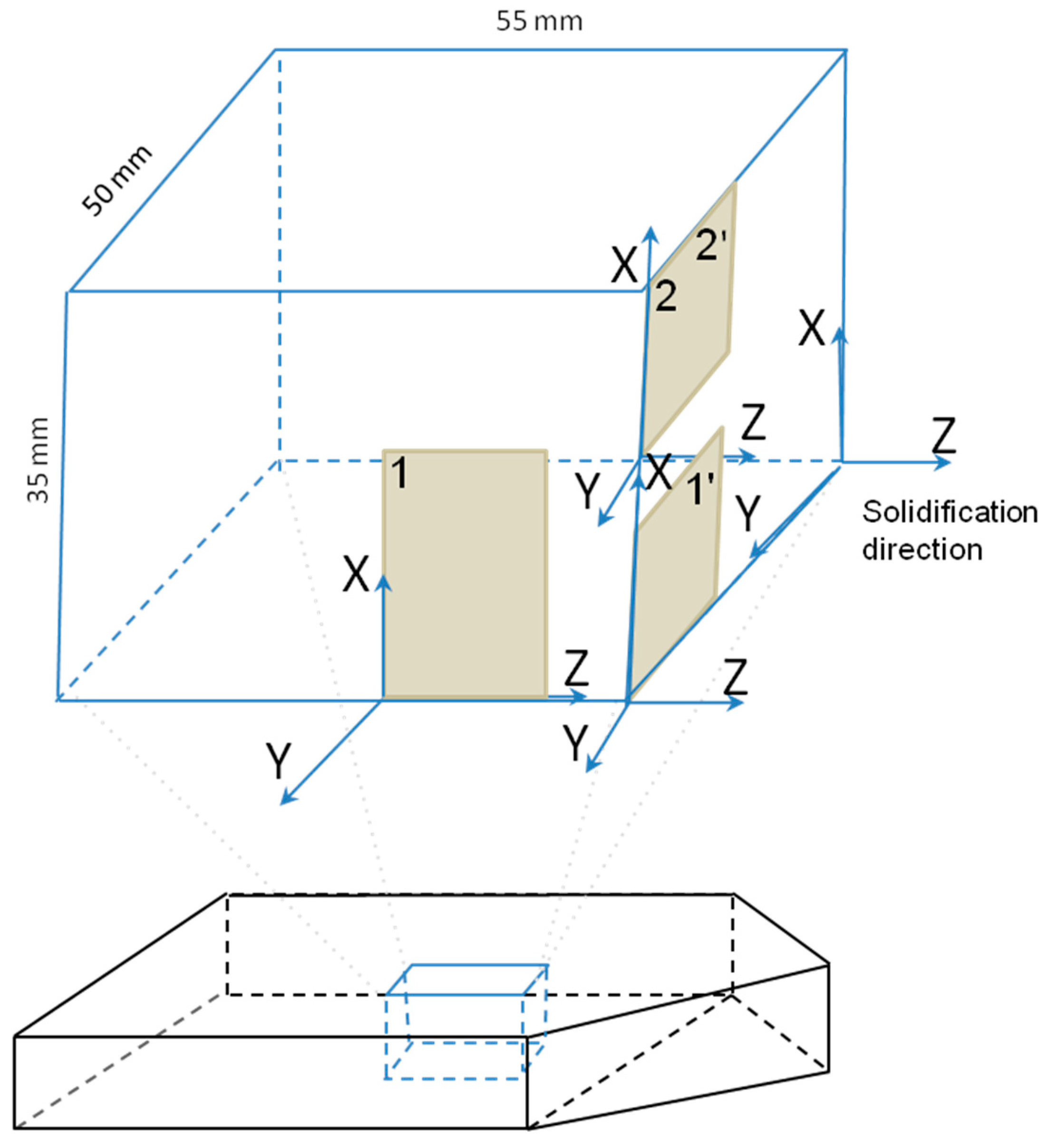
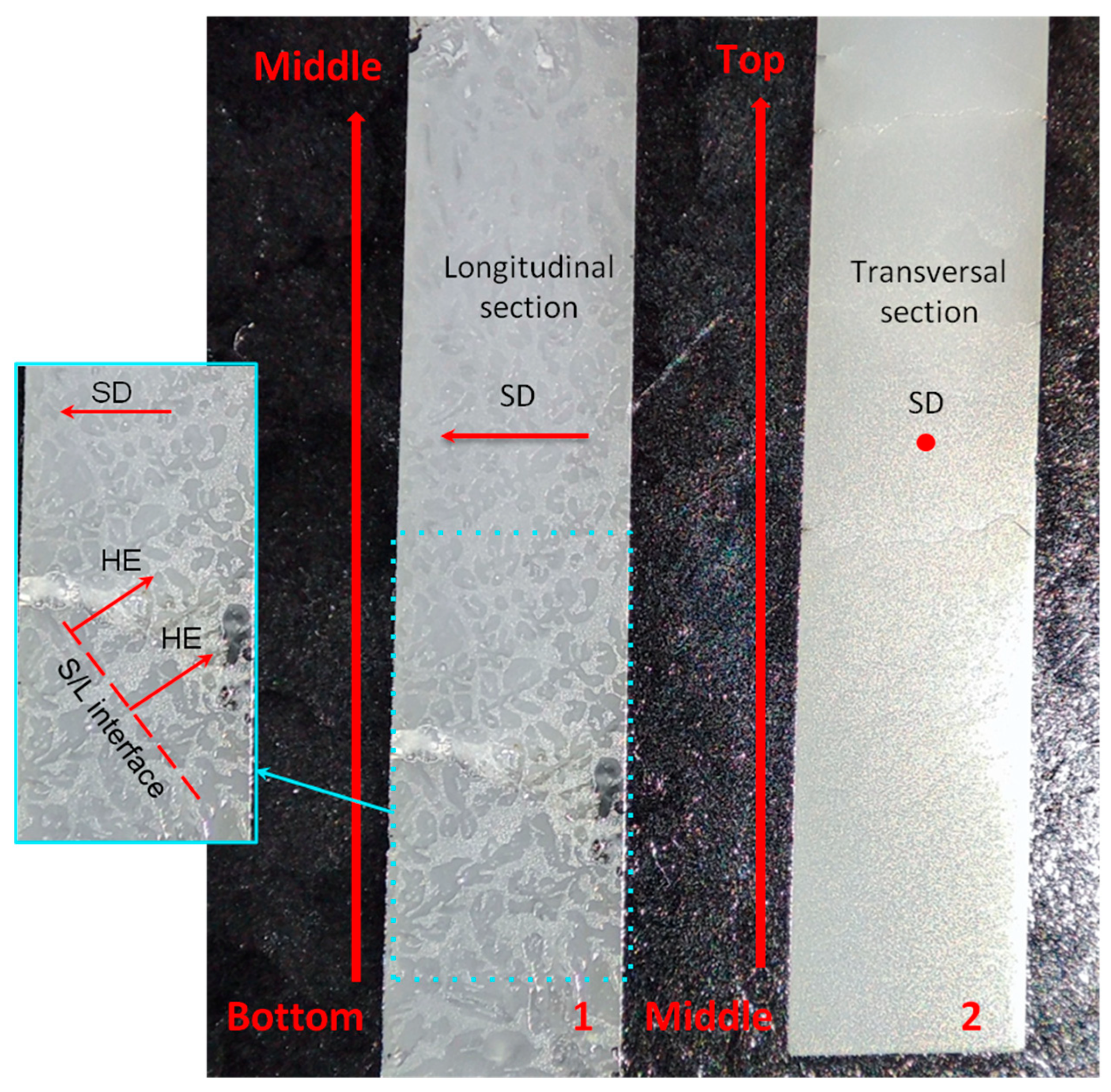
The solidified Al2O3/YAG eutectic ceramic ingot No. 1 is shown in Figure 1, along with a specimen measuring 50 × 50 × 35 mm that was cut from the ingot part corresponding to the completion of the initial transition stage of solidification. The X-Y-Z axes represent the orientation of the specimen in Figure 2, with Z denoting the solidification direction (SD). Neglecting fine structure details in the central region of the specimen, there is a two-layer structure along Z. The lower layer is translucent, and the upper one appears milky-colored. In order to examine the specimen’s texture using the EBSD method, we cut two samples in accordance with the Figure 2 scheme. The samples with a size of 3.43 × 20.15 mm, shown in Figure 3, were fixed in the epoxy resin (black color) and passed the complete processing before the EBSD measurement. Longitudinal and transversal cross-sections from the lower and upper layers of the specimen are presented by samples (1) and (2), respectively. The polished surface of the sample (1) displays the characteristic morphology of the competitive growth. The sample (2) is more homogeneous and less transparent.
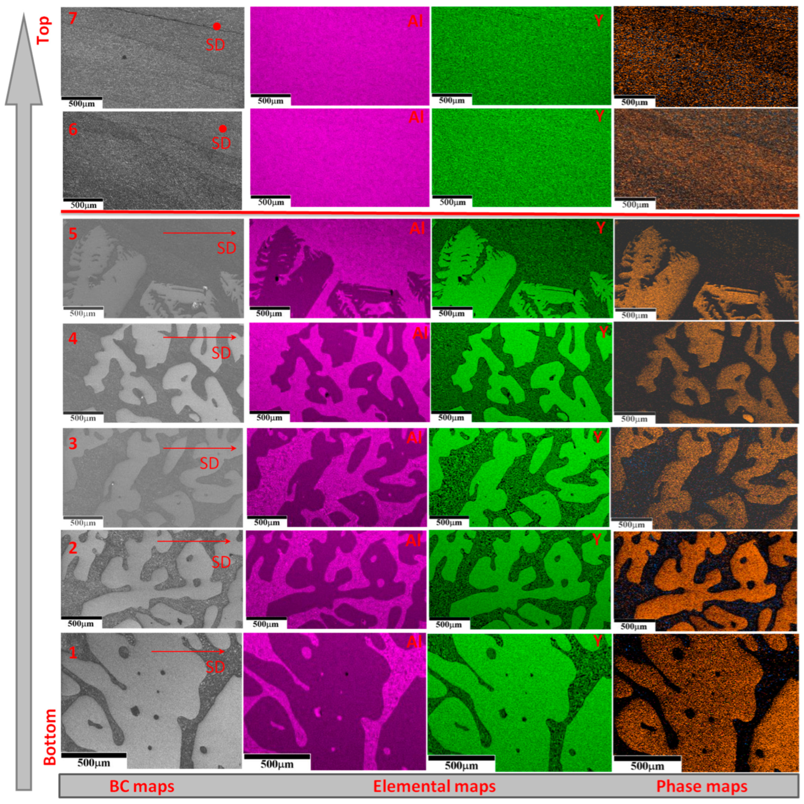
In an orderly manner from the bottom to the top of the specimen, Figure 4 presents the results of the EBSD analysis in terms of BC maps, elemental maps, and phase maps. Patterns 1–5 are related to Sample 1, revealing the presence of a dendrite-like YAG primary phase in the eutectic-type microstructure. In the bottom-to-top direction, the volume of the YAG primary phase decreases, and the dendrites acquire a more faceted shape. The authors of publication [27] demonstrated the impact of the Al2O3 and Y2O3 ratio in the composition range of 28.5–20.5 mol% Y2O3 on the content and shape of the YAG primary phase. The volume of the YAG phase decreases as the Y2O3 content decreases, and a transition to faceted forms of dendrites occurs at a composition of 22 mol% Y2O3. It seems that the change in the YAG dendrites’ content and the way they take on a faceted shape is connected to the melt’s composition changing at the S/L interface. Below in the text, we will provide a detailed analysis of this phenomenon.
The observed evolution of morphological forms (Figure 4, Patterns 1–5) corresponding to the competitive growth indicates the gradual decrease in the content of dendrites towards the boundary between the lower and upper layers of the ingot. This boundary can be observed in Pattern 5 of Figure 4, where the edge tips of the dendrites are visible, above which there is only a solidified eutectic structure corresponding to the coupled growth (Patterns 6 and 7, Figure 4). The microstructure of Sample 2, which corresponds to the upper layer, is homogeneous and represents the eutectic-type microstructure without the primary phase (Figure 3).
Three parameters control the coupled eutectic growth: the thermal gradient along the SD, the rate of solidification, and the melt composition (namely, its deviation from the eutectic one). The last two were initially set, and only a change in the thermal gradient can influence the solidification process. Therefore, to identify the reasons that caused the formation of the two-layer structure, it is necessary to consider the features of the HDS method. As mentioned above, the main feature of the HDS method is the largest value of RHT [39] through the upper surface (open to direct heat exchange) of the solidifying DSE ceramics. In accordance with the RHT mechanism for the materials with the internal scattering, the different solidification conditions in the upper and lower ingot layers occur. Backscattering of heat flows from the solidified upper part of ceramics leads to limited bottom heat transfer that provokes a decrease in the thermal gradient, forming a slope of the S/L interface (+φ), as shown in Figure 5.
According to the stability parameter proposed by Hunt and Jackson [40], aligned front growth (coupled growth) under the condition of a non-eutectic melt composition will take place at the high thermal gradient (or sufficient G/V value), and in the case of its reduction under a critical value, the transition to competitive growth will occur, characterized by the appearance of the primary phase dendrites.
The validity of the above analysis can be confirmed by considering the opposite case, with the constant gradient over the entire S/L interface. The publication [41] describes the appearance of the competitive growth at the beginning of the solidification process and further its transition into aligned front growth, which persists until the solidification end by the modified Bridgman method (molar ratio of Al2O3:Y2O3 = 79:21 mol%). The formed transition boundary between growth modes was located across SD, alternatively to the longitudinal one observed in our case. It is important to note that the melt compositions in both solidification processes were the same. Another confirmation of the proposed decrease in the thermal gradient is the similarity of the supposed and registered S/L interface slope. In Sample 1, the columnar YAG dendrites are visible; the direction of their growth coincides with the heat extraction (HE) direction indicated by the arrow in Figure 3. According to the condition of perpendicularity of the HE direction to the S/L interface, one can estimate its slope, which coincides with the hypothetical one (Figure 3 and Figure 5). This fact confirms that the thermal gradient is decreasing in the lower part of the S/L interface.
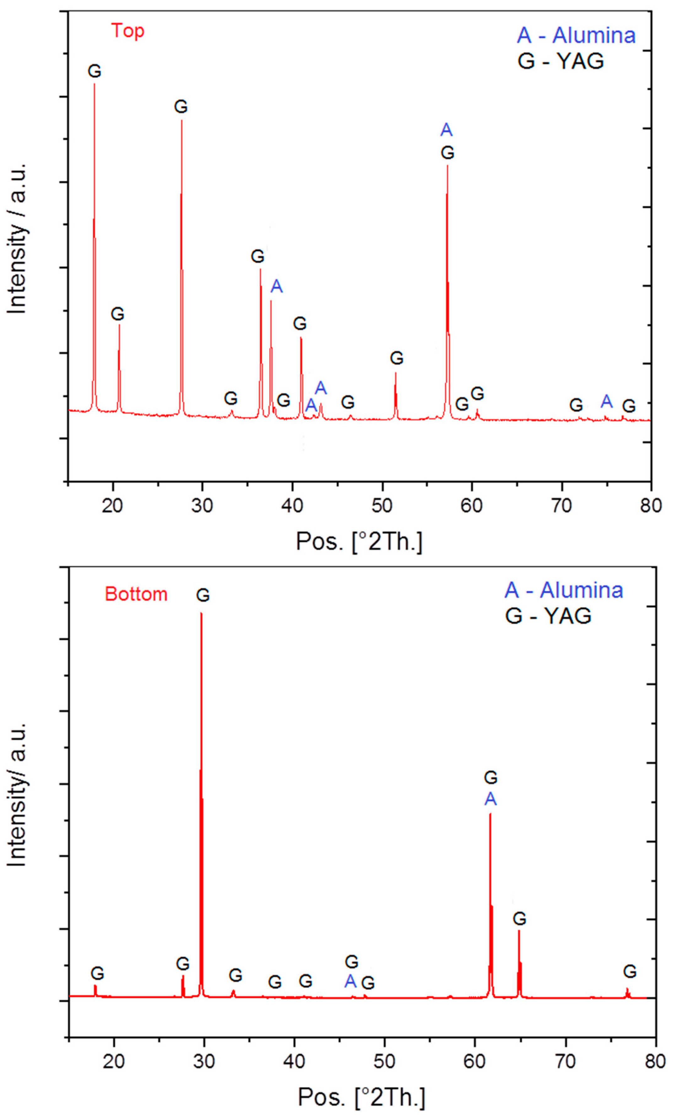
The change in solidification conditions causes a start of competitive growth, accompanied by segregation of the solute (Al2O3) depending on the volume fraction of the formed YAG dendrites. The higher level of the solute rejection at the lower S/L interface part evokes a higher level of convection. Initially, there is a single thermally driven cell characteristic of the HDS method, rotating clockwise (Figure 5). As time proceeds, the solute accumulates at the S/L interface, and a secondary solute-driven counterclockwise rotating cell develops (Figure 5). The effect of this convective pattern is to yield a significant level of solute redistribution at the interface [42]. Thus, the transfer of solute by convection shifts the composition of the melt to the eutectic one, providing better conditions for the coupled growth in the upper layer of the solidifying ingot. After the initial transient stage of solidification, equilibrium among the competitive growth in the lower part of the S/L interface, the solute transfer by thermosolutal convection from bottom to top, and the coupled growth mode in the upper part of this interface is established. The location of the ingot interlayer boundary parallel to the SD confirms the established equilibrium. The aligned front growth in the top layer of the solidified ingot is possible in the composition range of 20.5–18.5 mol% Y2O3 with appropriate G/V values [35], and mass is conserved by a change in the relative thickness of the lamellae [43]. The emergence of the solute concentration gradient in the melt is confirmed by the XRD analysis (Figure 6) and the above-discussed in the number and shape of dendrites in the bottom-to-top direction (Figure 4) indicating a noticeable increase in the Al2O3 content in the upper ingot layer.
Thus, thermosolutal solute convection and a significant temperature gradient difference in the upper and lower parts of the S/L interface support the simultaneous existence of two growth modes, leading to the formation of the observed boundary parallel to the SD. The extensive literature devoted to the solidification of eutectic compositions does not document the aforementioned phenomenon, thus affirming its originality and novelty.

3.2. Al2O3/YAG Eutectic Ceramic Ingot No. 2 (81.5 mol% Al2O3–18.5 mol% Y2O3 Composition)

According to the above analysis, the main reason for the competitive growth mode presence is the decrease in the thermal gradient in the lower part of the S/L interface. Furthermore, the coupled growth is unstable because of the hypoeutectic initial composition. In this case, the liquidus temperature exceeds the eutectic temperature, causing the excess primary phase to become more super-cooled and grow faster than the aligned front of YAG and Al2O3 lamellae. The Mullins–Sekerka S/L interface stability analysis [44] predicted such a situation, achieving coupled growth at a small G/V value for melts close to the eutectic composition. However, the greater the difference between the compositions of melt and eutectics, the larger G/V is required to avoid constitutional super-cooling and to achieve coupled growth conditions. Respectively, the composition for the ingot No. 2 of 18.5 mol% Y2O3 was selected, and the container pulling rate of 20 mm/h was set, while other process parameters remained unchanged.
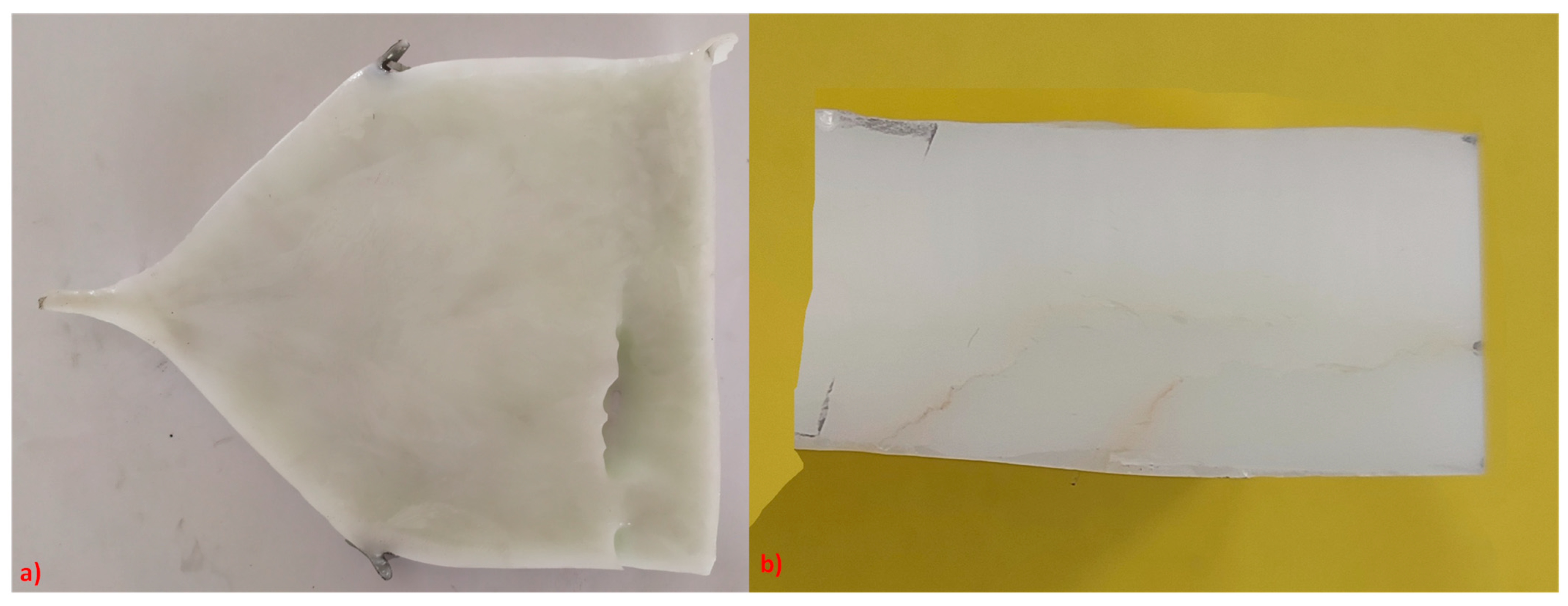
Figure 7 shows the photos of the resulting Al2O3/YAG eutectic ceramic ingot No. 2 and cut-out specimen, which are visually different from the previous one (Figure 1) by homogeneous structure in three main directions.
According to the scheme in Figure 2, we cut out samples 1’ and 2’, representing the upper and lower layers of the specimen, transversally to the SD. The EBSD analysis results presented in Figure 8 indicate the homogeneous eutectic-type microstructure without grain boundaries. Sub-grain boundaries observed in the BC maps and phase maps are likely places where internal stress distorts the crystal lattice, reducing the amount of recognizable Kikuchi patterns.

3.3. Characterization of Crystallographic Texture and Microstructure of Al2O3/YAG Eutectic Ceramics No. 1 and No. 2

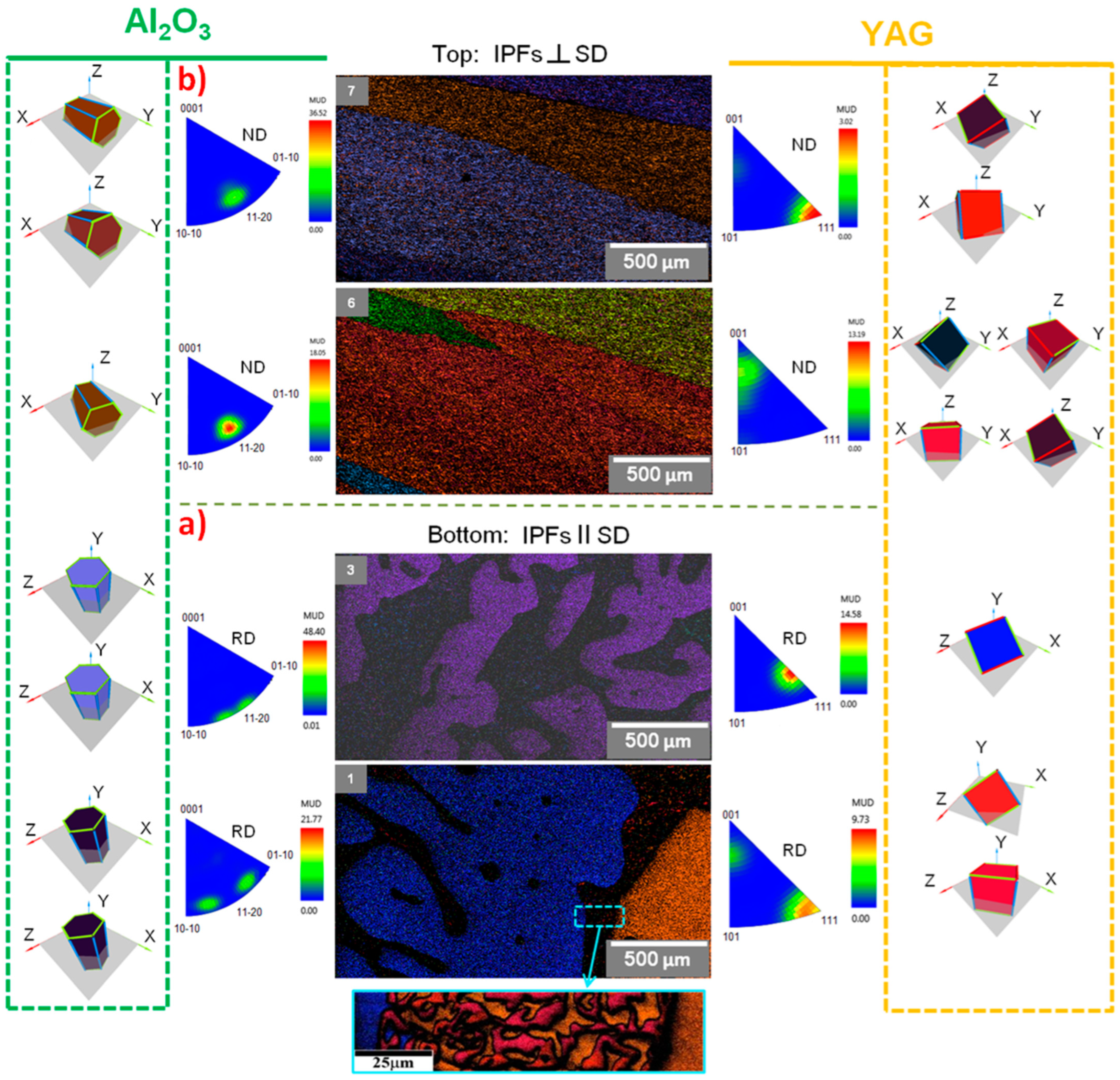
Figure 9 presents the results of the crystallographic texture investigation of DSE ceramics No. 1 using the EBSD analysis. Because dendrites are complex three-dimensional structures, the plane-section micrograph (Figure 9, Pattern 3) depicts branches of one dendrite with an orientation near 〈111〉 along the SD.
The YAG lamella orientation of the eutectic-type structure between the dendrites (Figure 9, Pattern 1) coincides with the orientation of the neighboring YAG dendrite (insert in Figure 9a), and Al2O3 IPFs poles deviate slightly from 〈10 1 ¯ 0〉, moving closer to the 〈11 2 ¯ 0〉 position (Figure 9b). The visible grain boundaries, resulting from different orientations of the YAG phase, are clearly visible in the upper layer of the eutectic structure without dendrites (Figure 9b, Patterns 6 and 7). As presented in Figure 9, there are a few YAG poles, one of which is close to 〈111〉 and the other is concentrated between the 〈101〉 and 〈001〉 crystallographic directions.
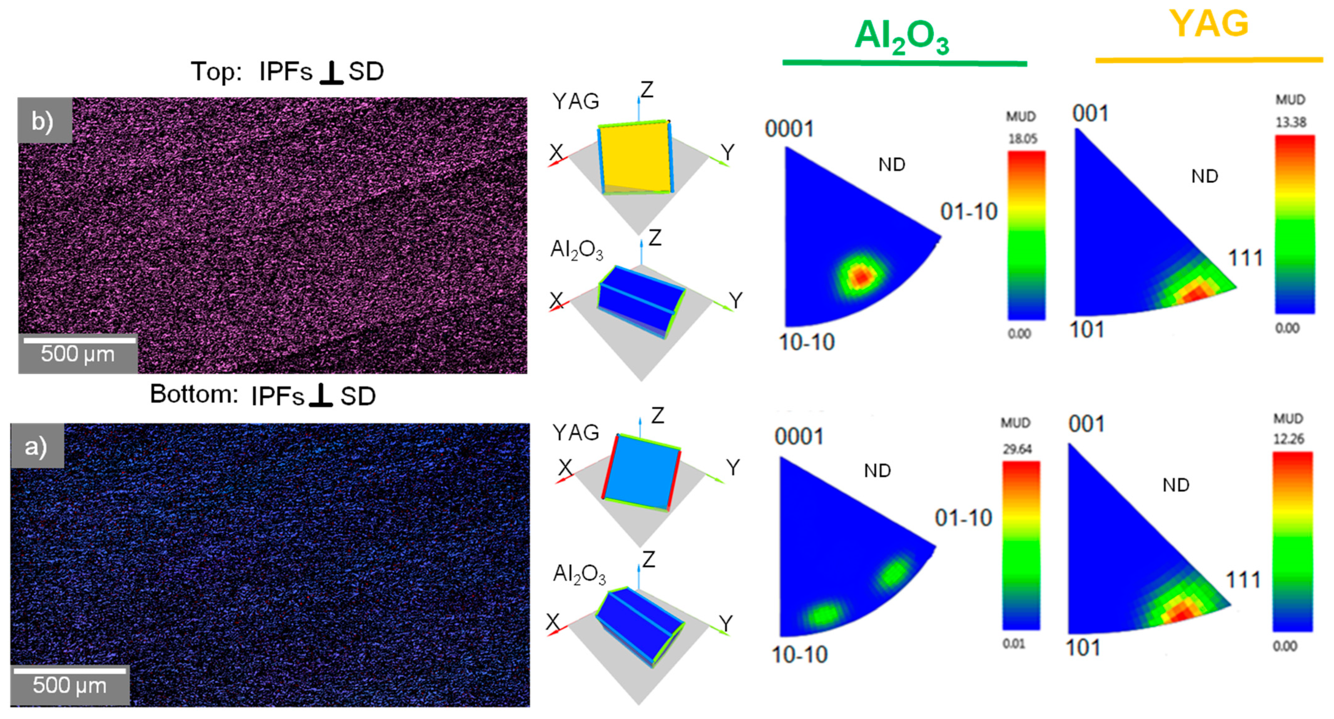
Figure 10 presents the crystallographic orientation maps, 3D crystal orientation images, and IPFs of the DSE ceramics No. 2.
Although the processing conditions of DSE ingots No. 1 and No. 2 are significantly different, in both cases, the crystallographic orientation of the Al2O3 phase is similar and undergoes a tendency to change from 〈10 1 ¯ 0〉 to 〈11 2 ¯ 0〉 in the bottom-to-top direction. A similar finding was discovered and described in publications [45,46], where the preferred growth orientation of Al2O3 changes from 〈10 1 ¯ 0〉 to 〈11 2 ¯ 0〉. According to the principle of minimizing the interfacial energy, the authors of the mentioned publications showed that the low anisotropy determines the equivalency of orientations 〈10 1 ¯ 0〉 and 〈11 2 ¯ 0〉 along the SD. These two orientations have a similar atomic arrangement and interfacial energy, which are obviously different from 〈0001〉. The YAG phase, on the other hand, does not seem to have a clear preferred orientation because it has an isotropic cubic structure, though samples 1’ and 2’ tend to have 〈111〉 oriented crystals.
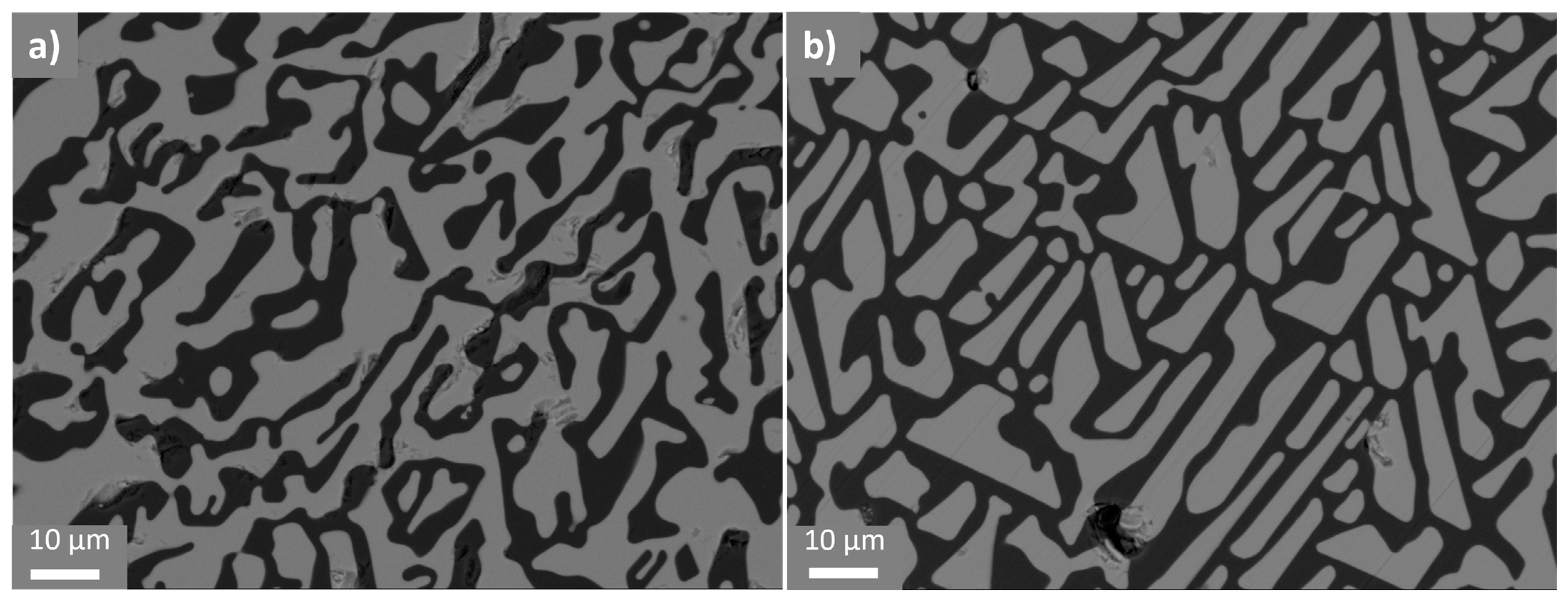
Figure 11a,b demonstrates the SEM micrographs of the transverse samples of the DSE ingots No. 1 and No. 2, respectively. The samples show the interpenetrating network of Al2O3 (black) and YAG (white) domains, shaped similar to “Chinese script” patterns.
The heterogeneity of the eutectic lamellae spacing of DSE ceramics No. 1 (Figure 11a) is associated with the unsteady crystallization conditions caused by the high solidification rate and the transfer of solute in the bottom-to-top direction. The eutectic lamella, through branching and converging, adapts to the S/L interface instabilities, generating the minimum super-cooling conditions for the eutectic coupled growth. In these conditions, the divergence and convergence of the lamellas become more intense. Because of this reason, the eutectic-type microstructure acquires dispersion in the domain sizes and a significantly weaker development of polyhedral shapes. Moreover, the high solidification rate leads to larger misorientation angles in the crystallographic texture [23]. The morphology of the sample (Figure 11b) of DSE ceramics No. 2 is homogeneous with sharp-angle and faceted shapes. There are no morphological changes across the SD, and the lamella spacing slightly fluctuates. The growth kinetics affect interfacial stability during coupled growth, decreasing interfacial energy by optimizing the crystallographic orientations. In order to bring the growth kinetics closer to the minimum under-cooling conditions, we changed the solidification rate and initial melt composition during the processing of DSE Ceramic 2. As a result, certain crystal orientations could not easily deviate, and faceted phases were acquired [47].

4. Conclusions

Two large-sized ceramic ingots of compositions corresponding to the extreme points of the eutectic range, i.e., hypereutectic (21 mol% Y2O3) and eutectic (18.5 mol% Y2O3) compositions, were obtained by the HDS method. The DSE ingot No. 1 had a two-layer structure with the expressed horizontal boundary separating the milky-colored upper layer with a eutectic-type structure from the translucent lower layer containing the YAG dendrites. Such structure feature indicates the simultaneous existence of two growth modes, which were supported by thermosolutal convection and a difference in the thermal gradient in the upper and lower parts of the S/L interface. Since this phenomenon was observed for the first time and has not been previously described in the literature, we tried to explain the causes of its emergence, taking into account the main mechanism of RHT and the feature of the HDS method.
The conditions for obtaining ceramics with a homogeneous eutectic structure were established. When obtaining the ingot No. 2, we used raw materials of the eutectic composition and carried out the processing with a solidification rate of 20 mm/h. The DSE ceramic ingot No. 2 had a homogeneous structure, and the studied samples were characterized by the eutectic-type microstructure without grain boundaries, which was caused by more ordered YAG orientation near 〈111〉 along the SD, which was not revealed for DSE ceramics No. 1. The preferred crystallographic orientation of Al2O3 in DSE ingot No. 1 is similar with the ingot No. 2, and close to 〈10 1 ¯ 0〉 and 〈11 2 ¯ 0〉 for the lower and upper parts, respectively. The morphology of the eutectic-type microstructure of both ingots is different. The presence of faceted forms and the more ordered structure of lamellas indicate the lower value of super-cooling during the solidification of DSE ceramic ingot No. 2. DSE ceramics can be promising materials for the design of next-generation aeroengines, gas turbine blades, and lining panels for turbine combustion chambers that function at inlet temperatures reaching 1700 °C.

Author Contributions

J.K.: conceptualization, project administration, funding acquisition, supervision; G.D.: conceptualization, data analysis, supervision, writing—review and editing; V.T.: methodology, specimens preparation, data treatment, writing—original draft; A.P.: project administration, data treatment, supervision; M.M.: XDR measurements and phase composition calculation by Rietveld method; P.Š.: SEM and EDSX investigations, data treatment; T.G.: project administration, funding acquisition; A.A.: data treatment; B.H.: data treatment; D.G.: supervision, conceptualization, writing—review and editing. All authors have read and agreed to the published version of the manuscript.

Funding

This research was funded by the Slovak Research and Development Agency under the contract No. APVV-19-0010 and by grant ITMS2014+ code 313011ASK8. This paper is a part of the dissemination activities of project FunGlass (Centre for Functional and Surface Functionalized Glass). This project has received funding from the European Union’s Horizon 2020 research and innovation program under grant agreement No. 739566 and also the Program for support of researchers threatened by the conflict in Ukraine—09I03-03-V01-00097.

Data Availability Statement

Data will be made available on request.

Conflicts of Interest

The authors declare no conflicts of interest.

References

  1. Parlier, M.; Valle, R.; Perrière, L.; Lartigue-Korinek, S.; Mazerolles, L. Potential of Directionally Solidified Eutectic Ceramics for High Temperature Applications. AerospaceLab 2011, 3, 1–13. [Google Scholar]
  2. Hirano, K. Application of eutectic composites to gas turbine system and fundamental fracture properties up to 1700 °C. J. Eur. Ceram. Soc. 2005, 25, 1191–1199. [Google Scholar] [CrossRef]
  3. Waku, Y.; Ohtsubo, H.; Nakagawa, N.; Kohtoku, Y. Sapphire Matrix Composites Reinforced with Single Crystal YAG Phases. J. Mater. Sci. 1996, 31, 4663–4670. [Google Scholar] [CrossRef]
  4. Waku, Y.; Nakagawa, N.; Ohtsubo, H.; Mitani, A.; Shimizu, K. Fracture and Deformation Behavior of Melt Growth Composites at very High Temperatures. J. Mater. Sci. 2001, 36, 1585–1594. [Google Scholar] [CrossRef]
  5. Stubican, V.S.; Bradt, R.C. Eutectic Solidification in Ceramic Systems. Ann. Rev. Mater. Sci. 1981, 11, 267–297. [Google Scholar] [CrossRef]
  6. Flemings, M.C. Solidification Processing. Metall. Trans. 1974, 5, 2121–2134. [Google Scholar] [CrossRef]
  7. Kurz, W.; Fisher, D.J. Dendrite growth in eutectic alloys. Int. Met. Rev. 1979, 24, 177–204. [Google Scholar] [CrossRef]
  8. Burden, M.H.; Hunt, J.D. The extent of the eutectic range. J. Cryst. Growth. 1974, 22, 328–330. [Google Scholar] [CrossRef]
  9. Viechnicki, D.; Schmid, F. Eutectic Solidification in the System Al2O3/Y3Al5O12. J. Mater. Sci. 1969, 4, 84–88. [Google Scholar] [CrossRef]
  10. Epelbaum, B.M.; Yoshikawa, A.; Shimamura, K.; Fukuda, T.; Suzuki, K.; Waku, Y. Microstructure of Al2O3/Y3Al5O12 eutectic fibers grown by μ-PD method. J. Cryst. Growth. 1999, 198–199, 471–475. [Google Scholar] [CrossRef]
  11. Yoshikawa, A.; Hasegawa, K.; Fukuda, T.; Suzuki, K.; Waku, Y. Growth and diameter control of Al2O3/Y3Al5O12 eutectic fiber by micro-pulling-down method and its high temperature strength and thermal stability. Jpn. J. Appl. Phys. 1999, 20, 275–282. [Google Scholar]
  12. Waku, Y.; Nakagawa, N.; Wakamoto, T.; Ohtsubo, H.; Shimizu, K.; Waku, Y. High-temperature strength and thermal stbility of a unidirectionally solidified Al2O3/YAG eutectic composite. J. Mater. Sci. 1998, 33, 1217–1225. [Google Scholar] [CrossRef]
  13. Parthasarathy, T.A.; Mah, T.; Matson, L.E. Processing, structure and properties of Alumina-YAG eutectic composites. J. Ceram. Process. Res. 2004, 5, 380–390. [Google Scholar]
  14. Liu, Y.; Su, H.; Tan, X.; Shen, Z.; Li, X.; Jiang, H.; Zhao, D.; Guo, Y.; Zhang, Z.; Guo, M. Stability of crystallographic texture and mechanical anisotropy toward Al2O3/YAG eutectic ceramic composite using single crystalline seeds. Compos. B Eng. 2024, 274, 111263. [Google Scholar] [CrossRef]
  15. Wang, X.; Zhang, W.; Xian, Q.; Shen, J.; Zhang, G.; Wang, D.; Wang, J.; Lou, L.; Zhang, J. Preparation and microstructure of large-sized directionally solidified Al2O3/Y3Al5O12 eutectics with the seeding technique. J. Eur. Ceram Soc. 2018, 38, 5625–5631. [Google Scholar] [CrossRef]
  16. Wang, X.; Tian, Z.; Zhang, W.; Zhong, Y.; Xian, Q.; Zhang, J.; Wang, J. Mechanical properties of directionally solidified Al2O3/Y3Al5O12 eutectic ceramic prepared by optical floating zone technique. J. Eur. Ceram. Soc. 2018, 38, 3610–3617. [Google Scholar] [CrossRef]
  17. Sai, Q.; Zhao, Z.; Xia, C.; Xu, X.; Wu, F.; Di, J.; Wang, L. Ce-doped Al2O3−YAG eutectic and its application for white LEDs. Opt. Mater. 2013, 35, 2155–2159. [Google Scholar] [CrossRef]
  18. Waku, Y.; Nakagawa, N.; Wakamoto, T.; Ohtsubo, H.; Shimizu, K.; Kohtoku, Y. A ductile ceramic eutectic composite with high strength at 1873 K. Nature 1997, 389, 49–52. [Google Scholar] [CrossRef]
  19. Oliete, P.B.; Peña, J.I.; Larrea, A.; Orera, V.M.; LLorca, J.; Pastor, J.Y.; Martín, A.; Segurado, J. Ultra-High-Strength Nanofibrillar Al2O3–YAG–YSZ Eutectics. Adv. Mater. 2007, 19, 2313–2318. [Google Scholar] [CrossRef]
  20. Borodin, V.A.; Reznikov, A.G.; Starostin, M.Y.; Steriopolo, T.A.; Tatarchenko, V.A.; Chernyshova, L.I.; Yalovets, T.N. Growth of Al2O3−ZrO2(Y2O3) eutectic composite by Stepanov technique. J. Cryst. Growth. 1987, 82, 177–181. [Google Scholar] [CrossRef]
  21. Su, H.; Zhang, J.; Ma, W.; Wei, K.; Liu, L.; Fu, H.; Feng, S.-P.; Soh, A.K. In situ fabrication of highly-dense Al2O3/YAG nanoeutectic composite ceramics by a modified laser surface processing. J. Eur. Ceram. Soc. 2014, 34, 739–744. [Google Scholar] [CrossRef]
  22. Lee, J.H.; Yoshikawa, A.; Fukuda, T. Growth of MgAl2O4/MgO eutectic crystals by the micro-pulling-down method and its characterization. J. Eur. Ceram. Soc. 2005, 25, 1351–1354. [Google Scholar] [CrossRef]
  23. Liu, Y.; Su, H.; Shen, Z.; Zhao, D.; Guo, Y.; Li, S.; Guo, M.; Liu, L.; Fu, H. Effect of seed orientations on crystallographic texture control in faceted Al2O3/YAG eutectic ceramic during directional solidification. J. Mater. Sci. Technol. 2023, 146, 86–101. [Google Scholar] [CrossRef]
  24. Murayama, Y.; Hanada, S.; Waku, Y. Microstructure and High-Temperature Strength of Directionally Solidified Al2O3/YAG Eutectic Composite. Mater. Trans. 2003, 44, 1690–1693. [Google Scholar] [CrossRef]
  25. Nie, Y.; Zhang, M.; Liu, Y.; Zhao, Y. Microstructure and mechanical properties of Al2O3/YAG eutectic ceramic grown by horizontal directional solidification method. J. Alloys Compd. 2016, 657, 184–191. [Google Scholar] [CrossRef]
  26. Nie, Y.; Han, J.; Liu, Y.; Zhang, M.; Zhang, J. Isotropy in large-size Al2O3/Y3Al5O12 eutectic ceramic grown by Horizontal Directional Solidification method. Mater. Sci. Eng. A 2017, 704, 207–211. [Google Scholar] [CrossRef]
  27. Bagdasarov, K.S.; Goryainov, L.A. Development of horizontally oriented crystallization of high-melting dielectric single crystals. J. Eng. Phys. Thermoph. 1998, 71, 248–253. [Google Scholar] [CrossRef]
  28. Akulenok, E.M.; Bagdasarov, K.S.; Danileiko, Y.K.; Lebedeva, T.P.; Manenkov, A.A. Diffusion of intrinsic defects in dielectric and semiconductor crystals with impurities. Cryst. Chem. 2002, 47, 918–924. [Google Scholar] [CrossRef]
  29. Bagdasarov, K.S. Fundamentals of high-temperature crystallization. Crystallogr. Rep. 2002, 47 (Suppl. S1), S27–S34. [Google Scholar] [CrossRef]
  30. Zhang, M.; Guo, H.; Han, J.; Zhang, H.; Xu, C. Distribution of Neodymium and properties of Nd:YAG crystal by horizontal directional solidification. J. Cryst. Growth 2012, 340, 130–134. [Google Scholar] [CrossRef]
  31. Chaika, M.; Ubizskii, S.; Kajan, J.; Gregor, T.; Gamazyan, G.; Marciniak, L. On the nature of CT luminescence in Yb3+:YAG single crystal under low photon energy. Opt. Mater. 2022, 130, 112548. [Google Scholar] [CrossRef]
  32. Palkech, J.; Kajan, J.; Malyukov, S.; Mikita, M.; Medvecky, S. Numerical simulation of heat transfer in a furnace heating unit for Horizontal Direct Crystallization of sapphire single-crystal. Am. J. Energy Eng. 2017, 4, 78–83. [Google Scholar]
  33. Medvecky, S.; Mikita, M.; Hoc, M.; Kajan, J. TRIZ and HDC sapphire growth process. J. Appl. Eng. Sci. 2017, 15, 9–14. [Google Scholar] [CrossRef]
  34. Yuferev, V.S.; Vasil’ev, M.G. Heat transfer in shaped thin-walled semi-transparent crystals pulled from the melt. J. Cryst. Growth 1987, 82, 31–38. [Google Scholar] [CrossRef]
  35. Mizutani, Y.; Yasuda, H.; Ohnaka, I.; Maeda, N.; Waku, Y. Coupled growth of unidirectionally solidified Al2O3–YAG eutectic ceramics. J. Cryst. Growth. 2002, 244, 384–392. [Google Scholar] [CrossRef]
  36. Mizutani, Y.; Yasuda, H.; Ohnaka, I.; Waku, Y. Phase selection of the Al2O3-Y2O3 system controlled by nucleation. Mater. Trans. 2001, 42, 238–244. [Google Scholar] [CrossRef]
  37. Yasuda, H.; Ohnaka, I.; Mizutani, Y.; Waku, Y. Selection of eutectic systems in Al2O3–Y2O3 ceramics. Sci. Tech. Adv. Mater. 2001, 2, 67–71. [Google Scholar] [CrossRef]
  38. Beausir, B.; Fundenberger, J.J. Analysis Tools for Electron and X-ray Diffraction, ATEX-Software, Université de Lorraine—Metz. 2017. Available online: http://www.atex-software.eu/ (accessed on 8 September 2024).
  39. Lukanina, M.A.; Hodosevitch, K.V.; Kalaev, V.V.; Semenov, V.B.; Sytin, V.N.; Raevsky, V.L. 3D numerical simulation of heat transfer during horizontal direct crystallization of corundum single crystals. J. Cryst. Growth 2006, 287, 330–334. [Google Scholar] [CrossRef]
  40. Burden, M.H.; Hunt, J.D. Cellular and dendritic growth. J. Cryst. Growth 1974, 22, 99–108. [Google Scholar] [CrossRef]
  41. Wang, X.; Zhang, N.; Zhong, Y.; Jiang, B.; Lou, L.; Zhang, J.; Wang, J. Microstructure evolution and crystallography of directionally solidified Al2O3/Y3Al5O12 eutectic ceramics prepared by the modified Bridgman method. J. Mater. Sci. Technol. 2019, 35, 1982–1988. [Google Scholar] [CrossRef]
  42. Simpson, J.E.; Garimella, S.V.; De Groh, H.C.; Abbaschian, R. Bridgman Crystal growth of an alloy with thermosolutal convection under microgravity conditions. Trans. ASME 2001, 123, 990–998. [Google Scholar] [CrossRef]
  43. Ashbrook, R.L. Directionally solidified Ceramic Eutectics. J. Am. Ceram. 1977, 60, 428–435. [Google Scholar] [CrossRef]
  44. Mullins, W.W.; Sekerka, R.F. Stability of a planar interface during solidification of a dilute binary alloy. J. Am. Ceram. Soc. 1964, 35, 444–451. [Google Scholar] [CrossRef]
  45. Viechnicki, D.; Schmid, F. Investigation of the eutectic point in the system Al2O3/Y3Al5O12. Mat. Res. Bull. 1969, 4, 129–135. [Google Scholar] [CrossRef]
  46. Liu, Y.; Su, H.; Shen, Z.; Li, X.; Jiang, H.; Di Zhao, N.; Guo, Y.; Zhang, Z.; Guo, M. Insight into the complex coupled growth behavior of Al2O3/YAG eutectic ceramic based on the evolutions of microstructure and crystallographic texture. J. Eur. Ceram. Soc. 2023, 43, 4482–4497. [Google Scholar] [CrossRef]
  47. Wang, X.; Wang, J.; Sun, L.; Zhang, H.; Wang, L.; Lou, L.; Zhang, J. Microstructure evolution of Al2O3/Y3Al5O12 eutectic crystal during directional solidification. Scr. Mater. 2015, 108, 31–34. [Google Scholar] [CrossRef]
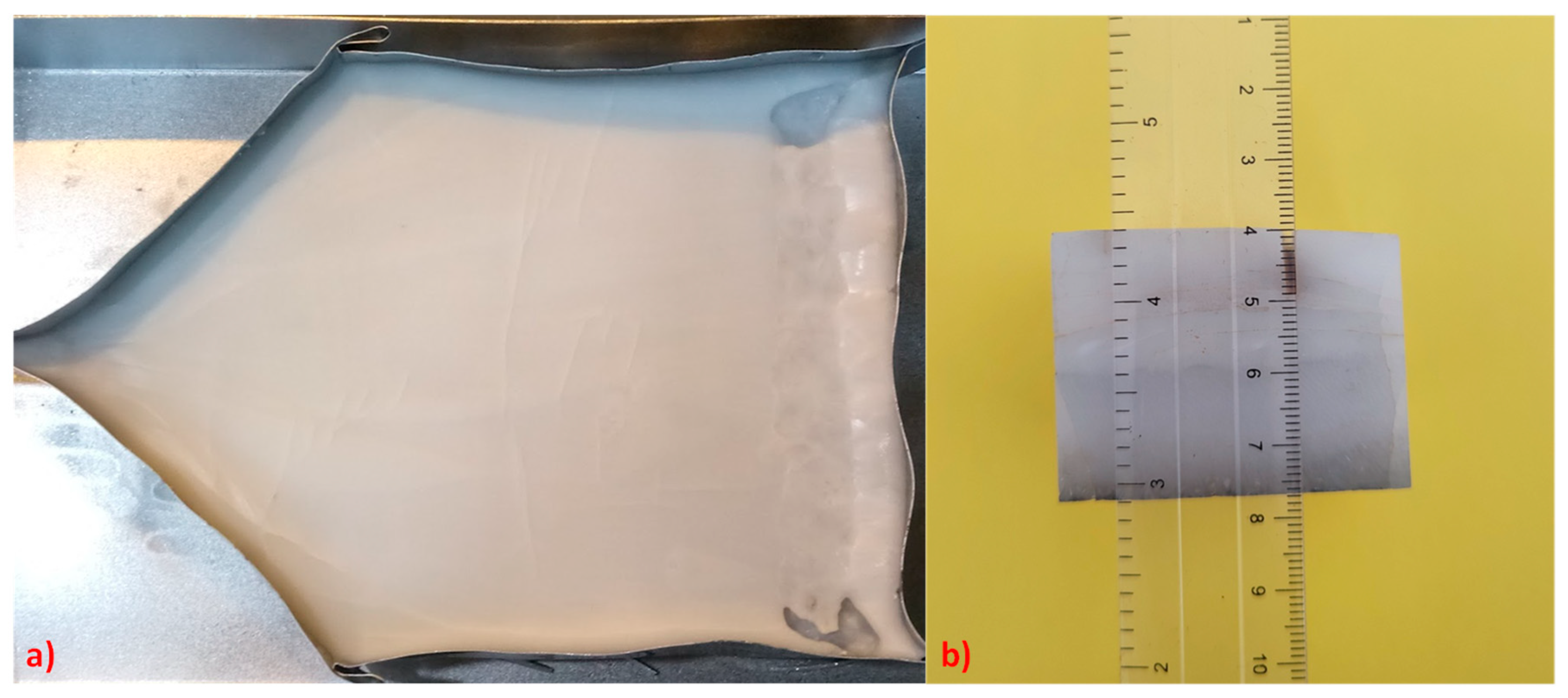
Figure 1. Digital photos of DSE ceramic ingot No. 1 (a) and the studied specimen (b).
Crystals 14 00858 g001
Figure 2. The scheme of the specimen and sample arrangement for the two DSE ceramic ingots. Samples 1, 2, and 1’, 2’ refer to the ingots No. 1 and No. 2, respectively.
Crystals 14 00858 g002
Figure 3. The samples prepared for EBSD analysis were cut out from the lower layer (1) and upper one (2) of the DSE ceramic ingot No. 1; SD—solidification direction, S/L—interface slope, HE—heat extraction.
Crystals 14 00858 g003
Figure 4. EBSD analysis results of DSE ceramic ingot No. 1: BC-maps (light-grey—YAG, dark-grey—eutectic-type structure), Elemental maps (Al—pink, Y—green), and Phase maps of the sample 1 (patterns 1–5) and sample 2 (patterns 6, 7) shown in Figure 3.
Crystals 14 00858 g004
Figure 5. Schematic view of HDS furnace: container with the raw material—1, the melt—2, solidified part—3, heaters—4, thermal insulation—5. Insert: the schematic image of the slope angle of the S/L interface.
Crystals 14 00858 g005
Figure 6. XRD patterns of (top) and (bottom) layers of DSE ceramic ingot No. 1.
Crystals 14 00858 g006
Figure 7. Digital photos of DSE ceramic ingot No. 2 (a) and the studied specimen (b).
Crystals 14 00858 g007
Figure 8. EBSD analysis results of DSE ceramic ingot No. 2: BC-maps (light-grey—YAG, dark-grey—eutectic-type structure), Elemental maps (Al—pink, Y—green), and Phase maps of the samples 1’ (a) and 2’ (b).
Crystals 14 00858 g008
Figure 9. Typical crystallographic orientation EBSD maps, IPFs, and the corresponding 3D crystal orientation images (YAG—cubes and Al2O3—hexagonal prisms) of Al2O3/YAG eutectics No. 1 (samples 1 (a) and 2 (b)). Insert: crystallographic orientation map of the eutectic-type structure between YAG dendrites (pattern 1) × 1000.
Crystals 14 00858 g009
Figure 10. Typical crystallographic orientation EBSD maps and the corresponding 3D crystal orientation Images (YAG—cubes and Al2O3—hexagonal prism), IPFs of Al2O3 and YAG of Al2O3/YAG eutectics No. 2 (Samples 1’ (a) and 2’ (b)).
Crystals 14 00858 g010
Figure 11. SEM images of the samples corresponding to the DSE ingots No. 1 (a) and No. 2 (b).
Crystals 14 00858 g011
Disclaimer/Publisher’s Note: The statements, opinions and data contained in all publications are solely those of the individual author(s) and contributor(s) and not of MDPI and/or the editor(s). MDPI and/or the editor(s) disclaim responsibility for any injury to people or property resulting from any ideas, methods, instructions or products referred to in the content.