Abstract
Double-wire arc welding involves simultaneously feeding two wires into a molten pool, improving the efficiency and flexibility of traditional welding techniques. However, the interactions between the two wires and the molten pools are complex, which increases the difficulties in process and composition control. This work focuses on the weld pool flow characteristics in double-wire TIG arc welding. A CFD model incorporating a liquid bridge transfer model was developed to simulate the fluid flow phenomenon. Results show that the bead-forming appearances and flow characteristics of double-wire arc welding show no significant differences from single-wire arc welding. Welding current and welding speed have significant effects on the weld bead dimensions, while only welding current has effects on the flow characteristics. Wire feed XOZ angles show no significant influences on weld bead forming appearances and molten pool flow characteristics. Wire feed XOY angles influence the symmetry of the weld bead and the fluid flow. In 5B71/7055 heterogeneous double-wire arc welding, achieving a uniform distribution of alloy elements is difficult due to the complex convection patterns within the molten pool.
1. Introduction
Arc welding is one of the fundamental material processing technologies in modern manufacturing. It plays important roles in different industries, varying from automotive to aerospace [1]. Throughout its storied history, numerous upgrades and adaptations have been made to this technique to achieve higher efficiency and better quality. Among these innovations, one particular technique has gained prominence due to advantages in both efficiency and flexibility: double-wire arc welding [2]. In this kind of welding technique, two wires are fed into a molten pool simultaneously. The wires can serve either as electrodes [3] or as feedstock [4], depending on the type of the heat source. Via feeding two wires, the deposition rates can be greatly enhanced, which promotes double-wire arc welding’s application in high-efficiency situations. Moreover, the composition of the two wires can be different. This unique feature made the composition of the weld bead controllable. By feeding heterogeneous wires with properly designed wire feed speeds, the weld bead of cross-over alloys, graded alloys, and even intermetallic compounds can be deposited, which is beneficial for weld bead property control, dissimilar materials welding, and additive manufacturing [5,6,7]. Cui et al. [4] fed two different wires in pulsed variable polarity plasma arc (VPPA) welding of AA2195 Al-Cu-Li to introduce Ti-Zr microalloying, and a 42 MPa increase in ultimate tensile strength was achieved. Hou et al. [8] fed Al-4.76Mg and Al-4.45Mg-0.70Sc-0.30Zr wires during cold metal transfer (CMT) welding of 7A52 aluminum alloys. The grains were refined by 87.7%. Wan et al. [9] fed ER2325 and ER5087 wires in the TIG welding of 2219 aluminum alloys. The yield strength of the joint was increased by 80 MPa. Feng et al. [10] applied 52M/308L double-wire welding in SA508/316L dissimilar joints. When the wire feed rate ratio was 75%: 25%, joints with high hardness and low residual stress could be obtained. Huang et al. [11] applied Ni/Ti double-wire welding to additive manufacturing of NiTi shape memory alloy. The deposited alloy exhibits a shape memory recovery rate of up to 88%.
However, the application of double-wire arc welding still faces challenges. With two feedstocks, the molten pool flow during double-wire welding differs from traditional welding. The relationship between processing conditions and forming characteristics becomes complex. The synchronization of the two wires requires a more intricate match of parameters. For the application where dissimilar wires are used, the transportation of alloy elements in the molten pool needs to be controlled to ensure the homogeneity of the weld bead. To break through these challenges, we must establish a systematic understanding of the basic flow behaviors during double-wire welding.
Since the physical investigation approach to the molten pool of arc welding is strongly influenced by the high temperature, intense light, and complex electromagnetic interferences from the arc plasma [12], computational fluid dynamic (CFD) simulation is an effective and widely accepted way to research the flow behaviors during arc welding [13]. Different physical fields can be visualized independently, which is beneficial for understanding the physical nature behind the complex welding phenomenon [14]. Hao et al. [15] simulated the dynamic weld pool behaviors in reserved gap tungsten inert gas (TIG) welding and clarified the internal relationships between forming appearances and the gap sizes. Lang et al. [16] proposed a coupling model to simulate the weld pool flow during VPPA vertical-up welding and explained the key factors that influence the stability of the keyhole. Xu et al. [17] investigated the fluid flow during microplasma arc welding and clarified the molten pool responses to pulse parameters. Han et al. [18,19] established a CFD model to simulate the flow behaviors in tandem narrow gap welding. They explained the relationship between processing parameters and the lack-of-fusion defects. Jia et al. [20] modeled the molten pool behavior in ultrasonic-assisted metal inert gas (MIG) welding. The effects of ultrasonic waves on the fluid flow were investigated. Lang et al. [21] studied the keyhole evolution in VPPA welding of medium-thickness aluminum alloys via CFD simulations. The relationship between temperature gradient and keyhole stability was established. Zhang et al. [22] modeled the molten pool flow in TIG-MIG hybrid welding and proposed the suppression mechanism of welding defects based on the results. Wang et al. [23] established a CFD model to investigate the keyhole dynamics in keyhole TIG welding and analyzed the influences of different driving forces on the keyhole evolution. Esmati et al. [24] established a model to simulate the chemical mixing phenomenon in dissimilar welding, and they clarified the transportation behaviors of Fe, Cr, and Ni.
This work delves deeper into the field of molten pool flow characteristics in double-wire TIG arc welding. A CFD model with a liquid bridge transfer model was established. The findings highlight the flow characteristics of the double-wire TIG arc welding, the molten pool responses to processing conditions, and the element transportation behaviors during heterogeneous double-wire TIG arc welding, offering new insights into the process optimization and visualization of the internal physical processes.
2. Numerical Model
The CFD model of double-wire arc welding was developed based on some preliminary assumptions: (1) The molten pool flow is laminar and in-compressible, (2) the electric arc can be simplified as thermal and mechanical interactions on the molten pool, (3) the liquid bridge transfer of the metal wire is ideal, and (4) the effects of metal vapor can be neglected. With these assumptions, the fluid flow in the molten pool can be described using the following control equations:
Mass conservation equation:
where ρ is the density of liquid metal, t is time, u, v, and w are the velocity components of the fluid in different directions, x, y, and z are the coordinates, and S is the source term.
Momentum conservation equations:
where p is the pressure, μ is the viscosity, Fex, Fey, and Fez are the source terms in different directions, and g is the gravitational acceleration.
Energy conservation equation:
where T is the temperature, k is the thermal conductivity, and Q is the source term.
VOF equation:
where F is the volume of fluid function.
The source term of the momentum conservation equation is the electromagnetic force and buoyancy force:
where μ0 is the vacuum permeability, σj is the current distribution parameter, r is the distance to the arc center, Lm is the equivalent thickness, and TL is the liquidus temperature.
The source term of the energy conservation equation is the energy input by the electric arc on the molten pool surface. Since the TIG welding is investigated in this work, an ellipse surface heat source is applied:
where η is the heat efficiency of the electric arc, U and I are the voltage and current of the arc, and σx, and σy are the shape parameters of the heat source.
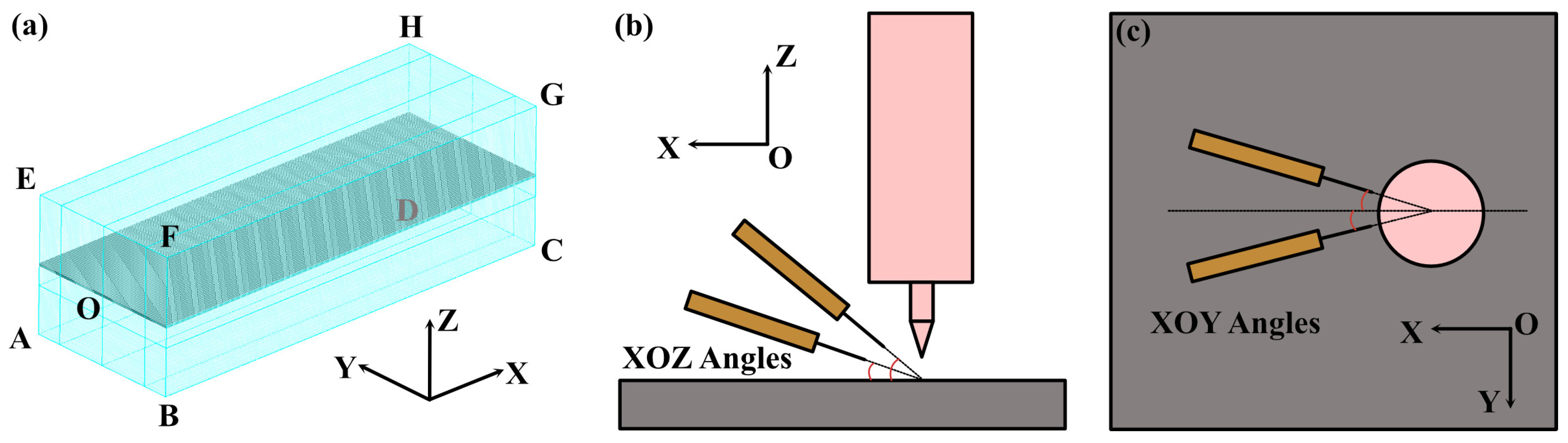
The above equations were solved using a finite difference solver. The meshed computational domain is shown in Figure 1a. We used full regular hexahedron cells with a size of 0.2 mm, which has been validated by mesh dependence tests. The number of cells is 1,996,800. The boundary conditions of the mesh block are listed in Table 1. The internal free surface boundary conditions include the surface tension and arc pressure. The surface tension pressure on the free surface is calculated by
where Pst is the surface tension pressure, γ is the surface tension, and κ is the local curvature of the free surface. The Marangoni stress is calculated by
where τma is the Marangoni stress, and s is the unit tangent. The surface tension is calculated by
where γ0 is the surface tension at the reference temperature, and Tref is the reference temperature.

Figure 1.
Simulation conditions: (a) mesh, (b) the definition of wire feed XOZ angles, and (c) the definition of wire feed XOY angles.

Table 1.
Boundary conditions of the mesh block.
The reliability of the model was validated in our former study [25]. And the same numerical model has been used for microstructural investigation, where the simulated results are in good agreement with the experimental results [26]. In this work, we applied different welding parameters and wire feeding conditions for comparison. The parameters for different cases are listed in Table 2. These process parameters were selected based on preliminary tests aimed at optimizing bead appearance and quality. The tests ensured that the chosen parameters would lead to optimal weld characteristics, allowing for a detailed evaluation of weld pool flow dynamics under beneficial conditions. For the convenience of describing the wire feed conditions quantitatively, we defined the wire feed XOZ angles and XOY angles, as illustrated in Figure 1b and Figure 1c, respectively. In Case 1, typical parameters were used to analyze the basic flow characteristics in double-wire welding. In Case 2, only a single wire was fed with doubled wire feed speed, which was used for comparing the differences between single and double-wire welding. In Case 3 and Case 4, the welding current is changed, which was used for investigating the influences of energy input. In Case 5 and Case 6, the welding velocity is accelerated, which was used for investigating the effects of welding velocity. In Case 7, Case 8, Case 9, and Case 10, the wire feed XOZ and XOY angles were changed to investigate the effects of wire feed conditions. Case 11, Case 12, and Case 13 are used to investigate the mass transfer during double-wire welding, where two wires with different compositions were fed, and during the calculation, another scalar transportation equations were included in the controlling equations:
where ϕk is the scalar concentration, Γk is the diffusion coefficient, and Sϕk is the source term of the scalar. The transport of alloying elements such as Sc is modeled using the scalar transport equation, which accounts for both convective and diffusive transport processes.
Table 2.
Simulation conditions for different cases.
3. Results and Discussion
3.1. The Development of Double-Wire Liquid Bridge Transfer Model
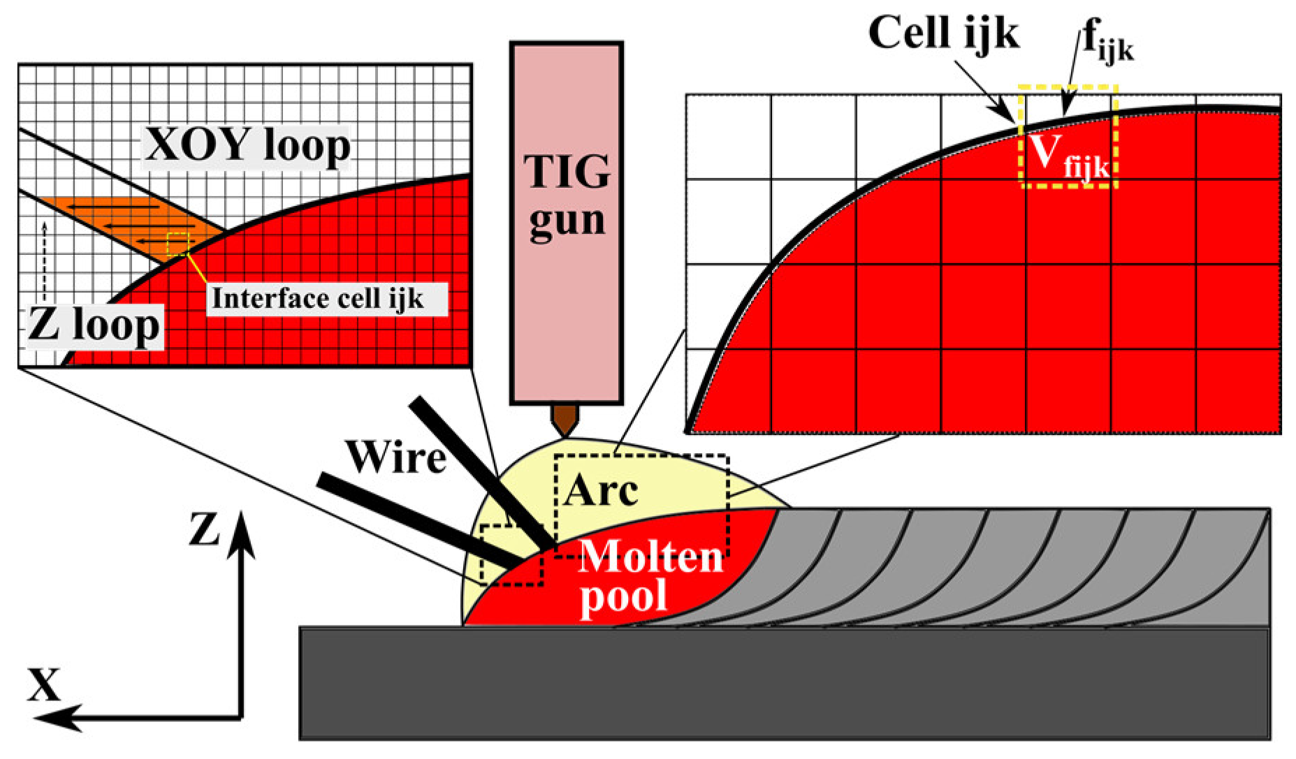
During an ideal stable double-wire TIG welding, wires are melted and transferred to the molten pool via a liquid bridge instead of forming droplets. To simulate the liquid bridge transfer phenomenon properly, we developed a model based on dynamic free surface tracking, as shown in Figure 2. In each step, before the source terms were added to the mass conservation equation, the free surface of the molten pool was tracked, and the interface cell ids ijk, cell volume Vijk, and fluid volume fraction fijk were stored. The liquid bridge was simplified as an ideal cylinder. The CFD solver is controlled to loop in the Z direction, i.e., traverse between cells on the XOY plane, move to the next z layer, and then repeat until all the cells are traversed. After the time step was determined by the solver, the filler volume Vstep in this step was renewed. Another temporary variable, Vt, was initiated to track the fluid volume that has been generated. During the loop process, cells that have been filled with fluid were skipped. For the interface cell ijk, we set the fluid volume fraction to 1 and set Vt to Vt + (1 − fijk)Vijk. For the empty cell ijk, we set the fluid volume fraction to 1 and set Vt to Vt + Vijk. When Vt equals Vstep, the filler metal generation for this step is stopped. In such a procedure, the filler metal can be generated exactly on the free surface of the molten pool, and the stable liquid bridge transfer can be established.

Figure 2.
The implementation model of double-wire liquid bridge transfer.
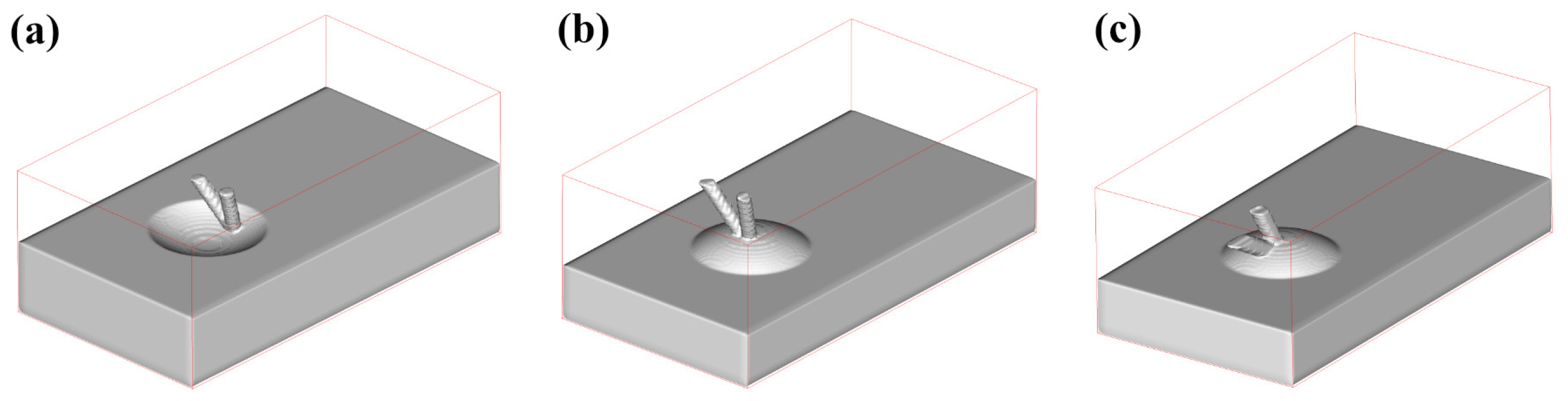
The reliability of the model was tested in different conditions, as shown in Figure 3. Figure 3a gives the wire feeding test on a concave-free surface, and two wires are fed with an XOY included angle of 60° and a YOZ included angle of 60°, while Figure 3b shows a test on a convex free surface with the same wire feeding angle. Figure 3c gives the test on a convex-free surface, and two wires were fed with an XOY included angle of 0° and a YOZ included angle of 30°. In all situations, the filler metal was properly generated on the free surfaces, which proves the validity of the model.
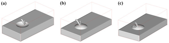
Figure 3.
Validation of the double-wire liquid bridge transfer: (a) on a concave surface, (b) and (c) on a convex surface.
3.2. Basic Weld Pool Flow Characteristics in Double-Wire Arc Welding
Then, the basic weld pool flow characteristics in double-wire arc welding were investigated based on the simulation results of Case 1. The weld bead appearances at different times are shown in Figure 4. The bead height near the starting point is relatively higher due to the strong heat dissipation effects of the base metal. Some undercuts were generated during the first 5 s. After that, as the temperature of the base metal becomes higher due to continuous weld heat input, the bead width and height become stable, and bead root fusion becomes better.
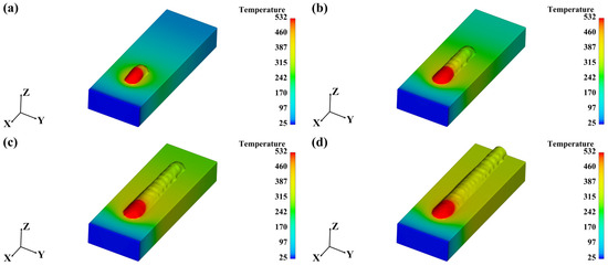
Figure 4.
The weld bead appearances at different times of double-wire welding: (a) 5.0 s, (b) 10.0 s, (c) 15.0 s, and (d) 20.0 s. (Temperature unit: °C.)
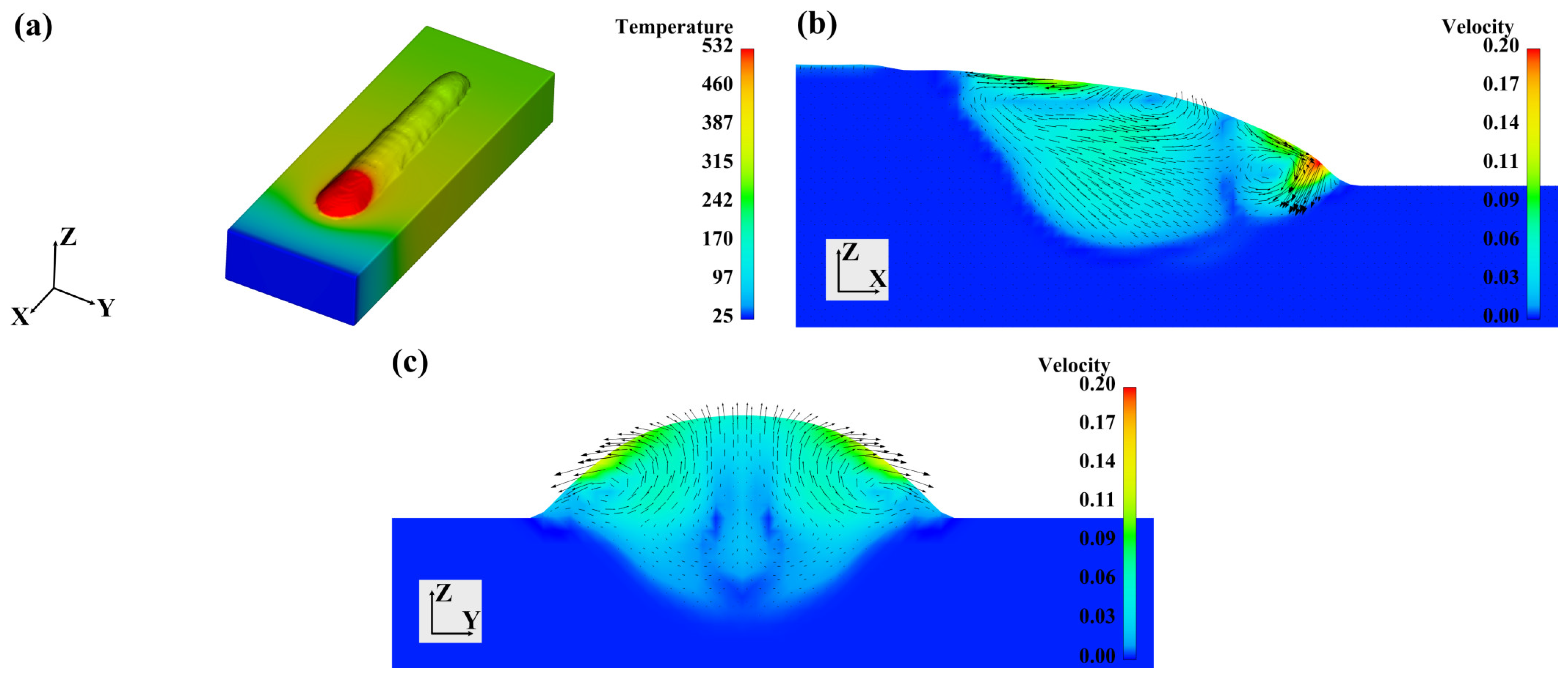
Figure 5a shows the molten pool flow on the free surface. The black arrows represent the velocity vectors. The melted metal presents a tendency to flow outward from the center to the boundary. The flow characteristics on the longitudinal section (XOZ plane) are shown in Figure 5b. The 2D section is extracted at the Y = 0 position, and the contour gives the velocity distribution. Most of the molten pools show a velocity below 0.12 m/s. The maximum velocity present near the transferring location of the lower wire exceeds 0.2 m/s. The upper wire did not introduce a significant downward flow tendency near the molten pool surface. Instead, the metal liquid flowed backward and formed an anticlockwise vortex. Between the upper wire and the lower wire transferring location, the metal liquid flows toward the frontward and forms a clockwise vortex. This flow manner is mainly driven by the Marangoni effects. The molten pool center has the highest temperature, with a positive surface tension temperature coefficient. The Marangoni force drives the metal liquid to flow toward the low-temperature region. Figure 5c shows the flow characteristics on the cross-section (YOZ plane). The 2D section is extracted at the X = 0 position. The melted metal flows outward from the molten pool center, forming a pair of symmetrical vortexes, which is also the result of the Marangoni effects.

Figure 5.
The molten pool flow characteristics during double-wire welding: (a) on the molten pool surface, (b) on the longitudinal section (xoz plane), and (c) on the cross-section (yoz plane). (Temperature unit: °C, velocity unit: m/s.)
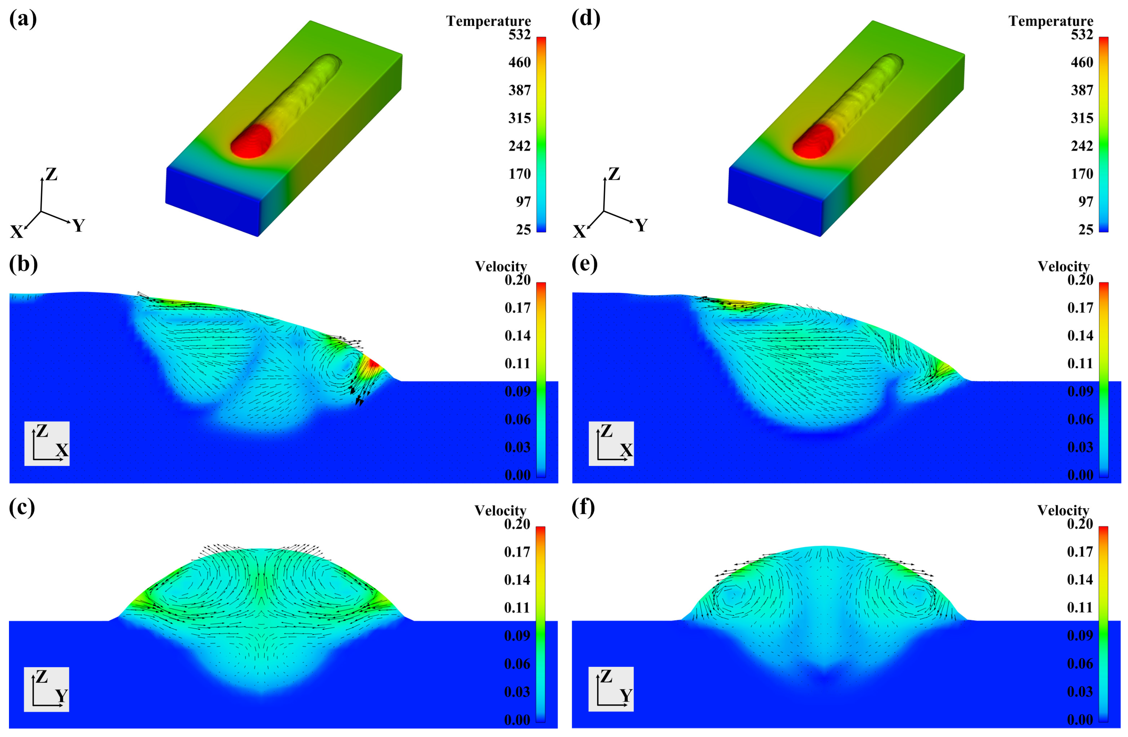
Single-wire welding with the same total wire feeding speed was simulated for comparison in Case 2. The results are given in Figure 6. As shown in Figure 6a, the forming appearance shows no significant difference from that of double-wire welding. In Figure 6b, since the single-wire feeding speed is doubled, the flow velocity near the transferring location is larger than that of double-wire welding. Figure 6c shows the flow characteristics of the cross-section. The basic flow manner of single-wire and double-wire welding. The melted liquid all shows an outward flow tendency from the molten pool center.

Figure 6.
The weld bead appearances and flow characteristics during single-wire welding: (a) weld bead appearances, weld pool flow characteristics on the (b) longitudinal section, and (c) cross-section. (Temperature unit: °C, velocity unit: m/s.)
3.3. The Effects of Processing Conditions on the Flow Characteristics
The effects of welding energy input on the flow characteristics of the molten pool were analyzed based on the simulation results of Case 1, Case 3, and Case 4. As shown in Figure 7a, with a lower energy input, the weld bead width decreases, and the weld bead height increases, while the forming angle increases. Since the molten pool temperature also decreases, the driven effects of Marangoni forces are weakened. So, the melted metal is mainly influenced by the liquid bridge transfer, presents a downward flow tendency with a large velocity between 0.11 and 0.14 m/s, and forms a clockwise vortex on the longitudinal section, as given in Figure 7b. On the cross-section (shown in Figure 7c), the fluid forms a par of inward vortex, presenting opposite directions compared with Case 1. When a larger energy input is used, as shown in Figure 7d, the weld bead width increases, the weld bead height decreases, and the forming angle decreases. Since the molten pool temperature increases again, the Marangoni force regains its primary driving role. The flow characteristics are similar to those in Case 1. On the longitudinal section, as shown in Figure 7e, the melted metal flows outward from the center to the boundary, while the liquid near the transferring location has a large velocity downward to the bottom of the molten pool. The melted metal forms an anticlockwise vortex at the tail of the molten pool while forming a clockwise vortex at the front of the molten pool. As shown in Figure 7f, on the cross-section, again, the melted metal flows outward from the molten pool center, forming a pair of symmetrical vortexes.
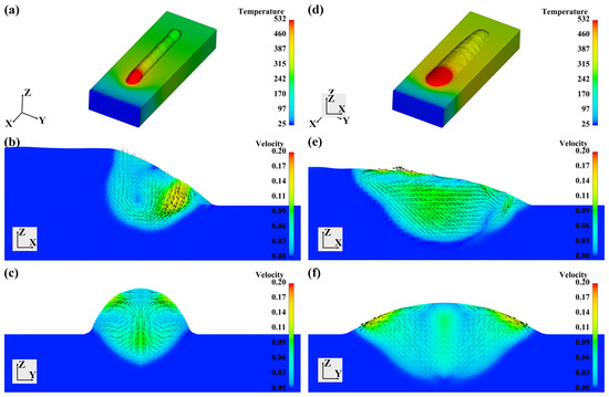
Figure 7.
The effects of welding energy input: weld bead appearances of (a) Case 3 and (d) Case 4; flow characteristics on the longitudinal sections of (b) Case 3 and (e) Case 4; flow characteristics on the cross-sections of (c) Case 3 and (f) Case 4. (Temperature unit: °C, velocity unit: m/s.)
The effects of welding speed on the flow characteristics of the molten pool were analyzed based on the simulation results of Case 1, Case 5, and Case 6. As shown by Figure 8a,d, with the welding speed increasing, the weld bead height decreases, while the weld bead width is almost not changed. Taking a closer look into the molten pool flow patterns, we found that the welding speed has very limited influences. On the longitudinal sections, as shown in Figure 8b,e, the melted metal flows outward from the molten pool center to the boundary, forming two opposite vortexes. On the cross-sections, as shown in Figure 8c,f, the metal liquid forms a pair of outward symmetrical vortexes. The differences in the velocity magnitudes are also small.
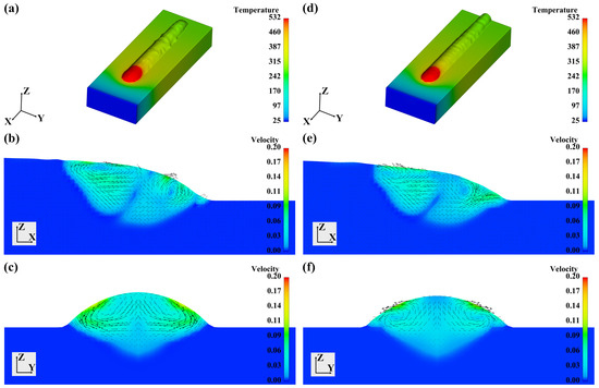
Figure 8.
The effects of welding speed: weld bead appearances of (a) Case 5 and (d) Case 6; flow characteristics on the longitudinal sections of (b) Case 5 and (e) Case 6; flow characteristics on the cross-sections of (c) Case 5 and (f) Case 6. (Temperature unit: °C, velocity unit: m/s.)
Then, we discuss the effects of wire feed angles. At first, different XOZ angles are compared based on the simulation results of Case 1, Case 7, and Case 8. We kept the angle of the lower wire at 30° unchanged and adjusted the angle of the upper wire to 45° and 75° in Case 7 and Case 8, respectively. As shown in Figure 9a,d, XOZ angles have very limited effects on the forming appearances. The weld bead width, height, and forming angles of Case 7 and Case 8 are similar to that of Case 1. On the longitudinal sections, as shown in Figure 9b,e, since the melted metal transferred from the upper wire flows along the free surface to the tail of the molten pool with the driven force of Marangoni effects, the XOZ angles also have limited influences on the flow characteristics. For the cross-sections, the outward vortexes are visible in Figure 9c,f. However, as the XOZ angle of the upper wire increases, the velocity magnitude on the cross-sections decreases. This is because when the XOZ angle of the upper wire is small, the velocity components on the free surface are larger, which leads to the intensification of transverse convection in the molten pool.

Figure 9.
The effects of wire feed angle (XOZ): weld bead appearances of (a) Case 7 and (d) Case 8; flow characteristics on the longitudinal sections of (b) Case 7 and (e) Case 8; flow characteristics on the cross-sections of (c) Case 7 and (f) Case 8. (Temperature unit: °C, velocity unit: m/s.)
Next, different XOY angles are compared based on the results of Case 1, Case 9, and Case 10. During the simulation, we set the XOZ angles of both wires at 30° and kept the XOY angle of one wire at 0° while changing the other wire to 30° (Case 9) and 60° (Case 10). Figure 10a,d give the forming appearances of Case 9 and Case 10, respectively. As the two wires are no longer symmetrical, the weld beads also become unsymmetrical. The weld bead surface is not uniform on the feeding side of the second wire. Compared with the symmetrical situation, weld bead height decreases while weld bead width increases slightly in Case 9 and Case 10. On the longitudinal section, as shown in Figure 10b,e, the flow characteristics are similar to those of Case 1. However, as the velocity components on the longitudinal plane reduce, the velocity of the downward flow at the front of the molten pool decreases significantly. Figure 10c,f give the flow characteristics of the cross-sections. The outward vortex flow manner is still visible. However, with the XOY, the angle of the wire increases due to the intensification of transverse velocity components. The vortex on the wire feeding side is intensified, and the profiles of the weld bead on the cross-section also become unsymmetrical.
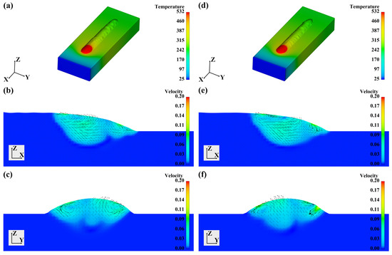
Figure 10.
The effects of wire feed angle (XOY): weld bead appearances of (a) Case 9 and (d) Case 10; flow characteristics on the longitudinal sections of (b) Case 9 and (e) Case 10; flow characteristics on the cross-sections of (c) Case 9 and (f) Case 10. (Temperature unit: °C, velocity unit: m/s.)
3.4. Mass Transfer in Heterogeneous Double-Wire Arc Welding
In double-wire arc welding, different wires can be fed at the same time to adjust the composition of the weld bead flexibly. In directed energy deposition based on double-wire arc welding, this technique can also be used for the in situ synthesis of cross-over alloys, intermetallics, and graded material. For these applications, the mass transfer behaviors are important, as they determine the uniformity of alloy elements in the weld bead. So, in this part, we made some exploration on the simulation of mass transfer in heterogeneous double-wire arc welding. Two different wires, 5B71 and 7055, are included, and their composition is given in Table 3. The Sc (Scandium) in 5B71-Al is an important grain refining element, so we mainly discuss the transportation of Sc during the double-wire welding. During the simulation, the influences of composition on the properties of the fluid are neglected. The transportation of alloy elements is calculated via the scalar transportation equation. Necessary transportation properties of the main alloy elements Zn, Mg, Cu, and Sc can be found in [27,28].
Table 3.
Chemical composition of wires (wt. %).
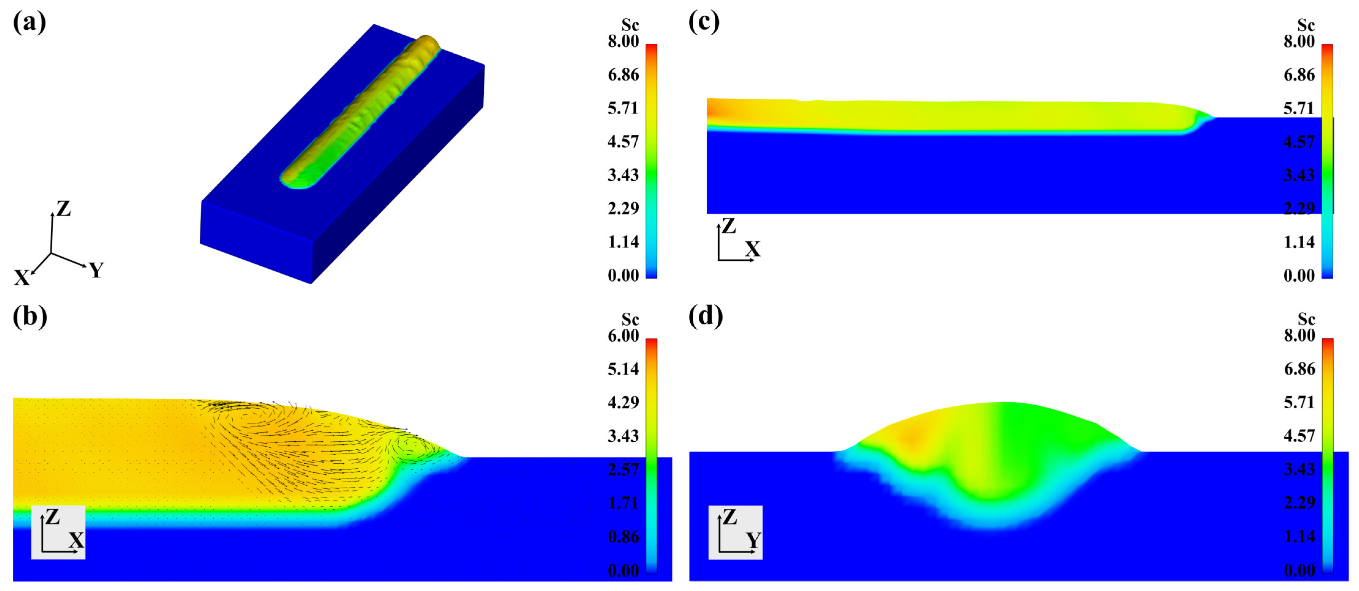
In Case 11, the 5B71 and 7055 wires were fed in the same XOZ plane with an included angle of 30°, where 5B71 was the upper wire, and 7055 was the lower wire. The distributions of Sc in different positions are shown in Figure 11. On the bead surface, as shown in Figure 11a, the aggregation of Sc can be found in the wire-transferring locations. And the Sc concentration is higher near the starting position of the weld bead. This is because the weld penetration is smaller near the starting location, and the attenuation effects from the base metal are weaker. In the molten pool, as shown in Figure 11b, the transportation of Sc is strongly influenced by the fluid flow. The concentration of Sc is high near the wire-transferring locations. With the front vortex flowing to the molten pool center, the distribution of Sc becomes much more uniform. The distribution of Sc on the longitudinal section and the cross-section is given in Figure 11c,d. The inhomogeneity of Sc distribution can be found in the X, Y, and Z directions.
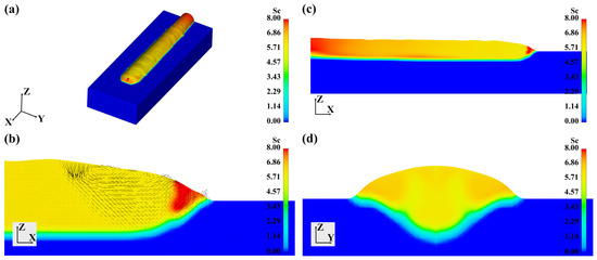
Figure 11.
The distribution of Sc in Case 11: (a) on the weld bead surface, (b) on the longitudinal section, (c) in the molten pool, and (d) on the cross-section. (Concentration unit: kg/m3).
Then, we investigated whether changing the wire feed angle can alleviate the inhomogeneity of alloy elements. In Case 12 and Case 13, the 5B71 and 7055 wires were fed symmetrically from different sides with an XOY included angle of 60° and 120°, respectively. The simulated distributions of Sc are displayed in Figure 12 and Figure 13. As shown in Figure 12, the longitudinal inhomogeneity was alleviated slightly. However, the transverse inhomogeneity increases. In Figure 13, the inhomogeneity is even more severe with a larger XOY angle. The results demonstrate that in heterogeneous double-wire arc welding, the inhomogeneous distribution of alloy elements is the key issue. The convection during welding itself makes it difficult to promote the uniform element distribution. Further processing approaches like forced oscillation and weld homogenization treatment should be considered.
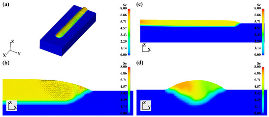
Figure 12.
The distribution of Sc in Case 12: (a) on the weld bead surface, (b) on the longitudinal section, (c) in the molten pool, and (d) on the cross-section. (Concentration unit: kg/m3).

Figure 13.
The distribution of Sc in Case 13: (a) on the weld bead surface, (b) on the longitudinal section, (c) in the molten pool, and (d) on the cross-section. (Concentration unit: kg/m3).
4. Conclusions
This study established a CFD model to investigate the weld pool flow characteristics in double-wire arc welding of aluminum alloys. This work provides new insights into the fluid dynamics of this advanced welding technique, which is helpful for process optimization and visualization of the internal physical processes. Our major findings are summarized as follows:
- (1)
- The bead-forming appearances and flow characteristics of double-wire arc welding show no significant differences from single-wire arc welding. The melted liquid, driven by the Marangoni effects, shows an outward tendency from the molten pool center to the boundary, forming opposite outward vortexes on both longitudinal sections and cross-sections.
- (2)
- Welding current and welding speed have significant effects on the weld bead dimensions. With a low welding current, the fluid flow in molten pools is mainly driven by the feedstock transfer. With a high welding current, the Marangoni forces take the initiative. Welding speed shows no significant influences on the metal liquid flow.
- (3)
- Wire feed XOZ angles show no significant influences on weld bead forming appearances and molten pool flow characteristics. Wire feed XOY angles influence the symmetry of the weld bead and the fluid flow.
- (4)
- In 5B71/7055 heterogeneous double-wire arc welding, achieving a uniform distribution of alloy elements is difficult due to the complex convection patterns within the molten pool. The alloy element concentration shows inhomogeneity in longitudinal, transverse, and height directions. Changing the wire feed XOY angles aggravates the inhomogeneity.
In summary, this study provides a deep understanding of the fundamental weld pool flow dynamics in double-wire arc welding, which can inform process optimization. Future work may focus on developing strategies to mitigate alloy element inhomogeneity and enhancing the process controllability of double-wire arc welding based on the established model.
Author Contributions
Investigation, B.D.; validation, Y.X. and Z.N.; writing—original draft preparation, B.D.; supervision, X.C.; project administration, S.L. All authors have read and agreed to the published version of the manuscript.
Funding
This research was funded by the National Key R&D Program of China, grant number 2023YFE0201500; the National Natural Science Foundation of China, grant numbers U21B2080, 52305351, and 52275324; the Heilongjiang Provincial Postdoctoral Science Foundation, grant number LBH-Z22128; and the China Postdoctoral Science Foundation, grant number 2023M730838.
Data Availability Statement
The original contributions presented in the study are included in the article; further inquiries can be directed to the corresponding author.
Conflicts of Interest
The authors declare no conflicts of interest.
References
- Jiang, F.; Peng, S.; Zhang, G.; Xu, B.; Cai, X.; Chen, S.; Zhang, P. Investigation of Arc Behavior and Welding Formation for a Novel Vector Gas Regulated Plasma Arc Welding. J. Manuf. Process. 2024, 119, 768–780. [Google Scholar] [CrossRef]
- Wang, L.; Gu, Y.; Quan, M.; Liu, A.; Wu, C.; Yang, X.; Liang, Z.; Wang, D.; Liu, Y.; Peng, Z.; et al. The Arc Stability and Droplet Transfer Characteristics of an Alternating Current Heterogeneous Twin-Wire Indirect Arc Welding. J. Mater. Process. Technol. 2024, 332, 118570. [Google Scholar] [CrossRef]
- Wu, K.; Zeng, Y.; Zhang, M.; Hong, X.; Xie, P. Effect of High-Frequency Phase Shift on Metal Transfer and Weld Formation in Aluminum Alloy Double-Wire DP-GMAW. J. Manuf. Process. 2022, 75, 301–319. [Google Scholar] [CrossRef]
- Cui, G.; Yang, C. Formation and Strengthening Mechanism of Equiaxial Cellular Grain Zone in AA2195-T8 Al–Cu–Li Alloy Twin-Wire P-VPPA Welded Joint with Ti–Zr Microalloying. Mater. Sci. Eng. A 2024, 896, 146278. [Google Scholar] [CrossRef]
- Xu, T.; Zhang, M.; Wang, J.; Lu, T.; Ma, S.; Liu, C. Research on High Efficiency Deposition Method of Titanium Alloy Based on Double-Hot-Wire Arc Additive Manufacturing and Heat Treatment. J. Manuf. Process. 2022, 79, 60–69. [Google Scholar] [CrossRef]
- Meng, Y.; Li, J.; Gao, M.; Chen, H. Preparation of Ni–Al Intermetallic Compounds by Plasma Arc Melting Deposition through Double-Wire Feeding. J. Mater. Res. Technol. 2023, 24, 6174–6186. [Google Scholar] [CrossRef]
- Kong, H.; Liu, Y.; Ren, H.; Li, F.; Kang, K.; Tao, Y.; Sun, Q. Surface Modification of Mild Steel via Heterogeneous Double-Wire Arc Directed Energy Deposition: Microstructure and Performance of Cladding Layer. Surf. Coat. Technol. 2024, 482, 130751. [Google Scholar] [CrossRef]
- Hou, X.; Zhao, L.; Ren, S.; Peng, Y.; Ma, C.; Tian, Z.; Qu, X. Effect of Sc and Zr Addition on Microstructure and Mechanical Properties of High Strength 7A52 Aluminum Alloy Welded Joints Fabricated by Double-Wire Gas Metal Arc Welding. Mater. Today Commun. 2024, 38, 108341. [Google Scholar] [CrossRef]
- Wan, Z.; Zhao, Y.; Zhang, S.; Zhao, T.; Li, Q.; Shan, J.; Wu, A. Novel Weld Composition to Improve Mechanical Properties of 2219-T8 Aluminum Alloy Joint Using Double-Wire TIG Welding. Mater. Charact. 2024, 209, 113764. [Google Scholar] [CrossRef]
- Feng, J.; Luo, C.; Liu, J.; Liu, H.; Zhang, Y.; Chen, X.; Jiang, M.; Tian, Y. Narrow Gap Multi-Pass Laser Welding with 52M/308L Double Wires Filler Addition for SA508/316L Dissimilar Metals. Int. J. Press. Vessel. Pip. 2024, 211, 105286. [Google Scholar] [CrossRef]
- Huang, Y.; Xin, D.; Chen, X. Microstructure and Properties of NiTi Shape Memory Alloy Fabricated by Double-Wire Plasma Arc Additive Manufacturing with a Nearly Equal Atomic Ratio. Mater. Lett. 2024, 354, 135406. [Google Scholar] [CrossRef]
- Wang, D.; Lu, H. Numerical Analysis of Internal Flow of Molten Pool in Pulsed Gas Tungsten Arc Welding Using a Fully Coupled Model with Free Surface. Int. J. Heat Mass Transf. 2021, 165, 120572. [Google Scholar] [CrossRef]
- Cai, C.; He, Y.; Xie, J.; Yu, J.; Xu, L.; Chen, Z.; Li, Z.; Wang, E.; Chen, H. Porosity Suppression Mechanism Analysis in Narrow-Gap Oscillating Laser-MIG Hybrid Welding of Aluminum Alloys Based on Keyhole Stability and Molten Pool Flow Behavior. J. Mater. Res. Technol. 2024, 32, 502–518. [Google Scholar] [CrossRef]
- Fan, D.; Wang, Y.; Zhang, C.; Huang, J.; Li, D. Numerical Analysis of Arc-Droplet-Pool Coupling Behavior in Magnetically Controlled High Current MIG Welding. J. Manuf. Process. 2024, 126, 402–412. [Google Scholar] [CrossRef]
- Hao, H.; Gao, J.; Huang, H. Numerical Simulation for Dynamic Behavior of Molten Pool in Tungsten Inert Gas Welding with Reserved Gap. J. Manuf. Process. 2020, 58, 11–18. [Google Scholar] [CrossRef]
- Lang, R.; Han, Y.; Bai, X.; Bao, X. Influence of the Metal Flow in the Keyhole Molten Pool on the Molten Pool Stability in Continuous Variable Polarity Plasma Arc Keyhole Vertical-up Welding. J. Manuf. Process. 2022, 76, 195–209. [Google Scholar] [CrossRef]
- Xu, L.; He, J.; Pan, X.; Ji, Y.; Wu, Q.; Jin, S. Numerical and Experimental Study on Oscillation Mechanism of Molten Pool during Pulsed Microplasma Arc Welding Ultrathin Sheets. Results Phys. 2022, 35, 105359. [Google Scholar] [CrossRef]
- Han, S.; Liu, G.; Tang, X.; Xu, L.; Cui, H.; Shao, C. Effect of Molten Pool Behaviors on Welding Defects in Tandem NG-GMAW Based on CFD Simulation. Int. J. Heat Mass Transf. 2022, 195, 123165. [Google Scholar] [CrossRef]
- Han, S.; Li, J.; Shao, C.; Cui, H.; Tang, X. Numerical Evaluation of Interwire Angle Influence on Molten Pool Fluid Dynamics and Weld Defects in Tandem NG-GMAW of 5083 Aluminum Alloy. J. Manuf. Process. 2024, 124, 1112–1123. [Google Scholar] [CrossRef]
- Jia, H.; Cao, L.; Fu, S.; Wen, H.; Ma, G. Numerical Simulation and Experiment for the Dynamic Behavior of Molten Pool in Ultrasonic-Assisted MIG Welding. Int. J. Heat Mass Transf. 2023, 215, 124469. [Google Scholar] [CrossRef]
- Lang, R.; Han, Y.; Bao, X.; Fan, J. Stability Mechanism of the Molten Pool in Variable Polarity Plasma Arc Welding of Medium Thickness Aluminum Alloy. J. Mater. Process. Technol. 2023, 321, 118127. [Google Scholar] [CrossRef]
- Zhang, Y.; Li, Y.; Zhang, Y.; Zong, R. Numerical Analysis of the Behavior of Molten Pool and the Suppression Mechanism of Undercut Defect in TIG-MIG Hybrid Welding. Int. J. Heat Mass Transf. 2024, 218, 124757. [Google Scholar] [CrossRef]
- Wang, X.; Zhang, J.; Tashiro, S.; Tanaka, M. Study of Molten Pool Dynamics in Keyhole TIG Welding by Numerical Modelling. J. Manuf. Process. 2024, 119, 827–841. [Google Scholar] [CrossRef]
- Esmati, P.; Flint, T.; Akyel, F.; Olschok, S.; Reisgen, U.; Cardiff, P.; Larrosa, N.O.; Grilli, N. Simulating Chemical Mixing and Molten Pool Shape in Dissimilar Welds Using Thermal Fluid Dynamics. Int. J. Heat Mass Transf. 2024, 226, 125449. [Google Scholar] [CrossRef]
- Cai, X.; Dong, B.; Lin, S.; Li, X.; Fan, C. Forming Characteristics and Mechanism of Variable Polarity TIG-Based Wire Arc Additive Manufacturing of Al-Mg-Zn-Cu Alloy. Int. J. Adv. Manuf. Technol. 2022, 123, 3007–3020. [Google Scholar] [CrossRef]
- Dong, B.; Cai, X.; Chen, F.; Lin, S.; Zong, Y.; Shan, D. Twinned Dendrites Growth in Wire Arc Directed Energy Deposition of Al-Zn-Mg-Cu Alloy. Mater. Des. 2023, 228, 111821. [Google Scholar] [CrossRef]
- Luo, H.; Liu, W.; Ma, Y.; Xiao, D.; Liang, C. Unraveling L12 Al3X (X=Ti, Zr, Hf) Nano-Precipitate Evolution in Aluminum Alloys via Multi-Scale Diffusion Simulation. J. Mater. Res. Technol. 2024, 30, 7104–7114. [Google Scholar] [CrossRef]
- Xu, D.; Li, Z.; Wang, G.; Li, X.; Lv, X.; Zhang, Y.; Fan, Y.; Xiong, B. Phase Transformation and Microstructure Evolution of an Ultra-High Strength Al-Zn-Mg-Cu Alloy during Homogenization. Mater. Charact. 2017, 131, 285–297. [Google Scholar] [CrossRef]


Disclaimer/Publisher’s Note: The statements, opinions and data contained in all publications are solely those of the individual author(s) and contributor(s) and not of MDPI and/or the editor(s). MDPI and/or the editor(s) disclaim responsibility for any injury to people or property resulting from any ideas, methods, instructions or products referred to in the content. |
© 2024 by the authors. Licensee MDPI, Basel, Switzerland. This article is an open access article distributed under the terms and conditions of the Creative Commons Attribution (CC BY) license (https://creativecommons.org/licenses/by/4.0/).