Article

The Melt–Crystal Interface in the Production of Monocrystalline Sapphire via Heat Exchanger Method—Numerical Simulation Aspects

1
Materials Center Leoben Forschung GmbH, Roseggerstraße 12, 8700 Leoben, Austria
2
FAMETEC GmbH, Ebner-Platz 1, 4060 Leonding, Austria
*
Author to whom correspondence should be addressed.
Crystals 2024, 14(12), 1036; https://doi.org/10.3390/cryst14121036
Submission received: 6 November 2024 / Revised: 21 November 2024 / Accepted: 25 November 2024 / Published: 28 November 2024
(This article belongs to the Special Issue Young Crystallographers Across Europe)

Abstract

:
In this work, selected numerical simulation aspects are analyzed in terms of their effect on predictions of the m-c interface. The fixed-grid enthalpy porosity phase change model, which is highly attractive in the field of modeling sapphire crystallization processes, is examined for its sensitivity to the mushy zone parameter as well as the grid resolution. A further focus is set to the simulation of thermal transport including internal radiation in the crystal and the melt via the finite volume method. Depending on the purpose of the investigation, different requirements on the angular resolutions are relevant. While most of the m-c interface as well as the temperature distribution remain practically unchanged at reasonable resolutions, a high sensitivity of the m-c interface in the near-wall region is demonstrated. This sensitivity is also observed in terms of radiative transport and, hence, the total heat transfer.

1. Introduction

In the past decades, the demand for high-quality monocrystalline sapphire has been constantly increasing. A strong driving factor in this development is the rising market for µ-LEDs, which require high-quality monocrystalline sapphire as a substrate material. The key quality criteria are low and uniform defect densities, low degrees of solid and gaseous inclusions, low residual stresses and tightly limited warpage during cutting out substrate wafers from the sapphire crystal. From an industrial perspective, aside from defects caused by the wafer fabrication process stages, the important defects in sapphire crystals are dislocations, bubble inclusions and low-angle grain boundaries [1,2]. Among these defects, dislocations and the consequent mismatch dislocations in GaN on sapphire epi-growth applications are a challenge, which is tried to be tackled by buffer layer growth between the substrate and the active device layer [3]. In spite of this, dislocation density is still referred to as one of the criteria for crystal quality. Due to the clues on the relationship between thermal characteristics of growth, interface shape and thermal gradients on the stresses and dislocations in the crystal, the topic of dislocation has been approached by the research community from the perspective of thermal characteristics and crystallization interface [4,5]. The target of the crystal growth process addressed in this paper is the GaN-on-Sapphire µ-LED application. In this application, high purity, orientation accuracy, low dislocation density below a certain threshold and a maximum allowed number of particles bigger than a specified threshold are the typical requirements [6]. As pointed out by Wu et al. [7], thermal stress is the main cause of dislocation generation and the formation of small-angle grain boundaries during crystal growth. He et al. [8] published a work in which they describe self-regulating boundary conditions that aim at reducing thermal gradients and thus thermal stresses. Ma et al. [9] analyzed the final stage of growth, where high velocities of the m-c interface were attributed to bubble entrainment into the crystal. According to Zhang et al. [10], rigorous simulation models can support the design of growth processes, which enable almost constant velocities of the m-c interface over the full growth process, thus increasing process yields and higher crystal quality.
Various methods are applied to grow monocrystalline sapphire such as Heat Exchanger Method (HEM) [11,12,13], Edge-defined Film Growth (EFG) [11,13], Kyropoulos [13,14,15], Temperature Gradient Technique (TGT) [12], Gradient Solidification Method (GSM) [11], Controlled Heat Extraction System (CHES) [13], Czochralski (Cz) [13], as well as the Bridgman Technique [16,17]. In the context of producing large-sized sapphire single crystals, HEM is widely used [9,18]. HEM has the potential to produce crystals with a low dislocation density and a minimum of inclusions in the form of gas bubbles [13]. The yield of the HEM process and the quality of the produced crystals, as for the other production processes, depend on the spatiotemporal thermal fields, which are applied during the crystal growth and the subsequent cooling process. The thermal physics of the system is essentially determined by the heat transport via conduction, convection and radiation in combination with the phase change from liquid to solid, which is accompanied by the release of latent heat. Moreover, the absorption coefficient differs by two orders of magnitude between the liquid and the solid phase. Precise simulation methods are of utmost importance in process design and control. Several features of the underlying model and parameter settings influence the simulation results.
A key feature inherent to growth processes for monocrystalline sapphire is radiative heat transport, for which the finite volume method, a conservative variant of the Discrete Ordinates (DO) method, has become a working horse in modeling. A widely used discretization consists of 8 x 16 divisions of the polar and the azimuthal angle, respectively [13,19,20,21,22,23]. The phase fractions of liquid and crystalline sapphire are frequently modeled via the fixed-grid enthalpy porosity method, e.g., [8,9,10]. Numerous studies have been carried out related to the influence of grid resolution and mushy zone parameters in the fixed-grid enthalpy porosity method in the context of Phase Change Materials (PCMs) for thermal energy storage systems; however, studies on crystal growth processes involving internal radiation are rare. Vogel et al. [24] elaborated on the mushy zone parameter in the context of PCMs for thermal energy storage systems. Accordingly, an extended mushy zone, as it is found for non-isothermally melting PCMs, is typically accompanied by a high sensitivity to the mushy zone parameter. Conversely, a small mushy region, which is found for PCMs with a specific melting point, decreases the influence of the mushy zone parameter. Several works elaborate on the inverse determination of the mushy zone parameter and its case specificity, for example, [25,26,27]. Fadl et al. [25] investigated the mushy zone parameter of lauric acid, a typical PCM used for thermal energy storage systems. The melt fraction during solidification was found to depend on the mushy zone parameter. The higher the mushy zone parameter, the slower the solidification. A comparison with experimentally determined mushy zone parameters suggested a value of 5 × 10⁵ kgm−3s−1 for a vertical enclosure and 2 × 10⁵ kgm−3s−1 for a horizontal enclosure. According to their study, the influence of the mushy zone parameter is highest, where convective heat transfer dominates over conduction with higher mushy zone parameters leading to less convective strength and decreasing heat transfer. Ezzat et al. [26] investigated the mushy zone parameter for lauric acid in a different setup by comparing the interface shapes obtained by the experiment and simulation. The optimum value of the mushy zone parameter was found to be more than four orders of magnitude higher in the setup they investigated. Ebrahimi et al. [27] performed studies based on an artificial material to which they assigned isothermal as well as non-isothermal melting properties. They elaborated on the sensitivity and the influences. However, they showed that the results can become independent of the mushy zone parameter in the case of an isothermally melting material, provided that the mushy zone parameter is sufficiently high to impose enough damping on the momentum equation in the solidified zone and the grid resolution is fine enough.
In this work, a comprehensive study of essential model aspects in the context of the HEM is performed. The investigations are based on two process states: the seeding stage (1) and a stage with almost completed solidification of the crystal (2). The quasi-steady state assumption is employed due to the slow solidification process [7,11,12,19,21]. In the first step, radiative heat transport is examined. Then, grid resolution and mushy zone parameter are discussed. It elaborates how model parameters and resolution affect the results. A focus is set on the m-c interface, the temperature, as well as the heat flux distribution. A comparison between the m-c interfaces obtained by simulation and experiment is performed. The thermal conditions of the studied process setup are thoroughly examined.

2. Model

2.1. Geometry and Mesh

The simulation domain is a simplified axisymmetric representation of a HEM furnace [20]. It consists of insulation wherein electrical heaters are placed laterally and above the crucible. A heating shield between the top heater and the crucible is used to enhance temperature uniformity. The bottom of the domain below the crucible is imposed with a heat flux boundary that mimics controlled cooling. The model is set up within ANSYS Fluent 21.2 [28]. Figure 1 shows the model geometry. The overall size of the modeled domain is 394 mm (radius) × 569 mm (height). The inner dimensions of the conical crucible are characterized by a top radius of 143 mm, a bottom radius of 127 mm and a height of 257 mm. The height of the as-grown boule is 163 mm. The overall numbers of elements are 122,261 (0.5 mm element size in the sapphire zone), 50,849 (1 mm element size in the sapphire zone) and 31,235 (3 mm element size in the sapphire zone). The material data for sapphire are gathered from the literature [13,14,15,19] and are summarized in Table 1. Since the temperatures during the growth process are very close to the melting temperature, the properties of the liquid and the solid phase are assumed as constant with respect to temperature, which is in accordance with typical modeling and simulation applications in the context of HEM furnaces [7,9,13,19,21].

2.2. Governing Equations

The governing equations for mass momentum and energy in the crystal and the melt are defined as follows [7,19,21]:
· u = 0
ρ u · u = p + · μ u + u T + ρ g β h h r e f c p + S m
ρ · u h = · λ c p h · q r a d S h
u is the velocity vector, ρ is the mass density, p is the pressure, μ is the dynamic viscosity, g is the gravitational acceleration vector and β is the thermal expansion coefficient. c p represents the specific heat capacity, λ is the thermal conductivity and h and h r e f are the sensible enthalpy and its reference value, respectively. The effect of buoyancy is considered in the momentum conservation equation via the Bousinessq approximation. S m is based on the Carman–Koseny equation, which relates to flow in porous media [25]. It imposes an artificial momentum sink to Equation (2), which dampens the flow depending on the melt fraction g l :
S m = 1 g l 2 g l 3 + ε m A m u
A m is the mushy zone parameter and ε m is a small constant to avoid division by zero, which is equal to 10−3. When g l = 1 , the flow is unaffected by the source term, whereas when g l = 0 , a strong damping is imposed reducing the velocity to almost zero.
The radiative transport equation (RTE) without scattering is given by:
· I r , s · s + a I r , s = a n 2 σ S B T 4 π
I r , s is the radiation intensity, which depends on the position r and the direction s . a is the absorption coefficient, n is the refractive index and σ S B is the Stefan–Boltzmann constant.
Radiative heat transport is added in the form of the source term q r a d to Equation (3), which is computed based on the finite volume method for radiation. The finite volume method assumes that the radiation intensity is constant in a control volume and over a control angle. The control angles are obtained by subdividing the angular domain into M = N φ × N θ non-overlapping solid angles over which I is assumed constant [21]:
q r a d = 4 π I r , s · s   d Ω = i = 1 M I r , s i Ω i s i   d Ω
Ω denotes the solid angle and N φ and N θ denote the number of azimuthal and polar divisions of the angular domain.
S h is the phase-related source term [7,21]:
S h = · ( ρ u Δ H )
with the latent heat
Δ H = L g l
L is the latent heat of crystallization. The liquid fraction is given by the following conditions:
g l = 1 ,   T T m 0 ,   T < T m
wherein   T m is the melting temperature. Since a direct use of the condition for the liquid fraction can result in poor convergence, the method proposed by Voller and Prakash [29] is used to update the liquid fraction [28].
A linear mixing law is applied in this study to interpolate between the properties of the crystal and the melt. Specifically, interpolation is performed for the absorption coefficient as well as the thermal conductivity.
a = g l a l + 1 g l a s
λ = g l λ l + 1 g l λ s
Conductive heat transport in the solids is given by:
· λ T + q ˙ = 0
q ˙ is a volumetric heat source term, which is non-zero for the top and the side heaters.

2.3. Boundary Conditions

The radiation boundary condition for radiative heat transfer is defined as follows [19,21]:
I r , s i = ε W n 2 σ S B T W 4 π + 1 ε W π n · s < 0 I r , s · n · s d Ω
T W is the wall temperature and ε W is the emissivity of the wall. The free melt surface is defined as a semi-transparent wall. The free melt surface is imposed with a Marangoni condition [21]:
μ u τ n = ψ T τ
τ and n are the tangential and the normal directions. u τ is the tangential velocity and ψ is the Marangoni coefficient.
The degree of solidification is determined by the applied top heater power. The top heater power is 11.3 kW in the seeding stage and 10.9 kW in the stage with almost solidified crystal. The side heater power is 13.6 kW in both stages.

3. Results

3.1. Influence of the Angular Discretization

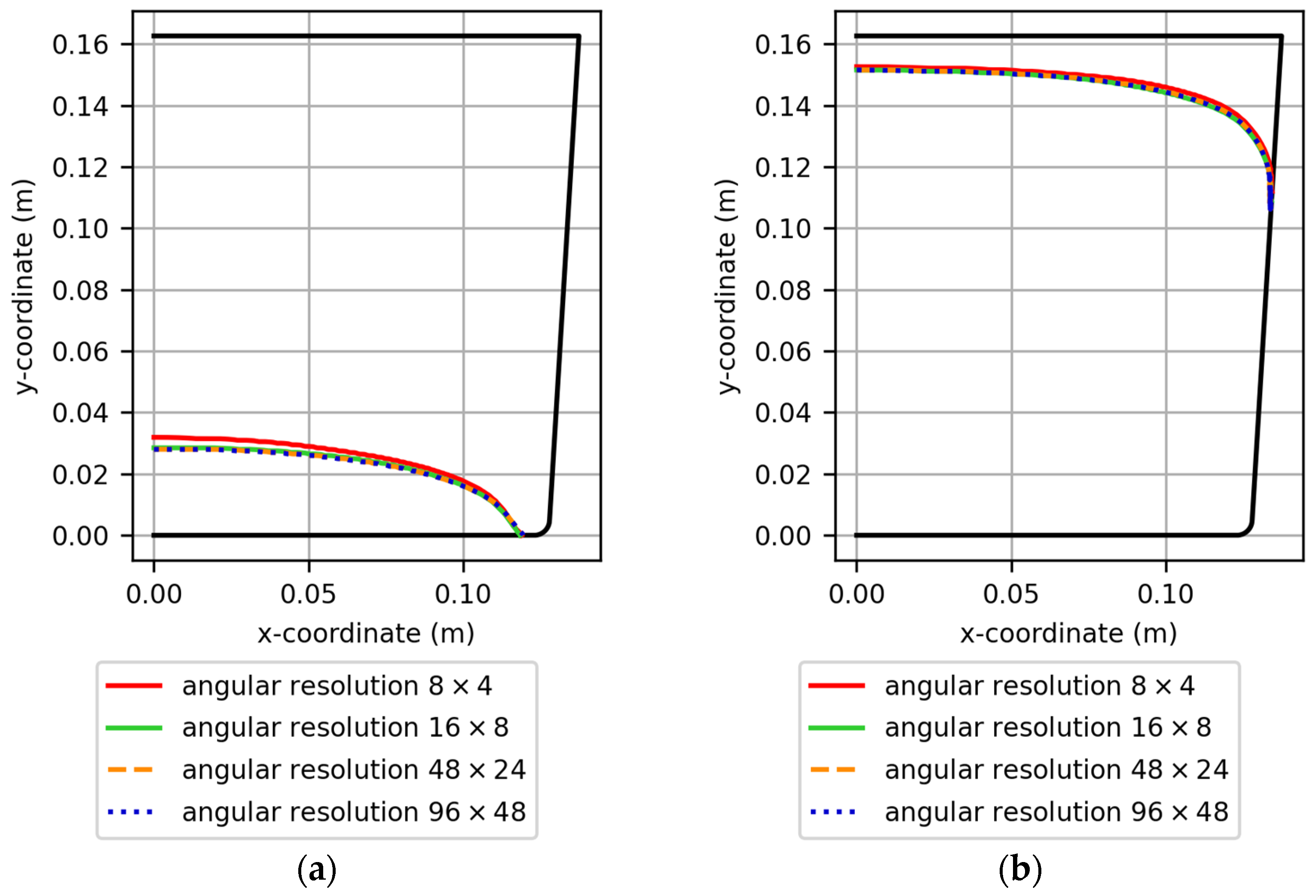
The investigations of the angular discretization were performed using the high-resolution mesh with a grid size of 0.5 mm in the sapphire zone and a mushy zone parameter of 1010 kgm−3s−1. The m-c interfaces were extracted as iso-lines with a solid-phase fraction of 0.5. The angular resolutions expressed in N φ × N θ were 8 × 4, 16 × 8, 48 × 24 and 96 × 48. The simulations were performed for the seeding stage as well as the stage with almost completed solidification (Figure 2). The results show that the qualitative shape of the m-c interface is already obtained at an angular resolution of 8 × 4. The deviations of the m-c interfaces decrease with increasing angular resolution.
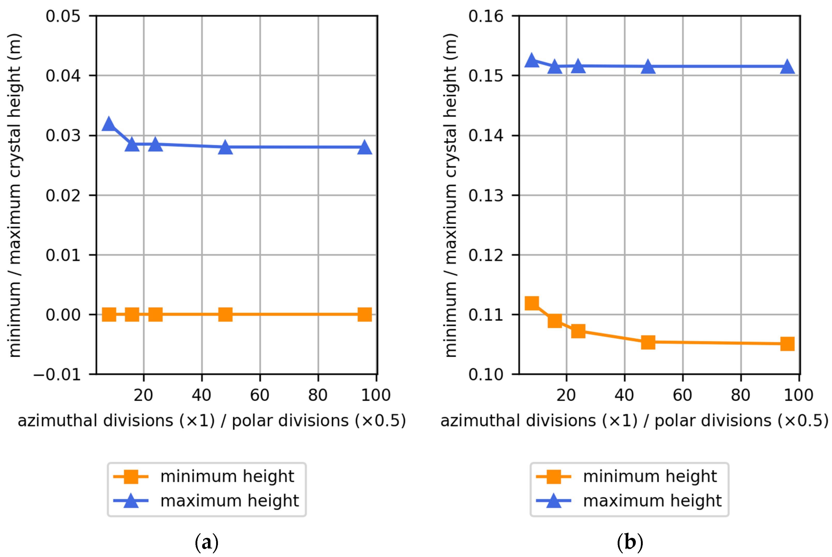
The refinement of the angular resolution is monitored via the height of the m-c interface at the axis and at the crucible wall (Figure 3). In the seeding stage, the height at the axis remains relatively constant at angular resolutions of 24 × 12 and higher. The m-c interface meets the crucible wall at the bottom; hence, a constant height is observed. In the stage with almost completed solidification, the height of the m-c interface in the axis remains constant at resolutions of 16 × 8 and higher. The m-c interface height at the wall, however, is found to change up to an angular resolution of 48 × 24. The m-c interface and the crucible wall meet at a flat angle, which leads to a wedge-shaped zone of liquid sapphire separating the crucible wall from the sapphire crystal. The near-wall zone displays higher sensitivity to the angular resolution compared to the other regions of the m-c interface. The selection of the appropriate angular resolution depends first and foremost on the purpose of the underlying study. Detailed analysis of the m-c interfaces requires correspondingly high angular resolutions. A fine angular resolution is also required in the context of locally resolved heat flux analysis due to the difference in thermophysical properties between crystal and melt. Secondly, also the computational efficiency is a relevant factor. The angular resolution of the finite volume radiation model is a major determinant of the computation time. As for example, the evaluation of the model with an angular resolution of 96 × 48 and a mesh size of 0.5 mm in the sapphire zone requires an average total wall-clock time of 3.89 s per iteration on a High-Performance Computing (HPC) workstation with AMD processors (x86_64 architecture), whereby 40 processors were used for the calculation. A reduction in the angular resolution to 16 × 8 (while maintaining the mesh size of 0.5 mm) reduces the computation time to 0.18 s per iteration. In comparison, also the influence of the mesh size was studied. Applying an angular resolution of 16 × 8 in combination with a coarsening of the mesh to an element size of 3 mm in the sapphire zone, which reduces the overall element number from 122,261 to 31,235, leads to an average computation time of 0.08 s per iteration.

3.2. Combined Influence of Grid and Mushy Zone Parameter

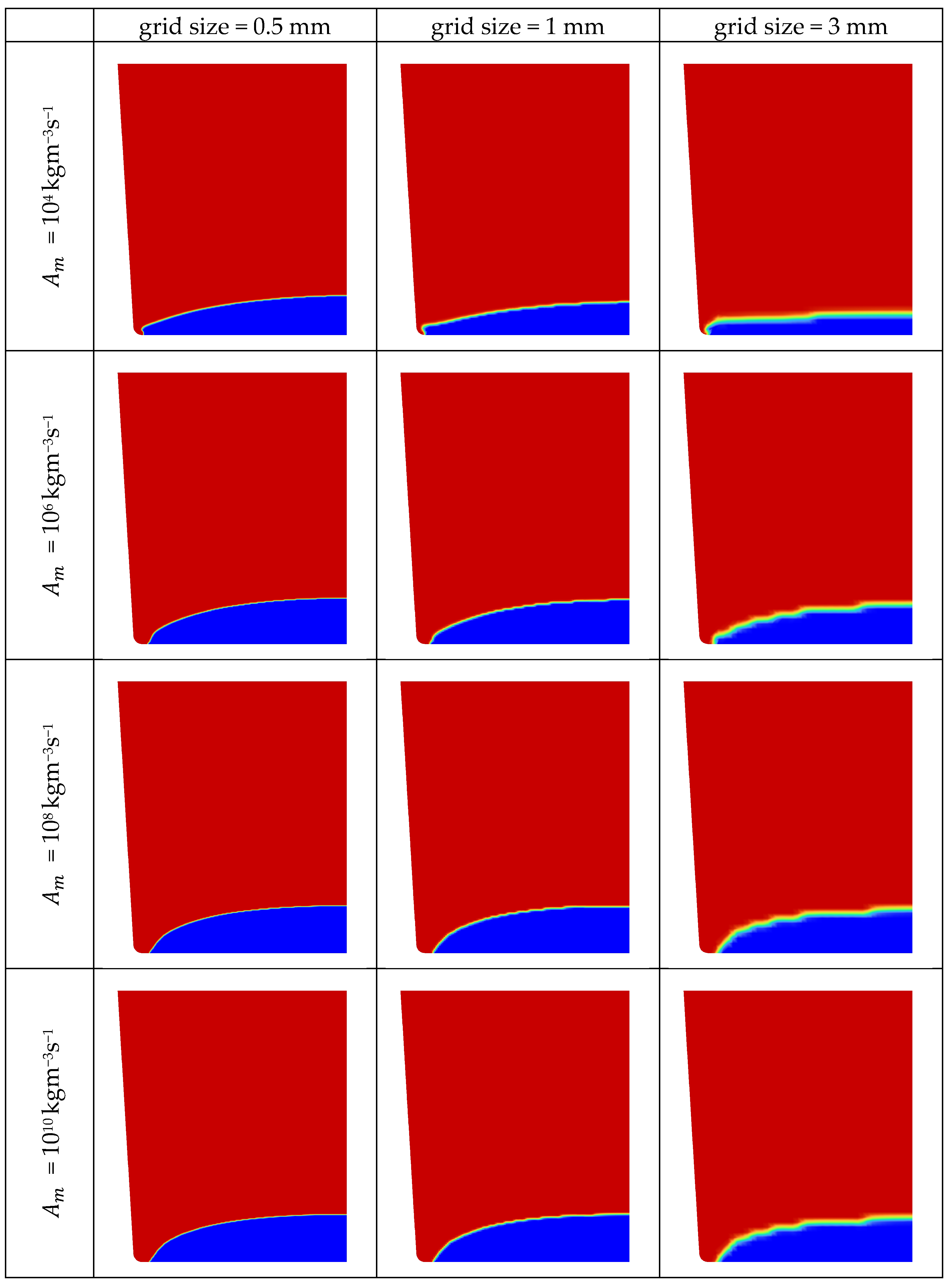
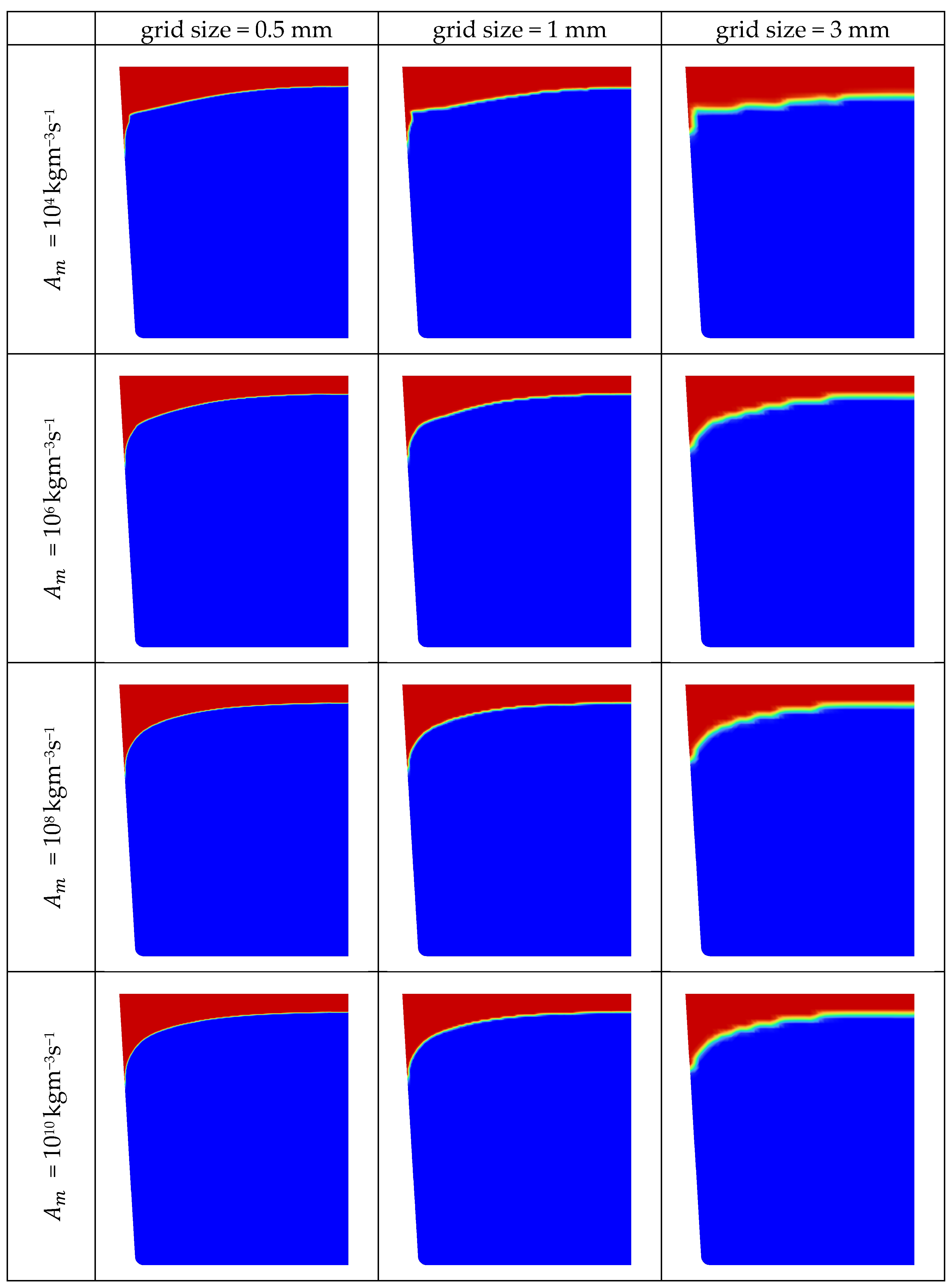
Based on the investigation of the angular resolution of the finite volume radiation model and the focus on the screening of a high number of grid sizes and mushy zone parameters and their interaction rather than on the near crucible wall region of the m-c interface as well as due to considerations of computational efficiency, an intermediate angular resolution was selected. In accordance with [9,19,21], 16 × 8 was chosen as an angular resolution for the study of the combined influence of grid and mushy zone parameter. The mushy zone parameter was varied between 104 kgm−3s−1 and 1010 kgm−3s−1. The considered grid sizes in the sapphire zone were 0.5 mm, 1 mm and 3 mm. Two stages, the seeding stage (Figure 4) and the stage where the solidification is almost completed (Figure 5), were investigated. In general, the size of the fixed grid controls the interface resolution. The thickness of the interface increases with grid size. In addition, a coarse grid leads to a stair-step structure of the m-c interface, which prevails at all investigated mushy zone parameters. With lower grid sizes, the m-c interface becomes smoother and the influence of the grid size decreases. When analyzing the influence of the mushy zone parameter in the seeding stage at the highest mesh resolution, significant differences in the shape of the crystal between high and low mushy zone parameters are observed. These differences relate to the zone of the m-c interface around the axis and to a higher degree to the zone where the m-c interface meets the bottom wall of the crucible. The m-c interface is slightly convex near the axis. The maximum height of the interface increases with increasing mushy zone parameters. The angle at which the interface meets the bottom wall of the crucible changes from obtuse to acute at a mushy zone parameter of 106 kgm−3s−1.
In the stage with an almost solidified crystal, again a significant influence of the mushy zone parameter is observed, which is highest in the near-wall region. At mushy zone parameters up to 106 kgm−3s−1, the m-c interface forms a pronounced kink near the side wall of the crucible. The lower the mushy zone parameter, the sharper the kink. The m-c interface is slightly convex between the axis and the kink. Further towards the crucible wall, it is characterized by a steep section, which is followed by a slightly curved section before it meets the wall of the crucible at a flat angle. The formed wedge-shaped gap is filled with liquid sapphire and separates the crystal from the side wall of the crucible. At mushy zone parameters between 106 kgm−3s−1 and 108 kgm−3s−1, the kink disappears, and a smooth m-c interface prevails, which, however, still meets the crucible at a flat angle.
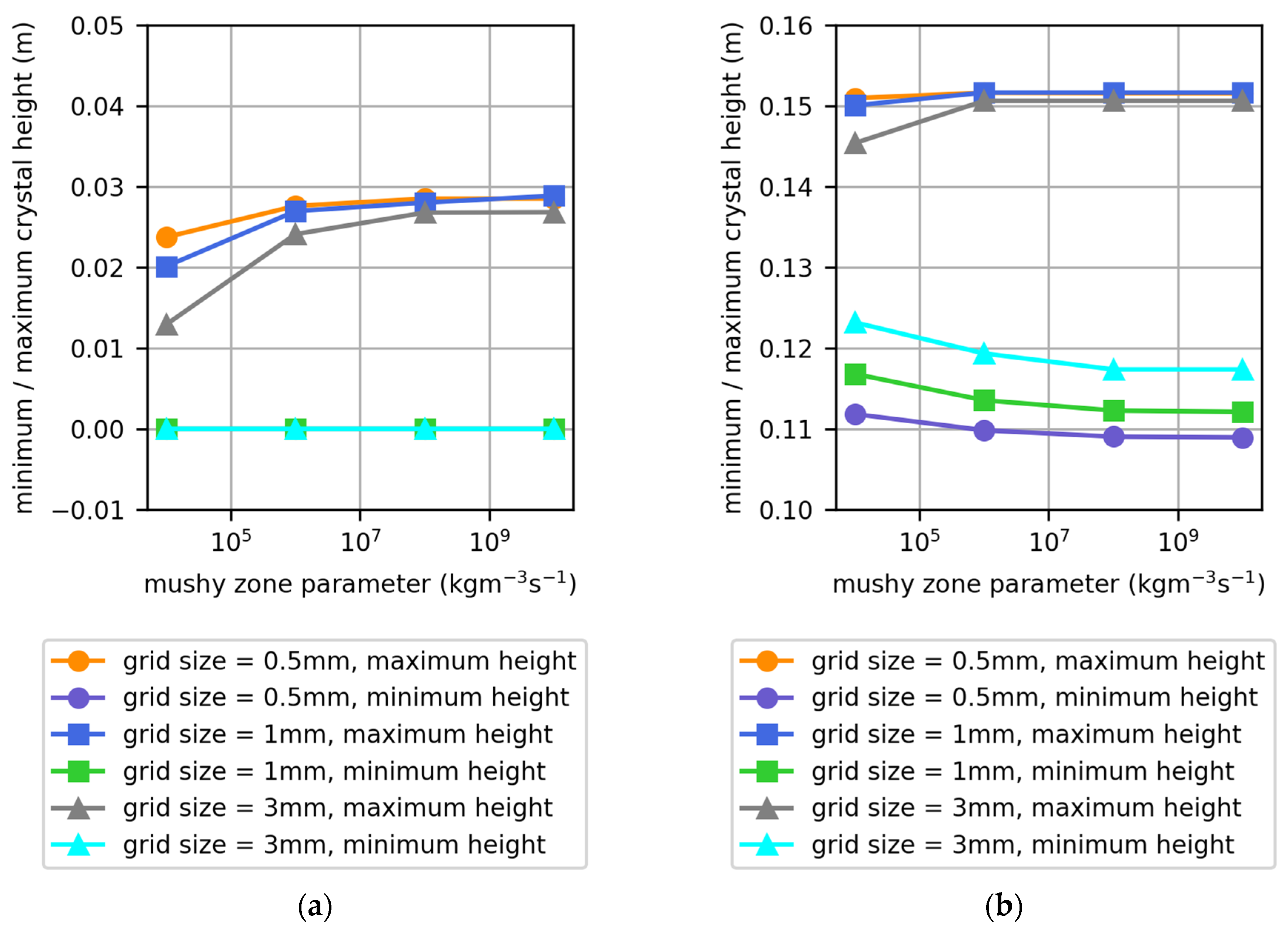
Convergence of the m-c interface is monitored with respect to the grid size and the mushy zone parameter considering the seeding stage and the stage where the solidification is almost completed (Figure 6). In the seeding stage, grid convergence at the axis position is obtained for grid sizes of 1 mm, provided that the mushy zone parameter is equal to or higher than 106 kgm−3s−1. The influence of the mushy zone parameter is characterized by a saturation of the height of the m-c interface at the axis at values of 108 kgm−3s−1. In the stage where the crystal is almost solidified, the convergence of the heights of the m-c interface at the axis and near the crucible wall is different. It converges at a grid size of 1 mm at the axis position. The height of the m-c interface at the crucible wall does not show convergence with respect to the studied grid sizes. The finer the grid, the lower the height at any mushy zone parameter. The influence of the mushy zone parameter results in a saturation of the height of the m-c interface at the axis at values 106 kgm−3s−1 while the crystal height at the crucible wall remains constant at a mushy zone parameter of 108 kgm−3s−1 and higher.
The findings compare well with studies related to thermal energy storage systems. For example, in accordance with Ebrahimi et al. [27], for the isothermal phase transformation, a decreasing sensitivity on the mushy zone parameter with increasing mesh fineness was observed. Ebrahimi et al. [27] found that at a non-dimensional cell size of 3.33 × 10⁻³, the discernable differences between A m = 104 kgm−3s−1 and A m = 108 kgm−3s−1 were almost diminished. In the prevalent study of sapphire growth, a non-dimensional cell size of 3.08 × 10⁻³ was used. However, although the decreasing sensitivity with decreased mesh size, still a pronounced difference in the m-c interfaces between A m = 104 kgm−3s−1 and A m = 108 kgm−3s−1 is found. Independence from the mushy zone parameter is reached at comparatively high values. The suppression of the velocity field in the solid zone requires the sink term in the momentum equation to be sufficiently high compared to the viscous term [27]. Since the viscosity of the sapphire melt is more than one order of magnitude higher than that of the artificial material used by [27], higher mushy zone parameters are required to ensure independence. The decreasing influence of the mushy zone parameter with the decreasing size of the grid cells is attributed to the decreasing volume of the transition zone between crystal and melt, where the mushy zone parameter affects the results [27,30].

3.3. Physically Determined Interface Shape

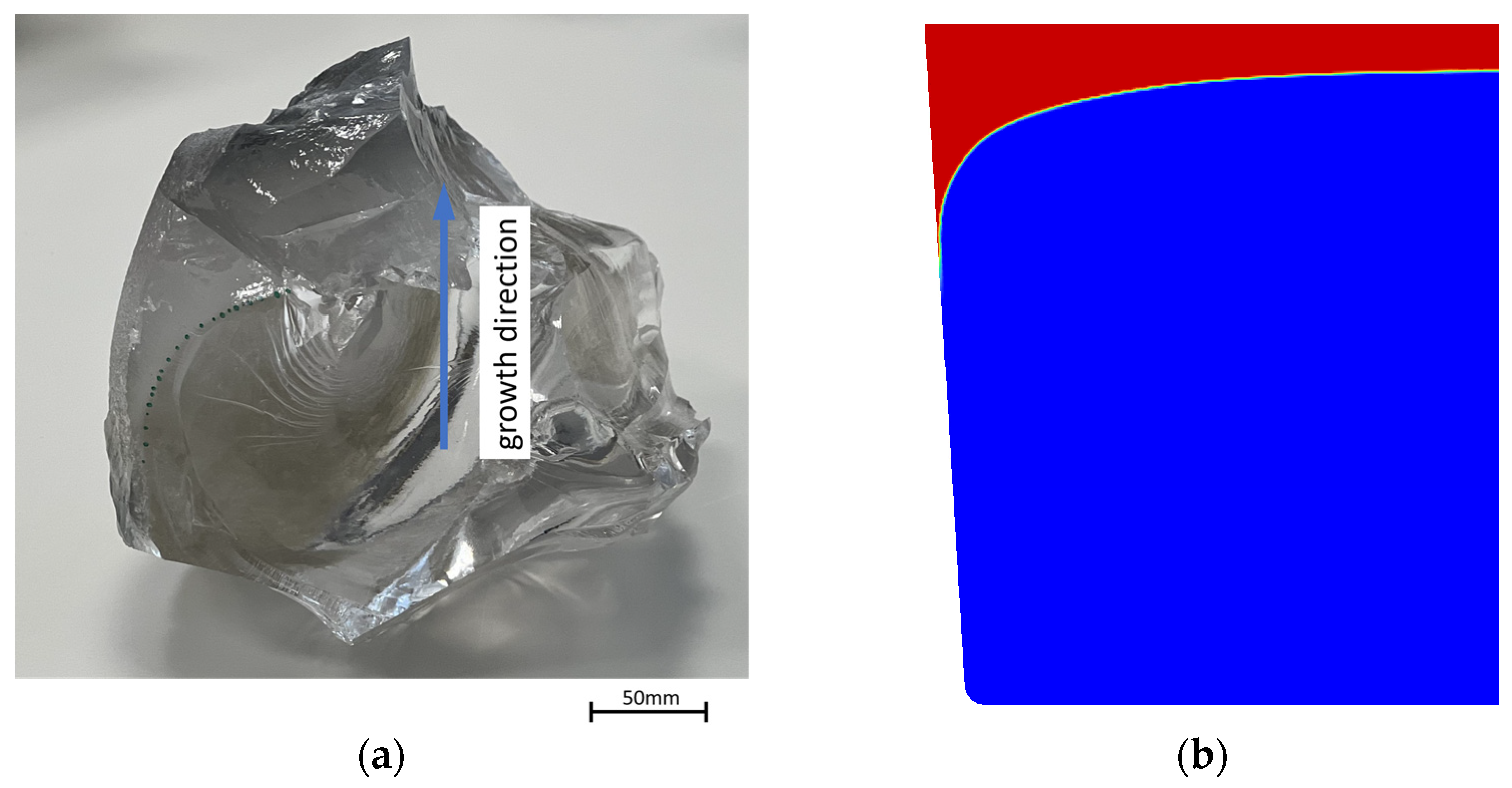
A reference for the features of the shape of the m-c interface is obtained from an industrial HEM growth process. Specifically, the applied growth process uses the FAMETEC McSap technology EP4271856A1 [31] and WO2023212765A1 [32], which is based on the HEM method of crystal growth from the melt phase. In this process, raw Alumina material is placed on top of a crystal seed of the orientation of interest. The heater power is ramped up to achieve melting while the bottom of the crucible is subjected to cooling to protect the seed from complete melting. When melting proceeds till full melting of Alumina raw material and partial melting of the seed, the process is reversed to solidification by carefully ramping down the heaters and strengthening the cooling flux from the crucible bottom surface. As illustrated in Figure 1, the growth is conducted in the presence of both top heaters and side heaters with which under the specific hot zone design of the furnace, the control over the axial/radial temperature gradient—determining the interface shape—is fulfilled. At the end of the growth, a careful power ramp down to the room temperature is carried out. The process was halted by a power shutdown. Subsequent to full solidification and cooling down to room temperature, the sapphire boule was analyzed as shown in Figure 7. The analysis procedure essentially follows the method for the extraction of an intermediate-stage m-c interface of a sapphire single crystal proposed by Qi et al. [19]. The region above the m-c interface was mechanically removed in parts by applying sawing and chiseling, which is facilitated by the lower strength of the rapidly solidified liquid compared to the single crystal below. The rapid cooling reveals the m-c interface, which is highlighted by the dashed line in Figure 7a. The m-c interface shows a rounded shape, which is flat and almost horizontal near the axis of the boule. Towards the side wall of the crucible, it displays a convex curvature and meets the side wall at a flat angle. These features are observed in the simulations with a high angular resolution for radiative transport (16 × 8), a fine grid in the sapphire zone (0.5 mm) and a high mushy zone parameter ( 108 kgm−3s−1). The m-c interface obtained from the simulation is shown in Figure 7b.

3.4. Thermal Analysis of Process States

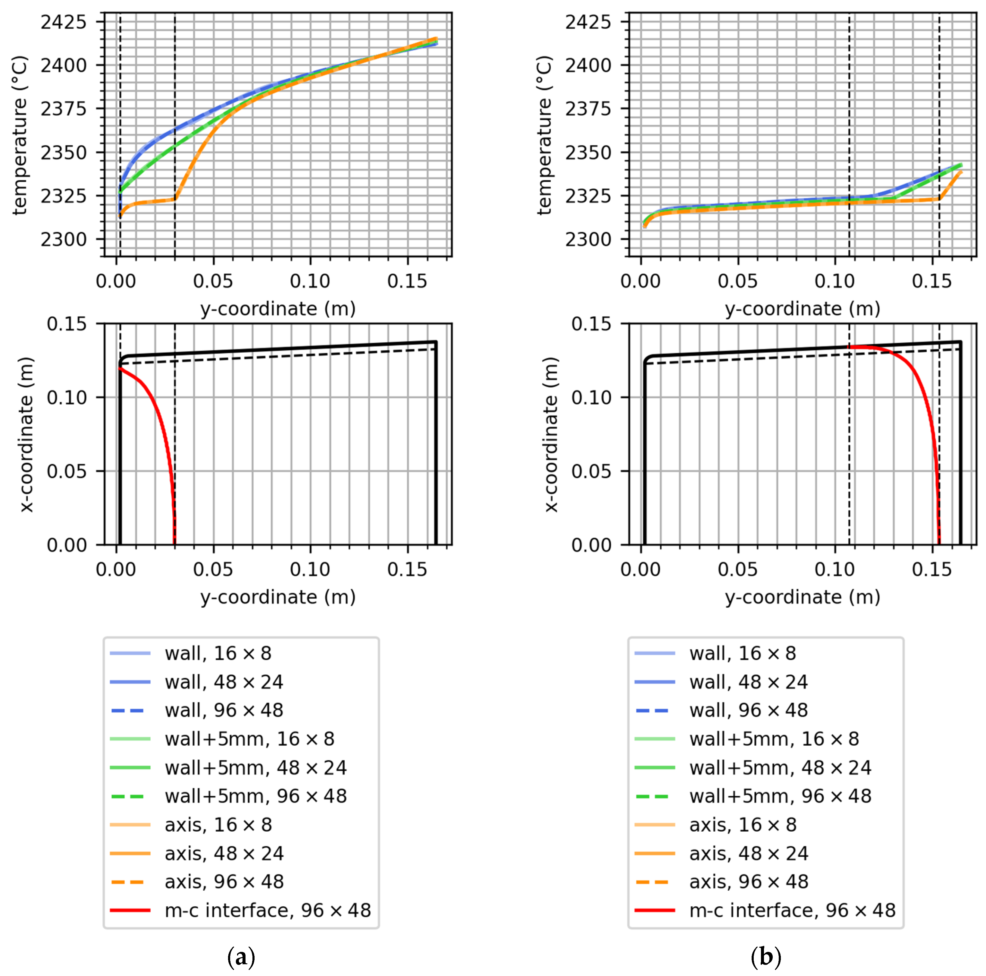
For the thermal analysis, a grid size of 0.5 mm and a mushy zone parameter of 1010 kgm−3s−1 were selected. The angular resolutions of the finite volume radiation model were 16 × 8, 48 × 24 and 96 × 48. Three temperature evaluation paths were defined in the sapphire zone. One path along the axis, one path along the side wall of the crucible and one path parallel to the side wall at a distance of 5 mm. Figure 8 shows the paths and resulting temperature distributions for the seeding stage and the stage with almost completed solidification together with the m-c interfaces. The positions of the m-c interfaces at the axis and crucible wall are indicated by thin dashed lines, correlating the positions with the temperature profiles.
In the seeding stage, a smooth temperature profile is obtained at the crucible side wall and as well as on the parallel path at a distance of 5 mm. The path along the axis is the only path that intersects with the m-c interface. The intersection corresponds with a kink in the temperature profile. In the stage with almost completed solidification, all paths intersect with the m-c interface and display a kink, which is more pronounced along the axis and less pronounced at the crucible wall. In both stages, a pronounced decrease in the temperature in the crystal close to the bottom of the crucible is observed. The described features of the axial temperature profile are well in line with that obtained by Qi et al. [19]. Also, Ma et al. [9,33] performed evaluations of the axial temperature profile, which showed the observed features with a steep decrease in temperature near the bottom of the crystal and a change in slope at the m-c interface.
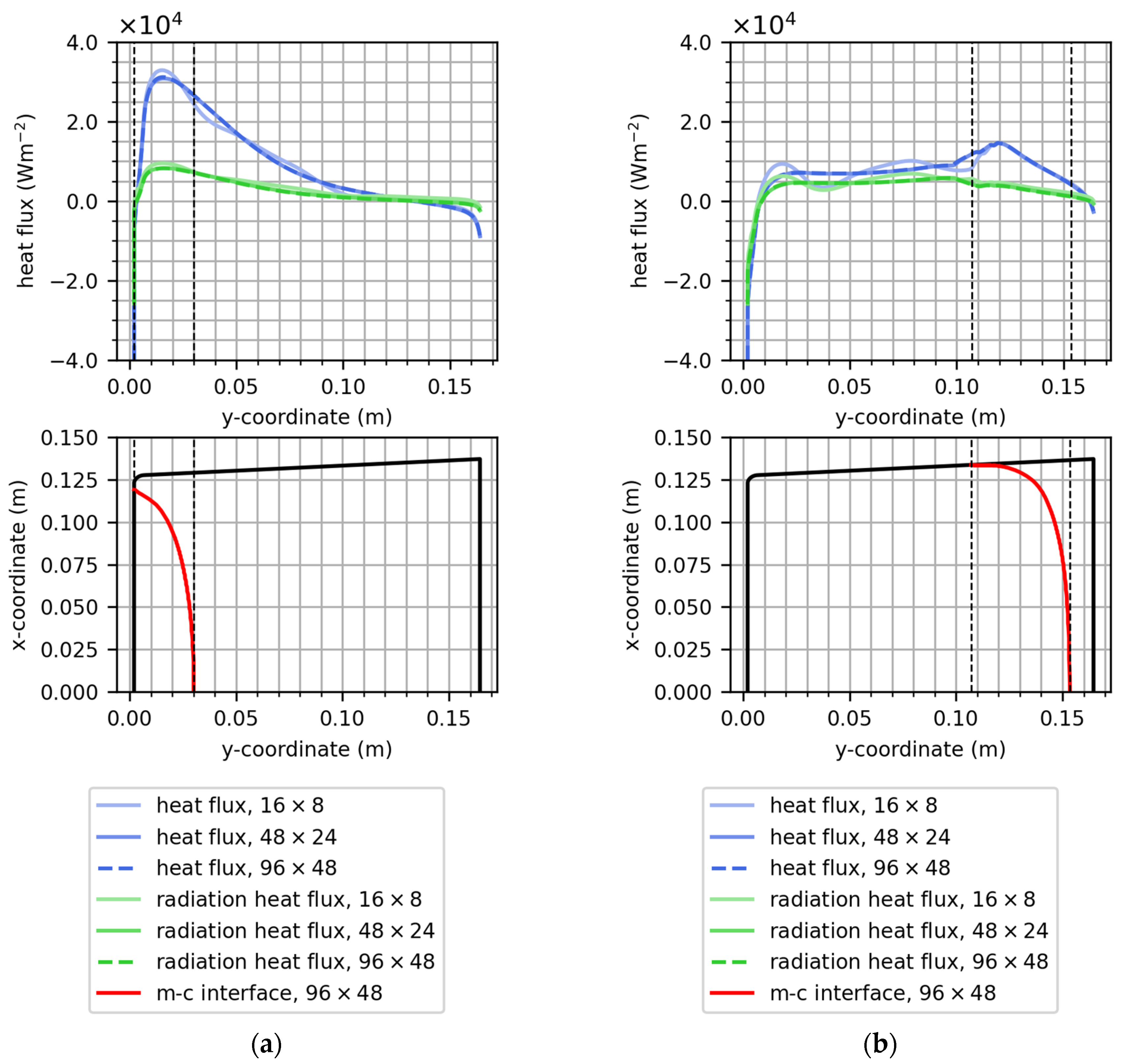
Figure 9 shows the total and radiation heat flux at the crucible side wall for both stages of solidification together with the m-c interfaces. In the seeding stage, the total and radiation heat flux towards the sapphire shows a pronounced peak at the position of the m-c interface. These characteristics are attributable to the cooling imposed at the bottom, enhanced heat flux via radiation through the crystal and the lateral heating from the side heaters. Qi et al. [19] also described a peak of the heat flux at the m-c interface, which in their study depended on the absorption coefficient of the melt, whereby the peak was observed at a l = 2900 m−1 and diminished at a l = 80 m−1. The heat fluxes towards the sapphire are lower in the upper zone, and immediately below the free surface of the melt, a loss of heat is observed. This is explained by the intense heating from the top heaters surpassing the influence of the side heaters. In the stage with an almost completed solidification, a maximum of the total and radiation heat flux at the position of the m-c interface still prevails, although it is lower compared to the seeding stage. In the melt zone, the heat flux is dominated by conduction, which can be attributed to the high absorption coefficient of the melt ( a l = 1019.0 m−1). The heat flux towards the crystal at the side wall as well as the ratio between total heat flux and radiation heat flux is comparatively uniform. In the crystalline zone, the contribution of the radiative heat flux is approximately two-thirds of the total heat flux. The higher contribution of the radiative heat transfer is supported by the comparatively low absorption coefficient in the crystal ( a s = 19.26 m−1). In the uppermost part of the melt, an outwards flux of heat is observed and attributed to the different heating intensities of the top and side heaters. The higher contribution of radiative flux to the total heat flux in the zone where the crystal prevails compared to the zone with the melt is fostered by Qi et al. [19]. According to their study, a low absorption coefficient of the melt ( a l = 80 m−1) leads to almost equal contributions of radiative and conductive heat fluxes to the overall heat flux in the melt zone. At a higher absorption coefficient ( a l = 2900 m−1), the contribution of the radiative heat flux was only a small portion of that of the conductive heat flux.
In view of the sensitivity of the m-c interface position in the near-wall region, the effect of angular resolution is examined. The temperature and heat flux evaluations are depicted by lightened lines for low angular resolutions in Figure 8 and Figure 9, respectively. While the temperature distributions along the evaluation paths were only changed to a very low degree, the radiative and total heat flux distribution along the entire side wall of the crucible are significantly affected by the angular resolutions. The heat fluxes display spatial fluctuations at angular resolutions of 16 × 8. The heat fluxes obtained with an angular resolution of 48 × 24 remained constant on further refinement to 96 × 48.

4. Conclusions

Selected aspects of the numerical simulation of the m-c interface in a HEM sapphire growth process have been examined. Two stages of crystal growth were simulated, which correspond to the seeding stage and the stage where the solidification is almost completed.
The dependency of the m-c interface on the mushy zone parameter was elaborated, and it could be shown that convergence is obtained with relatively high mushy zone parameters 108 kgm−3s−1. The resolution of the m-c interface strongly depends on the grid size, whereby severely coarse grids can lead to artifacts such as a stair-step structure of the m-c interface. While most of the m-c interface converges at a grid size of 1 mm, the region near the side wall of the crucible could be shown to be highly sensitive to the grid resolution. Similar observations related to the region near the side wall were made when investigating the angular resolution of the RTE. While most of the m-c interface remained unchanged at angular resolutions higher than 16 × 8, the near-wall region remained sensitive to the angular resolution up to resolutions of 48 × 24. The features of the m-c interface compare qualitatively well with a physically determined interface shape obtained from an HEM growth process. The corresponding model settings consist of an angular resolution of 16 × 8, a grid size of 0.5 mm and a mushy zone constant 108 kgm−3s−1. Two process states were studied in terms of the heat flux towards the side wall of the crucible. The results show that heat transport is dominated by radiation where the crystal prevails, whereas in the zone with liquid sapphire, only a smaller fraction of the heat is transferred via radiation. A pronounced peak of the heat flux to the crucible side wall is found in the zone around the m-c interface in both stages of crystal growth. As for the m-c interface in the near-wall region of the crucible, a high resolution of 48 × 24 is demonstrated to be especially important for the detailed analysis of the heat flux distributions along walls. The herein-discussed aspects are determinants in the setup of high-resolution numerical models, fostering the careful adjustment of thermal conditions in HEM furnaces, for example, via the optimization of heat input and thermal fields to optimize crystal quality and energy efficiency. Future work is focused on the reduction in internal stresses in the crystal by the reduction in thermal strains and enhancement of the sustainability by reducing power consumption.

Author Contributions

Conceptualization, W.E.; methodology, W.E., R.A.T., M.S., G.R. and S.L.; validation, S.L.; investigation, W.E. and S.L.; writing—original draft preparation, W.E.; writing—review and editing, S.L., G.R., P.R., R.A.T. and M.S.; visualization, W.E. and S.L.; project administration, S.L.; funding acquisition, S.L. All authors have read and agreed to the published version of the manuscript.

Funding

This project receives funding from FAMETEC GmbH and the Austrian Research Promotion Agency FFG.

Data Availability Statement

The original contributions presented in this study are included in the article. Further inquiries can be directed to the corresponding author.

Conflicts of Interest

Sina Lohrasbi is employed by the company FAMETEC GmbH. The remaining authors are employed at Materials Center Leoben Forschung GmbH. The project receives funding from FAMETEC GmbH and the Austrian Research Promotion Agency FFG.

References

  1. Akselrod, M.S.; Bruni, F.J. Modern trends in crystal growth and new applications of sapphire. J. Cryst. Growth 2012, 360, 134–145. [Google Scholar] [CrossRef]
  2. Bruni, F.J. Crystal growth of sapphire for substrates for high-brightness, light emitting diodes. Cryst. Res. Technol. 2015, 50, 133–142. [Google Scholar] [CrossRef]
  3. Kappers, M.J.; Moram, M.A.; Sridhara Rao, D.V.; McAleese, C.; Humphreys, C.J. Low dislocation density GaN growth on high-temperature AlN buffer layers on (0 0 0 1) sapphire. J. Cryst. Growth 2010, 312, 363–367. [Google Scholar] [CrossRef]
  4. Klunnikova, Y.V.; Malyukov, S.P.; Filomonov, A.V.; Zhang, N. Analysis of heat transfer processes for sapphire growth by horizontal directed crystallization method. J. Adv. Dielectr. 2020, 10, 2060001. [Google Scholar] [CrossRef]
  5. Hu, K.; Zheng, L.; Zhang, H. Control of interface shape during high melting sesquioxide crystal growth by HEM technique. J. Cryst. Growth 2018, 483, 175–182. [Google Scholar] [CrossRef]
  6. Tang, H.; Li, H.; Xu, J. Growth and development of sapphire crystal for LED applications. In Advanced Topics on Crystal Growth; Ferreira, S., Ed.; InTech: Rijeka, Croatia, 2013; pp. 307–333. [Google Scholar]
  7. Wu, M.; Zhao, W.; Liu, L.; Yang, Y.; Ma, W. Yuan Wang Effects of crucible cover on heat transfer during sapphire crystal growth by heat exchanger method. J. Cryst. Growth 2014, 404, 130–135. [Google Scholar] [CrossRef]
  8. He, Y.; Hua, Z.; Chen, M.; Tang, T.; Han, J. Numerical simulation of the sapphire growth process using a self-regulating thermal boundary condition method. Appl. Therm. Eng. 2018, 132, 87–94. [Google Scholar] [CrossRef]
  9. Ma, W.; Zhao, L.; Ding, G.; Yang, Y.; Lv, T.; Wu, M.; Liu, L. Numerical study of heat transfer during sapphire crystal growth by heat exchanger method. Int. J. Heat Mass Transf. 2014, 72, 452–460. [Google Scholar] [CrossRef]
  10. Zhang, N.; Park, H.G.; Derby, J.J. Simulation of heat transfer and convection during sapphire crystal growth in a modified heat exchanger method. J. Cryst. Growth 2013, 367, 27–34. [Google Scholar] [CrossRef]
  11. Chen, J.-C.; Lu, C.-W. Influence of the crucible geometry on the shape of the melt–crystal interface during growth of sapphire crystal using a heat exchanger method. J. Cryst. Growth 2004, 266, 239–245. [Google Scholar] [CrossRef]
  12. Lu, C.-W.; Chen, J.-C. Numerical computation of sapphire crystal growth using heat exchanger method. J. Cryst. Growth 2001, 225, 274–281. [Google Scholar] [CrossRef]
  13. Wu, M.; Liu, L.; Ma, W. Control of melt-crystal interface shape during sapphire crystal growth by heat exchanger method. J. Cryst. Growth 2017, 474, 31–36. [Google Scholar] [CrossRef]
  14. Demina, S.E.; Bystrova, E.N.; Postolov, V.S.; Eskov, E.V.; Nikolenko, M.V.; Marshanin, D.A.; Yuferev, V.S.; Kalaev, V.V. Use of numerical simulation for growing high-quality sapphire crystals by the Kyropoulos method. J. Cryst. Growth 2008, 310, 1443–1447. [Google Scholar] [CrossRef]
  15. Liu, W.; Lu, J.; Chen, H.; Yan, W.; Min, C.; Lian, Q.; Wang, Y.; Cheng, P.; Liu, C.; Xu, Y. Study on crystal-melt interface shape of sapphire crystal growth by the KY method. J. Cryst. Growth 2015, 431, 15–23. [Google Scholar] [CrossRef]
  16. Miyagawa, C.; Kobayashi, T.; Taishi, T.; Hoshikawa, K. Demonstration of crack-free c-axis sapphire crystal growth using the vertical Bridgman method. J. Cryst. Growth 2013, 372, 95–99. [Google Scholar] [CrossRef]
  17. Hoshikawa, K.; Taishi, T.; Ohba, E.; Miyagawa, C.; Kobayashi, T.; Yanagisawa, J.; Shinozuka, M. Vertical Bridgman growth of sapphire crystals, with thin-neck formation process. J. Cryst. Growth 2014, 401, 146–149. [Google Scholar] [CrossRef]
  18. Tavakoli, M.H. Numerical Study of Heat Transport and Fluid Flow of Melt and Gas during the Seeding Process of Sapphire Czochralski Crystal Growth. J. Cryst. Growth 2008, 310, 3107–3112. [Google Scholar] [CrossRef]
  19. Qi, X.; Ma, W.; Liu, L. Effect of Internal Radiation on Heat Transfer during Ti:sapphire Crystal Growth Process by Heat Exchanger Method. Int. J. Heat Mass Transf. 2021, 170, 121000. [Google Scholar] [CrossRef]
  20. Trasca, R.A.; Sistaninia, M.; Reiss, G.; Eßl, W.; Raninger, P.; Lohrasbi, S. Coupled Thermal Solidification Process Simulation of Sapphire Growth. Integr. Mater. Manuf. Innov. 2024, 13, 1–13. [Google Scholar] [CrossRef]
  21. Wu, M.; Liu, L.; Yang, Y.; Zhao, W.; Ma, W. Effect of Crucible Location on Heat Transfer in Sapphire Crystal Growth by Heat Exchanger Method. Heat Transf. Eng. 2016, 37, 332–340. [Google Scholar] [CrossRef]
  22. Ma, W.; Zhao, W.; Wu, M.; Ding, G.; Liu, L. Temperature and thermal stress evolutions in sapphire crystal during the cooling process by heat exchanger method. J. Cryst. Growth 2017, 474, 37–42. [Google Scholar] [CrossRef]
  23. Ma, W.; Liu, L. Role of Internal Radiation in Oxide Crystal Growth by Heat Exchanger Method. Crystals 2017, 7, 18. [Google Scholar] [CrossRef]
  24. Vogel, J.; Felbinger, J.; Johnson, M. Natural convection in high temperature flat plate latent heat thermal energy storage systems. Appl. Energy 2016, 184, 184–196. [Google Scholar] [CrossRef]
  25. Fadl, M.; Eames, P.C. Numerical investigation of the influence of mushy zone parameter Amush on heat transfer characteristics in vertically and horizontally oriented thermal energy storage systems. Appl. Therm. Eng. 2019, 151, 90–99. [Google Scholar] [CrossRef]
  26. Ezzat, Y.; Sakr, R.Y.; Abdel-Rehim, A.A. Numerical investigation of the effect of thermal expansion coefficient and mushy zone constant on modelling of the phase change process to provide reliable selection criteria of modelling parameters. J. Energy Storage 2023, 72, 108771. [Google Scholar] [CrossRef]
  27. Ebrahimi, A.; Kleijn, C.R.; Richardson, I.M. Sensitivity of Numerical Predictions to the Permeability Coefficient in Simulations of Melting and Solidification Using the Enthalpy-Porosity Method. Energies 2019, 12, 4360. [Google Scholar] [CrossRef]
  28. ANSYS Inc. Ansys Fluent Theory Guide 2021 R2; ANSYS Inc.: Canonsburg, PA, USA, 2021. [Google Scholar]
  29. Voller, V.R.; Prakash, C. A fixed grid numerical modelling methodology for convection-diffusion mushy region phase-change problems. Int. J. Heat Mass Transf. 1987, 30, 1709–1719. [Google Scholar] [CrossRef]
  30. Mencinger, J. Numerical simulation of melting in two-dimensional cavity using adaptive grid. J. Comput. Phys. 2004, 198, 243–264. [Google Scholar] [CrossRef]
  31. Barbar, G.; Ebner, R.; Park, J.K.; Sen, G. Process for Manufacturing a Monocrystalline Crystal, in Particular a Sapphire. EP4271856A1, 28 January 2021. [Google Scholar]
  32. Ebner, R.; Park, J.; Sen, G.; Lohrasbi, S.; Bürscher, M. Device and Method for Producing an Artificial Sapphire Single Crystal. WO2023212765A1, 5 May 2023. [Google Scholar]
  33. Ma, W.; Liu, L. Investigation of heat transfer and thermal stress during sapphire crystal growth process by heat exchanger method: Evaluation of radiation models. J. Cryst. Growth 2017, 468, 909–913. [Google Scholar] [CrossRef]
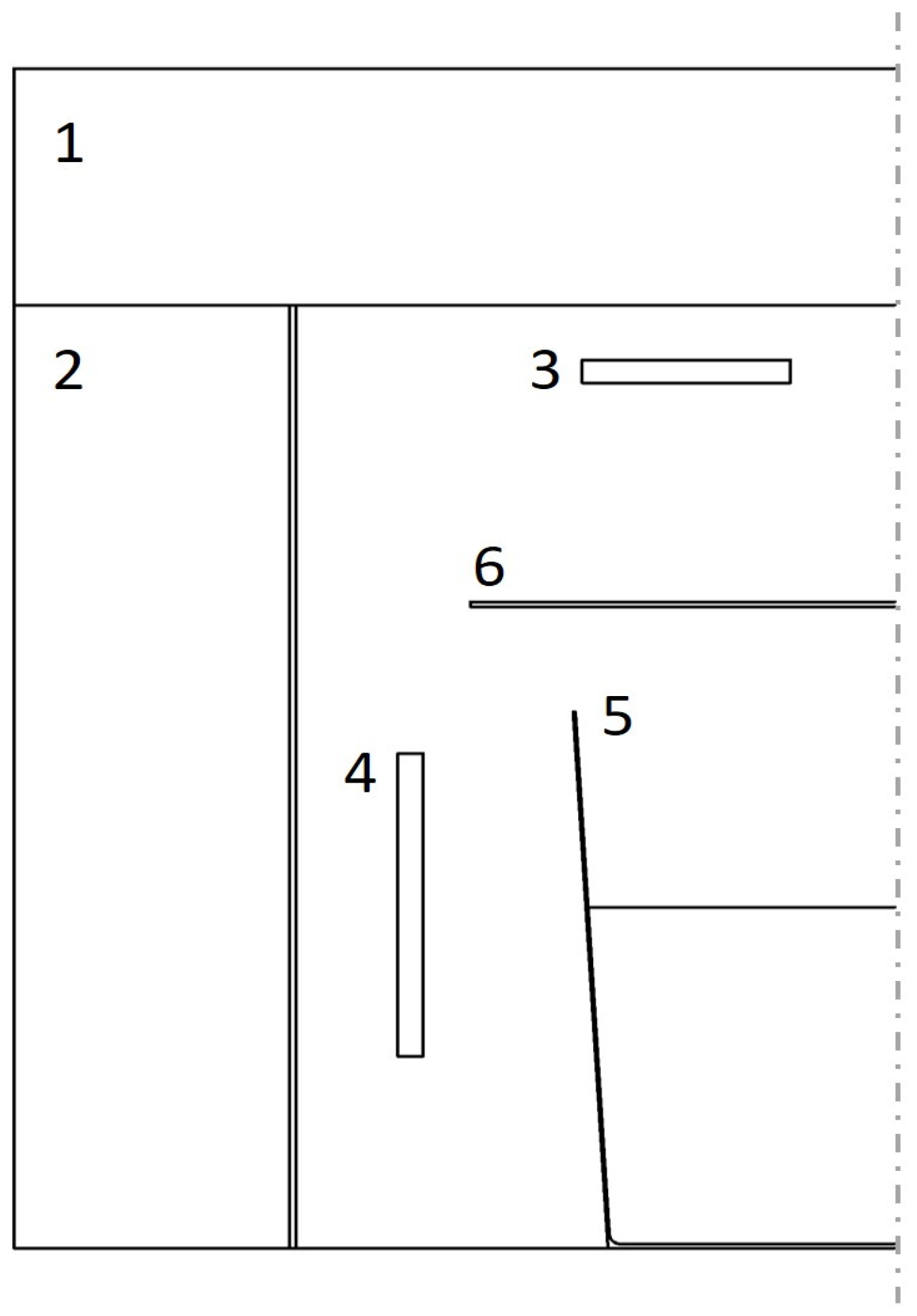
Figure 1. Axisymmetric simulation domain consisting of top insulation (1), lateral insulation (2), top heater (3), side heater (4), crucible (5) and heat shield (6).
Crystals 14 01036 g001
Figure 2. The shape of the m-c interface with different angular resolutions denoted by N φ × N θ with φ and θ referring to the azimuthal and the polar angle, respectively: (a) the seeding stage and (b) the stage with almost completed solidification.
Crystals 14 01036 g002
Figure 3. Influence of the angular resolution on the height of the m-c interface in the axis and at the crucible wall: (a) the seeding stage and (b) the almost completed solidification.
Crystals 14 01036 g003
Figure 4. Combined influence of grid size and mushy zone parameter in the seeding stage.
Crystals 14 01036 g004
Figure 5. The combined influence of grid and mushy zone parameters in the stage with almost completed solidification.
Crystals 14 01036 g005
Figure 6. Influence of grid and mushy zone parameter: (a) the seeding stage and (b) the stage with almost completed solidification.
Crystals 14 01036 g006
Figure 7. (a) The m-c interface shape obtained from the experiment (FAMETEC GmbH) and (b) the m-c interface shape computed via the simulation model. An angular resolution for radiative transport of 16 × 8, a grid size of 0.5 mm in the sapphire zone and a mushy zone parameter of 108 kgm−3s−1 were applied in the simulation.
Crystals 14 01036 g007
Figure 8. (a) Temperature distribution in the seeding stage and (b) the stage with almost completed solidification.
Crystals 14 01036 g008
Figure 9. (a) Heat flux distribution in the seeding stage and (b) the stage with almost completed solidification.
Crystals 14 01036 g009
Table 1. Material data [13,14,15,19].
PropertyValueUnit
Viscosity   μ 0.057kgm−1s−1
Melting   temperature   T m 2323K
Absorption   coefficient   ( melt )   a l 1019.0m−1
Absorption   coefficient   ( crystal )   a s 19.26m−1
Refractive   index   n 1.781
Thermal   expansion   coefficient   β 1.8 × 10⁻⁵K−1
Mushy   zone   parameter   A m 104–1010kgm−3s−1
Crystallization   heat   L 1,407,000Jkg−1
Heat   capacity   c p 765Jkg−1K−1
Thermal   conductivity   ( melt )   λ l 3.5Wm−1K−1
Thermal   conductivity   ( crystal )   λ s 5.8Wm−1K−1
Mass   density   ρ 3000kgm−3
Marangoni   coefficient   ψ −3.5 × 10⁻⁵Nm−1K−1
Disclaimer/Publisher’s Note: The statements, opinions and data contained in all publications are solely those of the individual author(s) and contributor(s) and not of MDPI and/or the editor(s). MDPI and/or the editor(s) disclaim responsibility for any injury to people or property resulting from any ideas, methods, instructions or products referred to in the content.