Article

Revisiting the Crystallography of {225}γ Martensite: How EBSD Can Help to Solve Long-Standing Controversy

4MAT, Ecole Polytechnique de Bruxelles, Campus du Solbosch, Université Libre de Bruxelles, 1050 Brussels, Belgium
*
Author to whom correspondence should be addressed.
Crystals 2024, 14(3), 287; https://doi.org/10.3390/cryst14030287
Submission received: 29 February 2024 / Revised: 15 March 2024 / Accepted: 18 March 2024 / Published: 20 March 2024
(This article belongs to the Section Crystalline Metals and Alloys)

Abstract

:
Explaining the crystallography of iron alloys martensite with a {225}γ habit plane remains a challenging task within the phenomenological theory of martensite crystallography. The purpose of this study is to re-examine the martensite formed in a Fe-8Cr-1.1C alloy using EBSD, which has a better angular resolution than the conventional transmission electron diffraction techniques previously used. The results show that the single morphological plates, which hold a near {225}γ habit plane, are bivariant composites made up of two twin-related variants. It is shown that a {113}γ plane is systematically parallel to one of the three common 112 α planes between the two twin-related crystals. This observation suggests that the lattice invariant strain of transformation occurs through a dislocation glide on the {113}γ ⟨110⟩γ system, rather than through twinning as is commonly accepted. Based on this assumption, the predictions of Bowles and Mackenzie’s original theory are in good agreement with the crystallographic features of {225}γ martensite. Unexpectedly, it is the high shear solution of the theory that gives the most accurate experimental predictions.

1. Introduction

Martensite is a key microstructural feature of advanced high-strength steels [1,2]. Gaining new insights into the mechanisms of its formation is, therefore, highly desirable from a technological perspective. Due to its intrinsic ultra-fast kinetics, it seems impossible to follow the martensitic transformation that occurs in the bulk specimen in real-time, although the recent development of 4D single-pulse electron microscopy seems promising in this regard [3]. Due to its displacive nature, the martensitic transformation establishes a strong crystallographic relationship between the parent austenite and martensite. The study of these relationships has been the subject of almost all the studies on martensite since the earliest days, and it is still considered one of the most effective ways to gain a better understanding of the transformation [4,5]. Among the various particularities of the martensitic transformation in steels, the sudden change in the habit plane of plate martensite in iron alloys from 225 γ to 3   10   15 γ with increasing carbon content has been an intriguing phenomenon since the pioneering observations of the 1950s [6,7,8]. However, its origin still remains mostly unexplained. The phenomenological theories of martensite crystallography (PTMC) developed independently in the early 1950s by Wechsler et al. (WLR theory) and Bowles and MacKenzie (BM theory), accurately predict the orientation relationship (OR), the habit plane, and the shape deformation of 3   10   15 γ martensite [9,10]. This is a significant achievement for the theories. However, Wechsler et al. soon realized that their theory cannot provide a satisfactory explanation for the crystallography of 225 γ martensite. The BM theory on the other hand introduces a dilatation parameter, which allows the theory to account for the crystallographic features of 225 γ martensite. However, the introduction of this parameter is difficult to justify as it is shown experimentally not to deviate significantly from unity [11,12]. Over recent decades, various methods have been used to clarify the crystallography of the 225 γ transformation, including the double shear (generalized) theories of martensite crystallography [13,14,15]. Introducing a second lattice invariant shear (LIS) system provides an additional degree of freedom that increases significantly the number of possible outcomes of the theory. While this refinement improves agreement with experiments, it remains an ad-hoc hypothesis lacking strong experimental justification. Baur et al. proposed an alternative theory to explain the crystallography of 225 γ martensite [16]. The theory is based on distortion matrices that model a continuous path between the parent austenite and the daughter martensite. The authors showed that a habit plane very close to 225 γ can be achieved using an equibalanced combination of KS variants that are twin-related on the 112 α plane. However, this theory also results in an unrealistic dilatation along the interface as is the case of the original BM theory. To achieve clarity and simplicity, it seems important to identify the root cause of the inconsistency in the original theories. As a first step, it is crucial to validate the theory’s input parameters before introducing complexity in the form of additional degrees of freedom. There are only two input parameters: the lattice parameters of the two phases and the lattice invariant shear (LIS). Obviously, only the latter can be considered a topic of debate in the case of the 225 γ transformation. Indeed, the choice of the LIS is primarily guided by experimental observations of lattice defects present within the daughter martensitic phase, and previous TEM investigations have concluded that the substructure of 225 γ is much more complex than that of 3   10   15 γ martensite. It indeed contains several kind of inhomogeneities such as bent 112 α twins, 011 α planar defects, and dislocations [17,18]. Although a definite characterization of its substructure is elusive, the frequent observation of 112 α twins has led to the selection of this specific deformation mode as the complementary shear system in almost all the attempts to solve the crystallography of 225 γ martensite using the PTMC. Since choosing an LIS on the 112 α 111 α twinning system systematically results in limited agreement with the experiment, it seems reasonable to question the validity of this hypothesis. Beforehand, it is important to note that the LIS used in the PTMC is expressed in the parent austenitic lattice. Therefore, if a particular deformation system in martensite is adopted as the complementary strain, it must be converted back to the austenite reference frame using the Bain correspondence before it can be used as an input parameter for the PTMC. According to the Bain correspondence, the 112 α 111 α system, which is hypothesized to be the system of the transformation twins in martensite, can originate from either a 110 γ 110 γ or a 113 γ 110 γ system in the austenite. However, if the LIS is assumed to occur by twinning on the 112 α 111 α system then, according to the theory, the 112 α twinning plane must originate from a mirror plane in the austenite [18,19]. Therefore, assuming that the substructure of 225 γ martensite consists of twins on the 112 α 111 α system, the only viable option for the LIS is 110 γ 110 γ . This was precisely the choice made by the pioneers who aimed to rationalise the crystallography of 225 γ martensite [9,10]. It is, however, well-known that with this LIS, the PTMC cannot predict accurately all the crystallographic feature of 225 γ martensite unless additional parameters are introduced. This situation naturally leads us to reconsider the possibility for the 113 γ 110 γ system to act as the LIS. Ahlers followed this approach 60 years ago [20] and demonstrated that it is only necessary to change the choice of the LIS from the classical 110 γ 110 γ system to the 113 γ 110 γ system to correctly predict both the orientation relationship and the habit plane of 225 γ martensite. Sandvik et al. later confirmed that this choice for the LIS leads to accurate predictions for the OR and the habit planes measured on small martensite plates [21]. However, they also noticed that the predicted direction of the shape strain which is close to 11 ¯ 2 γ was very different from that measured on macroscopic plates by Muddle et al. which, despite a considerable scatter is, on average, closer to 01 1 ¯ γ [22]. To explain this discrepancy, it was believed that a plastic accommodation of the shape strain of martensite should occur during the transformation. One possible way to distinguish which LIS is acting experimentally during the formation of 225 γ martensite would be to determine the orientation of the secondary shear plane ( 112 α ) with respect to the surrounding austenite, as originally proposed by Ahlers [20]. This situation stresses the need to re-examine the crystallography of {225}γ martensite at a higher angular resolution. The aim of the present study is to re-examine the crystallography of fully-grown {225}γ martensite plates in an Fe-Cr-C alloy using the SEM-EBSD technique. New crystallographic data will be collected at the austenite/martensite interface, and the relative orientations between the 112 α planes in martensite and the 113 γ and 110 γ planes in the parent austenite will be measured with high precision by making use of the superior angular resolution of the SEM-EBSD technique. It should be theoretically possible to distinguish which LIS is at play in the {225}γ martensite transformation between the 113 γ 110 γ and the 110 γ 110 γ system.

2. Materials and Methods

An Fe-8Cr-1.1C (composition in wt%) alloy was chosen, as it is considered typical of iron alloys exhibiting {225}γ martensite and many crystallographic studies of the martensite formed in this alloy have already been conducted [17,18,19]. The alloy was produced via vacuum induction melting. The hot-rolled sample was homogenised for one day at 1523 K and then water-quenched. The average austenite grain size is approximately 500 µm. A controlled amount of martensite was formed by further cooling the sample to 230 K, which is approximately 10 degrees below the martensite start temperature of this alloy [19]. Samples for EBSD measurements were prepared through conventional grinding and polishing with OPS for one hour. EBSD measurements were conducted on a Hitachi SU-70 FEG-SEM operated at 20 kV. EBSD analyses were performed with the TSL® OIM Analysis v.7.4. The lattice parameters of austenite and martensite were measured using a Brüker D8 advance X-ray diffractometer with Cu-Kα radiation and were found to be a γ = 0.3615   n m   for the austenite and a α = 0.2869   n m , c α = 0.2963   n m for the tetragonal martensite.

3. Results

3.1. Prediction of the PTMC for an LIS on 113 γ 110 γ

Table 1 reports the crystallographic predictions of the Bowles and Mackenzie theory for the present alloy using an LIS occurring through slip on the ( 1 3 ¯ 1 ) γ [ 10 1 ¯ ] γ system calculated using PTClab software [23].
One correspondence variant and one choice of the LIS can result in four crystallographically different solutions. Solutions 1 and 3 both predict an orientation relationship close to the Kurdjumov-Sachs OR (KS) and a habit plane (HP) close to 252 γ , which is consistent with experimental observations. Solutions 2 and 4, on the other hand, deviate considerably from the experiments for both the OR and the HP and are, therefore, not relevant in explaining the crystallography of 225 γ martensite. This leaves us with solutions 1 and 3, which differ in the direction and magnitude of the shape strain (SD and MSD). Sandvik and Wayman only considered solution 1 [21]. As mentioned above, these authors demonstrated a very good agreement between this solution and the experiments’ results for both the OR and the HP. However, the SD of this solution differs considerably from that measured experimentally [22]. Interestingly, solution 3 not only correctly predicts both the OR and the HP, but it also predicts an SD close to 1 ¯   0   1   γ . Sandvijk and Wayman did not mention this solution, possibly because its associated magnitude is much larger than that of solution 1 and may appeared unrealistic to these authors. However, in what follows, the predictions of both solution 1 and 3 will be compared against detailed crystallographic measurement obtained through EBSD. The variant classifications for both solutions 1 and 3 are available in Supplementary Material Table S1.

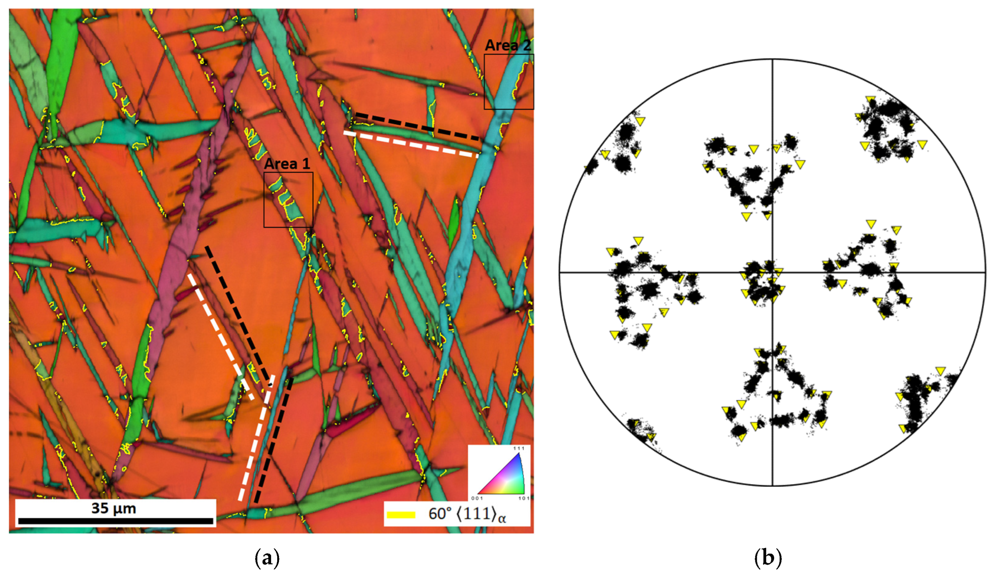
3.2. The OR and HP of Fully Grown Plates

Figure 1a shows a combination of an image quality (IQ) map and an inverse pole figure (IPF) map displaying martensite plates related to the same parent austenite grain. Figure 1b displays the experimental 110 α pole figure of the martensite shown in Figure 1a. The 110 α poles of the 24 possible variants of the Kurdjumov-Sachs OR that can theoretically form from the parent austenite grain are superimposed on the experimental pole figure as inverted yellow triangles. The good correspondence between the theoretical and the experimental orientations confirms that 225 γ martensite holds a near KS OR with austenite. As far the OR is concerned, solutions 1 and 3 cannot be distinguished while solutions 2 and 4 can be discarded. The white and black dotted lines in Figure 1a correspond to the traces of the HP for the variants of solutions 1 and 3, respectively. The HPs of solutions 1 and 3 are almost parallel, and there is good correspondence between both solutions and the corresponding austenite/martensite interfaces for the three plates selected. This analysis shows that the habit plane of martensite in the present alloy is closer to 112 γ , in agreement with the previous measurements [22]. The grain boundaries corresponding to a rotation of 60° around 111 α (with a tolerance of 5°) are highlighted in yellow in Figure 1a. Such boundaries are expected between two martensite crystals that are twin-related on the 112 α 111 α system. Two twinned areas, referred to as areas 1 and 2, are enclosed in black rectangles in Figure 1a. These areas are believed to correspond to the so-called transformation twins typically observed with TEM. This hypothesis is supported by the fact that the twinned areas are concentrated on only one austenite/martensite interface which is a characteristic feature of the 112 α transformation twins found in the substructure of 225 γ martensite [17,24].

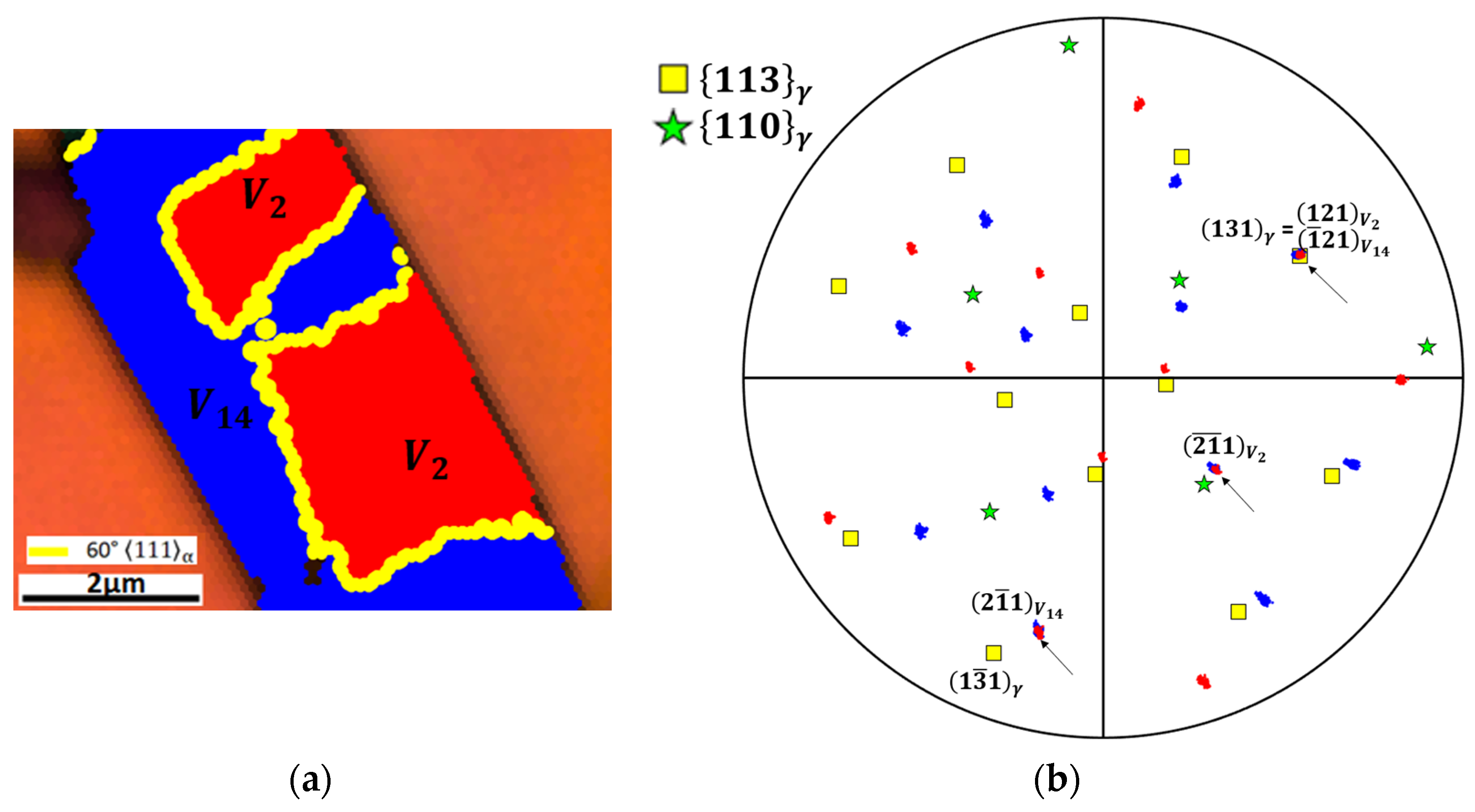
3.3. Local Misorientation Analysis at the Scale of the Transformation Twins

Figure 2a shows the IQ + IPF map of the area enclosed in area 1 in Figure 1a. Martensite pixels inside the matrix and twinned area are highlighted in blue and red, respectively. Misorientation calculations show that the twinned area is within 1° from the variant V 2 of the ORs of solutions 1 and 3, respectively. Similar calculations show that the matrix area is within 1.5° from the variant V 14 of the same ORs. Referring to Supplementary Material Table S1, if V 2 corresponds to solution 1, its correspondence variant (CV) is CV1 and its associated LIS is on ( 1 3 ¯ 1 ) γ [ 1 ¯ 01 ] γ ; meanwhile, if it corresponds to solution 3, it has the same CV1 but a different LIS on ( 131 ) γ [ 1 ¯ 01 ] γ . According to CV1, the ( 1 3 ¯ 1 ) γ and ( 131 ) γ planes originate from 21 ¯ 1 α and 121 α , respectively. Similarly, if V 14 corresponds to solution 1, it comes from CV3, and its LIS is on ( 1 3 ¯ 1 ) γ [ 1 ¯ 01 ] γ ; meanwhile, if it corresponds to solution 3, it has the same CV3 but a different LIS on ( 131 ) γ [ 1 ¯ 01 ] γ . According to CV3, the ( 1 3 ¯ 1 ) γ and ( 131 ) γ planes originate from 2 1 ¯ 1 α and 1 ¯ 21 α , respectively. It is then a priori possible to distinguish between solutions 1 and 3 by measuring the relative orientation of the ( 131 ) γ and ( 1 3 ¯ 1 ) γ planes with respect to the 112 α poles of variants V 2 and V 14 .
Figure 2b is the experimental 112 α pole figure of variants V 2 (red points) and V 14 (blue points) shown in Figure 2a. Three 112 α poles are in common between the two variants, as expected for crystal twin-related on the 112 α 111 α system. These poles are indicated by black arrows in Figure 2b. The 110 γ and 113 γ pole figures of the parent austenite are superimposed as yellow squares and green stars, respectively. It can be seen that none of the 110 γ poles are parallel to any of the three common 112 α poles. This tends to confirm that the LIS of 225 γ martensite does not correspond to a 110 γ 110 γ system. On the contrary, the ( 131 ) γ pole is strictly parallel to the common pole 121 V 2 / 1 ¯ 21 V 14 . Hence, a complete agreement with the experiments is obtained when considering that V 2 and V 14 are variants of the solution 3 of the PTMC with an LIS on ( 131 ) γ [ 1 ¯ 01 ] γ . In the Supplementary Material Figure S1, a second example corresponding to area 2 in Figure 1b is given and similar conclusions are reached. In all the other cases investigated, the high shear solution of the PTMC, solution 3, is perfectly consistent with the experiments. Referring to Supplementary Material Table S1, V 2 and V 14 have almost parallel habit planes of the form k h l ¯ γ , i.e., are close to 252 ¯ γ . It can be checked that this HP is at 25° from the 111 γ plane involved in the KS OR for V 2 and V 14 . This crystallographic feature is consistent with the previous studies on 225 γ martensite [16,17]. Moreover, the ( 131 ) γ plane, which is the plane of the LIS common to V 2 and V 14 , is nearly parallel to the habit plane of the macroscopic plate. This arrangement contrasts with the proposal made by Baur et al. in which the 112 α twinning plane of the LIS is at an angle of approximately 55° from the HP.

4. Discussion

The present EBSD analysis confirms that 225 γ martensite holds a near KS OR with the parent austenite as confirmed in Figure 1b. More importantly, most of the plates are composites consisting of two twin-related variants and both the matrix and the twin orientations hold a near KS OR with the surrounding austenite. Previous studies on the crystallography of 225 γ martensite considered these twins as transformation twins in accordance with the assumption that the LIS of this transformation occurs through twinning on the 112 α 111 α system [9,16,25]. The EBSD analysis demonstrates that none of the 110 γ austenite planes are parallel to any of the three common 112 α poles of the twin-related variants forming a macroscopic 225 γ plate. This simple observation invalidates the choice of the 110 γ 110 γ system as a viable LIS for the 225 γ transformation. Instead, most of the crystallographic features of 225 γ martensite are consistent with the predictions of the PTMC if the LIS occurs through slip on the 112 α 111 α system corresponding to a 113 γ 110 γ system in the austenite. Considering that the LIS occurs through slip rather than by twinning leads to a reinterpretation of the structure of 225 γ martensite. The twins observed in its substructure should not be regarded as the trace of the LIS, as in the original interpretation that was mostly influenced by the case of 3   10   15 γ martensite. Instead, they should be viewed as a distinct variant of the transformation, and macroscopic plates of 225 γ martensite should be considered as bivariant composite plates. In this interpretation, each plate is composed of two variants of the transformation that share the same LIS and almost the same habit plane, but that come from two different variants of the correspondence (different Bain strain). This interpretation is consistent with that of Baur et al. [16]. However, their theory requires an equibalanced fraction of twin and matrix orientations to achieve a 225 γ habit, which is not supported by our observations. The fraction of twin and matrix orientations in the fully grown 225 γ martensite plates shown in Figure 1a is systematically far from being equibalanced. In addition to its bivariant structure, another notable feature of 225 γ martensite is that its twins tend to concentrate on only one side of the austenite/martensite interface. This differs from 3   10   15 γ martensite in which the twins tend to concentrate along a central line known as the midrib, and hence, do not come into contact with parent austenite in fully grown plates. This dissimilarity may be due to the fact that in the case of 3   10   15 γ martensite, the matrix and the twin orientations hold very different ORs with the parent austenite. As previously explained by the present authors [26], the matrix orientation of 3   10   15 γ martensite in contact with the surrounding austenite, holds a near Nishiyama-Wasserman OR with compact planes and direction almost parallel in both phases. In contrast, the OR of the twin orientation only implies parallelism between the close-packed planes of both phases, while close-packed directions deviate from each other by more than 8°. The large misalignment between the compact directions of the two phases is believed to explain why the twins of 3   10   15 γ martensite are not in contact with the surrounding austenite. In contrast, in the case of 225 γ martensite, both the matrix and twin orientations can be found in contact with the austenite, since they both hold a near KS OR with it. Furthermore, as both orientations share the same OR with the austenite, there is no reason to distinguish between a matrix and a twin orientation, unlike in the case of 3   10   15 γ martensite. Regarding the habit plane, the present study confirms that it is closer to 112 γ than 225 γ in the present alloy. However, for the sake of consistency, this martensite will still be referred to as 225 γ martensite throughout the text. The calculations demonstrate that two solutions of the PTMC (solution 1 and 3 in Table 1) with an LIS on 113 γ 110 γ are consistent with the experimentally measured OR and the HP. These two solutions differ mainly in the direction and magnitude of the shape strain. The most precise experimental measurements report an average SD close to 0   0.66   0.75 ¯ γ for a plate with an HP close to 252 γ [19,22]. This measurement significantly deviates from the SD of solution 1, which is close to 11 ¯ 2 γ (see Table 1). On the other hand, in the case of solution 3, the SD of V 2 and V 14 , which have a HP close to 252 γ , are 0.65   0.08   0.75 ¯ γ and 0.75   0.08 ¯   0.65 ¯ γ , respectively (see Supplementary Material Table S1). Interestingly, the predicted direction of the shape strain is almost exactly a permutation of the indices of the direction observed experimentally. However, it is still unclear why the predicted SD is not precisely 0.08   0.65   0.75 ¯ γ for an HP close to 252 γ because complete agreement with experiments would be achieved if it was the case. The magnitude of solution 3 is more than five times greater than that of solution 1. To the authors’ knowledge, only solution 1 has already been published in the work of Sandvik and Wayman [21]. The high shear solution may have been discounted on strain energy grounds, as is typical with solutions involving a large shear magnitude [24]. Therefore, it is recognized that the present experimental observations cannot assess the validity of all predictions of solution 3, especially regarding the shape deformation. One first way to overcome this situation would be to directly measure the shape strain on martensite plates that cross a free surface. However, previous studies have shown that this measurement is difficult and prone to significant experimental variation [22]. Instead, two indirect methods are proposed to assess the validity of shape strain of the high shear solution. In the first method, it is proposed to check whether the predicted shape deformation can explain the origins of the bivariant twinned structure of 225 γ martensite. This bivariant twin structure shares striking similarities with the bivariant block structure found in dislocated lath martensite [5,27]. According to Qi et al.’s crystallographic analysis, the bivariant block structure is favoured because it minimizes the transformation strain [28]. Similarly, the bivariant twinned structure of 225 γ martensite is believed to result from a cooperative mechanism that aims to minimize the strain associated with the transformation. In order to test this hypothesis, the coupling factor between the two twin-related variants V 2 and V 14 that make up the macroscopic plate shown in Figure 2a can be calculated [29]. This factor evaluates the degree of accommodation of the transformation strain between two variants. It varies from −1 when the strains mutually compensate to +1 when the two shape strains are identical. This factor reads
η V 2 V 14 = T r a c e ε V 2   ε V 14 / T r a c e ε V 2   ε V 2 T r a c e ε V 14   ε V 14
where ε V i is the transformation strain of variant V i and reads [30]
ε V i = 1 / 2 F P F V 2 + F P F V 14 I
where I is the identity matrix, and F P F V 2 and F P F V 14 are the shape deformation matrices of variants V 2 and V 14 that are calculated from the PTMC to be
F P F V 2 = 0.4886 1.0289 0.4928 0.0577 1.1161 0.0556 0.4438 0.8931 1.4278 ,   F P F V 14 = 1.4278 0.8931 0.4438 0.0555 1.1161 0.0577 0.4928 1.0289 0.4886
The coupling factor is then found to be equal to η V 2 V 14 = 0.97 . The fact that the coupling factor is almost equal to −1 shows that the two shape strains of the twin-related variants that make up a macroscopic plate mutually compensate in an almost perfect manner. Therefore, assuming the shape deformation matrices associated with the high shear solution are correct; the origins of the bivariant structure of 225 γ martensite can be explained by the need to minimize the transformation strain, as is the case for lath martensite.
The second indirect method proposed to verify the consistency of the theory’s predictions regarding the shape deformation is based on the fact that this shape deformation is different for the two variants that compose a macroscopic plate, as shown above. This situation differs significantly from that of 3   10   15 γ martensite, for which the present authors have previously demonstrated that the matrix and twin orientations share exactly the same shape deformation. This subtle difference is expected to result in different behaviour for both types of martensite when the transformation occurs under stress assistance. The substructure of 3   10   15 γ martensite should remain essentially unaffected by the presence of external stress. The proportion of transformation twins in a plate that undergoes transformation under stress should remain constant compared to a plate that undergoes transformation under stress-free conditions. If the predictions of the high shear solutions are correct, then the substructure of 225 γ martensite is expected to be influenced by the action of external stress during the transformation. For instance, if the transformation of the same austenitic grain as in Figure 2 would have occurred under a uniaxial tensile stress along the first axis, only the formation of variant V 14 would have been favoured. Consequently, the macroscopic plates with the habit plane of V 14 (which is almost the same as that of V 2 ) would be expected to become monovariants without any twinned regions inside. Therefore, the study of the crystallography of a stress-assisted 225 γ martensite plate is believed to be a simple and direct way to assess the consistency of the crystallographic predictions of the high shear solution regarding the shape deformation.

5. Conclusions

The crystallographic analysis, conducted using EBSD on 225 γ martensite, led to to a new interpretation of the substructure of 225 γ . It is proposed that macroscopic plates are bivariant composites made up of two twin-related variants. The use of the 110 γ 110 γ twinning system as a viable LIS for the 225 γ transformation is invalidated by a crystallographic analysis at the austenite/martensite interface. Instead, the measurements are consistent with the hypothesis that the LIS of the transformation occurs through slip on the 113 γ 110 γ system rather than by twinning as is commonly accepted in the literature. If this hypothesis is correct, a simple explanation can be proposed for the sudden change in the habit plane of plate martensite in iron alloys from 225 γ to 3   10   15 γ with increasing carbon content. This change would result from the change of the LIS from 113 γ 110 γ to 110 γ 110 γ . The orientation relationship and habit planes of 225 γ martensite are in good agreement with the high shear solution of the PTMC with an LIS on the 113 γ 110 γ system. The bivariant twinned structure of 225 γ martensite is shown to result from the need to minimize the transformation strain, similar to the case of dislocated lath martensite.

Supplementary Materials

The following supporting information can be downloaded at https://www.mdpi.com/article/10.3390/cryst14030287/s1. Table S1: variant classification, habit plane (HP), shape deformation direction (SD), magnitude of shear (m) for solutions 1 and 3 of the PTMC with an LIS through slip 113 γ 110 γ ; Figure S1: (a) IQ + IPF map of area 2 in Figure 1a. The matrix and twin orientations are highlighted in blue and red, respectively, (b) 112 α pole figure of variants V 1 (red points) and V 13 (blue points) in Figure S1a together with the 110 γ and 113 γ of the parent austenite.

Author Contributions

Conceptualization, L.M. and S.G.; methodology, L.M.; software, L.M. and S.G.; data curation, L.M.; writing—original draft preparation, L.M.; writing—review and editing, L.M. and S.G. All authors have read and agreed to the published version of the manuscript.

Funding

This research received no external funding.

Data Availability Statement

The raw data supporting the conclusions of this article will be made available by the authors on request.

Acknowledgments

Matteo Caruso formerly at the CRM is acknowledged for providing the raw alloy and for fruitful discussions.

Conflicts of Interest

The authors declare no conflicts of interest.

References

  1. Raabe, D.; Sun, B.; Kwiatkowski Da Silva, A.; Gault, B.; Yen, H.-W.; Sedighiani, K.; Thoudden Sukumar, P.; Souza Filho, I.R.; Katnagallu, S.; Jägle, E.; et al. Current Challenges and Opportunities in Microstructure-Related Properties of Advanced High-Strength Steels. Met. Mater. Trans. A 2020, 51, 5517–5586. [Google Scholar] [CrossRef]
  2. Vermeij, T.; Mornout, C.J.A.; Rezazadeh, V.; Hoefnagels, J.P.M. Martensite Plasticity and Damage Competition in Dual-Phase Steel: A Micromechanical Experimental–Numerical Study. Acta Mater. 2023, 254, 119020. [Google Scholar] [CrossRef]
  3. Park, H.S.; Kwon, O.-H.; Baskin, J.S.; Barwick, B.; Zewail, A.H. Direct Observation of Martensitic Phase-Transformation Dynamics in Iron by 4D Single-Pulse Electron Microscopy. Nano Lett. 2009, 9, 3954–3962. [Google Scholar] [CrossRef] [PubMed]
  4. Shinohara, Y.; Hishida, M.; Tanaka, Y.; Inamura, T. Analysis of Thin-Plate Martensite Microstructure in Steel Focusing on Incompatibility and Its Visualization. Acta Mater. 2023, 259, 119275. [Google Scholar] [CrossRef]
  5. Shibata, A.; Miyamoto, G.; Morito, S.; Nakamura, A.; Moronaga, T.; Kitano, H.; Gutierrez-Urrutia, I.; Hara, T.; Tsuzaki, K. Substructure and Crystallography of Lath Martensite in As-Quenched Interstitial-Free Steel and Low-Carbon Steel. Acta Mater. 2023, 246, 118675. [Google Scholar] [CrossRef]
  6. Krauss, G.; Marder, A.R. The Morphology of Martensite in Iron Alloys. Metall. Trans. 1971, 2, 2343–2357. [Google Scholar] [CrossRef]
  7. Umemoto, M.; Yoshitake, E.; Tamura, I. The Morphology of Martensite in Fe-C, Fe-Ni-C and Fe-Cr-C Alloys. J. Mater. Sci. 1983, 18, 2893–2904. [Google Scholar] [CrossRef]
  8. Kelly, P.M.; Nutting, J.; Cottrell, A.H. The Martensite Transformation in Carbon Steels. Proc. R. Soc. Lond. Ser. A Math. Phys. Sci. 1997, 259, 45–58. [Google Scholar] [CrossRef]
  9. Bowles, J.S.; Mackenzie, J.K. The Crystallography of Martensite Transformations III. Face-Centred Cubic to Body-Centred Tetragonal Transformations. Acta Metall. 1954, 2, 224–234. [Google Scholar] [CrossRef]
  10. Wechsler, M.; Lieberman, D.; Read, T. The Martensite Transformation. Trans. AIME 1953, 197, 1503–1521. [Google Scholar]
  11. Krauklis, P.; Bowles, J.S. The Direct Measurement of Length Changes in the (225) Martensite Habit Plane. Acta Metall. 1969, 17, 997–1004. [Google Scholar] [CrossRef]
  12. Dunne, D.P.; Bowles, J.S. Measurement of the Shape Strain for the (225) and (259) Martensitic Transformations. Acta Metall. 1969, 17, 201–212. [Google Scholar] [CrossRef]
  13. Bowles, J.S.; Mackenzie, J.K. The Crystallography of the (225)F-Transformation in Steels. Acta Metall. 1962, 10, 625–636. [Google Scholar] [CrossRef]
  14. Ross, N.D.H.; Crocker, A.G. A Generalized Theory of Martensite Crystallography and Its Application to Transformations in Steels. Acta Metall. 1970, 18, 405–418. [Google Scholar] [CrossRef]
  15. Acton, A.F.; Bevis, M. A Generalised Martensite Crystallography Theory. Mater. Sci. Eng. 1969, 5, 19–29. [Google Scholar] [CrossRef]
  16. Dunne, D.P.; Wayman, C.M. The Crystallography of Ferrous Martensites. Met. Trans. 1971, 2, 2327–2341. [Google Scholar] [CrossRef]
  17. Baur, A.P.; Cayron, C.; Logé, R.E. {225}γ Habit Planes in Martensitic Steels: From the PTMC to a Continuous Model. Sci. Rep. 2017, 7, 40938. [Google Scholar] [CrossRef] [PubMed]
  18. Shimizu, K.; Oka, M.; Wayman, C.M. Transmission Electron Microscopy Studies of {225}f Martensite in an Fe-8%Cr-1%C Alloy. Acta Metall. 1971, 19, 1–6. [Google Scholar] [CrossRef]
  19. Sandvik, B.P.J.; Wayman, C.M. The Substructure of (252)f Martensite Formed in an Fe- 8Cr- 1 C Alloy. Metall. Trans. A 1983, 14, 2455–2468. [Google Scholar] [CrossRef]
  20. Morton, A.J.; Wayman, C.M. Theoretical and Experimental Aspects of the “(225)” Austenite-Martensite Transformation in Iron Alloys. Acta Metall. 1966, 14, 1567–1581. [Google Scholar] [CrossRef]
  21. Ahlers, M. On the Theory of “{225}” Martensite. Scr. Metall. 1968, 2, 529–534. [Google Scholar] [CrossRef]
  22. Sandvik, B.P.J.; Wayman, C.M. Some Crystallographic Characteristics of the (252)f Martensite Transformation in Fe-Alloys. Metall. Trans. A 1983, 14, 2469–2477. [Google Scholar] [CrossRef]
  23. Muddle, B.C.; Krauklis, P.; Bowles, J.S. The Shape Strain of the (225)F Martensite Transformation. Acta Metall. 1976, 24, 371–380. [Google Scholar] [CrossRef]
  24. Gu, X.-F.; Furuhara, T.; Zhang, W.-Z. PTCLaB: Free and Open-Source Software for Calculating Phase Transformation Crystallography. J. Appl. Crystallogr. 2016, 49, 1099–1106. [Google Scholar] [CrossRef]
  25. Xu, C.Q.; Cao, X.M.; Li, G.J. (225)A Martensite Transformation and Kurdjumow-Sachs Mechanism. MSF 2008, 575–578, 924–929. [Google Scholar]
  26. Malet, L.; Godet, S. On the Relation between Orientation Relationships Predicted by the Phenomenological Theory and Internal Twins in Plate Martensite. Scr. Mater. 2015, 102, 83–86. [Google Scholar] [CrossRef]
  27. Morito, S.; Tanaka, H.; Konishi, R.; Furuhara, T.; Maki, T. The Morphology and Crystallography of Lath Martensite in Fe-C Alloys. Acta Mater. 2003, 51, 1789–1799. [Google Scholar] [CrossRef]
  28. Qi, L.; Khachaturyan, A.G.; Morris, J.W. The Microstructure of Dislocated Martensitic Steel: Theory. Acta Mater. 2014, 76, 23–39. [Google Scholar] [CrossRef]
  29. Bate, P.; Hutchinson, B. The Effect of Elastic Interactions between Displacive Transformations on Textures in Steels. Acta Mater. 2000, 48, 3183–3192. [Google Scholar] [CrossRef]
  30. Kundu, S.; Bhadeshia, H.K.D.H. Crystallographic Texture and Intervening Transformations. Scr. Mater. 2007, 57, 869–872. [Google Scholar] [CrossRef]
Figure 1. (a) Combined image quality + IPF map showing martensite plates and (b) corresponding experimental 110 α pole figure (black dots) and theoretical 110 α pole figure (inverted yellow triangles).
Crystals 14 00287 g001
Figure 2. (a) IQ + IPF map of area 1 in Figure 1a. The matrix and twin orientations are highlighted in blue and red, respectively. (b) 112 α pole figure of variants V 2 (red points) and V 14 (blue points) in Figure 2a together with the 110 γ and 113 γ poles of the parent austenite.
Crystals 14 00287 g002
Table 1. Theoretical results of the Bowles and Mackenzie theory for the present alloy using an LIS on 113 γ 110 γ . (HP = habit plane, SD = shape strain direction, MSD = magnitude of the shape strain, CV = correspondence variant).
L I S : P 2 = ( 1 3 ¯ 1 ) γ [ 10 1 ¯ ] γ ,   CV = 1 1 ¯ 0 1 1 0 0 0 1
Sol. 1Sol. 2Sol. 3Sol. 4
HP 0.36   0.82   0.44 γ 0.75   0.58 ¯   0.31 ¯ γ 0.39   0.82 ¯   0.41 γ 0.43 ¯   0.52 ¯   0.73 γ
SD 0.38 ¯   0.39 ¯   0.84 ¯   γ 0.10 ¯   0.59 ¯   0.79   γ 0.65 ¯   0.08   0.75   γ 0.29   0.75   0.59   γ
OR1.3° from KS9.9° from KS1° from KS7.5° from KS
MSD 0.28 1.531.530.28
Disclaimer/Publisher’s Note: The statements, opinions and data contained in all publications are solely those of the individual author(s) and contributor(s) and not of MDPI and/or the editor(s). MDPI and/or the editor(s) disclaim responsibility for any injury to people or property resulting from any ideas, methods, instructions or products referred to in the content.

