Article

Manufacturing of Sapphire Crystals with Variable Shapes for Cryosurgical Applications

by
Irina N. Dolganova
1,*,
Arsen K. Zotov
1,2,
Sergey N. Rossolenko
1,
Irina A. Shikunova
1,
Sergey L. Shikunov
1,
Kirill B. Dolganov
2,
Kirill I. Zaytsev
2 and
Vladimir N. Kurlov
1
1
Osipyan Institute of Solid State Physics of the Russian Academy of Sciences, Chernogolovka 142432, Russia
2
Prokhorov General Physics Institute of the Russian Academy of Sciences, Moscow 119991, Russia
*
Author to whom correspondence should be addressed.
Crystals 2024, 14(4), 346; https://doi.org/10.3390/cryst14040346
Submission received: 18 March 2024 / Revised: 29 March 2024 / Accepted: 1 April 2024 / Published: 4 April 2024
(This article belongs to the Section Crystal Engineering)

Abstract

:
Consideration of sapphire shaped crystals as the material for manufacturing of medical instruments expands the opportunities of various approaches for diagnostics, exposure and treatment. Due to physical, mechanical and chemical properties of sapphire, as well as to its complex shape, such instruments are capable to demonstrate better performance for medical applications comparing to common tools. However, the manufacturing of high quality sapphire crystal with such geometry is still a complex issue, that usually requires application of various crystal growth techniques assisted with the automated weight control system. In this work, we consider one of such cases, that is the growth of a sapphire crystal, which can be applied for cryosurgery as an applicator due to a hollow-monolithic shape transition. Its hollow part can be filled with coolant in order to enable fast freezing of biological tissue during application. For this aim, it is of high importance to exclude the appearance of inclusions during the shape transition. To overcome this problem, we suggest using of noncapillary shaping (NCS) technique of crystal growth and study the weight signal measured during the manufacturing. We obtain the analytical description of the weight signal alteration that can be used as the program equation to control the crystal shape. We experimentally demonstrate the advantage of using such crystal for cryosurgery and obtaining faster ice-ball formation inside the model gelatin-based medium in comparison with the usage of the monolithic sapphire applicator of the same diameter. The demonstrated ability can be applied for future development of cryosurgical tools, while the analytical description of the weight signal could find its application for NCS manufacturing of sapphire crystals for other purposes.

1. Introduction

It is well known that sapphire combines the unique set of properties which makes this material to be suitable for rather wide medical applications [1,2,3]. First of all, it demonstrates biocompatibility and chemical inertness, that allows for the direct contact of sapphire windows and probes with biological tissues and liquids [4,5]. Outstanding mechanical properties, such as high hardness, enable the development of sapphire medical instruments and bone implants [6,7]. Transparency in visible and near infrared ranges provides an ability to light delivering to tissues, which has been recently used for the development of concepts of optically-based sapphire multimodal instruments for tissue ablation, resection, diagnosis and therapy [8,9]. Among such combinations with optical modalities, one should pay attention on fluorescence spectroscopy, spatially resolved diffuse reflection analysis, laser coagulation and photodynamic therapy. These methods can be either combined in a single sapphire instrument, or implemented separately in sapphire scalpels, needles, probes and applicators. For instance, sapphire tips and tapers are applied for dental therapy to cut the tissue more efficiently than bare fibers [10,11]. In general, sapphire fiber tips have strong advantages in laser surgical methods, since they form an ablation crater with a smooth edge, small carbonization layer and small thermal necrotic zone [12]. Next, sapphire capillary needles allow for performing interstitial laser therapy [9]. They host optical fibers inside thin channels and provide tissue exposure to ablative radiation. It helps to preserve fibers from the direct contact with tissue that often leads to fiber damaging during the treatment. In addition, such needles are reusable in contrast to disposable bare fiber. Sapphire scalpels and blades are commonly used in microsurgery [13], since they can feature ultra sharp cutting edge (∼100 nm) comparing to common metal ones (>1 μm). It yields low physical adhesion to tissues and low friction coefficient and results in decreasing of the penetration force and the destructive effects. Besides the listed advantages, we should mention an ability of sapphire instruments to withstand multiple cycles of sterilization and cleaning along with an ability to use them during MRI.
The implementation of these concepts is provided by the application of crystal growth techniques, which allow for manufacturing of sapphire shaped crystals [1,14,15,16]. It helps to solve a severe problem of making crystals with complex cross-section, when mechanical shaping is impeded by high hardness of the material [17]. For example, the edge-defined film-fed growth (EFG) technique [18], which implies melt rise through the capillary channels of the die, can be applied to produce sapphire with long and thin internal channels with diameters less than 500 μm [19]. EFG is commonly used for manufacturing of relatively thin cylindrical crystals, ribbons and waveguides. Thus produced crystals are suitable for placing optical fibers inside these channels to implement the delivering of optical radiation to tissue.
Oppositely, monolithic, tubular and hollow crystals with relatively large cross-section can be manufactured by the noncapillary shaping (NCS) technique [20]. This method uses a wettable die. However, in comparison with EFG technique, in NCS method there is no need of the melt lifting from the crucible to the top of the die by the capillary channels. Nevertheless, a negative external static pressure exists in the melt column as in EFG technique. The main feature of the NCS technique consists of the delivery of the melt to the growth interface through a noncapillary channel via a wettable die. The word “noncapillary” indicates here that the channel’s diameter is greater than the value of the capillary constant. The main reason of choosing NCS technique for specific cases is that it allows for pulling crystals with large cross-sections without bulk inhomogeneities, such as microvoids or gaseous and solid inclusions, which are common for EFG-manufactured large crystals [21] and for variable shaping technique (VST), which enables one to vary a configuration of a crystal cross-section during the crystallization process [22]. It was shown that the geometry of the die’s channels have the direct impact on the appearance of gas inclusions, caused by the presence of the intersecting melt flows above the die and thus appeared minimum-velocity regions in the melt meniscus [23]. In NCS technique, this problem is solved either by the combination of capillary and noncapillary channels of the die that helps to suppress the capillary flow or by using only the noncapillary feed [20].
Sapphire shaped crystals grown by the NCS technique can be applied for manufacturing of applicators for cryosurgery. This method applies cold-induced tissue damage for non-surgical removal of various lesions and neoplasms [24,25,26]. It has found its application for the treatment of renal [27], skin [28,29] prostate [30,31], breast cancer [32,33]. The main mechanisms of tissue damage are connected with formation of intracellular ice and the following tissue disruption and necrosis, osmotic injury, hypoxia, and cell apoptosis as well as inflammatory response [34]. Cryosurgery implies special instruments, i.e., cryoapplicators and probes for surface or percutaneous contact with tissue. They are based on Joule-Thomson effect and flow of high-pressure gas [35], or can be cooled down by circulating or stored coolant [36]. The fast cooling down of tissues below the cryonecrosis threshold (lies between −20 °C and −40 °C) is the key-factor for the efficient cryosurgery [37]. Therefore, high thermal conductivity of the material chosen for an applicator plays significant role. Due to this, common applicators are made of metals [38,39,40,41]. At the same time, sapphire features high thermal conductivity at cryogenic temperatures, that along with the mentioned properties makes it a favorable material for cryosurgery [42]. We have shown recently that submerged monolithic sapphire applicator exceeds the performance of the metal ones [42]. Particularly, it ensures higher rate of tissue freezing, higher ice-ball volume and lower temperatures. Finally, such applicators can be additionally assisted with optical monitoring [8], which allows to overcome one of the main problem of cryosurgery, that is the uncontrollable tissue damage [36,43,44].
The applicator filled with the coolant, or even circulated coolant, liquid nitrogen or another, can be applied for further improvement of the cryosurgery performance (see Figure 1a). This would help to maintain low temperature of the contact part of the applicator during the procedure, which leads to the formation of larger ice-ball volume and more efficient necrosis of deep tissues. However, it implies the hollow sapphire crystal with the cavity for coolant storage. In its turn, the crystal bottom should have high quality with the absence of inclusions, as well as the symmetric surface from the cavity side. These restrictions are aimed on the uniform and predictable temperature distribution on the contact surface.
NCS technique gives an opportunity to growth such crystals with variable shape, particularly, consisted of the tubular and monolithic parts [20]. To control the crystal shape and quality, the growth process is often accompanied by the use of the automated control system based on the crystal weight sensor [45,46]. In its turn, it needs a program equation of the weight signal, that is determined by the desired crystal shape, the form of the applied crucible and die, as well as the behaviour and shape of the melt meniscus. The detailed description of the weight signal for the process of growing monolithic cylindrical and tubular sapphire crystals can be found in ref. [47]. However, the transition between tubular and monolithic parts of the described crystal needs special attention. In this work, we focus on the development of the program weight equation for this particular stage, analysing the actually measured weight signal and the change of the meniscus shape. We demonstrate thus manufactured hollow crystal and its advantage for cryosurgery. In particular, during the experiment with gelatin-based sample medium, we compare the temperature inside the sample and ice-ball volume with those obtained by the use of rod-like sapphire applicator with the same dimensions. The results of this study can be used for the development of improved types of cryoapplicators, based on the suggested shape of sapphire crystal. At the same time, the obtained analytical equation of the weight signal would help to enhance the control of the growth process of large crystals with variable shape.

2. Materials and Methods

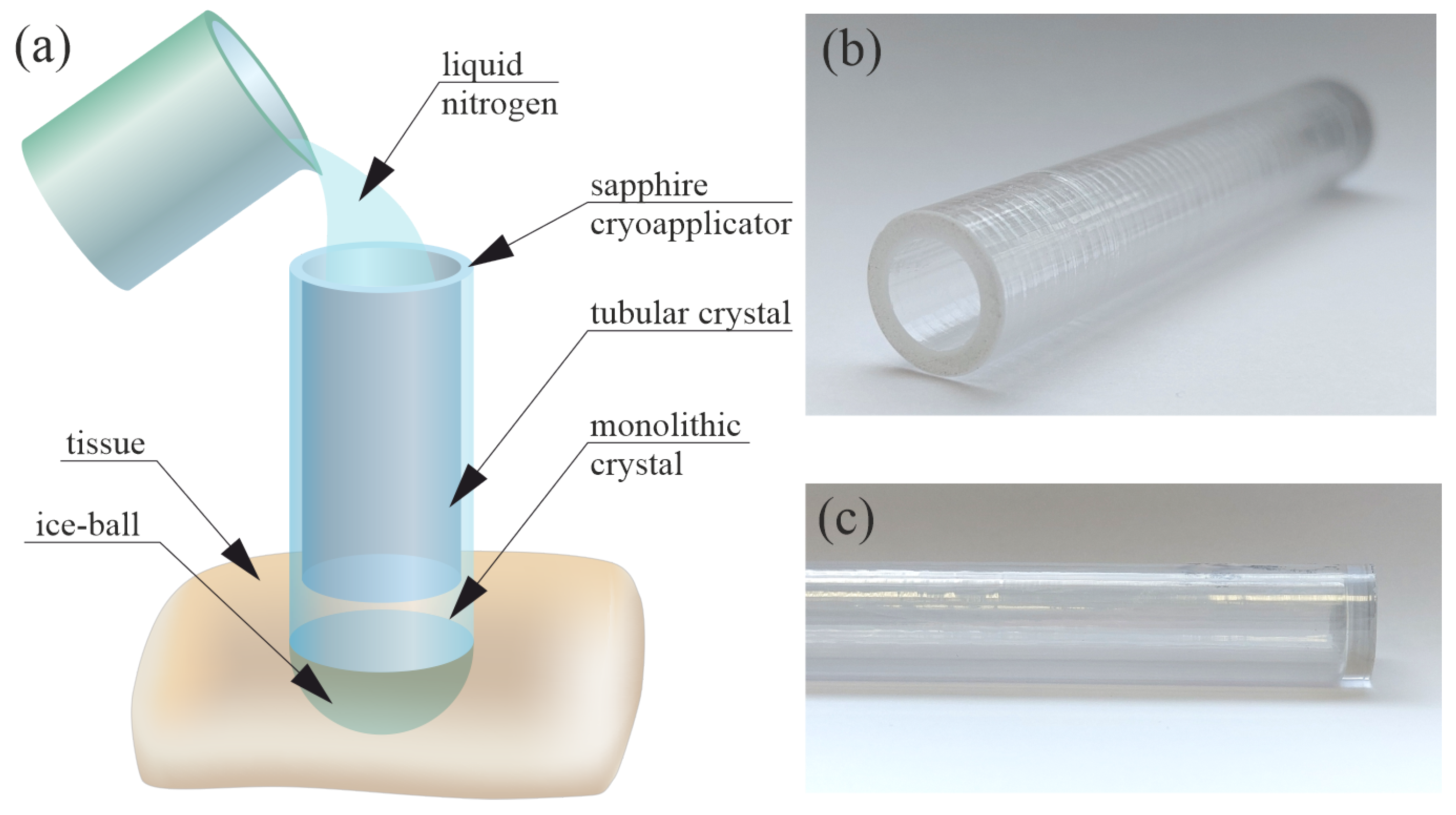
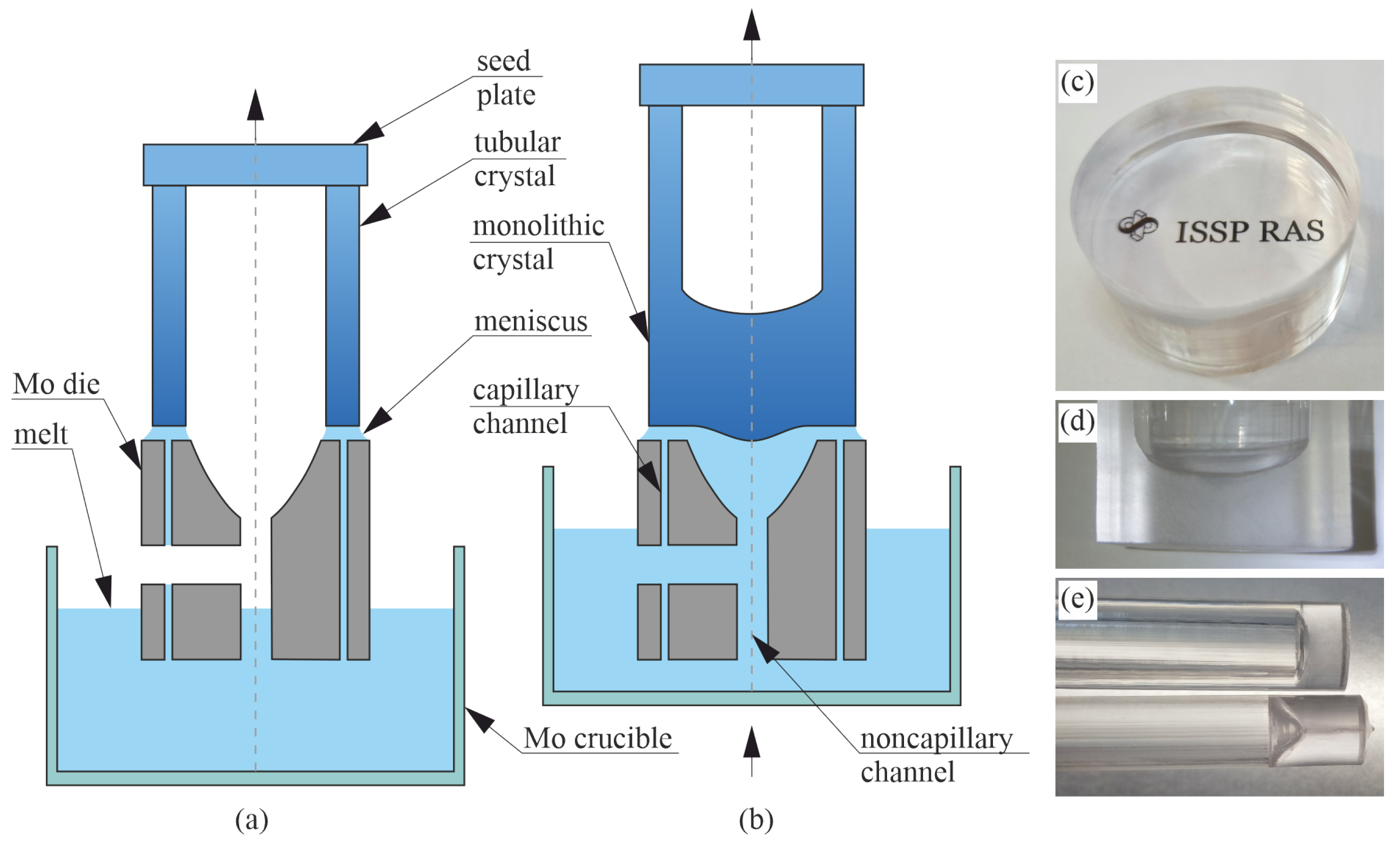
2.1. Manufacture of a Hollow Sapphire Crystal for Cryosurgery

In Figure 1, we demonstrate the principle of cryoapplicator for surface contact with tissue. It has the tubular and monolithic parts, both obtained during a single crystal growth cycle. The applicator is filled with liquid nitrogen; it results in cooling of the crystal and, therefore, in the formation of the ice-ball inside the tissue. The images of the crystal are shown in panels (b) and (c). The outer diameter is 12 mm, the length of the crystal is 10 cm, and the inner diameter is 8 mm.
To manufacture this hollow sapphire crystal, the commercially available growth setup NIKA (EZAN, Chernogolovka, Russia) was applied. It includes the growth chamber with a high-purity Ar atmosphere as an ambient, under a pressure of 1.1–1.3 atm, a molybdenum crucible with the 22 kHz induction-heated graphite susceptor, a die that has one or several channels for delivering the melt to the top of the die, which determines the cross-section of the grown crystal. The crushed Verneuil crystals (99.9999% Al2O3) were used as a charge material, while sapphire C-plane plate was used as a seed. The pulling rate was set to 30–50 mm/h.
The NCS technique makes it possible to grow hollow sapphire crystals with a controlled transition from the tubular part of the crystal to the monolithic one and vice versa. In this case, the die has a lateral noncapillary hole, which is located above the level of the melt in the crucible at the stage of the tubular crystal growth (Figure 2a). To change the cross-section from a tubular to a monolithic one, the crucible with the melt is raised to a position where the lateral hole of the die is completely immersed in the melt (Figure 2b). The closed volume below the seed begins to increase and the pressure decreases according to the Boyle–Mariotte law. The resulting difference in pressures forces the melt to rise inside the noncapillary section of the die. On further pulling, the melt arriving through the noncapillary section of the die joins the melt meniscus coming through the ring capillary channel, which results in the growth of a crystal with the shape of a solid rod. Figure 2c,d show the cross and longitudinal sections of a monolithic part of a high-quality sapphire crystal grown by the NCS method. Figure 2e shows hollow crystals grown by the VST technique (on the bottom) and by the NCS (on the top) method. The main advantage of the NCS method in comparison with VST is the absence of the gaseous and solid inclusions in the volume of monolithic part of the crystal. The photo of VST-grown crystal demonstrates the horizontal column of inclusions in the monolithic part.
The automated weight control system is applied during the growth process. It is based on the commercial calibrated weight crystal sensor (EZAN, Chernogolovka, Russia), which includes strain gauge that measures the weight within the range 0–5 kg with sensitivity 20 mg. The connection of strain gauge with computer is provided by the analogue-to-digital converter. Linearity of the weight measuring change was tested within the ranges of 0–100 g, 0–1 kg, 0–5 kg. The linearity was satisfactory in all ranges.
The measured weight signal M d (further referred as mass equivalent) is compared with the program (calculated) one; thus, the weight deviation is obtained. According to the lineal combination of the weight deviation and its first and second derivatives, the thermal zone heating power is changed. The heating power of the thermal zone directly affects the shape and the quality of the growing crystal. The linear combination of the weight deviation and its derivatives represents by itself the proportional-integral-differential (PID) procedure relatively to the dimension of the crystal cross-section, that is usually assumed as the radius R eq of the equivalent cylindrical rod crystal, since the first derivative (the proportional component of the PID law) is proportional to the deviation of the cross-section area, i.e., to the deviation of R eq 2 . Thus, to maintain the growth process, it is significant to analyze the deviation of the detected signal M d and the rate of change M ˙ d from the program equivalent mass and mass rate. While the program equivalent mass and mass rate for stationary growth of tubular and monolithic crystals are known [48], the transition stage in the case of NCS technique, including the melt rise through the noncapillary channel and tube closing, is of high interest. The detailed description of the weight signal is presented below.

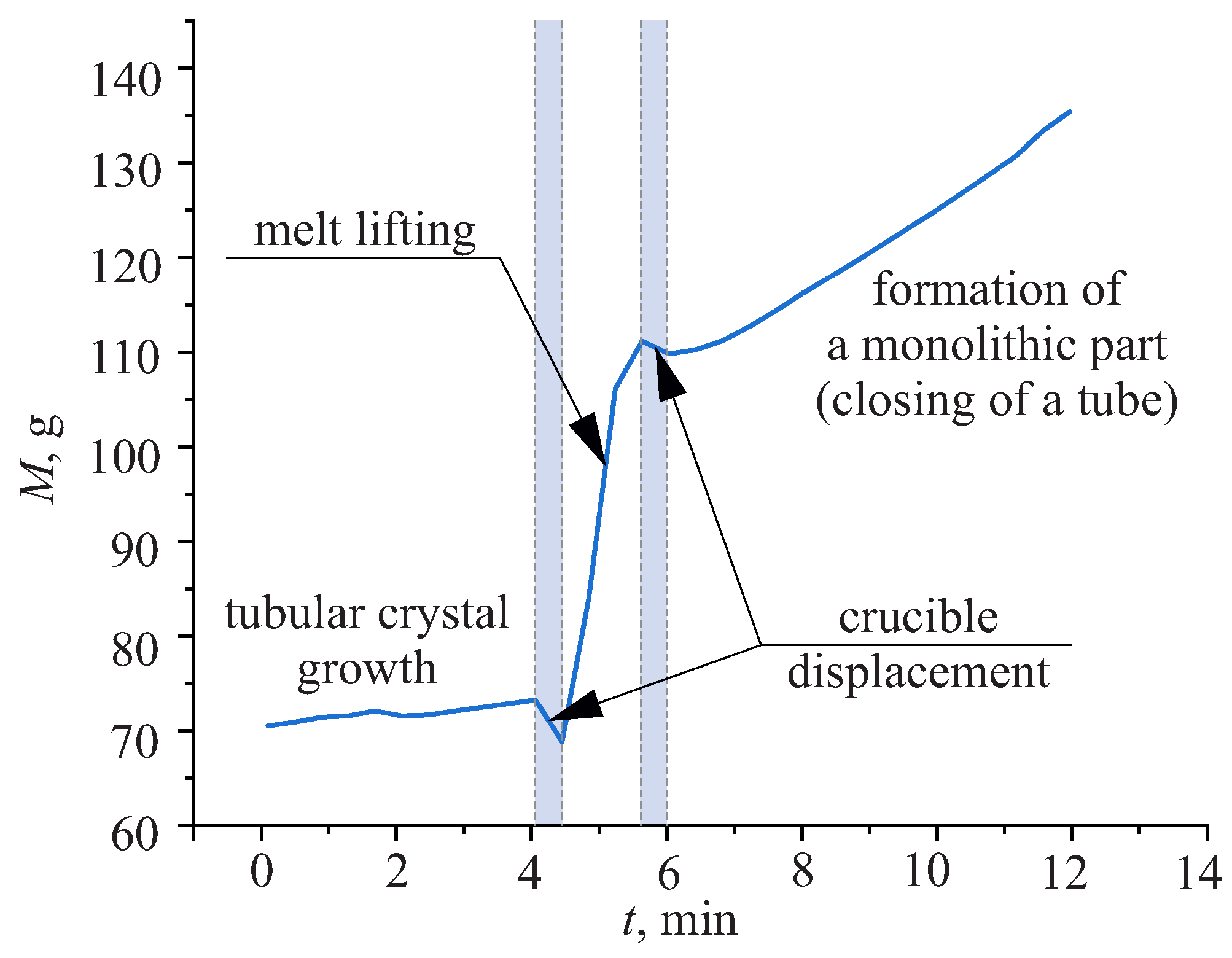
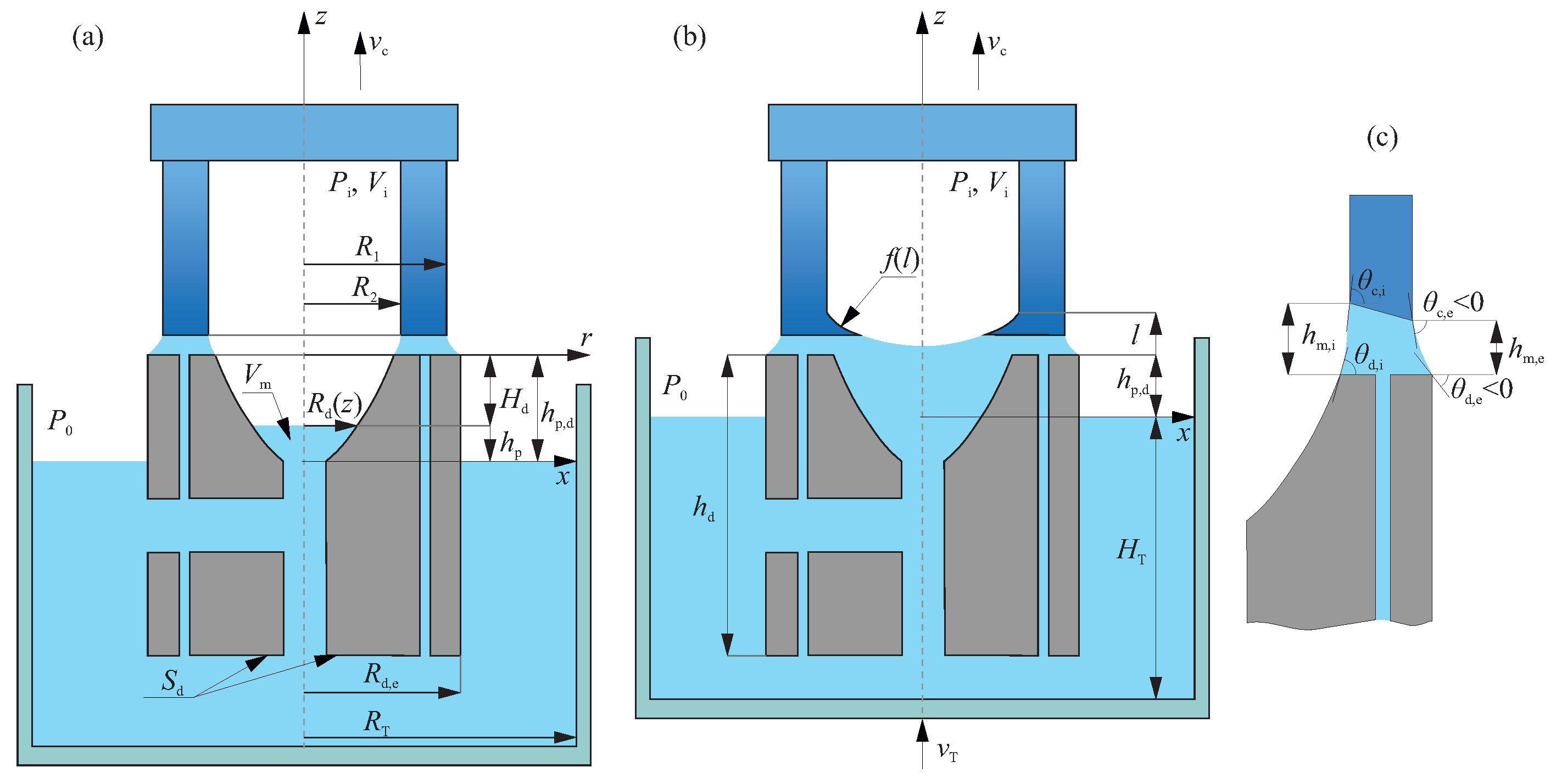
2.2. Mathematical Description of the Weight Signal

The schematic of the transition from tubular to monolithic crystal shape is shown in Figure 3. The stationary growth of a tubular part is characterized by the signal increasing. Then the crucible lifting leads to the decrease of the weight signal, that is mainly associated with the decrease in the modulus of the external static pressure in the meniscus caused by the reduce of the distance h p , d between the upper surface of the die and the melt level in the crucible. Then the melt lifting through the noncapillary channel results in the rapid increasing of the weight. Next, after the additional displacement of the crucible, which diminishes the signal, the formation of a monolithic part begins. In this work, we focus on the behaviour of the weight signal during the melt lifting and the closing of a tube since it determines the shape of the tube–rod interface.

2.2.1. The Stage of a Melt Lifting

For a quite long crystal tube, the temperature is changed along its length during the growth. However, for a fixed point ( r , z ) inside the tube and the melt volume that lifts through the noncapillary channel (Figure 3a), the temperature is almost independent of time. Thus, one can assume that the gas inside and near the tube is in isothermal conditions and the Boyle-Mariotte law is satisfied.
If P 0 is the initial pressure in the growth chamber before the process of a tube closing begins, V i , 0 is the initial volume of the gas inside the tube cavity, P i and V i are the corresponding parameters during the closing, the Boyle-Mariotte law defines
P 0 V i , 0 = P i V i .
The alteration of the gas volume V i is associated with the increment of the tube length, which increases V i , and at the same time with the inflow volume V m of the melt inside the noncapillary channel above the melt level in the crucible, that decreases V i ,
V i = V i , 0 + π R 2 2 t 0 t ν c d τ V m ,
V m = π 0 h p R d 2 ( z ) d z
where t 0 t ν c d τ = Δ l c ( t ) is the length increment of the tube with an outer radius R 1 and an inner radius R 2 ; ν c is the crystal pulling rate, R d ( z ) and h p stand for the current radius and height of the the melt level inside the noncapillary part of the die, respectively. We assume that the level of the melt flow in the noncapillary channel is flat. Thus, using Equation (1), we can find the current pressure P i inside the cavity above the lifting melt level
P i = P 0 V i , 0 / V i , 0 + π R 2 2 Δ l c ( t ) π 0 h p R d 2 ( z ) d z .
The difference between the pressure in the growth chamber outside the crystal P 0 and inside the tube P i is connected with the current height h p
P 0 P i = ρ L g h p ,
where ρ L is the melt density (‘L’ stands for liquid), g is the gravitational acceleration. Then, it is simple to deduce
h p = P 0 ρ L g 1 V i , 0 / V i , 0 + π R 2 2 Δ l c ( t ) π 0 h p R d 2 ( z ) d z ,
that is an integral equation for h p . It describes how the melt level in the noncapillary channel is connected with the shape of this channel and the pulling rate ν c .
Then, we consider the effective mass equivalent M d , detected by the automated weight control system
M d = M c + M m + M p ,
where M c is the mass of the crystalline tube, M m is the mass of the meniscus subjected to the negative external static pressure, M p is the mass equivalent due to the pressure of the melt with h p -height inside the noncapillary channel.
The current value of M c can be determined as
M c = ρ S 0 t ( R 1 2 R 2 2 ) ν c d t
where ρ S is the density of the crystal (‘S’ stands for solid).
M m depends on the current form of the meniscus (see Figure 3a,c)
M m = π ρ L ( R 1 2 R 2 2 ) ( h m , e + h m , i ) 2 π ρ L a 2 R 1 sin θ c , e + π ρ L a 2 R 2 sin θ c , i + π ρ L a 2 R d , e sin θ d , e π ρ L a 2 R d ( h p , d ) sin θ d , i π ρ L R d , e 2 R d 2 ( h p , d ) H d , H d < 0 , H d = h p h p , d ,
a is the capillary constant; h m , e , h m , i , θ c , e , θ c , i and R d , e are indicated in Figure 3. When the stationary growth of a tube is considered, angles θ c , e and θ c , i are equal to a constant value ε , that depends on the melt material. Finally, the third term in Equation (7) can be estimated as
M p = h p ρ L π R d 2 ( h p ) ,
which with Equation (6) gives
M p = π R d 2 ( h p ) P 0 g 1 V i , 0 / V i , 0 + π R 2 2 Δ l c ( t ) π 0 h p R d 2 ( z ) d z .
Thus, Equations (7)–(11) determine the weight signal during the melt lifting in the noncapillary channel before the tube starts to close.

2.2.2. The Stage of a Monolithic Part Formation

After the melt lifting and reaching the tube’s walls inside the cavity, the formation of the monolithic part of the crystal begins. It is accompanied with the partial crystallization of the melt near the walls (see Figure 3b). At the same time, liquid Al2O3 still exists in the central part of the tube. The overall process of a crystal shape transition is convenient to carry out using the rate of mass change M ˙ d as the parameter connected with the deviation of the crystal cross-section area.
At this stage, the detected mass calculated from the weight signal is the sum of the mass M c , that accounts the crystalline tube together with the crystallizing part near the walls, the equivalent mass M m of the meniscus, and the equivalent mass M p associated with the difference between the external and internal pressures of the tube. Thus, the rate of mass change M ˙ d , can be determined as
M ˙ d = M ˙ c + M ˙ m + M ˙ p .
The equivalent mass M p and its rate of change depend on the distance h p , d between the working edges of the die and the level of the melt in the crucible
M p = π ρ L h p , d f 2 ( l ) ,
M ˙ p = π ρ L h ˙ p , d f 2 ( l ) + 2 π ρ L h p , d f ( l ) f ( l ) z ν c
where f ( l ) is a function that describes the growing longitudinal section of the crystallizing part inside the tube, l is the length of the crystallizing part. To find h ˙ p , d , we use the concervation of mass
π ρ S R 1 2 f 2 ( l ) ν c = ρ L ( π R T 2 S d ) ( h ˙ p , d + ν T ) ,
S d is the area of the lower part of the die located in the melt, ν T is the speed of the crucible displacement, R T is the internal radius of the crucible. From Equation (15) we find
h ˙ p , d = π ρ S R 1 2 f 2 ( l ) ρ L ( π R T 2 S d ) ν c ν T .
Since the mass of the tubular part is constant at this stage, the rate M ˙ c accounts only the change of mass of the crystallizing part. Thus, it is written as follows:
M ˙ c = π ρ S R 1 2 f 2 ( l ) ν c .
The main contribution to the rate of change in the meniscus equivalent mass is due to the change in the external static pressure associated with the change in the melt level in the crucible. Therefore, the approximate expression for M ˙ m
M ˙ m π ρ L R d , e 2 f 2 ( l ) h ˙ p , d 2 π ρ L h p , d f ( l ) f ( l ) z ν c .
Finally, from Equations (12)–(18), we get
M ˙ d π ρ S R 1 2 f 2 ( l ) ν c + π ρ L R d , e 2 h ˙ p , d ,
where h ˙ p , d is estimated from Equation (16).
Thus, using Equation (19), one can implement the weight control of the crystal shape transition and maintain the desired geometry of the bottom that forms inside the crystal cavity.
To validate the obtained equations, we perform the following test. Using the thermal zone parameters and crystal growth regime, the program weight signal was calculated from Equations (7)–(11). Next, the weight signal during the melt lifting (see Figure 4) was measured without applying the automated control system (ACS) and describes the quasi-linear character of the weight alteration. The calculated weight signal matched exactly the measured one. Thus, the Equations (7)–(11) were approved and applied in ACS as the program equations. To verify the Equation (19), we assumed that during the formation of the monolithic part, the inner surface of the longitudinal crystal cross-section was described by the weakly parabolic curve. The real shape of the grown crystal surface was then compared with the assumed one. They were in good agreement; the error was less than 5%.

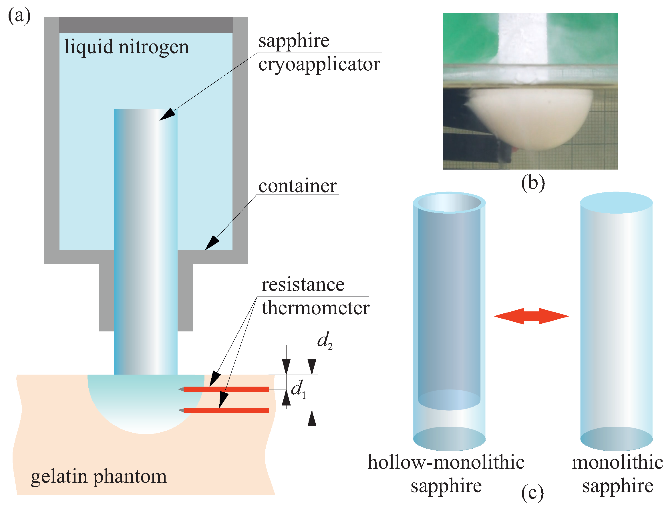
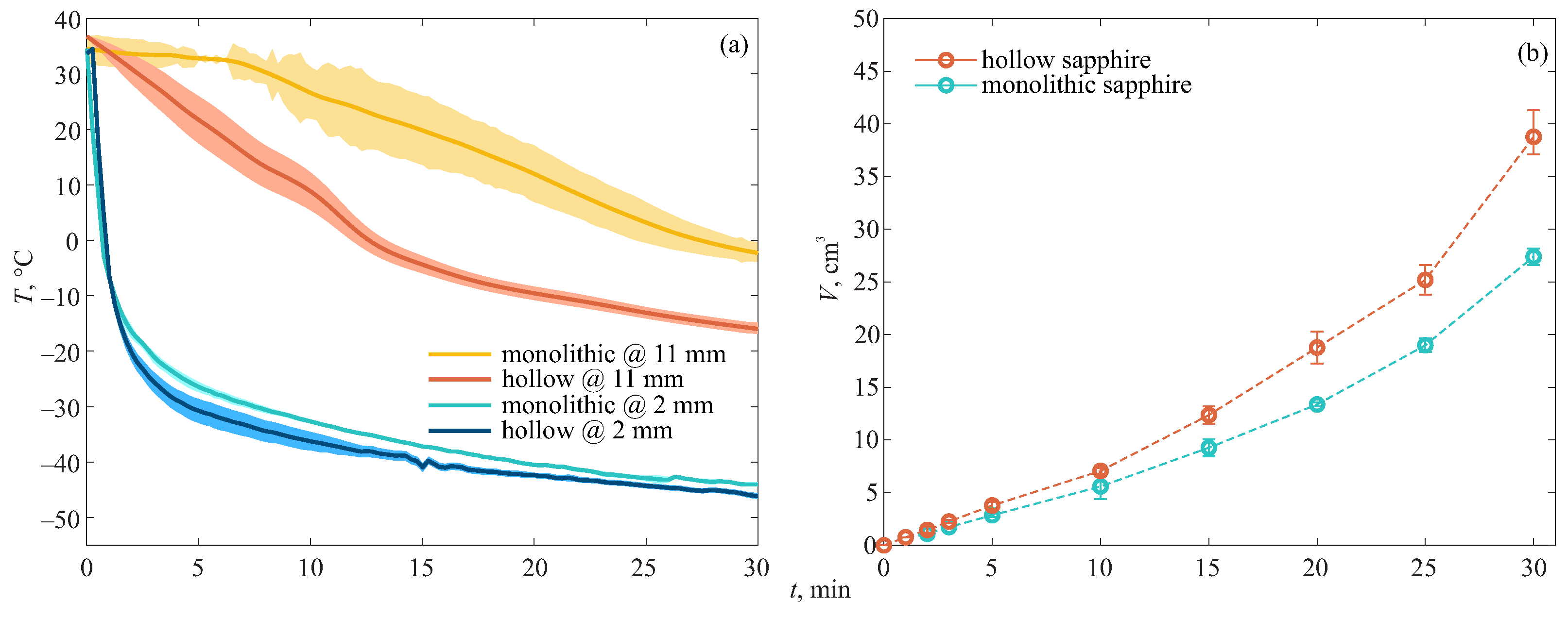
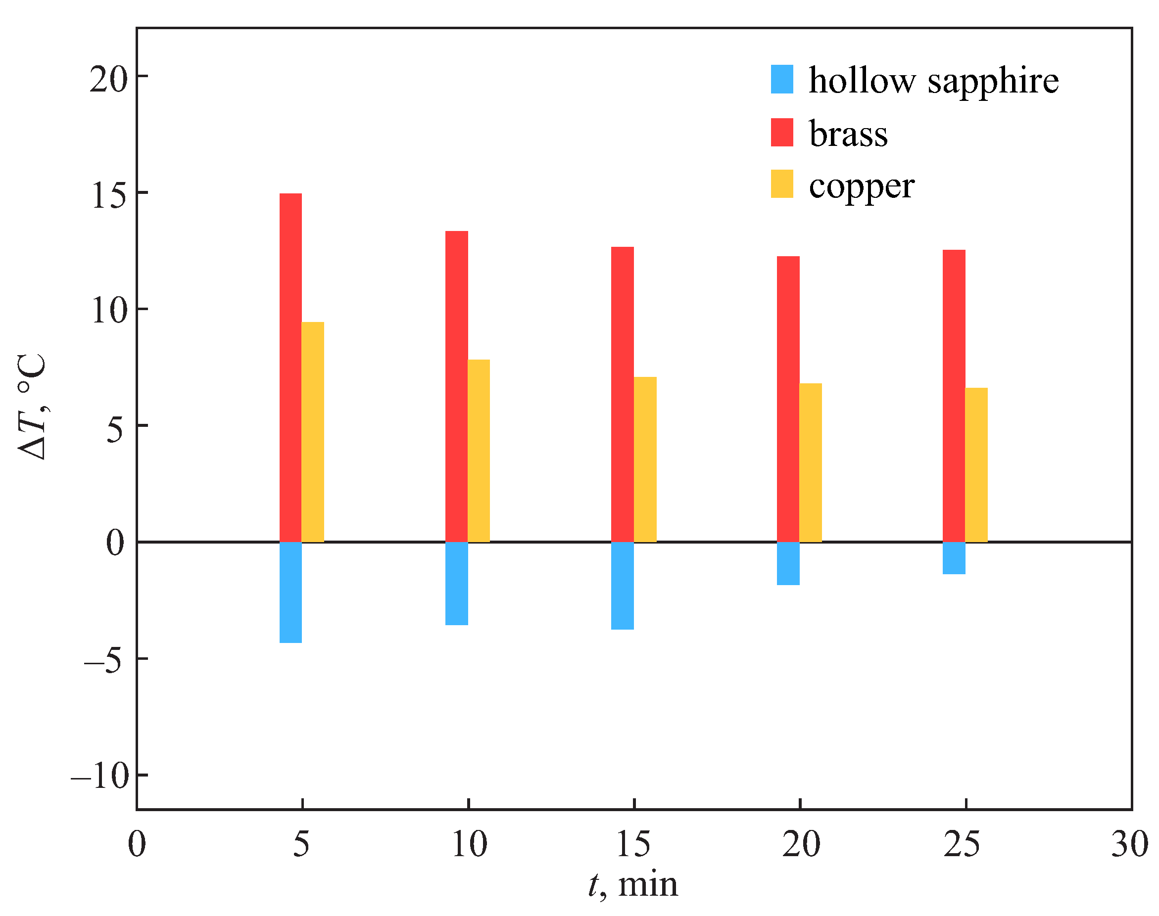
2.3. Study the Advances of Hollow Sapphire Applicator for Cryosurgery

To analyze the perspective of hollow sapphire crystal for cryosurgery, we compare its ability to form an ice-ball with sapphire cylindrical monolithic rod of the same length and outer diameter, also grown by the NCS technique. The experiment is schematically demonstrated in Figure 5. The test medium was made of gelatin aqueous solution with mass concentration 10 % and had the dimensions 105 × 105 × 105 cm3. The Table 1 shows the thermal properties of a 10% gelatin aqueous solution and some soft biological tissues at a temperature of 37 °C. It is obvious that gelatin phantom has specific heat capacity C p , thermal conductivity λ and thermal diffusivity α close to biological tissues. Also, the density ρ of the phantom is very close to real biological tissues. Thus, the gelatin solution quite accurately reproduces the thermal properties of biological tissues and can be used as a phantom for cryosurgery. The phantom was preheated up to 37 °C. The applicator was fixed in the isolated container, which then was filled with liquid nitrogen. Thus, before the contact with the sample, the applicator was cooled down to a constant temperature.
To study the ice-ball growth, the sample temperature was measured by two resistance thermometers (class B, OWEN, Moscow, Russia), which were fixed in the sample at d 1 = 2 and d 2 = 11 mm distance from the surface (see Figure 5a). The analysis of temperature helped to estimate the sample freezing rate.

3. Results

In Figure 6a we show the results of temperature measurement. It is clear that near the sapphire—sample interface, the temperature difference is small. But deeper in the sample, it becomes significant. It justifies the faster freezing of the tissue performed by the hollow sapphire applicator. From Figure 7, one can compare the performance of applicators made of different materials. Here Δ T = T i T ms is the difference between the sample temperatures at the depth 2 mm, measured for a specific applicator T i and the monolithic sapphire T ms . The data that represent the temperature difference between brass, copper and monolithic sapphire applicators were obtained for the jel-based tissue phantom (see ref. [42]), which has the thermal properties similar to living tissues [56]. In that study, the applicators were of the same size and were cooled down at the same conditions. The data for hollow and monolithic sapphire applicators were obtained from Figure 6a. It is clear that metal cryoapplicators demonstrate less effective tissue freezing than sapphire, both monolithic and hollow.
In addition, the ice-ball dimensions were analyzed using digital camera (Figure 6b) assuming the symmetry of the ice-ball. We should note that we exclude the alteration of the ice-ball shape due to the presence of the resistance thermometers. Since the sample cuvette has transparent walls, the actual dimensions are analyzed through the cuvette using scale bar. The results demonstrate the advantage of the hollow applicator to freeze larger volume. The difference is more obvious at the end of the process.
In cryosurgery, several cycles of freezing-thawing are commonly applied for obtaining of large volumes of cryonecrosis [57,58,59,60]. It is remarkable that replacement of monolithic applicator to a hollow one can lead to the same results. It could help to reduce the duration of the treatment.

4. Discussion

In this work, we demonstrate the concept of applying hollow sapphire cryoapplicator for more effective freezing of tissue, assuming cutaneous and superficial contact together with relatively large size of tissue lesions. The results show the increased rate of sample freezing and consequently the increased ice-ball volume. This would lead to more stable formation of cryonecrosis and complete removal of tissue lesion. It is important to stress that the possible incomplete tumor damage can lead to the occurrence of recurrent cancer [61]. The form of such applicator allows filling it with liquid coolant; therefore, the temperature near the contact part during the cryosurgery is lower comparing to monolithic applicators immersed in the coolant. Moreover, it opens the perspectives for implementation of coolant circulation, which would help to further reduce the temperature. The above mentioned results are prospective to possibly reduce the application duration and the number of freezing-thawing cycles for obtaining the same cryosurgical effect. In contrast to metal ones, the sapphire applicator can be included in the MRI-equipped operating room, which is extremely important for monitoring of ice-ball formation.
Despite the manufacturing of sapphire applicators is more expensive than metal ones and requires special equipment, they are reusable, withstand multiple sterilization and MRI-compatible. Nevertheless, they can be easily connected with the existing cryosurgical systems for superficial and percutaneous applications. However, it is obvious that the proposed concept can be hardly translated for the interstitial cryosurgery due to the size limit of NCS-manufactured crystals.
In the experimental part of this work, we used a simple gelatin sample, which gave us an opportunity to visualize the formation of an ice ball and perform temperature measurements. This phantom is reproducible and its properties are well-known. Since the present work is aimed at studying the feasibility of hollow sapphire applicator to be applied for cryosurgery and considers particular problems of crystal growth, we have left experiments with other media for further research work. In this regard, to more thoroughly study the difference between hollow and monolithic sapphire applicators, as well as compare their performance with that of metal applicators, more complex tissue-mimicking phantoms should be used along with the experiments with ex vivo and in vivo tissue specimens. It is important to assume the phantom that imitates the presence of vessels or tumors and to study the impact of blood circulations or moisture content. On the other hand, the impact of the crystal shape, in particular—the shape of the interface between tubular and monolithic parts, on the freezing rate and ice ball volume should be also investigated. In addition, comprehensive numerical simulation of heat transfer in various tissues during cryosurgery performed by sapphire applicator should be also considered in future studies.
The demonstrated sapphire applicator has cylindrical monolithic part. However, this part that serves as a contact tip can be subjected to additional mechanical processing. Thus, various shapes of the contact part can be obtained, which significantly expands the range of cryosurgical cases that can be solved. For instance, conical or rounded tip with rather small contact area can be obtained. In addition, as it is clear from Equation (19), the weight control can be applied for adjustment of the hollow-monolithic interface f ( l ) . Though the impact of different shapes of the monolithic part and interface on tissue freezing still needs to be studied separately, the possible variety of these shapes could help to increase the abilities of sapphire applicators. It should be highlighted that the applied NCS technique accompanied with the weight control leads to absence of gas inclusions that can be appeared due to the growth process. It enables the light delivering through the monolithic part and, thus, optical monitoring of the freezing process or additional tissue exposure to laser radiation.
Finally we should note that the proposed analytical description of the weight signal behaviour during the growth of hollow-monolithic crystal could be applied for manufacturing of crystals with rather wide variety of shapes. While sapphire rod with one hollow-monolithic transition of its shape can be applied as cryoapplicator, the crystal with two or more transitions can be manufactured.

5. Conclusions

In this work, the advantage of NCS technique for growing of the hollow-monolithic crystal is demonstrated for cryosurgical application. The weight control system assists the manufacture of such crystal that can be used as a cryoapplicator. It is aimed at formation of hollow-monolithic transition inside the crystal with absence of inclusions. We obtained the analytical description of the weight signal during the closing of tubular part of the crystal, which can be used as the program equation for controlling of the crystal shape.
The hollow crystal with thin monolithic part manufactured in the described way served as a cryoapplicator and filled with liquid coolant enables faster freezing of the sample and larger ice-ball volume formation in comparison with the monolithic sapphire rod of the same dimensions.
The concept of thus produced applicator is prospective for further development of cryosurgical methods, while the developed analytical description of the weight signal can be used for rather wide applications of NCS crystal growth technique.

Author Contributions

Conceptualization, I.N.D. and V.N.K.; methodology, S.N.R. and A.K.Z.; software, S.N.R.; formal analysis, K.I.Z.; experiment, A.K.Z. and I.A.S.; signal processing, A.K.Z. and K.B.D.; writing—original draft preparation, S.N.R. and S.L.S.; writing—review and editing, I.N.D. and V.N.K. All authors have read and agreed to the published version of the manuscript.

Funding

This work was supported by the Russian Science Foundation, Project # 19-79-10212.

Data Availability Statement

The data that support the findings of this study are available from the corresponding author upon reasonable request due to privacy.

Conflicts of Interest

The authors declare no conflicts of interest.

References

  1. Dobrovinskaya, E.R.; Lytvynov, L.A.; Pishchik, V. Sapphire: Material, Manufacturing, Applications; Springer: Boston, MA, USA, 2009. [Google Scholar] [CrossRef]
  2. Hutchens, T.C.; Darafsheh, A.; Fardad, A.; Antoszyk, A.N.; Ying, H.S.; Astratov, V.N.; Fried, N.M. Detachable microsphere scalpel tips for potential use in ophthalmic surgery with the erbium:YAG laser. J. Biomed. Opt. 2014, 19, 018003. [Google Scholar] [CrossRef] [PubMed]
  3. Polletto, T.J.; Ngo, A.K.; Tchapyjnikov, A.; Levin, K.; Tran, D.; Fried, N.M. Comparison of germanium oxide fibers with silica and sapphire fiber tips for transmission of erbium: YAG laser radiation. Lasers Surg. Med. 2006, 38, 787–791. [Google Scholar] [CrossRef] [PubMed]
  4. Qi, J.; Tatla, T.; Nissanka-Jayasuriya, E.; Yuan, A.Y.; Stoyanov, D.; Elson, D.S. Surgical polarimetric endoscopy for the detection of laryngeal cancer. Nat. Biomed. Eng. 2023, 7, 971–985. [Google Scholar] [CrossRef]
  5. Ramli, R.; Chung, C.C.; Fried, N.M.; Franco, N.; Hayman, M.H. Subsurface tissue lesions created using an Nd:YAG laser and a sapphire contact cooling probe. Lasers Surg. Med. 2004, 35, 392–396. [Google Scholar] [CrossRef] [PubMed]
  6. Zhou, Y.; Bian, H.; Song, X.; Lei, Y.; Sun, M.; Long, W.; Zhong, S.; Jia, L. Interfacial microstructure and mechanical properties of titanium/sapphire joints brazed with AuSn20 filler metal. Crystals 2022, 12, 1687. [Google Scholar] [CrossRef]
  7. Khalifa, A.A.; Bakr, H.M. Updates in biomaterials of bearing surfaces in total hip arthroplasty. Arthroplasty 2021, 3, 32. [Google Scholar] [CrossRef] [PubMed]
  8. Dolganova, I.N.; Zotov, A.K.; Safonova, L.P.; Aleksandrova, P.V.; Reshetov, I.V.; Zaytsev, K.I.; Tuchin, V.V.; Kurlov, V.N. Feasibility test of a sapphire cryoprobe with optical monitoring of tissue freezing. J. Biophotonics 2023, 16, e202200288. [Google Scholar] [CrossRef] [PubMed]
  9. Dolganova, I.N.; Shikunova, I.A.; Zotov, A.K.; Shchedrina, M.A.; Reshetov, I.V.; Zaytsev, K.I.; Tuchin, V.V.; Kurlov, V.N. Microfocusing sapphire capillary needle for laser surgery and therapy: Fabrication and characterization. J. Biophotonics 2020, 13, e202000164. [Google Scholar] [CrossRef] [PubMed]
  10. Stock, K.; Stegmayer, T.; Graser, R.; Förster, W.; Hibst, R. Comparison of different focusing fiber tips for improved oral diode laser surgery. Lasers Surg. Med. 2012, 44, 815–823. [Google Scholar] [CrossRef]
  11. Eguro, T.; Aoki, A.; Maeda, T.; Takasaki, A.A.; Hasegawa, M.; Ogawa, M.; Suzuki, T.; Yonemoto, K.; Ishikawa, I.; Izumi, Y.; et al. Energy output reduction and surface alteration of quartz and sapphire tips following Er:YAG laser contact irradiation for tooth enamel ablation. Lasers Surg. Med. 2009, 41, 595–604. [Google Scholar] [CrossRef]
  12. Bao, S.H.; Zheng, D.S.; Zhang, S.H.; Yu, G.R.; Lu, H.H.; Gai, B.K. Assessment of Nd:YAG laser via metal cap and sapphire tip delivery system: An experimental and clinical investigation. Chin. Med J. 1993, 106, 61–64. [Google Scholar] [PubMed]
  13. Ahmad, M.; Ismail, M. Effect of different shapes of recipient site creation micro-blades at varying angles and wound injury. J. Cosmet. Dermatol. 2021, 20, 3610–3615. [Google Scholar] [CrossRef]
  14. Tatartchenko, V.A. Shaped Crystal Growth. In Springer Handbook of Crystal Growth; Dhanaraj, G., Byrappa, K., Prasad, V., Dudley, M., Eds.; Springer: Berlin/Heidelberg, Germany, 2010; pp. 509–556. [Google Scholar] [CrossRef]
  15. Kurlov, V.N.; Rossolenko, S.N.; Abrosimov, N.V.; Lebbou, K. Shaped Crystal Growth. In Crystal Growth Processes Based on Capillarity: Czochralski, Floating Zone, Shaping and Crucible Techniques; Duffar, T., Ed.; John Wiley & Sons, Ltd.: Hoboken, NJ, USA, 2010; Chapter 5; pp. 277–354. [Google Scholar] [CrossRef]
  16. Akselrod, M.S.; Bruni, F.J. Modern trends in crystal growth and new applications of sapphire. J. Cryst. Growth 2012, 360, 134–145. [Google Scholar] [CrossRef]
  17. Gong, S.; Zhu, X.; Sun, Y.; Tang, B.; Su, Z. Experimental research on surface characteristics and subsurface damage behavior of monocrystal sapphire induced by helical micro abrasive tools. Ceram. Int. 2022, 48, 21459–21472. [Google Scholar] [CrossRef]
  18. LaBelle, H. EFG, the invention and application to sapphire growth. J. Cryst. Growth 1980, 50, 8–17. [Google Scholar] [CrossRef]
  19. Rossolenko, S.N.; Kurlov, V.N.; Asrian, A.A. Analysis of the profile curves of the menisci for the sapphire tubes growth by EFG (Stepanov) technique. Cryst. Res. Technol. 2009, 44, 689–700. [Google Scholar] [CrossRef]
  20. Kurlov, V. The noncapillary shaping (NCS) method: A new method of crystal growth. J. Cryst. Growth 1997, 179, 168–174. [Google Scholar] [CrossRef]
  21. Bunoiu, O.M.; Nicoara, I.; Santailler, J.L.; Theodore, F.; Duffar, T. On the void distribution and size in shaped sapphire crystals. Cryst. Res. Technol. 2005, 40, 852–859. [Google Scholar] [CrossRef]
  22. Borodin, V.A.; Steriopolo, T.A.; Tatarchenko, V.A. The variable shaping technique – a new method of the sapphire growth. Cryst. Res. Technol. 1985, 20, 833–836. [Google Scholar] [CrossRef]
  23. Borodin, V.A.; Steriopolo, T.A.; Tatarchenko, V.A.; Yalovets, T.N. Control over gas bubble distribution in shaped sapphire crystals. Cryst. Res. Technol. 1985, 20, 301–306. [Google Scholar] [CrossRef]
  24. Pasquali, P.; Mickeviciute, G. Cryosurgery. In European Handbook of Dermatological Treatments; Katsambas, A.D., Lotti, T.M., Dessinioti, C., D’Erme, A.M., Eds.; Springer International Publishing: Cham, Switzerland, 2023; pp. 1217–1228. [Google Scholar] [CrossRef]
  25. Gage, A.A.; Baust, J. Mechanisms of tissue injury in cryosurgery. Cryobiology 1998, 37, 171–186. [Google Scholar] [CrossRef] [PubMed]
  26. Korpan, N.N. (Ed.) Basics of Cryosurgery; Springer: Vienna, Austria, 2001. [Google Scholar]
  27. Deng, W.; Chen, L.; Wang, Y.; Liu, X.; Wang, G.; Liu, W.; Zhang, C.; Zhou, X.; Li, Y.; Fu, B. Cryoablation versus partial nephrectomy for clinical stage T1 renal masses: A systematic review and meta-analysis. J. Cancer 2019, 10, 1226. [Google Scholar] [CrossRef] [PubMed]
  28. Backman, E.; Polesie, S.; Berglund, S.; Gillstedt, M.; Sjöholm, A.; Modin, M.; Paoli, J. Curettage vs. cryosurgery for superficial basal cell carcinoma: A prospective, randomised and controlled trial. J. Eur. Acad. Dermatol. Venereol. 2022, 36, 1758–1765. [Google Scholar] [CrossRef] [PubMed]
  29. Pustinsky, I.; Dvornikov, A.; Kiva, E.; Chulkova, S.; Egorova, A.; Gladilina, I.; Peterson, S.; Lepkova, N.; Grishchenko, N.; Galaeva, Z.; et al. Cryosurgery for basal cell skin cancer of the head: 15 years of experience. Life 2023, 13, 2231. [Google Scholar] [CrossRef] [PubMed]
  30. Tan, W.P.; Chang, A.; Sze, C.; Polascik, T.J. Oncological and Functional Outcomes of Patients Undergoing Individualized Partial Gland Cryoablation of the Prostate: A Single-Institution Experience. J. Endourol. 2021, 35, 1290–1299. [Google Scholar] [CrossRef] [PubMed]
  31. Cohen, J.K.; Miller, R.J.; Ahmed, S.; Lotz, M.J.; Baust, J. Ten-Year Biochemical Disease Control for Patients with Prostate Cancer Treated with Cryosurgery as Primary Therapy. Urology 2008, 71, 515–518. [Google Scholar] [CrossRef] [PubMed]
  32. Mokbel, K.; Kodresko, A.; Ghazal, H.; Mokbel, R.; Trembley, J.; Jouhara, H. The Evolving Role of Cryosurgery in Breast Cancer Management: A Comprehensive Review. Cancers 2023, 15, 4272. [Google Scholar] [CrossRef]
  33. Kwong, A.; Co, M.; Fukuma, E. Prospective Clinical Trial on Expanding Indications for Cryosurgery for Early Breast Cancers. Clin. Breast Cancer 2023, 23, 363–368. [Google Scholar] [CrossRef]
  34. Baust, J.; Gage, A.; Bjerklund Johansen, T.; Baust, J. Mechanisms of cryoablation: Clinical consequences on malignant tumors. Cryobiology 2014, 68, 1–11. [Google Scholar] [CrossRef]
  35. Surtees, B.; Young, S.; Hu, Y.; Wang, G.; McChesney, E.; Kuroki, G.; Acree, P.; Thomas, S.; Blair, T.; Rastogi, S.; et al. Validation of a low-cost, carbon dioxide-based cryoablation system for percutaneous tumor ablation. PLoS ONE 2019, 14, e0207107. [Google Scholar] [CrossRef]
  36. Ward, R.C.; Lourenco, A.P.; Mainiero, M.B. Ultrasound-Guided Breast Cancer Cryoablation. Am. J. Roentgenol. 2019, 213, 716–722. [Google Scholar] [CrossRef] [PubMed]
  37. Velez, A.; DeMaio, A.; Sterman, D. Cryoablation and immunity in non-small cell lung cancer: A new era of cryo-immunotherapy. Front. Immunol. 2023, 14, 1203539. [Google Scholar] [CrossRef] [PubMed]
  38. Ranjbartehrani, P.; Etheridge, M.; Ramadhyani, S.; Natesan, H.; Bischof, J.; Shao, Q. Characterization of Miniature Probes for Cryosurgery, Thermal Ablation, and Irreversible Electroporation on Small Animals. Adv. Ther. 2022, 5, 2100212. [Google Scholar] [CrossRef]
  39. Goette, J.; Weimar, T.; Vosseler, M.; Raab, M.; Walle, U.; Czesla, M.; Doll, N. Freezing Equals Freezing? Performance of Two Cryoablation Devices in Concomitant Mitral Valve Repair. Thorac. Cardiovasc. Surg. 2016, 64, 672–678. [Google Scholar] [CrossRef] [PubMed]
  40. Steblyuk, A.N.; Gunter, V.E.; Khodorenko, V.N.; Bykova, E.V.; Avakimyan, R.A.; Geiko, I.A.; Dmitrieva, A.L. Results of chalazion cryosurgery with an increased risk of complications. Acta Biomed. Sci. 2021, 6, 181–189. (In Russian) [Google Scholar] [CrossRef]
  41. Gunjal, A.; Srivastava, A.; Atrey, M. Performance evaluation of liquid nitrogen-cooled cryoprobes using a combined numerical and experimental approach. Cryogenics 2023, 129, 103627. [Google Scholar] [CrossRef]
  42. Pushkarev, A.V.; Ryabikin, S.S.; Tsiganov, D.I.; Zotov, A.K.; Kurlov, V.N.; Dolganova, I.N. Comparison of Probe Materials for Tissue Cryoablation: Operational Properties of Metal and Sapphire Cryoprobes. J. Biomed. Photonics Eng. 2022, 8, 040501. [Google Scholar] [CrossRef]
  43. de Jager, N.S.; van Oostenbrugge, T.J.; Pätz, T.; Jenniskens, S.F.M.; Fütterer, J.J.; Langenhuijsen, J.F.; Overduin, C.G. Intraoperative MRI-derived volumetric ablation margins and initial correlation with local outcome after MRI-guided cryoablation of renal tumors. Cancer Imaging 2023, 23, 31. [Google Scholar] [CrossRef] [PubMed]
  44. Jankovic, I.; Poulsen, F.R.; Pedersen, C.B.; Kristensen, B.W.; Schytte, T.; Andersen, T.L.; Langhorn, L.; Graumann, O.; Krone, W.; Høilund-Carlsen, P.F.; et al. Preclinical cerebral cryoablation in non-tumor bearing pigs. Sci. Rep. 2022, 12, 1977. [Google Scholar] [CrossRef]
  45. Abrosimov, N.V.; Kurlov, V.N.; Rossolenko, S.N. Automated control of Czochralski and shaped crystal growth processes using weighing techniques. Prog. Cryst. Growth Charact. Mater. 2003, 46, 1–57. [Google Scholar] [CrossRef]
  46. Bruni, F.J. Control methodology for EFG sapphire crystals. J. Cryst. Growth 2022, 579, 126447. [Google Scholar] [CrossRef]
  47. Kurlov, V.; Rossolenko, S. Growth of shaped sapphire crystals using automated weight control. J. Cryst. Growth 1997, 173, 417–426. [Google Scholar] [CrossRef]
  48. Rossolenko, S. Menisci masses and weights in Stepanov (EFG) technique: Ribbon, rod, tube. J. Cryst. Growth 2001, 231, 306–315. [Google Scholar] [CrossRef]
  49. Pottathara, Y.B.; Jordan, M.; Gomboc, T.; Kamenik, B.; Vihar, B.; Kokol, V.; Zadravec, M. Solidification of Gelatine Hydrogels by Using a Cryoplatform and Its Validation through CFD Approaches. Gels 2022, 8, 368. [Google Scholar] [CrossRef] [PubMed]
  50. Yano, T.; Kong, J.Y.; Miyawaki, O.; Nakamura, K. The “Itrinsic” Thermal Conductivity of Wet Soy Protein and Its Use in Predicting the Effective Thermal Conductivity of Soybean Curd. J. Food Sci. 2006, 46, 1357–1361. [Google Scholar] [CrossRef]
  51. Popovic, M.; Minceva, M. Thermodynamic properties of human tissues. Therm. Sci. 2020, 24, 151. [Google Scholar] [CrossRef]
  52. Giering, K.; Minet, O.; Lamprecht, I.; Müller, G. Review of Thermal Properties of Biological Tissues. Proc. SPIE 1995, 25, 45–65. [Google Scholar]
  53. Mcintosh, R.L.; Anderson, V. A comprehensive tissue properties database provided for the thermal assessment of a human at rest. Biophys. Rev. Lett. 2010, 5, 129–151. [Google Scholar] [CrossRef]
  54. Xu, X.; Rioux, T.; Castellani, M. The specific heat of the human body is lower than previously believed: The Journal Temperature toolbox. Temperature 2022, 10, 1–5. [Google Scholar] [CrossRef]
  55. Patel, S.A.; Erickson, L.E. Estimation of heats of combustion of biomass from elemental analysis using available electron concepts. Biotechnol. Bioeng. 1981, 23, 2051–2067. [Google Scholar] [CrossRef]
  56. Agafonkina, I.V.; Belozerov, A.G.; Berezovsky, Y.M.; Korolev, I.A.; Pushkarev, A.V.; Tsiganov, D.I.; Shakurov, A.V.; Zherdev, A.A. Thermal Properties of Biological Tissue Gel-Phantoms in a Wide Low-Temperature Range. J. Eng. Phys. Thermophys. 2021, 94, 790–803. [Google Scholar] [CrossRef]
  57. Stewart, G.; Preketes, A.; Horton, M.; Ross, W.; Morris, D. Hepatic Cryotherapy: Double-Freeze Cycles Achieve Greater Hepatocellular Injury in Man. Cryobiology 1995, 32, 215–219. [Google Scholar] [CrossRef] [PubMed]
  58. Kwak, K.; Yu, B.; Lewandowski, R.J.; Kim, D.H. Recent progress in cryoablation cancer therapy and nanoparticles mediated cryoablation. Theranostics 2022, 12, 2175–2204. [Google Scholar] [CrossRef] [PubMed]
  59. Berth-Jones, J.; Bourke, J.; Eglitis, H.; Harper, C.; Kirk, P.; Pavord, S.; Rajapakse, R.; Weston, P.; Wiggins, T.; Hutchinson, P. Value of a second freeze-thaw cycle in cryotherapy of common warts. Br. J. Dermatol. 1994, 131, 883–886. [Google Scholar] [CrossRef]
  60. Baust, J.G.; Santucci, K.L.; Snyder, K.K.; Robilotto, A.; Baust, J.M. Mechanisms of Tissue Injury in Cryosurgery. In The Application of Heat in Oncology; John Wiley & Sons, Ltd.: Hoboken, NJ, USA, 2023; Chapter 4; pp. 45–71. [Google Scholar] [CrossRef]
  61. Sumari, S.N.; Mat Zin, N.A.; Wan Ismail, W.F.; Islam, M.A. Global Prevalence and Risk of Local Recurrence Following Cryosurgery of Giant Cell Tumour of Bone: A Meta-Analysis. Cancers 2022, 14, 3338. [Google Scholar] [CrossRef]
Figure 1. Hollow sapphire applicator for surface cryosurgery. (a) A schematic of the applicator and (b,c) images of the applied as-grown hollow crystal obtained by the NCS technique.
Crystals 14 00346 g001
Figure 2. The principle of NCS technique. (a,b) The schematic of growing tubular and monolithic parts of a crystal, respectively. (c,d) The cross and longitudinal sections of a monolithic part of a high-quality sapphire crystal grown by the NCS method. The label was printed on the paper lying under the crystal. (e) The hollow crystals grown by the VST (on the bottom) and NCS (on the top) techniques with diameters 16 and 18 mm, respectively.
Crystals 14 00346 g002
Figure 3. The schematic of the transition from hollow to monolithic crystal shape performed by the NCS technique. (a) Growth of the tubular part of the crystal during the melt rise through the noncapillary channel. (b) Transition to the monolithic part with closing of the tube. (c) The melt meniscus above the capillary channel.
Crystals 14 00346 g003
Figure 4. A mass equivalent calculated from a typical weight signal during the growth of a hollow tubular-monolithic crystal.
Crystals 14 00346 g004
Figure 5. Formation of an ice-ball by sapphire cryoapplicators. (a) Schematic of the experiment, where applicators, depicted in (c), with monolithic and hollow geometry are applied; (b) an example of an ice-ball formed in the gelatin medium.
Crystals 14 00346 g005
Figure 6. Analysis of an ice-ball formation in gelatin medium using hollow and monolithic sapphire applicators: (a) temperature measurements of the sample during freezing at the depths 2 and 11 mm; (b) estimated volume of an ice-ball grown in the sample. Error bars denote min-max range among three independent measurements.
Crystals 14 00346 g006
Figure 7. Comparison of the sample temperature at the depth 2 mm during freezing performed by different applicators. Δ T = T i T ms , where T ms is the sample temperature in case of using monolithic sapphire applicator, T i —in case of using monolithic copper, monolithic brass or hollow sapphire applicators. Measurement conditions are the same for each pair of applicators, for which a certain Δ T value was obtained. Data for metal applicators are from Ref. [42] and were obtained for a jel-based phantom.
Crystals 14 00346 g007
Table 1. Comparison of thermal properties of gelatin solution and soft tissues.
Tissue C p , J / ( g · K ) λ , W / ( m · K ) α , m 2 / s , 10 7 ρ , g / cm 3 References
Gelatin aqueous solution 10%3.800.5111.340.998[49,50]
Liver3.540.5661.501.050[51,52,53,54,55]
Brain3.620.5281.321.050[51,52,53,54,55]
Kidney3.760.5451.321.050[51,52,53,54,55]
Heart3.690.5871.481.060[51,52,53,54,55]
Disclaimer/Publisher’s Note: The statements, opinions and data contained in all publications are solely those of the individual author(s) and contributor(s) and not of MDPI and/or the editor(s). MDPI and/or the editor(s) disclaim responsibility for any injury to people or property resulting from any ideas, methods, instructions or products referred to in the content.

