Review

Ferroelectric Smectic Liquid Crystals

by
Atsushi Yoshizawa
Department of Frontier Materials Chemistry, Graduate School of Science and Technology, Hirosaki University, 3 Bunkyo-cho, Hirosaki 036-8561, Aomori, Japan
Crystals 2024, 14(4), 350; https://doi.org/10.3390/cryst14040350
Submission received: 18 March 2024 / Revised: 3 April 2024 / Accepted: 5 April 2024 / Published: 7 April 2024
(This article belongs to the Special Issue Dynamic Properties of Ferroelectric Liquid Crystals)

Abstract

:
Since the discovery of the first ferroelectric liquid crystal (FLC) in the chiral smectic C (SmC*) phase, ferroelectricity in liquid crystals has attracted much attention due to not only the fundamental interest but also the applications. This review focuses on the evolution of the design concept for ferroelectric smectic liquid crystals. It progresses from considering macroscopic phase symmetry to designing intermolecular interactions. For the purpose of understanding the molecular organization in smectic phases, we propose a dynamic model of constituent molecules in the smectic A (SmA) and SmC* phases based on 13C NMR studies. Then, we follow the structure–property relationship in ferroelectric SmC* liquid crystals for FLC displays. We reconsider de Vries-like materials that can provide defect-free alignment. We pay attention to the electro-optical switching in the chiral de Vries smectic A phase. Finally, we show several liquid crystals exhibiting polar smectic A phases and discuss how the polar order occurs in the highest symmetric smectic A phase.

1. Introduction

A ferroelectricity in liquid crystal was firstly reported to be observed in the chiral smectic C (SmC*) phase of DOBAMBC by Meyer et al. in 1975 [1]. Five years later, the bistable in-plane switching was demonstrated in a surface-stabilized ferroelectric liquid crystal (SSFLC) by Clark and Lagerwall [2]. Ferroelectric chiral smectic liquid crystals have been one of the most attractive research fields in liquid crystal science and technology [3,4,5,6,7]. Figure 1a shows polarization (P) as a function of an applied electric field (E) in the ferroelectric SmC* phase. The two stable states exist at E = 0 (also see Figure 1b). The phenomenon is called bistability. After an electric field is removed, each state is kept. It is called as a memory effect. When applying a triangular wave voltage, the polarization reversal current between the two states shows a single peak (Figure 1c). Ferroelectric liquid crystal displays (FLCDs) do not require a thin film transistor (TFT) in each pixel due to the memory effect. The switching speed between these two states driven by spontaneous polarization (Ps) is very high, with a response time of the µs order. The dark state is obtained when one of the polarizers is set parallel to the director, and the brightest state is obtained when the director is tilted with 45 degrees from each of the crossed polarizers (see Figure 2). The in-plane switching provides a wide viewing angle. They are very attractive for display applications. Canon manufactured the first 15-inch FLC panel with 1280 × 1024 pixels in 1995. However, the FLCDs could not replace TFT-LCDs based on nematic liquid crystals due to several reasons, such as the significant reduction in the manufacturing cost of TFT-LCDs and the difficulty in producing gray levels. On the other hand, Displaytech Inc. produced a 0.3-inch FLC microdisplay with VGA resolution, utilizing sequential color on each pixel, in 1997. Now, FLCDs are used in reflective microdisplays based on liquid crystal-on-silicon technology (LCOS) [8] for applications in 3D head-mounted displays and projectors.
During the development of FLC materials, an antiferroelectric liquid crystal MHPOBC was discovered by Chandani et al. in 1989 [9]. They observed the electric field-induced transition between the antiferroelectric chiral smectic C*A (Sm C*A) phase and the ferroelectric SmC* phase. A lot of research has been performed [10,11,12]. Figure 3a,b show the P-E curve in the antiferroelectric phase and the electric field-induced transition between the Sm C*A and SmC* phases, respectively. The P-E curve shows a double-hysteresis. P = 0 at E = 0 in the antiferroelectric state. As E increase, P shows a linear increase. Above a certain threshold, the antiferroelectric state changes to a ferroelectric state (Figure 3b). Two peaks in the switching current are observed corresponding to each transition (Figure 3c). Interestingly, Inui et al. reported a three-component mixture where the antiferroelectric–ferroelectric phase transition occurs continuously, without a threshold [13]. The V-shaped switching due to thresholdless antiferroelectricity has great advantages, such as a fast switching time, low driving voltage, high contrast ratio, and wide viewing angle, as well as being free from hysteresis [12].
Chirality had been believed to be necessary for the appearance of ferro- and antiferroelectricity since the report of the first FLC. Niori et al. discovered ferroelectric switching in a tilted smectic B2 phase of the achiral bent-core molecule P-n-O-PIMB in 1996 [14], and then Sekine et al. suggested chirality in the smectic B2 phase [15]. These findings opened new avenues for the study of polar order and chiral superstructures in liquid crystals [16,17,18,19,20]. Ferroelectricity was observed in a uniaxial smectic A phase of a bent-core molecule [21]. In 2017, two compounds, DIO [22,23] and RM734 [24], were reported to exhibit ferroelectric ordering in a nematic phase at low temperatures below the conventional nematic phase. The low-temperature N phase was assigned as the ferroelectric nematic phase (NF) [25,26]. Figure 4 shows a schematic image of the NF phase. The NF phase exhibits a huge spontaneous polarization and strong non-linear optical response. The ferroelectric molecular ordering in the nematic phase coupled with fluidity has not only fundamental significance but also great potential to revolute liquid crystal technologies [27]. DOMAMBC, MHPOBC, P-8-O-PIMB, RM734, and DIO (Figure 5) changed the liquid crystal world.
The purpose of this review is to demonstrate the evolution of the design concept for ferroelectric smectic liquid crystals: from considering macroscopic phase symmetry [1] to designing intermolecular interactions [21]. We describe structure–property relationships in ferroelectric smectic liquid crystals, focusing on the ferroelectricity and/or electro-optical switching in a uniaxial smectic A phase, which is the highest symmetrical smectic phase. We present the following topics: (1) a dynamic model for the molecular organization in smectic phases, (2) an electro-optical switching in the de Vries-like SmA phase, and (3) polar order in high symmetrical smectic A phases.

2. Ferroelectricity in Liquid Crystals

Let us describe how the ferroelectricity appears in the SmC* phase. According to Lagerwall [5], we apply Neumann’s principle to the N, SmA, SmC, and SmC* phases. Nematic LCs are described as differing from normal isotropic liquids only in the spontaneous orientation of the molecules, which are arranged with their long axes parallel to each other. Smectic A and C phases possess a layer structure, and the order inside the layer is liquid-like in these phases. In the SmA phase, though locally tilted, the average direction of the molecules is parallel to the layer normal. In the SmC phase, the molecules are tilted with respect to the layer normal, and the tilt direction is constant over considerable volume elements. In the SmC* phase, the molecules are tilted with respect to the layer normal and form a helical distribution when moving from layer to layer. The Neumann’s principle is described as follows: “the symmetry elements of an intrinsic property must include the symmetry elements in the medium”. The intrinsic property and the medium, here, are polarization and a liquid crystal phase, respectively. Figure 6 shows the phase symmetry of the N, SmA, and SmC phases. We assume that there is no distinction between the head and tail of the constituent molecule. In a nematic phase or smectic A phase, each medium is symmetrical by 180° rotation around the z-axis, corresponding to Px = −Px and Py = −Py. It is also symmetrical by 180° rotation around the y-axis, corresponding to Pz = −Pz. Therefore, Px = Py = Pz = 0; this means that the macroscopic polarization in a nematic phase or smectic A phase is zero. With respect to a smectic C phase that is a tilted biaxial phase, the medium is symmetrical by 180° rotation around the y-axis, corresponding to Px = −Px and Pz = −Pz. It has mirror symmetry about the x-z plane (Figure 7a); therefore, Py = −Py. The macroscopic polarization in a smectic C phase is zero. If the molecule is chiral, it does not overlap its mirror image (Figure 7b). The mirror symmetry does not exist. In that case, the smectic C phase transforms the chiral smectic C with a helical-layer structure. Local polarization in each layer exists; however, the helical arrangement makes the macroscopic polarization zero for the bulk state (Figure 8). A SmC* phase does not possess proper ferroelectricity.
Clark and Lagerwall demonstrated the macroscopic polarization for very thin samples of d ~1 µm [2]. Their design concept is as follows: “If the smectic layers are made perpendicular to the confining glass plates, there is no boundary condition compatible with the helical alignment. As the distance between the surfaces is shorter and shorter, the conflict between the helical order and the surface order will finally elastically unwind the helix via the surface forces. The helix cannot form below a certain sample thickness. It can be expected that the only allowed director positions will be where the surface cuts the smectic cone, because the intrinsic conical constraint and the constraint of the surface are simultaneously satisfied (Figure 9a) [5]”. The response of polarization to an applied electric field shows a characteristic ferroelectric hysteresis loop as shown in Figure 1a. They called this structure a surface-stabilized ferroelectric liquid crystal (SSFLC). The ferroelectricity in a helical SmC* phase is improper ferroelectric. The surface stabilization realizes a ferroelectric liquid crystal. The angle between the layer normal and the optical axis (n director) is defined as tilt angle θ (Figure 9b). The magnitude of polarization increases with the increase in the tilt angle. The sense of polarization is defined as shown in Figure 10. In a given compound, the sense of the helix and that of the spontaneous polarization are not necessarily related. How does the spontaneous polarization appear? The common statement for the origin of polarization is hindered rotation of a long molecular axis. However, two opposite experimental results have been reported for the rotation of the molecules around their long axis. A slowing down of the reorientation time around the long axis was detected by optical four-wave mixing experiments [28]. On the other hand, Kremer et al. reported that there is no change in the rotation at the SmA–SmC transition by using dielectric measurements [29]. On the contrary, Blinov and Beresnev noted that it is the directional bias for a lateral dipole of a molecule [30]. According to Lagerwall’s explanation [5]: “In the SmC* phase, the mirror symmetry is absent. A polar bias exists, which gives a different probability for the dipole to be directed at one side out of the tilt plane rather than in the opposite direction”.
Let us consider the design concept for the ferroelectricity in a nematic phase. Three curvature deformations, i.e., splay, twist, and bend, are allowed to exist in a nematic phase. A polarization may appear along the director in the case of splay (Figure 11a), while it may appear perpendicular to the director in the case of bend (Figure 11b). This polarization is called flexoelectric. The molecular organization is driven by the effect of the molecular shape, i.e., repulsive interactions. An appropriate molecular design is expected to induce macroscopic polarization in the nematic phase. However, it is difficult to simulate a polar nematic phase by using only repulsive interactions. Zannoni et al. developed a simple candidate structure that is non-centrosymmetric both in shape and in the attractive interactions of the two ends of the molecule for the computer simulation of a ferroelectric nematic phase [31]. They reported that a system of tapered particles endowed with a suitable directional attractive interaction can exhibit a phase sequence of isotropic liquid–apolar nematic–polar nematic phase–polar smectic. According to the simulation study, the molecular organization in the ferroelectric nematic phase is presented in Figure 12. The design concept can be applied not only to a polar nematic phase but also to a uniaxial polar smectic A phase.
The strain and stress effects on the ferroelectricity of thin films and crystals have been extensively investigated [32,33,34]. The effect of the strain on the generation of polarization has been theoretically treated in the piezoelectric phase of an FLC [5]. However, to the best of my knowledge, only a few experimental studies have been reported on the effects on ferroelectric liquid crystals [35,36]. Mathe et al. observed the first piezoelectric effects in two room-temperature ferroelectric nematic liquid crystal mixtures [36]. In my opinion, the flexoelectric polarization (Figure 11) may contribute to the effects. Further experiments are necessary to clarify the mechanism.

3. 13C NMR Studies on a Ferroelectric Liquid Crystal

In order to design smectic liquid-crystalline molecules, we have to know how the molecules organize in the smectic phases. We observed some ferroelectric and antiferroelectric liquid crystals by using solid-state 13C nuclear magnetic resonance (NMR) spectroscopy. The 13C NMR measurements give useful information on the microscopic environment and dynamics of each molecule in the liquid crystal phases. Let us introduce the NMR measurements of a ferroelectric liquid crystal MONBIC [37]. The molecular structure and phase-transition temperatures are shown in Figure 13. MONBIC exhibited a phase sequence of Iso–SmA–SmC*–Cry and showed a large spontaneous polarization value at about 100 nC cm−2 in the SmC* phase at 10 K below the SmA–SmC* transition.
Figure 14 shows the temperature dependence of the tilt angle determined by polarized optical microscopy (POM) or X-ray diffraction (XRD) measurements. The tilt angle determined by POM observation reflects the tilt of the core part with the delocalized electrons of the molecule. The layer spacings in the SmA and SmC phases were determined by XRD. A tilt angle is estimated by Equation (1),
cosθ = lC/lA
where lA is a layer spacing in the SmA phase, and lC is that in the SmC phase. The tilt angle determined by XRD reflects the average tilt of the molecule. The former shows larger tilt angles than the latter, indicating that the constituted molecules form a zigzag shape in the SmC* phase.
Figure 15 shows the 13C NMR spectra of MONBIC upon cooling from the isotropic liquid without sample-spinning. The 13C chemical shifts of the keto carbon (C23), the ester carbon (C18), and the aromatic carbons (C17, C16, and C20) increase markedly, but those of the other aliphatic carbons (C24, C9, and C1) decrease from the isotropic liquid to the SmA phase. These changes in the chemical shifts indicate that both of the core and the tails of the molecule tend to orient parallel to the magnetic field in the SmA phase. Upon cooling to the SmC* phase, those of the keto, ester, and aromatic carbons decrease on the contrary; furthermore, the marked line-broadening can be seen for those carbons. Those of the other aliphatic carbons also decrease slightly. These results provide useful information on the microscopic behavior of a single molecule in the smectic phases. The angle, with respect to the magnetic field of the core, increases in the SmC* phase as the temperature decreases, while that of the tail decreases slightly in the SmA and SmC* phases, as shown in Figure 16. The line-broadening for the core carbons is caused by the chemical shift anisotropy, which depends on the helicoidal structure in the SmC* phase. The core unit forms a helical structure (Figure 16).
We observed 13C spin–lattice relaxation times in the laboratory frame (T1) of MONBIC to know the dynamic behavior in the Iso, SmA, and SmC* phases. The molecular motions in the range from 10−12 to 10−8 s are effective in 13C T1. The temperature-dependent values for the tail carbon (C2), the asymmetric carbon (C24), and the core carbon (C12) are shown in Figure 17a. The continuous decrease in the T1 values reveals that the rotation around the long axis in the SmA and SmC* phases is almost the same as that in the isotropic liquid. The molecular motion of MONBIC in the smectic phases is liquid-like. It should be noted that the hindered rotation, which is often thought to be the origin of spontaneous polarization, was not detected in the SmC* phase. Figure 17b shows 13C spin–lattice relaxation times in the rotating frame (T1ρ) of an aromatic carbon (C21). The motions in the range from 10−6 to 10−4 s are effective in 13C T1ρ. 13C T1ρ values of the tail carbons were not detected. 13C T1ρ values of the core carbon (C21) are independent of temperature in each phase and show the discontinuous decrease at the SmA–SmC* transition, indicating that the cooperative molecular motion for the core part contributes to the layer ordering in each smectic phase, and the motion mode changes discontinuously at the SmA–SmC* transition. The collective motion in the SmA phase corresponds to the tilt fluctuations, and that in the SmC* phase corresponds to the molecular fluctuations around the cone.
Let us consider what happens at the phase transition. Figure 18 shows the temperature dependence of some protonated aromatic carbons. 13C T1 values of C12 decrease continuously at the SmA–SmC* transition, whereas 13C T1 values of C20 and C21 exhibit marked jump. Furthermore, 13C T1 values of unprotonated core and carbonyl carbons (C18 and C19) also show a significant jump at the transition. The analysis of those 13C T1 values reveals that the molecular deformation, such as a twist or bend for the core part, occurs at the transition (Figure 19).
The NMR studies reveal the dynamic behavior of molecules in the smectic phases: (1) cooperative motion detected for the core parts is responsible for the orientational order of the molecules in each layer; (2) interlayer permeation of tails causes the correlation between cores’ adjacent layers; and (3) conformation change occurs near the smectic A–chiral smectic C (or smectic C) transition. An illustration of the model is shown in Figure 20. The correlation of molecular motion between neighboring molecules considerably affects the long-range order in the smectic phases. Introducing a polar group into the core unit improves the Ps-driven switching speed. The design of the core–core interactions and the interlayer permeation produce various molecular organizations in the smectic phases.

4. Materials for Ferroelectric Liquid Crystal Displays

4.1. FLCs Exhibiting Large Spontaneous Polarization

Practical FLC mixtures consist of a host smectic C liquid crystal doped with a small amount of a chiral compound with large spontaneous polarization. The effects of the molecular structure on the magnitude of spontaneous polarization have been studied [38,39,40]. Lots of chiral smectic liquid crystals have been prepared and their physical properties investigated [41]. Some chiral dopants are presented in Figure 21.
Let us introduce some FLCs possessing a 2-methyalkanoyl group or a 2-fluro-2-methyalkanolyoxy group developed in Nippon Mining Co., Ltd., Tokyo, Japan. (later Japan Energy Corporation). Those chiral groups were derived from (R)-(+)-1,2-epoxyalkane. Figure 22 shows MOPBIC with a (S)-2methyloctanoly group [45]. The compound showed both ferroelectric and antiferroelectric phases. Its phase-transition temperatures were Iso 157 °C SmA 138 °C SmC* 81 °C SmC*A 64 °C unidentified smectic phase [46]. The spontaneous polarization was 112 nC cm−2 at TAC* −10 °C. For a perfectly ordered system, the magnitude of normalized polarization P0 (=Ps/sinθ) can be approximated by Equation (2),
P0~NA·(V·d/M)(1/Vµ = NA·d·µ/M
where NA is Avogadro constant, d is density, M is a molecular weight, µ is a dipole moment perpendicular to the long axis, and V is a unit volume. The dipole moment of the functional group adjacent to the asymmetric carbon contributes to the magnitude of Ps in the SmC* phase [39]. The perpendicular dipole moment (µ) of the keto group is calculated to be 1.99 D. Assuming a density of 0.8 g/cm3 for MOPBIC in the SmC* phase, the magnitude of P0 is estimated to be about 600 nC cm−2 at the first approximation. The magnitude of P0 calculated from that of Ps for MOPBIC is 313 nC cm−2 at TAC* −10 °C. Favorable dipole orientation in the SmC* phase is achieved.
Figure 23 shows a synthetic scheme of an FLC MFPYP possessing a 2-fluoro-2-methylheptanoyloxy group [47]. 2-Methylheptene was converted to (R)-2-methyl-1,2-epoxyheptane by using Norcardia corallina B-276. The epoxide was treated with hydrogen fluorine to give (S)-2-fluoro-2-methylheptanol. Then, it was oxidized with potassium manganate to the corresponding carboxylic acid. (S)-2-fluoro-2-methylheptanoic acid was treated with 2-(4-hexylpoxyphenyl)-5-(4-hydroxyphenyl)pyrimidine in the presence of N,N′-dicyclohexylcarbodiimide to give the target compound MFPYP. The compound showed a direct phase transition from the isotropic liquid to the SmC* phase at 130 °C. The magnitude of Ps at TAC* −2 °C was 250 nC cm−2. The compound shows favorable miscibility with a host smectic liquid crystal mixture consisting of phenylpyrimidine derivatives.
How is the polar order induced in an achiral host smectic LC by a chiral dopant? Lemuieux explained the chirality transfer in terms of chiral molecular recognition [40,48]. The collective effect of core–core interactions between a dopant with an axially chiral core and a host LC can propagate the chiral perturbations (Figure 24).

4.2. Host SmC Materials

Achiral smectic liquid crystals for the ferroelectric host mixture have been developed [49]. For manufacturing FLCDs, materials have to satisfy many important parameters, such as phase sequence, SmC* temperature range, spontaneous polarization, tilt angle, birefringence, dielectric anisotropy, rotational viscosity, elastic constant, N* pitch, and SmC* pitch. Their temperature dependence is also critical. For example, response time (τ) is expressed by Equation (3),
τ~η/(PE)
where Ps is spontaneous polarization, E is an electric field, and η is rotational viscosity.
In order to obtain a high switching speed, we have to decrease the rotational viscosity and increase spontaneous polarization. However, a compound with large Ps increases the rotational viscosity in its mixture. On the other hand, an SmC host LC is required to show a phase sequence of Iso–N–SmA–SmC to obtain a favorable molecular alignment. Phenylpyrimidine derivatives are used for the preparation of host SmC mixtures. They show an SmC phase with a relatively low viscosity. Figure 25 shows typical 2-ring and 3-ring phenylpyrimidine LCs.
A smectic C compound with a wide SmC temperature range and low viscosity is necessary for developing practical FLC mixtures. We designed 6-alkyl-2-(4-alkyloxyphenyl)quinoline (PQm,n) as a base SmC liquid crystal [50]. Compound PQm,n was prepared as shown in Figure 26. 4-Alkylaniline was converted to 6-alkylquinoline by the Skraup method [51]. It was treated with 4-methoxyphenyl lithium to give 6-alkyl-2-(methoxyphenyl)quinoline. The compound was deprotected with boron tribromide and then reacted with alkyliodide to give the target compound, PQm,n.
PQ8,6 exhibited a phase sequence of Iso 117 °C N 113 °C SmA 104 °C SmC 69 °C Cry. Compound PQ8,6 and 2-ring phenylpyrimidine derivative 8-PYP-6O shows continuous miscibility across the full composition range for the N, SmA, and SmC phases of both compounds. We prepared two FLC mixtures, i.e., mixture A (PQ8,6: 54 wt%/8-PYP-6O: 36%/chiral dopant: 10 wt%) and mixture B (8-PYP-6O: 90%/chiral dopant: 10 wt%). The chiral dopant used for the ferroelectric mixtures was (S)-4-(2-methyloctanoyl)-4′-biphenyl 3-chloro-4-octyloxybenzoate. Both mixtures showed a phase sequence of Iso-N*-SmA-SmC*. The SmA-SmC* transition temperature for mixture A was higher by 19 K than that for mixture B. Figure 27 shows the rotational viscosity, evaluated by switching studies, for mixtures A and B as a function of reciprocal temperature. The rotational viscosity for mixture A is similar to that for mixture B. PQm,n widens the SmC temperature range of a host LC consisting of 2-ring phenylpyrimidine derivatives without increasing the viscosity.
Difficult problems that are characteristic of a smectic C phase exist. A smectic layer thickness decreases as the temperature is lowered in the SmC phase due to the molecular tilt, which deforms the smectic layer structure from “a bookshelf structure” (Figure 28a) to “a chevron structure” (Figure 28b) [52,53,54]. The chevron structure reduces the effective switching angle to decrease the transmittance. If the rubbing direction is the same at both surfaces, there are two chevron structures, C1 and C2. In boundaries between the two different chevron structures, the smectic layers cannot fill the space, producing defects (Figure 28c).
Three approaches, i.e., pretilt, electric field, and materials, were performed to solve the problems [5]. We focus on the development of liquid crystals to provide a defect-free alignment. Mochizuki et al. reported naphthalene derivatives stabilizing a bookshelf-layer structure and demonstrated a defect-free prototype FLC display [55]. Janulis et al. reported a fluorinated phenylpyrimidine derivative exhibiting a weak negative layer expansion coefficient [56]. Their molecular structures are shown in Figure 29. The SmA layer spacing of the fluorinated compound increases with the increase in temperature. The layer spacing increases continuously through the SmA–SmC phase transition. Rieker and Janulis proposed a model in which steric interactions drive the antiparallel alignment of nearest neighbors in the SmA and SmC phases [57].
“De Vries-like” liquid-crystal materials are characterized by a maximum layer contraction of 1% upon transition from the SmA phase to the SmC phase [58]. De Vries proposed some diffuse cone models that describe the SmA phase in which mesogens have a tilted orientation and a random azimuthal distribution [59,60,61]. The de Vries SmA to SmC phase transition is described as an ordering of the azimuthal distribution; therefore, there is no change in the layer spacing at the phase transition. In de Vries I, the molecules are tilted in the same direction in each layer, while the azimuthal angle is disordered from layer to layer. In de Vries II, the molecules are tilted, but the azimuthal angle is disordered even in a single layer. According to the de Vries scenario, the layer spacing is kept constant, while the in-layer director tilts with respect to the layer normal from the SmA to SmC phase transition. The chiral version of this phase, termed de Vries SmA*, has attracted particular attention because of the absence of the zigzag defects as a consequence of associated minimal layer shrinkage across the SmA*–SmC* transition. Most of reported de Vries compounds consist of rod-like molecules with polysiloxane and polysilane terminal chains [62,63]. Recently, Kaur et al. reported unsymmetric bent-core molecules possessing de Vries-like properties [64]. Some typical compounds exhibiting de Vries-like properties are presented in Figure 30. The development of compounds exhibiting de Vries-like characteristics for improving FLCDs has to satisfy the following requirements: (1) good miscibility with a host SmC material and (2) no influence on the other physical properties of the FLC mixture.

5. Electro-Optical Switching in the De Vries Smectic A Phase

We reported an amphiphilic compound exhibiting the SmA–SmC phase transition without layer contraction [65]. The compound possesses a semiperfluorinated chain and a 2,3-difluoro-1,4-diphenylbenzene core (SFDPB), as shown in Figure 31. Figure 32 shows the layer spacings of SFDPB in the SmA and SmC phases as a function of the reduced temperature, TTAC. The layer spacing slightly increases as the temperature decreases, without layer contraction at the SmA–SmC transition, indicating that the SmA phase possesses a de Vries-like character. The de Vries SmA* phase has been reported to show an electro-optic response [58,62,66,67,68,69,70,71]. Compound SFDPB doped with 20 wt% of a ferroelectric liquid crystal, FLC-1 (see Figure 31), showed a phase sequence of Iso 159 °C Iso + chiral smectic A (SmA*) 145 °C SmA* 66 °C Cry and exhibited the electro-optical switching in the SmA* phase. The response times in the SmA* at 91 °C and 71 °C with an AC field of ±20 V cm−1 at a frequency of 10 Hz were 10 µs and 14 µs, respectively.
An external electric field induces a molecular tilt due to an electroclinic effect in an SmA* phase near the SmA*–SmC* transition. Garoff and Meyer found the electroclinic effect in which applying an electric field parallel to the layers of an SmA* phase induces a tilt with respect to the layer normal (Figure 33) [72]. The electric-induced tilt angle is described by Equation (4) [73],
θ = cE/{α(TTC)}
where c is the electroclinic coupling constant between θ and Ps, α is a nonchiral parameter known as the tilt-susceptibility coefficient, and TC is the Curie point corresponding to the second-order transition from the SmC* phase to the SmA* phase. As the temperature approaches TC, the tilt angle has a large value. The induced tilt angle is proportional to the strength of the applied electric field. Therefore, the resulting gray levels can be adjusted continuously.
We explain the SmA phase of SFDPB in terms of de Vries cone model. Figure 34 shows a model for the molecular organization in the SmA phase. The layer spacing at TTAC = −40 K was 44.47 Å. The extended molecular length of the amphiphilic compound is estimated to be 42 Å. The SmA phase might have a partially bilayered structure in which the molecules are tilted with respect to the layer normal. The observed electro-optical switching indicates that the SmA phase has an SmC-like ordering in each layer. The repulsion between the fluorinated chains in the interlayer regions decreases the correlation of the azimuthal distribution between adjacent layers. We surmise that SFDPB forms the SmA phase as the de Vries model I.
Karpernaum et al. reported a large electroclinic effect in the whole SmA* phase of a ferroelectric liquid crystal possessing a de Vries character [69]. Prasad et al. proposed an antiferroelectric-like ordering to explain the double-peak polarization current in the de Vries SmA* phase of systems in which a molecule contains siloxane and hydrocarbon chains [70]. Ghosh et al. supported the antiferroelectric-like model based on their observation of the double-peak current in the de Vries SmA* phase of a fluorinated antiferroelectric liquid crystal [71].
Figure 35 shows an illustration of the electro-optical switching in the de Vries-like SmA* phase of SFDPB doped with FLC-1. When E = 0, the molecules tilt in the same direction in each layer, while the azimuthal angle is disordered from layer to layer (de Vries I). The director is parallel to the layer normal. When applying an electric field, all the molecules reoriented along the direction of the electric field. This produces electro-optical switching between black and bright states.
According to the NMR studies, we surmise that increasing the core–core interactions and decreasing the interlayer interactions produce a de Vries I-type phase. We designed a chiral liquid-crystal trimer, MOHBC (Figure 36), and found that it exhibits an optically uniaxial smectic phase with a double-peak polarization [74]. The chiral trimer, MOHBC, exhibited two SmA* phases, i.e., the high-temperature SmA* (SmA*-H) phase and the low-temperature SmA* (SmA*-L) phase, and showed a phase sequence of Iso–SmA*-H–SmA*-L–SmC*–Cry upon cooling. Figure 37 presents optical textures in the SmA*-L phase of MOHBC with or without an electric field. The extinction direction was rotated counterclockwise with +E, but it was rotated clockwise with −E. Applying an electric field causes a distinct change in the interference color from yellow to red, related to the increasing birefringence. The increase in birefringence reveals that the orientation of the molecules without E is more disordered than that with E, suggesting that the SmA*-L phase has a de Vries-like character. Figure 38 shows the temperature dependence of the electrical response in the switching current under triangular waves. No switching current was detected in the SmA*-H phase (Figure 38a). The double-peak polarization current per half-period of the switching voltage appeared at TTIA* = −4.5 K in the SmA*-L phase, and it became larger with the decreasing temperature (Figure 38b,c). After further cooling, in addition to the double peaks, a single sharp peak characteristic of ferroelectric switching appeared in the SmA*-L close to the SmA*-L–SmC* transition (Figure 38d). Therefore, the SmA*-H phase is a chiral version of a conventional paraelectric SmA phase, whereas the SmA*-L phase exhibits antiferroelectric-like switching.
Figure 39 shows a binary phase diagram for mixtures of MOHBC with its enantiomer. The SmA*-L phase is replaced with the SmC* phase with decreasing optical purity, suggesting that the SmA*-L phase has an SmC-like layer structure. The double-peak polarization in the SmA*-L phase results from the electric field-induced antiferroelectric–ferroelectric transition. The SmA*-L phase structure is not antiferroelectric molecular ordering but the de Vries model I-like layer structure, as shown in Figure 40. The strong dipole moment due to the two ester units exists along the long axis, and the dipole–dipole interaction can cause the antiparallel alignment of adjacent molecules within each layer. The terminal cores have an in-layer anticlinic orientation, which disturbs an effective interlayer interaction. Furthermore, the chirality destabilizes the formation of the helical SmC* phase, as shown in Figure 39. Therefore, the chirality disturbs the interlayer twist interaction. Chirality and the hockey stick-like oligomeric structure induce the randomization of the azimuthal angle from layer to layer. Applying an electric field to the SmA*-L phase transforms it from the de Vries-like state to the ferroelectric state. These findings indicate that the origin of the electro-optical switching in the SmA phase of SFDPB doped with FLC-1 is explained in terms of the molecular reorientation around the core.
Design of de Vries chiral smectic liquid crystals for device applications has been performed [75,76]. The electro-optical switching in de Vries SmA* phase has great potential for applications of display: (1) it has a fast switching speed, (2) it shows an in-plane switching with wide viewing angle, (3) it produces gray levels continuously, and (4) it provides a defect-free alignment. The randomization of the azimuthal distribution in the de Vries phase can decrease the threshold voltage. Furthermore, the experience in FLC development can be utilized to optimize the physical properties of de Vries SmA* materials.

6. Polar Order in an Optically Uniaxial Smectic A Phase

The molecular design for a polar liquid crystal has attracted considerable interest. The macroscopic polarization density, characteristic of ferroelectric phases, is stabilized by dipolar interactions. These interactions are weakened as phases become more fluid and have higher symmetry, which limits the ferroelectricity of the biaxial smectic liquid crystals. Since the discovery of DOBAMBC, lots of chiral ferroelectric liquid crystals have been prepared. Achiral bent-core liquid crystals exhibit ferro- and antiferroelectricity in their biaxial B phases [16,17]. The molecular tilt of bent-core molecules with respect to the layer normal induces chirality [77]. According to the phase symmetry rule (Section 2), the macroscopic polarization in a smectic A phase that is the highest smectic phase is zero. Recently, the hypothesis stated above was overturned. We show some examples of polar uniaxial smectic A phases and discuss how the polar order occurs.
Reddy et al. reported an achiral bent-core compound W586 exhibiting a ferroelectric property in the SmA phase [21]. The molecular structure and phase-transition temperatures are shown in Figure 41a. The compound showed two uniaxial SmA phases with a partially intercalated layer structure (SmAd). Bistable ferroelectric switching was observed in the low-temperature SmA phase (SmAdPF) below the paraelectric SmA phase (SmAd). The hysteresis loop characteristic to ferroelectricity and the temperature-dependent Ps are shown in Figure 42 [78]. The ferroelectricity was also confirmed by optical second-harmonic generation activity. Figure 41b shows a model for the molecular organization in the SmAdPF in which an electric field larger than the threshold electric field (Eth) is applied [78]. The polar order is attributed to a weakened interlayer coupling due to the formation of carbosilane sublayers, allowing for the parallel order of dipole moments of bent-core molecules in the neighboring group.
In the SmA phase of W586, the direction of the polarization is perpendicular to the layer normal. According to Zannoni’s prediction (see Section 2), we designed a taper-shaped trimer (DFPYCB) possessing dipole moments at the head and tail positions [79]. The trimer DFPYCB has a longitudinal dipole, which has a possibility to produce a polar order along the director in a uniaxial phase. Figure 43 shows the molecular structure and phase-transition temperatures of DFPYCB.
The trimer DFPYCB shows an enantiotropic SmA phase. The layer spacing in the SmA phase and the molecular length are 27.1 Å and 61 Å, respectively. This indicates that it is an intercalated SmA phase. When applying an AC field of 15 V cm−1 perpendicular on the sample in a homogeneously aligned cell, the texture was completely dark (Figure 44), revealing that the molecules were aligned perpendicular to the substrate. The switching polarization peaks appeared in the SmA phase and the isotropic liquid. Figure 45 shows the electric-field dependence of the electric response in the SmA phase and the isotropic liquid. The switched polarization appears when the applied electric field is larger than a certain value and it saturates. According to Francescangeil et al. [80] and Weissflog et al. [81], the switching behavior is explained as follows. The molecules form clusters. Although a polar order exists in each cluster, the orientations of the polar clusters are randomly distributed in the space. Therefore, the macroscopic polarization averages to zero. When an electric field above the threshold is applied, the polar clusters are reoriented so that the polar vector of each cluster is parallel to the electric field. The direction of the induced polarization is parallel to the layer normal. On the other hand, the taper-shaped DFPYCB is expected to exhibit the flexoelectric polarization (see Figure 11a). Therefore, we cannot exclude the possibility that it is a ferroelectric SmA phase.
Figure 46 shows a molecular organization model for the polar cluster in the SmA phase of DFPYCB. The taper-shaped molecules are packed in the intercalated form in which head-to-tail recognition is induced by intermolecular phenylpyrimidine–cyanobiphenyl interactions. Furthermore, a 1,4-diphenyl-2,3-difluorobenzene unit prevents rotation around the short axis necessary for the antiparallel alignment. The coupling of a taper-shaped structure and head-to-tail recognition produces the polar ordering parallel to the layer normal in the SmA phase.
Khan and Mukherjee described the Iso–SmA phase transition in the trimer DFPYCB using the Landau theory [82]. They demonstrated the qualitative agreement between theoretical and experimental results. Furthermore, they noted that the electro-optical switching in the isotropic phase can be explained in terms of pretransitional effects.
Recently, two ferroelectric liquid crystal materials, RM734 and DIO, were reported independently and simultaneously in 2017 by Mandle et al. (RM734) [22,23] and Nishikawa et al. (DIO) [24]. These remarkable ferroelectric properties of the NF phase, coupled with nematic fluidity, provide not only fundamental significance but also huge potentiality for liquid crystal-based technologies, for example, capacitors, memories, sensors, optical devices, actuators, and energy conversion devices. A lot of research is now in progress to clarify the origin of the ferroelectric properties and to understand the structure–property relationships. However, the orientation of the director in the NF phase exhibits spontaneous distortion, which cancels the spontaneous polarization in the system. The large polar domain in a single direction in the equilibrium state is difficult to maintain due to the fluidity without an external field [83,84]. A polar system with high symmetry and suitable fluidity, such as the polar smectic A phase, is favorable for its practical use. Recently, ferroelectric SmA and antiferroelectric SmZ phases were observed for ferroelectric nematic materials [85,86,87]. Kikuchi et al. reported two ferroelectric smectic A liquid crystals exhibiting longitudinal ferroelectricity [85]. The layered structure maintains a large-size polar domain in the absence of an external field. Figure 47 shows one of the reported compounds. The molecular structure is a modification of DIO, and the compound exhibits enantiotropic SmAF and SmAF’ phases.
Figure 48 presents POM textures, 2D small-angle X-ray diffractions, and electric displacement–electric field (DE) hysteresis curves in the N and SmAF phases of the compound. An angular mosaic-like texture is seen in the SmAF phase (Figure 48a). The compound showed clear diffraction spots along the equatorial line parallel to the rubbing direction (Figure 48b). The SAXD measurements reveal that the SmAF phase has a monolayer structure. The compound showed the DE hysteresis characteristic along the director direction (Figure 48c) and the SHG activity. On the other hand, the N phase did not show the ferroelectric properties. In the SmAF’ phase, the DE hysteresis was also observed. The SHG intensity increased continuously in the SmAF` and SmAF phases as the temperature decreased. The relationship between the observed magnitude of Ps (3–4 µC cm−2) and the calculated molecular dipole moment, µ (8.69 D), indicates that the dipole moment in the SmAF phase is oriented almost perfectly along the long axis of the molecule. The authors identified that both phases are of the ferroelectric smectic A phase, exhibiting longitudinal ferroelectricity. Furthermore, the expected memory effects were confirmed in those phases. The high-temperature phase differs in regard to liquid-crystalline properties, such as POM textures and XRD patterns, from the low-temperature phase. Therefore, the authors denoted the high-temperature phase as SmAF’. The orientation in the NF phase of DIO relaxed under the zero electric field. On the other hand, the macroscopically poled orientation was maintained in the SmAF and SmAF’ phases. This is because Ps-induced distortions are suppressed by the layer structure. The authors concluded that the ferroelectric smectic A phases uniquely possesses high symmetry, fluidity, and memory ability.

7. Concluding Remarks

We showed the evolution of the design concept for the ferroelectricity in smectic liquid crystals, considering how the macroscopic phase symmetry gave the ferroelectricity in the SmC* phase of DOBAMBC. We presented some ferroelectric SmA liquid crystals. Understanding the dynamic behavior of liquid-crystalline molecules enables us to design intermolecular interactions for the appearance of polar order in the highest symmetry smectic phase. We briefly reviewed ferroelectric SmC* materials for display applications, particularly compounds possessing de Vries-like characteristic form a defect-free alignment, reducing the manufacturing cost of FLCDs to expand their applications. We emphasize that the electro-optical switching in the de Vries SmA* phase has great potential for applications of display. The switching is due to the electric field-induced transition from the de Vries-like disordered state to the ferroelectric state. The randomization of the azimuthal distribution in the de Vries phase can realize the thresholdless switching. The development of polar SmA and de Vries-like SmA materials produces a new LC-based function.

Funding

This research received no external funding.

Data Availability Statement

All of the data and methodologies associated with the research described are contained within the article or available through the references.

Acknowledgments

The author would like to thank his collaborators named in the reference list. He wishes to thank all contributors from Nippon Mining Co., Ltd.

Conflicts of Interest

The author declares no conflicts of interest.

References

  1. Meyer, R.B.; Liebert, L.; Strzelecki, L.; Keller, P. Ferroelectric liquid crystals. J. Phys. Lett. 1975, 36, L69–L71. [Google Scholar] [CrossRef]
  2. Clark, N.A.; Largerwall, S.T. Submicrosecond bistable electro-optic switching in liquid crystals. Appl. Phys. Lett. 1980, 36, 899–901. [Google Scholar] [CrossRef]
  3. Meyer, R.B. Ferroelectric liquid crystals; a review. Mol. Cryst. Liq. Cryst. 1977, 40, 33–48. [Google Scholar] [CrossRef]
  4. Goodby, J.W.; Blinc, R.; Clark, N.A.; Lagerwall, S.T.; Osipov, A.; Pikin, S.A.; Sakurai, T.; Yoshino, K.; Zeks, B. Ferroelectric Liquid Crystals, Principles, Properties and Applications, 1st ed.; Gordon and Breach: Philadelphia, PA, USA, 1991. [Google Scholar]
  5. Lagerwall, S.T. Ferroelectric liquid crystals. In Handbook of Liquid Crystals, 1st ed.; Demus, D., Goodby, J.W., Gray, G.W., Spiess, H.W., Vill, V., Eds.; Wiley-VCH Verlag GmbH: Weinheim, Germany, 1998; Volume 2B, pp. 515–664. [Google Scholar]
  6. Guo, Q.; Yan, K.; Chigrinov, V.; Zhao, H.; Tribelsky, M. Ferroelectric liquid crystals: Physics and applications. Crystals 2019, 9, 470. [Google Scholar] [CrossRef]
  7. Bahr, C. Chirality in Liquid Crystals; Kitzerow, H.-S., Bahr, C., Eds.; Springer: New York, NY, USA, 2001; pp. 223–250. [Google Scholar]
  8. Walba, D.M. Fast ferroelectric liquid-crystal electrooptics. Science 1995, 270, 250. [Google Scholar] [CrossRef]
  9. Chandani, A.D.L.; Gorecka, E.; Ouchi, Y.; Takezoe, H.; Fukuda, A. Antiferroelectric chiral smectic phases responsible for the tristable switching in MHPOBC. Jpn. J. Appl. Phys. 1989, 28, L1265–L1268. [Google Scholar] [CrossRef]
  10. Nishiyama, I. Antiferroelectric liquid crystals. Adv. Mater. 1993, 6, 966–970. [Google Scholar] [CrossRef]
  11. Fukuda, A.; Takanishi, Y.; Isozaki, T.; Ishikawa, K.; Takezoe, H. Antiferroelectric chiral smectic liquid crystals. J. Mater. Chem. 1994, 4, 997–1016. [Google Scholar] [CrossRef]
  12. Miyachi, K.; Fukuda, A. Antiferroelectric Liquid Crystals. In Handbook of Liquid Crystals, 1st ed.; Demus, D., Goodby, J.W., Gray, G.W., Spiess, H.W., Vill, V., Eds.; Wiley-VCH Verlag GmbH: Weinheim, Germany, 1998; Volume 2B, pp. 665–691. [Google Scholar]
  13. Inui, S.; Iimura, N.; Suzuki, T.; Iwane, H.; Miyachi, K.; Takanishi, Y.; Fukuda, A. Thresholdless antiferroelectricity in liquid crystals and its application to displays. J. Mater. Chem. 1996, 6, 671–673. [Google Scholar] [CrossRef]
  14. Niori, T.; Sekine, J.; Watanabe, J.; Furukawa, T.; Takezoe, H. Distinct ferroelectric smectic liquid crystals consisting of banana shaped achiral molecules. J. Mater. Chem. 1996, 6, 1231–1233. [Google Scholar] [CrossRef]
  15. Sekine, T.; Niori, T.; Sone, M.; Watanabe, J.; Choi, S.-W.; Takanishi, Y.; Takezoe, H. Origin of helix in achiral banana-shaped molecular systems. Jpn. J. Appl. Phys. 1997, 36, 6455–6463. [Google Scholar] [CrossRef]
  16. Reddy, R.A.; Tschierske, C. Bent-core liquid crystals: Polar order, superstructural chirality and spontaneous desymmetrisation in soft matter systems. J. Mater. Chem. 2006, 16, 907–961. [Google Scholar] [CrossRef]
  17. Takezoe, H.; Takanishi, Y. Bent-core liquid crystals: Their mysterious and attractive world. Jpn. J. Appl. Phys. 2006, 45, 597–625. [Google Scholar] [CrossRef]
  18. Cestari, M.; Diez-Berart, S.; Dunmur, D.A.; Ferrarini, M.R.; de la Fuente, M.R.; Jackson, D.J.B.; Lopez, D.O.; Luckhurst, G.R.; Perez-Jubindo, M.A.; Richardson, R.M.; et al. Phase behavior and properties of the liquid-crystal dimer 1′′,7′′-bis(4-cyanobiphenyl-4′-yl) heptane: A twist-bend nematic liquid crystal. Phys. Rev. E 2011, 84, 031704. [Google Scholar] [CrossRef] [PubMed]
  19. Tschierske, C.; Ungar, G. Mirror symmetry breaking by chirality synchronization in liquids and liquid crystals of achiral molecules. ChemPhysChem. 2016, 17, 9–26. [Google Scholar] [CrossRef] [PubMed]
  20. Yoshizawa, A. The formation of supramolecular chiral materials from achiral molecules using a liquid-crystalline system: Symmetry breaking, amplification, and transfer. Crystals 2024, 14, 97. [Google Scholar] [CrossRef]
  21. Reddy, R.A.; Zhu, C.; Shao, R.; Korblova, E.; Gong, T.; Shen, Y.; Garcia, E.; Glaser, M.A.; Maclennan, J.E.; Walba, D.M.; et al. Spontaneous ferroelectric order in a bent-core smectic liquid crystal of fluid orthorhombic layers. Science 2011, 332, 72–77. [Google Scholar] [CrossRef]
  22. Mandle, R.J.; Cowling, S.J.; Goodby, J.W. A nematic to nematic transformation exhibited by a rod-like liquid crystal. Phys. Chem. Chem. Phys. 2017, 19, 11429–11435. [Google Scholar] [CrossRef]
  23. Mandle, R.J.; Cowling, S.J.; Goodby, J.W. Rational design of rod-like liquid crystals exhibiting two nematic phases. Chem. A Eur. J. 2017, 23, 14554–14562. [Google Scholar] [CrossRef]
  24. Nishikawa, H.; Shiroshita, K.; Higuchi, H.; Okumura, Y.; Haseba, Y.; Yamamoto, S.; Sago, K.; Kikuchi, H. A fluid liquid-crystal material with highly polar order. Adv. Mater. 2017, 29, 1702354. [Google Scholar] [CrossRef]
  25. Chen, X.; Korblova, E.; Dong, D.P.; Wei, X.Y.; Shao, R.F.; Radzihovsky, L.; Glaser, M.A.; Maclenan, J.E.; Bedrov, D.; Walba, D.M.; et al. First-principles experimental demonstration of ferroelectricity in a thermotropic nematic liquid crystal: Polar domains and striking electro-optics. Proc. Natl. Acad. Sci. USA 2020, 117, 14021–14031. [Google Scholar] [CrossRef] [PubMed]
  26. Li, J.X.; Nishikawa, H.; Kougo, J.; Zhou, J.C.; Dai, S.Q.; Tang, W.T.; Zhao, X.H.; Hisai, Y.; Huang, M.J.; Aya, S.O.S. Development of ferroelectric nematic fluids with giant-e dielectricity and nonlinear optical properties. Sci. Adv. 2021, 7, eabf5047. [Google Scholar] [CrossRef] [PubMed]
  27. Lavrentovich, O.D. Ferroelectric nematic liquid crystal, a century in waiting. Proc. Natl. Acad. Sci. USA 2020, 117, 14629–14631. [Google Scholar] [CrossRef]
  28. Lalanne, J.R.; Buchert, J.; Destrade, C.; Nguyen, H.T.; Marcerou, J.P. Slowing down of molecular rotation at the smectic-A–smectic-C* transition of liquid crystals. Phys. Rev. Lett. 1989, 62, 3046–3049. [Google Scholar] [CrossRef] [PubMed]
  29. Kremer, F.; Vallerien, S.U.; Kapitza, H.; Zentel, R.; Fischer, E.W. Constant molecular rotation at the smectic-A to smectic-C* transition in ferroelectric liquid crystals. Phys. Rev. 1990, 42, 3667–3669. [Google Scholar] [CrossRef] [PubMed]
  30. Blinov, L.M.; Beresnev, L.A. Ferroelectric liquid crystals. Sov. Phys. Usp. 1984, 27, 492–514. [Google Scholar] [CrossRef]
  31. Berardi, R.; Ricci, M.; Zannoni, C. Ferroelectric nematic and smectic liquid crystals from Tapered molecules. ChemPhysChem 2001, 7, 443–447. [Google Scholar] [CrossRef]
  32. Haeni, J.H.; Irvin, P.; Chang, W.; Uecker, R.; Reiche, P.; Li, Y.L.; Choudhury, S.; Tian, W.; Hawley, M.E.; Craigo, B.; et al. Room-temperature ferroelectricity in strained SrTiO3. Nature 2004, 430, 758–761. [Google Scholar] [CrossRef]
  33. Damodaran, A.R.; Agar, J.C.; Pandya, S.; Chen, Z.; Dedon, L.; Xu, R.; Apgar, B.; Saremi, S.; Martin, L.W. New modalities of strain-control of ferroelectric thin films. J. Phys. Condens. Matter. 2016, 28, 263001. [Google Scholar] [CrossRef]
  34. Lu, X.; Chen, Z.; Cao, Y.; Tang, Y.; Xu, R.; Saremi, S.; Zhang, Z.; You, L.; Dong, Y.; Das, S.; et al. Mechanical-force-induced non-local collective ferroelectric switching in epitaxial lead-titanate thin films. Nat. Commun. 2019, 10, 3951. [Google Scholar] [CrossRef]
  35. Na, Y.H.; Aburaya, Y.; Orihara, H.; Hiraoka, K. Measurement of electrically induced shear strain in a chiral smectic liquid-crystal elastomer. Phys. Rev. A 2011, 83, 061709. [Google Scholar] [CrossRef] [PubMed]
  36. Mathe, M.T.; Himel, M.S.H.; Adaka, A.; Gleeson, J.T.; Sprunt, S.; Salamon, P.; Jakli, A. Liquid piezoelectric materials: Linear electromechanical effect in fluid ferroelectric nematic liquid crystals. Adv. Funct. Mater. 2024, 34, 2314158. [Google Scholar] [CrossRef]
  37. Yoshizawa, A.; Kikuzaki, H.; Fukumasa, M. Microscopic organization of the molecules in smectic A and chiral (racemic) smectic C phases: Dynamic molecular deformation effect on the SmA to SmC* (SmC) transition. Liq. Cryst. 1995, 18, 351–366. [Google Scholar] [CrossRef]
  38. Walba, D.M.; Clark, N.A. Molecular design of ferroelectric liquid crystals. Ferroelectrics 1988, 84, 65–72. [Google Scholar] [CrossRef]
  39. Walba, D.M. Ferroelectric liquid crystals–a unique state of matter. In Advances in the Synthesis and Reactivity of Solids; Mallouck, T.E., Ed.; JAI Press: Greemwich, CT, USA, 1991; Volume 1, pp. 173–235. [Google Scholar]
  40. Lemieux, R.P. Chirality transfer in ferroelectric liquid crystals. Acc. Chem. Res. 2001, 34, 845–853. [Google Scholar] [CrossRef] [PubMed]
  41. Kelly, S.M. Synthesis of chiral smectic liquid crystals. In Handbook of Liquid Crystals, 1st ed.; Demus, D., Goodby, J.W., Gray, G.W., Spiess, H.W., Vill, V., Eds.; Wiley-VCH Verlag GmbH: Weinheim, Germany, 1998; Volume 2B, pp. 493–514. [Google Scholar]
  42. Sakurai, T.; Mikami, N.; Higuchi, R.; Honma, M.; Yoshino, K. Synthesis ad properties of ferroelectric liquid crystals with large spontaneous polarization. Ferroelectrics 1988, 85, 469–478. [Google Scholar] [CrossRef]
  43. Kelly, S.M.; Buchecker, R.; Fünfschhilling, J. a-Fluoro esters incorporating a cyclohexane ring: Some new chiral dopants for ferroelectric mixtures. J. Mater. Chem. 1994, 4, 1689–1697. [Google Scholar] [CrossRef]
  44. Sakashita, K.; Shindo, M.; Nakauchi, J.; Uematsu, M.; Kageyama, Y.; Hayashi, S.; Ikemoto, T.; Mori, K. Novel ferroelectric liquid crystalline d-valerolactone derivatives with very large spontaneous polarization. Mol. Cryst. Liq. Cryst. 1991, 199, 119–127. [Google Scholar] [CrossRef]
  45. Yoshizawa, A.; Nishiyama, I.; Fukumasa, M.; Hirai, T.; Yamane, M. New ferroelectric liquid crystal with large spontaneous polarization. Jpn. J. Appl. Phys. 1989, 28, L1269–L1270. [Google Scholar] [CrossRef]
  46. Yoshizawa, A.; Nishiyama, I.; Kikuzaki, H.; Ise, N. C-13 NMR and X-ray investigations of phase transitions in an antiferroelectric liquid crystal. Jpn. J. Appl. Phys. 1992, 31, L860–L863. [Google Scholar] [CrossRef]
  47. Shiratori, N.; Yoshizawa, A.; Nishiyama, I.; Fukumasa, M.; Yokoyama, A.; Hirai, T.; Yamane, M. New ferroelectric liquid crystals having 2-fluoro-2-methyl alkanoyloxy group. Mol. Cryst. Liq. Cryst. 1991, 199, 129–140. [Google Scholar] [CrossRef]
  48. Lemieux, R.P. Molecular recognition in chiral smectic liquid crystals: The effect of core–core interactions and chirality transfer on polar order. Chem. Soc. Rev. 2007, 36, 2033–2045. [Google Scholar] [CrossRef] [PubMed]
  49. Goodby, J.W. Synthesis of non-chiral smectic liquid crystals. In Handbook of Liquid Crystals, 1st ed.; Demus, D., Goodby, J.W., Gray, G.W., Spiess, H.W., Vill, V., Eds.; Wiley-VCH Verlag GmbH: Weinheim, Germany, 1998; Volume 2A, pp. 411–440. [Google Scholar]
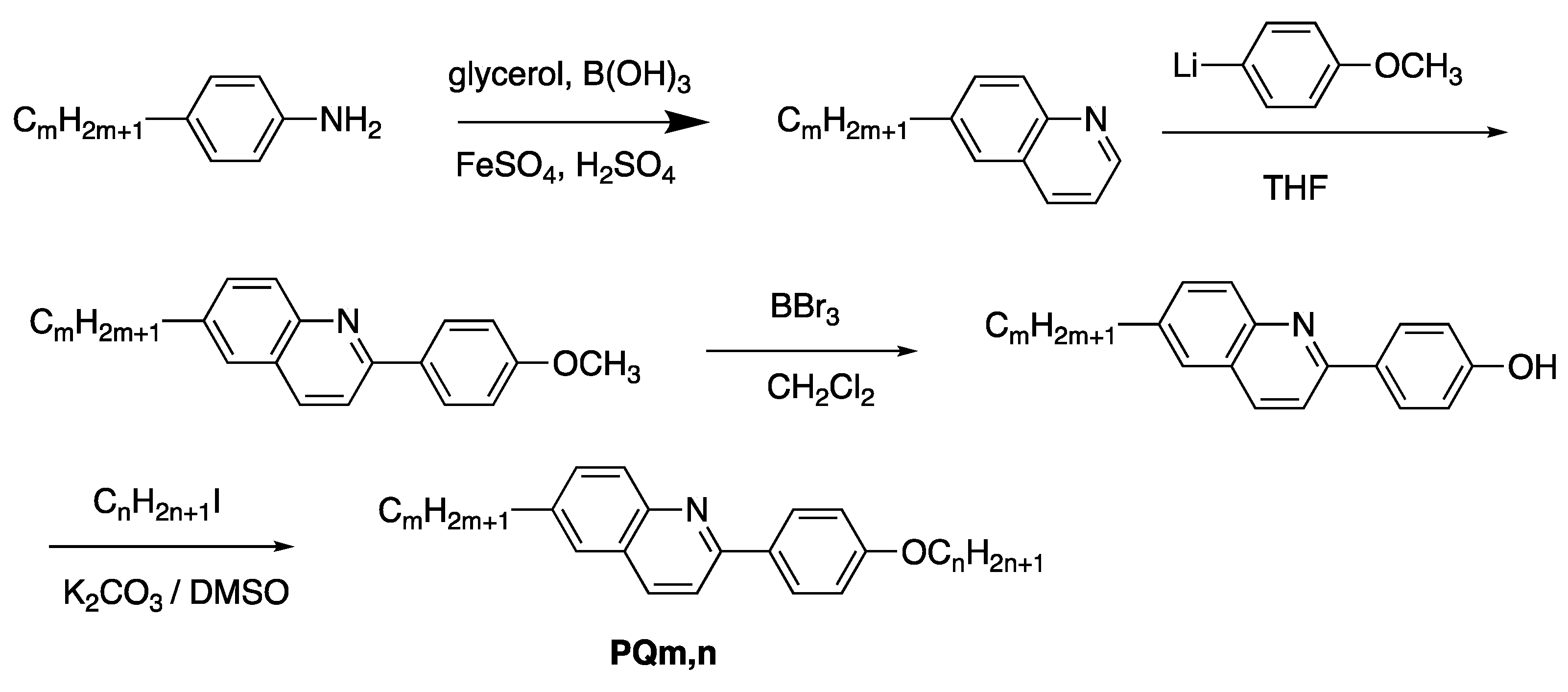
  50. Yokoyama, A.; Nishiyama, I.; Yoshizawa, A. 6-Alkyl-2-(4-alkyloxyphenyl)quinoline: A new smectic C base material. Ferroelectrics 1993, 148, 139–145. [Google Scholar] [CrossRef]
  51. Skraup, Z.H. Eine syntheses der chinolins. Monatshefte Für Chem. 1880, 1, 316–318. [Google Scholar] [CrossRef]
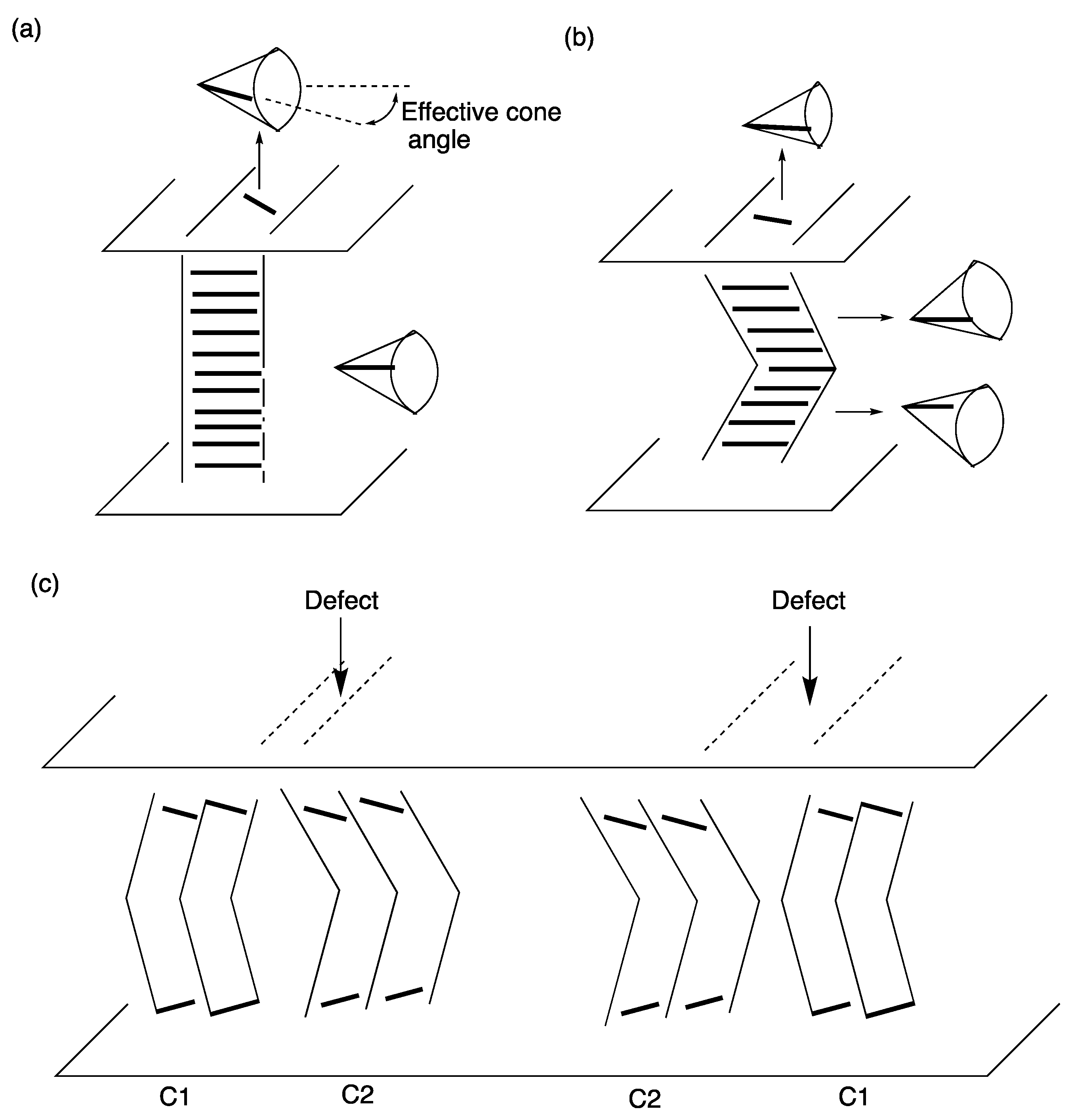
  52. Ishikawa, K.; Hashimoto, K.; Takezoe, H.; Fukuda, A.; Kuze, E. A practical method of preparing thin homogeneous ferroelectric smectic cells for electro-optical microsecond switches (II): SmA liquid crystal growth under a temperature gradient. Jpn. J. Appl. Phys. 1984, 23, L211–L213. [Google Scholar] [CrossRef]
  53. Hiji, N.; Ouchi, Y.; Takezoe, H.; Fukuda, A. Determination of chevron direction and sign of the boat-shaped disclination in surface-stabilized ferroelectric liquid crystals. Jpn. J. Appl. Phys. 1988, 27, L1–L4. [Google Scholar] [CrossRef]
  54. Clark, N.A.; Rieker, T.P. Smectic-C “chevron”, a planar liquid-crystal defect: Implications for the surface-stabilized ferroelectric liquid-crystal geometry. Phys. Rev. A 1988, 37, 1053–1056. [Google Scholar] [CrossRef] [PubMed]
  55. Mochizuki, A.; Yoshihara, T.; Iwasaki, M.; Nakatsuka, M.; Takanishi, Y.; Ouchi, Y.; Takezoe, H.; Fukuda, A. Electro-optical switching of bookshelf structure Sc*cells. Inst. Image Inf. Telev. Eng. 1990, 14, 21–27. [Google Scholar]
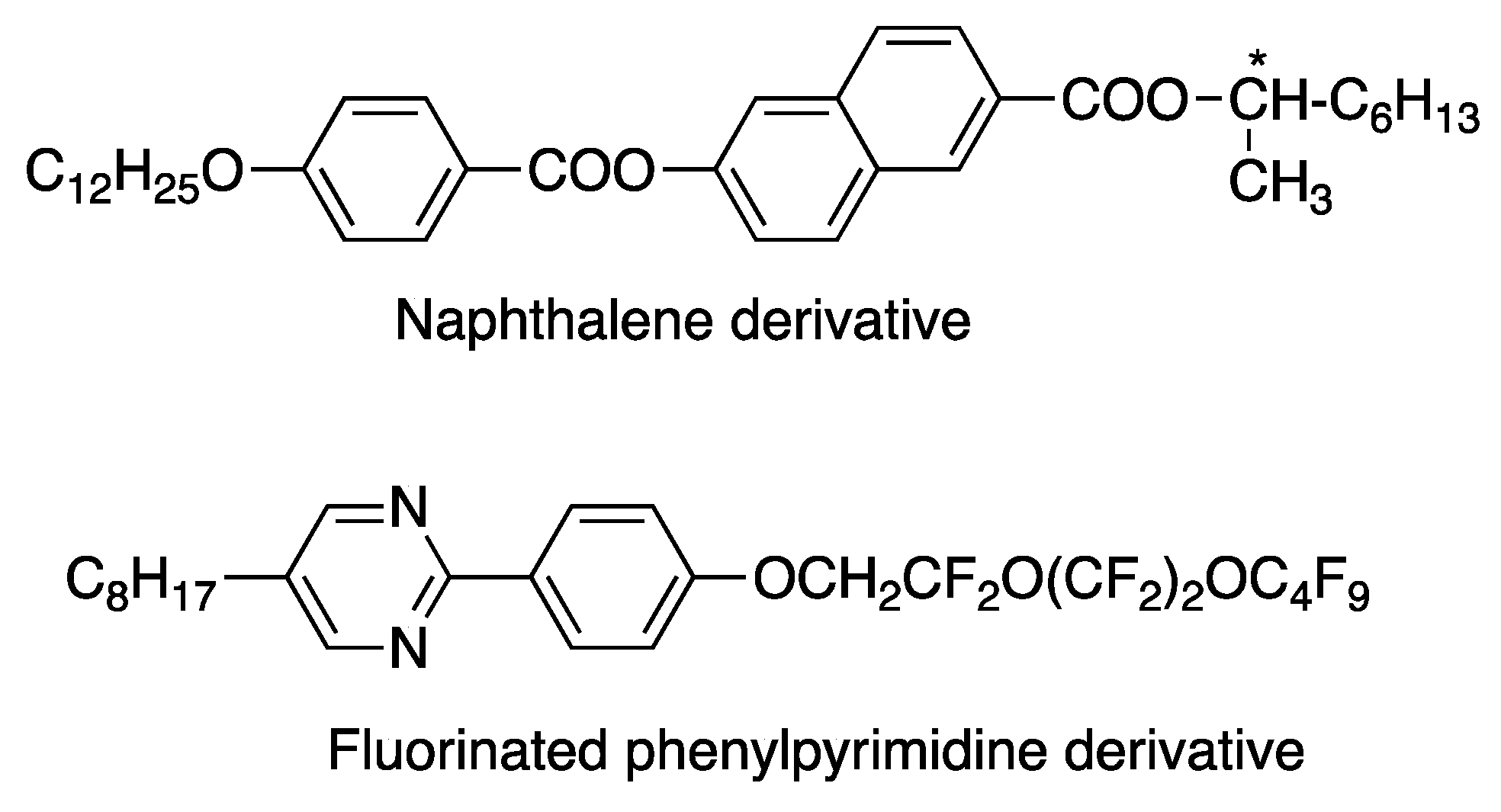
  56. Janulis, E.P.; Osten, D.W.; Radcliff, M.D.; Novack, J.C.; Tristani-Kendra, M.; Epstein, K.A.; Keyes, M.; Johnson, G.C.; Savu, P.M.; Spawn, T.D. Fluorinated liquid crystals: An update. In SPIE 1665, Liquid Crystal Materials, Devices, and Applications; SPIE: Bellingham, DC, USA, 1992. [Google Scholar] [CrossRef]
  57. Rieker, T.P.; Janulis, E.P. Dimerlike smectic-A and -C phases in highly fluorinated thermotropic liquid crystals. Phys. Rev. E 1995, 52, 2688–2691. [Google Scholar] [CrossRef]
  58. Lagerwall, J.P.F.; Giesselmann, F. Current topics in smectic liquid crystals. ChemPhysChem 2006, 7, 20–45. [Google Scholar] [CrossRef]
  59. De Vries, A. X-ray photographic studies of liquid crystals: II. Apparent molecular length and thickness in three phases of ethyl-p-ethoxybenzal-p-aminobenzoate. Mol. Cryst. Liq. Cryst. 1970, 11, 361–383. [Google Scholar] [CrossRef]
  60. De Vries, A. Experimental evidence concerning two different kinds of smectic C to smectic A transitions. Mol. Cryst. Liq. Cryst. 1977, 41, 27–31. [Google Scholar] [CrossRef]
  61. De Vries, A. The description of the smectic A and C phases and the smectic AC phase transition of TCOOB with a diffuse-cone model. J. Chem. Phys. 1979, 71, 25–31. [Google Scholar] [CrossRef]
  62. Spector, M.S.; Heiney, P.A.; Naciri, J.; Weslowski, B.T.; Holt, D.B.; Shashidhar, R. Electroclinic liquid crystals with large induced tilt angle and small layer contraction. Phys. Rev. E 2000, 61, 1576–1584. [Google Scholar] [CrossRef]
  63. Song, Q.; Nonnenmacher, D.; Giesselmann, F.; Lemieux, R.P. Tuning ‘de Vries-like’ properties in siloxane- and carbosilane-terminated smectic liquid crystals. J. Mater. Chem. C 2013, 1, 343–350. [Google Scholar] [CrossRef]
  64. Kaur, S.; Barthakur, A.; Mohiuddin, G.; Guta, S.P.; Dhara, S.; Pal, S.K. Observation of “de Vries-like” properties in bent-core molecules. Chem. Sci. 2022, 13, 2249–2257. [Google Scholar] [CrossRef]
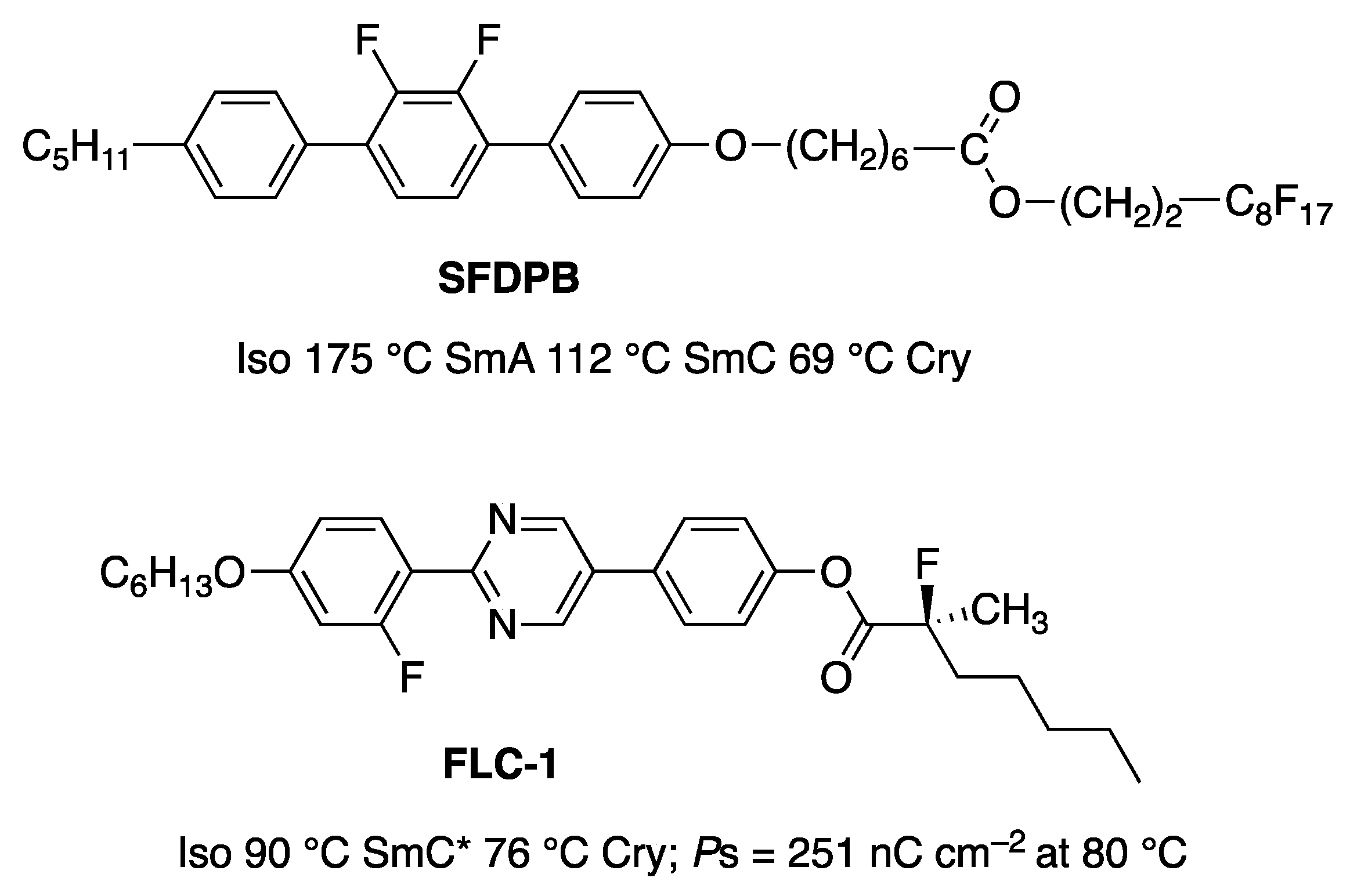
  65. Ishida, N.; Takanishi, Y.; Yamamoto, J.; Yoshizawa, A. Amphiphilic liquid crystal exhibiting the smectic A to smectic C phase transition without layer contraction. Appl. Phys. Express 2011, 4, 021701. [Google Scholar] [CrossRef]
  66. Giesselmann, F.; Zugenmaier, P.; Dierking, I.; Lagerwall, S.T.; Stebler, B.; Kaspar, M.; Hamplova, V.; Glogarova, M. Smectic-A*–smectic-C* transition in a ferroelectric liquid crystal without smectic layer shrinkage. Phys. Rev. E 1999, 60, 598. [Google Scholar] [CrossRef]
  67. Clark, N.A.; Bellini, T.; Shao, R.-F.; Coleman, D.; Bardon, S.; Link, D.R.; Maclennan, J.E.; Chen, X.-H.; Wand, M.D.; Walba, D.M.; et al. Electro-optic characteristics of de Vries tilted smectic liquid crystals: Analog behavior in the smectic A* and smectic C* phases. Appl. Phys. Lett. 2002, 80, 4097–4099. [Google Scholar] [CrossRef]
  68. Naciri, J.; Carboni, C.; George, A.K. Low transition temperature organosiloxane liquid crystals displaying a de Vries smectic A phase. Liq. Cryst. 2003, 30, 219–225. [Google Scholar] [CrossRef]
  69. Kapernaum, N.; Walba, D.M.; Korblova, E.; Zhu, C.; Jones, C.; Shen, Y.; Clark, N.A.; Gisselmann, F. On the origin of the “giant” electroclinic effect in a “de Vries”-type ferroelectric liquid crystal material for chirality sensing applications. ChemPhysChem 2009, 10, 890–892. [Google Scholar] [CrossRef] [PubMed]
  70. Prasad, S.K.; Rao, D.S.S.; Sridevi, S.; Lobo, C.V.; Rarana, B.R.; Naciri, J.; Shashidhar, R. Unusual dielectric and electrical switching behavior in the de Vries smectic A phase of two organosiloxane derivatives. Phys. Rev. Lett. 2009, 102, 147802. [Google Scholar] [CrossRef] [PubMed]
  71. Ghosh, S.; Nayek, P.; Roy, S.K.; Majumder, T.P.; Zurowska, M.; Dabrowski, R. Double-peak polarization current response in the unusual SmA* phase of a fluorinated high-tilt antiferroelectric liquid crystal. Eur. Phys. Lett. 2010, 89, 16001. [Google Scholar] [CrossRef]
  72. Garoff, S.; Meyer, R.B. Electroclinic effect at the A–C phase change in a chiral smectic liquid crystal. Phys. Rev. Lett. 1977, 38, 848–851. [Google Scholar] [CrossRef]
  73. Abdulhalim, I.; Moddel, G. Switching behviour and electro-optic response due to the soft mode ferroelectric effect in chiral smectic A liquid crystals. Liq. Cryst. 1991, 9, 493–518. [Google Scholar] [CrossRef]
  74. Tsuji, D.; Takanishi, Y.; Yamamoto, J.; Yoshizawa, A. Chiral liquid crystal trimer exhibiting an optically uniaxial smectic phase with a double-peak polarization. J. Phys. Chem. C 2012, 116, 8678–8687. [Google Scholar] [CrossRef]
  75. Schubert, C.P.J.; Müller, C.; Wand, M.D.; Giesselmann, F.; Lemieux, R.P. Electroclinic effect in a chiral carbosilane-terminated 5-phenylpyrimidine liquid crystal with ‘de Vries-like’ properties. Chem. Commun. 2015, 51, 12601–12604. [Google Scholar] [CrossRef] [PubMed]
  76. Swaminathan, V.; Panov, V.P.; Panov, A.; Rodriguez-Lojo, D.; Stevenson, P.J.; Gorecka, E.; Vij, J.K. Design and electro-optic investigations of de Vries chiral smectic liquid crystals for exhibiting broad temperature ranges of SmA* and SmC* phases and fast electro-optic switching. J. Mater. Chem. C 2020, 8, 4859–4868. [Google Scholar] [CrossRef]
  77. Link, D.R.; Natale, G.; Shao, R.; Maclennan, J.E.; Clark, N.A.; Körblova, E.; Walba, D.M. Spontaneous formation of macroscopic chiral domains in a fluid smectic phase of achiral molecules. Science 1997, 278, 1924–1927. [Google Scholar] [CrossRef]
  78. Guo, L.; Gorecka, E.; Pociecha, D.; Vaupotic, N.; Čepič, M.; Reddy, R.A.; Gornik, K.; Araoka, F.; Clark, N.A.; Walba, D.M.; et al. Ferroelectric behavior of orthogonal smectic phase made of bent-core molecules. Phys. Rev. E 2011, 84, 031706. [Google Scholar] [CrossRef]
  79. Kashima, S.; Chiba, M.; Takanishi, Y.; Yamamoto, J.; Yoshizawa, A. Polar order of an achiral taper-shaped liquid crystal in the uniaxial smectic A phase. J. Mater. Chem. C 2018, 6, 5521–5527. [Google Scholar] [CrossRef]
  80. Francescangeli, O.; Stanic, V.; Torgova, S.I.; Strigazzi, A.; Scaramuzza, N.; Ferrero, C.; Dolbnya, I.P.; Weiss, T.M.; Berardi, R.; Mucciolo, L.; et al. Ferroelectric response and induced biaxiality in the nematic phase of a bent-core mesogen. Adv. Funct. Mater. 2009, 19, 2592–2600. [Google Scholar] [CrossRef]
  81. Weissflog, W.; Baumeister, U.; Tamba, M.-G.; Pelzl, G.; Kresse, H.; Friedemann, R.; Hempel, G.; Kurz, R.; Roos, M.; Merzweiler, K.; et al. Unexpected liquid crystalline behaviour of three-ring bent-core mesogens: Bis(4-subst.-phenyl) 2-methyl-iso-phthalates. Soft Matter. 2012, 8, 2671–2685. [Google Scholar] [CrossRef]
  82. Khan, B.C.; Mukherjee, P.K. Isotropic to smectic-A phase transition in taper-shaped liquid crystal. J. Mol. Liq. 2021, 329, 115539. [Google Scholar] [CrossRef]
  83. Chen, X.; Korblova, E.; Glaser, M.A.; Maclennan, J.E.; Walba, D.M.; Clark, N.A. Polar in-plane surface orientation of a ferroelectric nematic liquid crystal: Polar monodomains and twisted state electro-optics. Proc. Natl. Acad. Sci. USA 2021, 118, e2104092118. [Google Scholar] [CrossRef] [PubMed]
  84. Caim, F.; Nava, G.; Barboza, R.; Clark, N.A.; Korblova, E.; Walba, D.M.; Bellini, T.; Lucchetti, L. Surface alignment of ferroelectric nematic liquid crystals. Soft Matter. 2021, 17, 8130–8139. [Google Scholar] [CrossRef] [PubMed]
  85. Kikuchi, H.; Matsukizono, H.; Iwamatsu, K.; Endo, S.; Anan, S.; Okunura, Y. Fluid layered ferroelectrics with global C∞V symmetry. Adv. Sci. 2022, 9, 2202048. [Google Scholar] [CrossRef] [PubMed]
  86. Chien, X.; Martinez, V.; Nacke, P.; Korblova, E.; Manabe, A.; Klasen-Memmer, M.; Freychet, G.; Zhernenkov, M.; Glaser, M.A.; Radzihovsky, L.; et al. Observation of a uniaxial ferroelectric smectic A phase. Proc. Natl. Acad. Sci. USA 2022, 119, e2210062119. [Google Scholar] [CrossRef]
  87. Nacke, P.; Manabe, A.; Klasen-Memmer, M.; Chen, X.; Martinez, V.; Freychet, G.; Zhernenkov, M.; Maclennan, J.E.; Clark, N.A.; Bremer, M.; et al. New examples of ferroelectric nematic materials showing evidence for the antiferroelectric smectic-Z phase. Sci. Rep. 2024, 14, 4473. [Google Scholar] [CrossRef]
Figure 1. (a) P-E curve in ferroelectrics. (b) Ferroelectric switching in the SmC* phase. (c) Electrical response in the switching current when applying a triangular wave voltage.
Crystals 14 00350 g001
Figure 2. Dark and bright states of FLCDs. The director is a unit vector showing the average direction of the molecular long axis.
Crystals 14 00350 g002
Figure 3. (a) P-E curve in antiferroelectric. (b) Electric field-induced transition between Sm C*A and SmC* phases. (c) Electrical response in the switching current when applying a triangular-wave voltage.
Crystals 14 00350 g003
Figure 4. Schematic image of the NF phase. The arrow shows a dipole moment.
Crystals 14 00350 g004
Figure 5. Molecular structures of DOBAMBC, MHPOBC, P-8-O-PIMB, RM734, and DIO.
Crystals 14 00350 g005
Figure 6. Phase symmetry of N, SmA, and SmC phases.
Crystals 14 00350 g006
Figure 7. Relationship between a molecule and its mirror image. The arrow shows a dipole moment. (a) An achiral molecule overlaps its mirror image. (b) A chiral molecule cannot overlap its mirror image.
Crystals 14 00350 g007
Figure 8. Helical structure of a chiral smectic C phase.
Crystals 14 00350 g008
Figure 9. (a) Surface-stabilized bistable states. (b) The definition of tilt angle.
Crystals 14 00350 g009
Figure 10. Sense of polarization.
Crystals 14 00350 g010
Figure 11. (a) Flexoelectric polarization in the splay deformation and (b) that in the bend deformation.
Crystals 14 00350 g011
Figure 12. Schematic illustration of molecular organization of tapered molecules in a nematic phase with polar order.
Crystals 14 00350 g012
Figure 13. Molecular structure and phase-transition temperatures of MONBIC. The carbon atoms of MONBIC are numbered as shown in the figure.
Crystals 14 00350 g013
Figure 14. The temperature dependence of the tilt angle, as determined by POM and XRD measurements. TAC* is the SmA–SmC* phase-transition temperature. The picture was taken from [37]. Copyright (1995) Taylor & Francis Ltd.
Crystals 14 00350 g014
Figure 15. 13C NMR spectra of MONBIC in the isotropic liquid, SmA, and SmC* without sample-spinning. The numbers are carbon numbers indicated in Figure 13. The picture was taken from [37]. Copyright (1995) Taylor & Francis Ltd.
Crystals 14 00350 g015
Figure 16. Microscopic behavior of MONBIC in the SmA and SmC* phases.
Crystals 14 00350 g016
Figure 17. (a) Temperature dependence of 13C T1 values of C2, C12, and C24 of MONBIC in the Iso, SmA, and SmC*. (b) That of 13C T1ρ values of C21 of MONBIC in the SmA and SmC*. The carbon numbers (C2, C12, and C24) are indicated in Figure 13.
Crystals 14 00350 g017aCrystals 14 00350 g017b
Figure 18. Temperature dependence of 13C T1 values of C12, C20, and C21 of MONBIC in the SmA and SmC* phases. The carbon numbers (C12, C20, and C21) are indicated in Figure 13.
Crystals 14 00350 g018
Figure 19. Molecular deformation for the core part. The estimated long axis is shown. The picture was taken from [37]. Copyright (1995) Taylor & Francis Ltd.
Crystals 14 00350 g019
Figure 20. Model for molecular organization near the SmA–SmC* transition.
Crystals 14 00350 g020
Figure 21. Molecular structure of chiral dopants, CD-1 [42], CD-2 [43], CD-3 [38], and CD-4 [44]. The carbon indicated by asterisk is an asymmetric carbon.
Crystals 14 00350 g021
Figure 22. Molecular structure of MOPBIC.
Crystals 14 00350 g022
Figure 23. Synthetic scheme of MFPYP.
Crystals 14 00350 g023
Figure 24. Model for core–core chirality transfer. Reprinted with permission from [40]. Copyright (2001) American Chemical Society.
Crystals 14 00350 g024
Figure 25. Molecular structures of the 2-ring and 3-ring phenylpyrimidine derivatives.
Crystals 14 00350 g025
Figure 26. Synthetic scheme of PQm,n.
Crystals 14 00350 g026
Figure 27. Rotational viscosity for mixtures A and B as a function of reciprocal temperature. The rotational viscosity was obtained from the following equation, η = τ·PE/(1.75sin2θ). The picture was taken from [50]. Copyright (1993) Taylor & Francis Ltd.
Crystals 14 00350 g027
Figure 28. (a) Bookshelf-layer structure. (b) Chevron-layer structure. (c) Defects in boundaries between the two different chevron-layer structures.
Crystals 14 00350 g028
Figure 29. Molecular structures of materials stabilizing a bookshelf-layer structure in the SmC phase. The carbon indicated by asterisk is an asymmetric carbon.
Crystals 14 00350 g029
Figure 30. Typical molecules possessing de Vries-like properties, TSiKN65 [62], QL5-n [63], QL6-n [63], and BC-n [64].
Crystals 14 00350 g030
Figure 31. Molecular structures and physical properties of the amphiphilic compound (SFDPB) and the ferroelectric liquid crystal (FLC-1).
Crystals 14 00350 g031
Figure 32. Layer spacing of SFDPB in the SmA and SmC phases as a function of reduced temperature. The picture was taken from [65]. Copyright (2011) The Japan Society of Applied Physics.
Crystals 14 00350 g032
Figure 33. Electroclinic switching in an SmA* phase.
Crystals 14 00350 g033
Figure 34. Model for the molecular organization in the SmA phase of SFDPB. The picture was taken from [65]. Copyright (2011) The Japan Society of Applied Physics.
Crystals 14 00350 g034
Figure 35. Schematic illustration of electro-optical switching in the de Vries A phase of SFDPB doped with FLC-1.
Crystals 14 00350 g035
Figure 36. Molecular structure of the chiral trimer, MOHBC.
Crystals 14 00350 g036
Figure 37. Optical textures of MOHBC between homogeneously aligned glass plates in the SmA*-L phase with ±8 V μm−1 or without an electric field. The picture was taken from [74]. Copyright (2012) American Chemical Society.
Crystals 14 00350 g037
Figure 38. Electrical response in the switching current of MOHBC (a) at TTIA* = −3 K in the SmA*-H phase, (b) TTIA* = −7 K in the SmA*-L phase, (c) TTIA* = −0 K in the SmA*-L phase, and (d) TTIA* = −4.5 K in the SmA*-L phase near the SmA*-L–SmC* phase transition upon application with a triangle-wave switching field of ±8 V µm−1 at a frequency of 15 Hz. The picture was taken from [74]. Copyright (2012) American Chemical Society.
Crystals 14 00350 g038
Figure 39. Binary phase diagram for mixtures of MOHBC with its enantiomer. The picture was taken from [74]. Copyright (2012) American Chemical Society.
Crystals 14 00350 g039
Figure 40. Model for the double-peak polarization. The picture was taken from [74]. Copyright (2012) American Chemical Society.
Crystals 14 00350 g040
Figure 41. (a) Molecular structure and phase-transition temperatures of W586. (b) Model for the molecular organization of W586 in the SmAdPF phase with E > Eth.
Crystals 14 00350 g041
Figure 42. Spontaneous polarization as a function of temperature. The hysteresis loop recorded at 125 °C is shown in the inset. Reprinted with permission from [78]. Copyright (2011) American Physical Society.
Crystals 14 00350 g042
Figure 43. Molecular structure and phase-transition temperatures of DFPYCB.
Crystals 14 00350 g043
Figure 44. (a) An optical texture of a sample in a 2 μm homogeneously aligned cell at 120 °C in the SmA phase and (b) that on application with a triangle wave switching field of 15 V μm−1 at a frequency of 1 Hz. The picture was taken from [79]. Copyright (2018) Royal Society of Chemistry.
Crystals 14 00350 g044
Figure 45. Switched polarization in the SmA phase at 118 °C and that in the isotropic liquid at 150 °C as a function of the electric field at a frequency of 1 Hz. The picture was taken from [79]. Copyright (2018) Royal Society of Chemistry.
Crystals 14 00350 g045
Figure 46. Molecular organization model for the polar ordering of DFPYCB in the SmA phase. The picture was taken from [79]. Copyright (2018) Royal Society of Chemistry.
Crystals 14 00350 g046
Figure 47. Molecular structure of the ferroelectric SmA compound.
Crystals 14 00350 g047
Figure 48. POM textures, 2D small-angle X-ray diffraction patterns, electric displacement–electric field (DE) hysteresis curves in the N and SmAF phases of the compound. (a) Polarized optical textures observed at 135 °C (SmAF) and 160 °C (N). (b) 2D SAXD patterns at 135 °C (SmAF) and 160 °C (N). (c) D–E curves at 130 °C (SmAF) and 160 °C (N). This picture was taken from [85].
Crystals 14 00350 g048
Disclaimer/Publisher’s Note: The statements, opinions and data contained in all publications are solely those of the individual author(s) and contributor(s) and not of MDPI and/or the editor(s). MDPI and/or the editor(s) disclaim responsibility for any injury to people or property resulting from any ideas, methods, instructions or products referred to in the content.

