Article

Modeling 0.3 THz Coaxial Single-Mode Phase Shifter Designs in Liquid Crystals with Constitutive Loss Quantifications

1
Beijing Key Laboratory of Millimeter Wave and Terahertz Technology, School of Integrated Circuits and Electronics, Beijing Institute of Technology, Beijing 100081, China
2
Advanced Research Institute of Multidisciplinary Science, Beijing Institute of Technology, Beijing 100081, China
3
Department of Electrical and Electronic Engineering, Imperial College London, London SW7 2AZ, UK
*
Author to whom correspondence should be addressed.
Crystals 2024, 14(4), 364; https://doi.org/10.3390/cryst14040364
Submission received: 18 March 2024 / Revised: 5 April 2024 / Accepted: 10 April 2024 / Published: 11 April 2024

Abstract

:
This work proposes and examines the feasibility of next-generation 0.3 THz phase shifters realized with liquid crystals (LCs) as tunable dielectrics coaxially filled in the transmission line. The classic coaxial transmission line topology is robust to electromagnetic interference and environmental noise, but is susceptible to higher-order modes from microwave to millimeter-wave towards terahertz (THz) wavelength ranges, which impedes the low-insertion-loss phase-shifting functionality. This work thus focuses primarily on the suppression of the risky higher-order modes, particularly the first emerging T E 11 mode impacting the dielectric loss and metal losses in diverse manners. Based on impedance matching baselines at diverse tuning states of LCs, this work analytically derives and models two design geometries; i.e., design 1 for the coaxial geometry matched at the isotopically referenced state of LC for 50 Ω, and design 2 for geometry matched at the saturated bias of LC with the maximally achievable permittivity. The Figure-of-Merit for design 1 and design 2 reports as 35.15°/dB and 34.73°/dB per unit length, respectively. We also propose a constitutive power analysis method for understanding the loss consumed by constitutive materials. Notably, for the 0.3 THz design, the isotropic LC state results in an LC dielectric loss of 63.5% of the total input power (assuming 100%), which becomes the primary constraint on achieving low-loss THz operations. The substantial difference in the LC dielectric loss between the isotropic LC state and saturated bias state for the 0.3 THz design (35.76% variation) as compared to that of our past 60 GHz design (13.5% variation) indicates that the LC dielectric loss’s escalating role is further enhanced with the rise in frequency, which is more pronounced than the conductor losses. Overall, the results from analytical and finite-element optimization in this work shape the direction and feasibility of the unconventional THz coaxial phase shifting technology with LCs, actioned as continuously tunable dielectrics.

1. Introduction

The evolving landscape of wireless communication [1,2,3], driven by the Internet of Things (IoT) paradigm [4,5], has catalyzed the development of next-generation communication (5G/6G) networks [6,7]. With escalating demands for bandwidth and data rates, the promising sub-millimeter-wave (sub-mmW) and terahertz (THz) [8,9] frequencies have emerged as focal points for research and development in this domain.
The traditionally acknowledged THz gap [10] has garnered significant attention and active research efforts over the past decade, resulting in strides towards bridging this technological barrier. Beyond its established applications in nondestructive sensing [11], imaging [12] and detection for security screening [13,14], and remote sensing for meteorological missions [15], as well as its burgeoning role in the biomedical industry [16,17], the utilization of THz frequencies in mainstream telecommunication scenarios [1,2], particularly in the context of the envisioned 6G phased array beam steering [18,19], introduces novel opportunities and accompanying challenges. The promising frequency bands for THz communication applications are graphically summarized in Figure 1, featuring exceptionally wide bandwidths (e.g., the window from 252 GHz to 296 GHz [1]) that allow high-data-rate communications.
Furthermore, the adoption of THz frequencies in 6G phased array beam steering enables other innovative applications, e.g., climate forecasting and early warning by meteorological radar wherein electronic beam steering may replace conventional mechanical rotation methods, hence offering enhanced agility and responsiveness. However, this transition presents various technical hurdles, including signal propagation challenges [15], particularly the power efficiency concerns [6,8], as well as the design complexity in antenna arrays and the beamforming algorithms [7,9]. As such, the integration of THz technology into radar or communication systems necessitates comprehensive research efforts to address these challenges and unlock the full potential of this emerging frontier.
To mitigate the effects of path loss over frequency and distance, THz communication is often associated with the use of narrow directional beams generated by large arrays. In such beam-steering antenna arrays, precise control of phase modulation for each radiating element becomes paramount, wherein phase shifters [20] are key components in the electronically steered array without bulky mechanical rotations. Traditional phase shifters typically rely on semiconductor-based switches [21] operating in discrete states (i.e., digital), limiting the resolution of phase variation and consequently compromising the spatial resolution of the steered beam. Continuous (analog) beam steering [22], however, has become feasible due to advancements in nematic liquid crystal (LC) microwave technology [23]. This entails integrating the continuously tunable anisotropic dielectric properties of LC materials [24] with microwave transmission lines [25] and components [26]. Figure 2 below outlines the scope and importance of LC-based variable phase shifters for mechanical rotation-free phased-array electronic beam-steering applications with ultra-high spatial resolutions.
Over the past two decades, various demonstrations have showcased LC-enabled tunable phase shifting [20,22,23] and reconfigurable frequency filtering [27,28], exhibiting commendable performance across microwave and millimeter-wave frequency ranges, typically up to V band [20] and W band [29,30]. The state of the art in this field has also witnessed the expansion towards a wider portfolio of LC-based photonic devices, e.g., [31] on THz tunable metamaterial with LCs for modulations of phase, intensity, and polarization, leading to potential applications in THz modulators, filters, and switches.
At the millimeter-wave domain, our recent research efforts have introduced the first LC coaxial phase shifter at 60 GHz [25], representing a notable advancement. The work [25] also highlights the trade-offs in performance metrics compared to previously proposed planar transmission line structures such as the inverted microstrip [32] and enclosed coplanar waveguide [20] configurations. Despite the compromises in performance metrics, the fully enclosed and symmetric electromagnetic structure and the polyimide (PI)-free manufacturing process associated with the proposed LC-filled coaxial phase shifters [25] offer significant advantages over the traditional planar transmission lines as accommodating structures for LCs (requiring time-consuming and thermally stringent PI processing and a rubbing process [20] for mechanically aligning LC molecules). In electromagnetic parlance, the coaxial structure radially filled with LCs features a single-dielectric encompassed device topology that eliminates the multi-dielectric competition and interface effects (coupling and radiation) as encountered by the planar solutions, hence the coaxial approach is less susceptible to undesirable higher-order modes. Compared with waveguides (single conductor) that require power-consuming magnets for biasing LC materials (e.g., >100 V [23]), the coaxial approach retains the advantage exhibited by the two-conductor system, i.e., enabling low-power electronic driving (e.g., 10 V) such as our previously demonstrated planar transmission line solutions [20,32] for accommodating LCs. The ease of noise-free unimodal operation, and the potential for PI-free rapid prototyping and mass production for arrayed devices on a panel, jointly position the coaxial approach as a compelling solution for the deployment of LC-based phase-reconfigurable components (mainly functioning by continuously varying the differential phase shifts between radiation elements) in 5G and future generation (6G) communication systems.
In our pioneering work combining coaxial transmission lines with LCs [25] at 60 GHz, we achieved a phase shifter by filling the coaxial transmission line with LCs in two extreme permittivity states, i.e., the LC isotropic state and the saturated biased tuning state, one of which serves as the referenced permittivity state for obtaining differential phase shifts dependent on the low-frequency voltage biasing field that leads to the permittivity variations concerning dielectric constant ( D k L C ) and dielectric dissipation factor ( D F L C ). The corresponding cross-section view of the coaxially distributed LC directors is sketched in Figure 3 below for the isotopically referenced state (minimally achievable permittivity) and the saturated biased state (maximally achievable permittivity), respectively.
In contrast to the rapidly evolving field of LC-based passive microwave and millimeter-wave tunable components, there has been relatively little documented progress in the realm of sub-THz and THz frequencies, especially concerning coaxially accommodating structures for LCs. Recent advancements in THz sources have demonstrated the generation of coaxial THz waves [33], highlighting the necessity and feasibility of the coaxial approach. Radially polarized THz beams are essential for implementing THz coaxial waveguide systems. Researchers [33] have leveraged the phenomenon of THz pulse production at semiconductor surfaces to launch THz pulses into coaxial waveguides. They found that radial transient photocurrents, induced by optical excitation at normal incidence, emit THz pulses with field distributions matching the coaxial waveguide’s mode. By adjusting the diameter of the optical excitation beam, efficient coupling into the TEM waveguide mode in a hollow coaxial THz waveguide was achieved, influencing the spatial profile of the generated radially polarized THz pulse. This straightforward technique opens avenues for further exploration and optimization in THz coaxial-typed TEM structure design and applications.

2. Materials and Methods
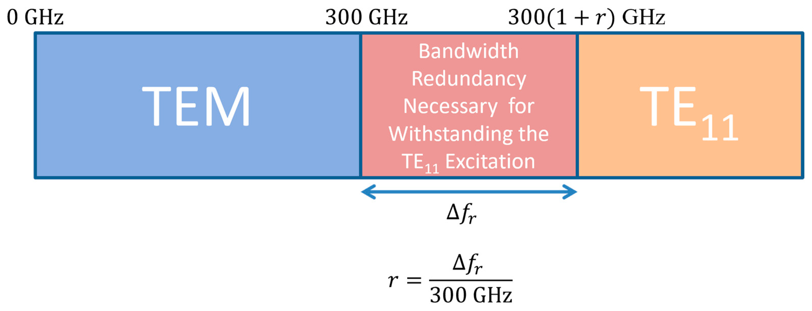
2.1. Analytical Models for T E 11 Mode Resistant 0.3 THz LC Coaxial Phase Shifter Designs

The cutoff frequency ( f c ) or the cutoff (critical) wavelength ( λ c ) of the first higher-order mode T E 11 is derived based on the averaged circumference, as denoted in Figure 4 below for the dashed circle with a critical radius ( r c ) given by Equation (1).
r c = D c o r e + T L C 2 ,
where D c o r e (diameter of the circular core line) and T L C (thickness of the coaxially-filled LC dielectrics) represent the key cross-section geometry of the LC-filled coaxial phase shifter.
The final equation of the cutoff frequency ( f c ) for the undesirable T E 11 mode is presented in Equation (2). Interested readers can refer to Appendix A for the intermediate derivation steps.
f c = v λ c = c π ( D c o r e + T L C ) ε e f f c π ( D c o r e + T L C ) D k L C ,
wherein v = c/ ε e f f represents the guided wave speed in the transmission line with effective permittivity ( ε e f f ) compared to the wave speed in vacuum (c). From our established work [25], the effective permittivity of the coaxial transmission line is de facto equaling the dielectric constant (Dk) of the filled dielectric (i.e., LC), as evidenced by our characterized maximum deviation between ε e f f and D k L C which, among all tuning states of LC, is less than 0.00045 [25], from which we also demonstrated numerically the LC dielectric fill factor reaching 99.82–99.90% (approaching the theoretically idealized 100% limit) for the coaxial topology of various LC thicknesses. This significantly reduces the need (and cost) for traditionally time-consuming and memory-hungry full-wave simulations for the device’s design and prototyping. As such, ε e f f here can be simplified into D k L C with reasonable confidence (a maximum uncertainty of 0.18%), applying for various dielectric thicknesses of LC (i.e., T L C ) at diverse tuning (biasing) states of different D k L C . The characteristic impedance ( Z c ) of the LC-filled coaxial phase shifter is given by Equation (3), taking the same approximation regarding ε e f f and D k L C .
Z c = 60 ε e f f l n ( D c o r e + 2 T L C D c o r e ) 60 D k L C l n ( D c o r e + 2 T L C D c o r e ) .
For the combined governing equations of a 50 Ω LC-filled coaxial phase shifter with the critical structure of T E 11 mode cutoff at f c , i.e., by combining Equations (2) and (3), the analytical solution of T L C and D c o r e is unique, as shown in Figure 5 below for the analytical solutions of T L C and D c o r e for the tunable dielectrics (Dk varying from 1 to 5 by way of illustration) across the targeting T E 11 mode cutoff frequency spectrum from 100 GHz to 500 GHz.
In our first characterization and analysis of the first LC-based coaxial phase shifter [25], we have identified the operating (tuning) range of the coaxial phase shifter from the LCs at the isotropic state to the LCs at the saturated bias state, corresponding to two extreme dielectric constants ( D k L C ) that the LCs exhibit in the coaxial setup. For the same GT3-24002 type of nematic LCs employed in this work, the two extreme D k L C -matching baseline designs we proposed link to two designs, respectively; i.e., a D k L C of 2.754 and a dielectric dissipation factor ( D F L C ) of 0.0111 correspond to design 1, which geometrically matches at the LC isotropic state, while a D k L C of 3.3 and a D F L C of 0.0032 correspond to the geometry of design 2, which is impedance matched at the LC saturated bias tuning state. The critical geometries for these two designs are illustrated in Figure 6 below, providing valuable insights into the relationship between dielectric constant matching and specific LC states. Further exploration of these designs could contribute to enhanced performance and understanding in LC-based applications.
Aimed at achieving 300 GHz (0.3 THz) single coaxial TEM mode operation, we allocate a 25% guard band allowance, equivalent to setting the T E 11 mode-cutoff critical structure at 375 GHz. By applying the two matching baselines, we define the corresponding geometry designs with T L C and D c o r e parameters. For design 1, matched at the LC isotropic state, T L C is set to 91.8 µm, and D c o r e to 61.5 µm. For design 2, matched at the LC saturated bias state, T L C is set to 89.5 µm, and D c o r e to 50.5 µm.
To fundamentally understand the dominating loss that compromises the LC-based phase shifter performance at THz, quantifying each loss element (metal loss, dielectric loss, reflection loss) that constitutes the total power loss (from input to output pathways) is a prerequisite. While vector network analyzer (VNA)-based experimental measurements can characterize the scattering parameters (S parameters) for the forward transmission ( S 21 ) and forward reflection ( S 11 ) of a two-port network (with port 1 and port 2), they fail to convey the constitutive material’s loss, e.g., the individual percentage of loss that is consumed by the LCs ( P L C ), core line metal ( P c o r e ), and housing metal ( P h o u s i n g ), respectively.
We thus present our analytically derived power dissipative loss formulas [25] for constitutive materials of the LC-based coaxial phase shifter in Equations (4)–(6), wherein each loss element here is derived analytically per unit length in a phasor form (denoted as P c o r e s 0 , P h o u s i n g s 0 , and P L C s 0 , respectively) and in accord with the cross-section coordinate system shown earlier in Figure 4.
P c o r e s 0 = I s 0 2 R = r = D c o r e 2 = 0 = 2 π σ E s r , 0 d d r 2 × π f σ μ σ π D c o r e ,
P h o u s i n g s 0 = r = D c o r e 2 + T L C = 0 = 2 π σ E s r , 0 d d r 2 × π f σ μ σ π ( D c o r e + 2 T L C ) ,
P L C s 0 = 2 π f ε 0 D k L C D F L C r = D c o r e 2 r = D c o r e 2 + T L C = 0 = 2 π E s r , 0 2 d d r .
where σ and μ denote conductivity and permeability, respectively. These analytically derived power densities per unit length are then integrated as per Equation (7) (surface integration) for deriving the metal losses, and as per Equation (8) (volume integration) for obtaining the LC dielectric loss. The integral operations are then solved numerically using full-wave electromagnetic simulations with Ansys HFSS (high-frequency structure simulator in version 2022 R1) based on the finite element method (FEM).
P c o r e ( o r   h o u s i n g ) = p c o r e ( o r   h o u s i n g ) d S ,
P L C = p L C d V .
The main simplifications (limitations) underpinning the analytical and numerical models here (compared to experimental research) lie in the surface roughness-free conductors (core line and grounding metal housing), as well as the frequency dispersion-free dielectrics (LC).

2.2. Full-Wave Simulation Models for the Two LC-Filled Coaxial Phase Shifter Designs

Electromagnetic full-wave calculations based on the finite-element method were conducted for the two designs. The computational domain under investigation as per Figure 4 is numerically partitioned into discrete volume elements, forming a mesh structure as depicted in Figure 7, wherein the collective sub-domains adhere to the governing equations (Maxwell’s) and prescribed boundary conditions (conductor-enclosed coaxial TEM mode as defined by two circular wave ports with electric field polarization pointing from the housing conductor radially towards the core line). Radiation boundary is not required in this setup due to the metal fully enclosed structure. The geometrically conforming tetrahedral meshes generated at 0.3 THz are inhomogeneous in size, i.e., finer at the critical parts of the core line surface (mesh with a minimum edge length of 0.023535 mm) as well as the LC dielectric volume (mesh with a minimum edge length of 0.0239014 mm), while being coarser at the housing conductor surface (mesh with a minimum edge length of 0.0687666 mm), as illustrated in Figure 7 for design 1 at the saturated bias state of LC.
Both design 1 and design 2 have a unit length of 1 cm, aiming for a convergence target of 0.02 in the maximum magnitude of the S-parameter variation between passes, denoted as max. delta S. The progression of each iterative pass also recorded the number of elements solved, as summarized in Figure 8 and Figure 9 for design 1 and design 2, respectively. From Figure 8, the computational solution for design 1 is converged after 5 passes (for both the isotropic and saturated biased states for the same geometry), with the solved elements amounting to 32,746 for the isotropic state of LC, and 33,594 for the saturated biased state. The statistics from Figure 9 indicate that the convergence takes slightly longer for design 2, with 6 passes required for the isotropic state (38,896 elements solved), and 7 passes for the saturated biased state (48,080 elements solved). These quantifications provide confidence in the electromagnetic behavior characterization numerically, which serves as a crucial foundation for further analysis and refinement of LC-based differential phase modulating components in THz applications.

3. Simulation Results of the Two Designs and Benchmark

Performance evaluation encompasses the ±25% bandwidth of 0.3 THz (i.e., from 225 GHz to 375 GHz), focusing on effective permittivity and guided wavelength shown in Figure 10, characteristic impedance shown in Figure 11, return loss, insertion loss, and phase shift differentially detailed in Section 3.1.
From Figure 10, ε e f f (the effective permittivity of the LC-filled coaxial transmission line) across the analyzed spectrum well matches with D k L C (the dielectric constant of the filled LC) for both designs and both tuning states. The maximum deviation is 0.007 (occurred for design 2 at the saturated bias tuning state of LC), translating into an error (uncertainty) of 0.21% at 0.3 THz (as compared to the maximum error of 0.18% reported at 60 GHz [25] for our previously proposed coaxially-filled LC phase shifter).
The impedance results from Figure 11 well agree with our design principle of setting the Dk-matching baseline at a specific tuning state of LC, which yields a relatively perfect matching geometry design at a specific biased state of LC (e.g., the geometry of design 1 obtains 50.06 Ω at 0.3 THz at the isotropic LC state, and the geometry of design 2 obtains 50.13 Ω at 0.3 THz at the saturated bias state of LC, both as per the design strategy). Meanwhile, this design principle, as we proposed, also results in an impedance mismatching status at the other extreme tuning state of LC for each design, as evidenced by the 45.75 Ω at 0.3 THz at the saturated biased state of LC for design 1, and the 54.87 Ω at 0.3 THz at the isotropic LC state for design 2.

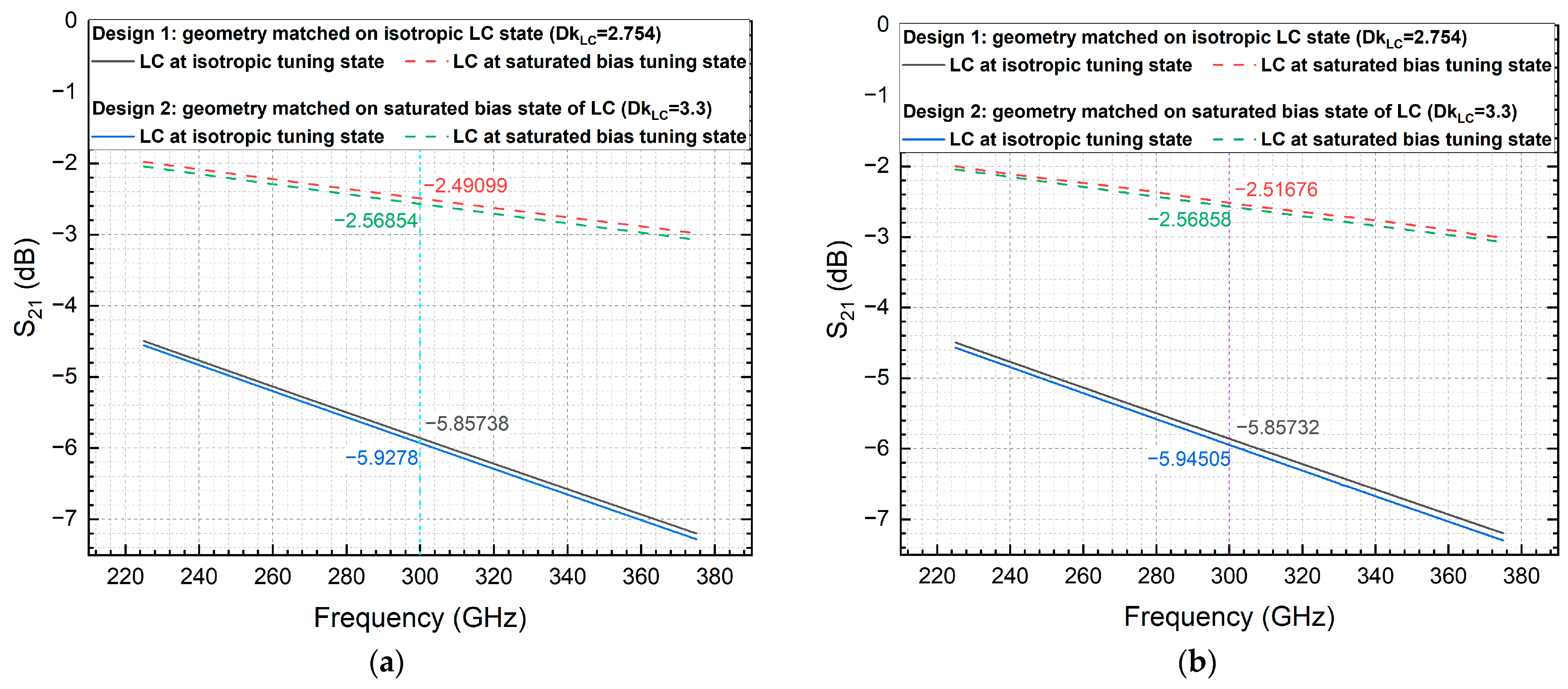
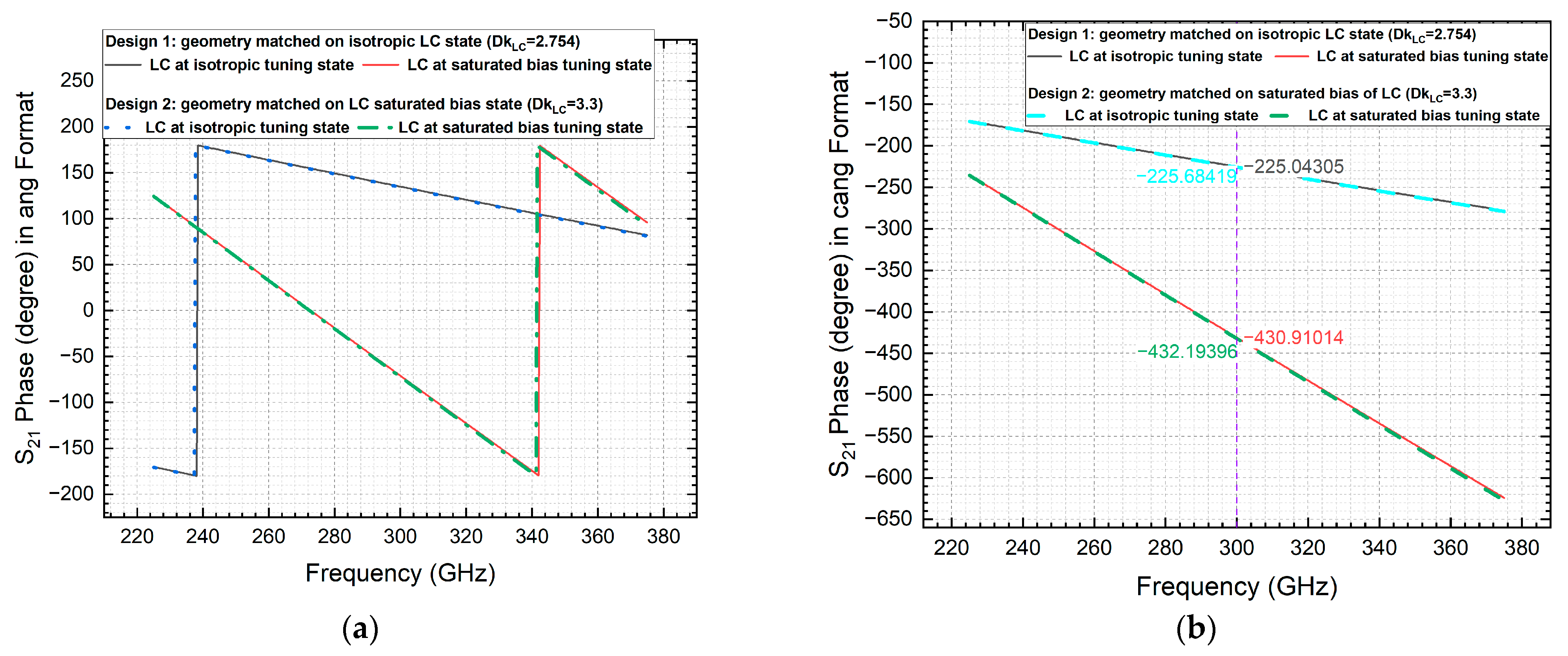
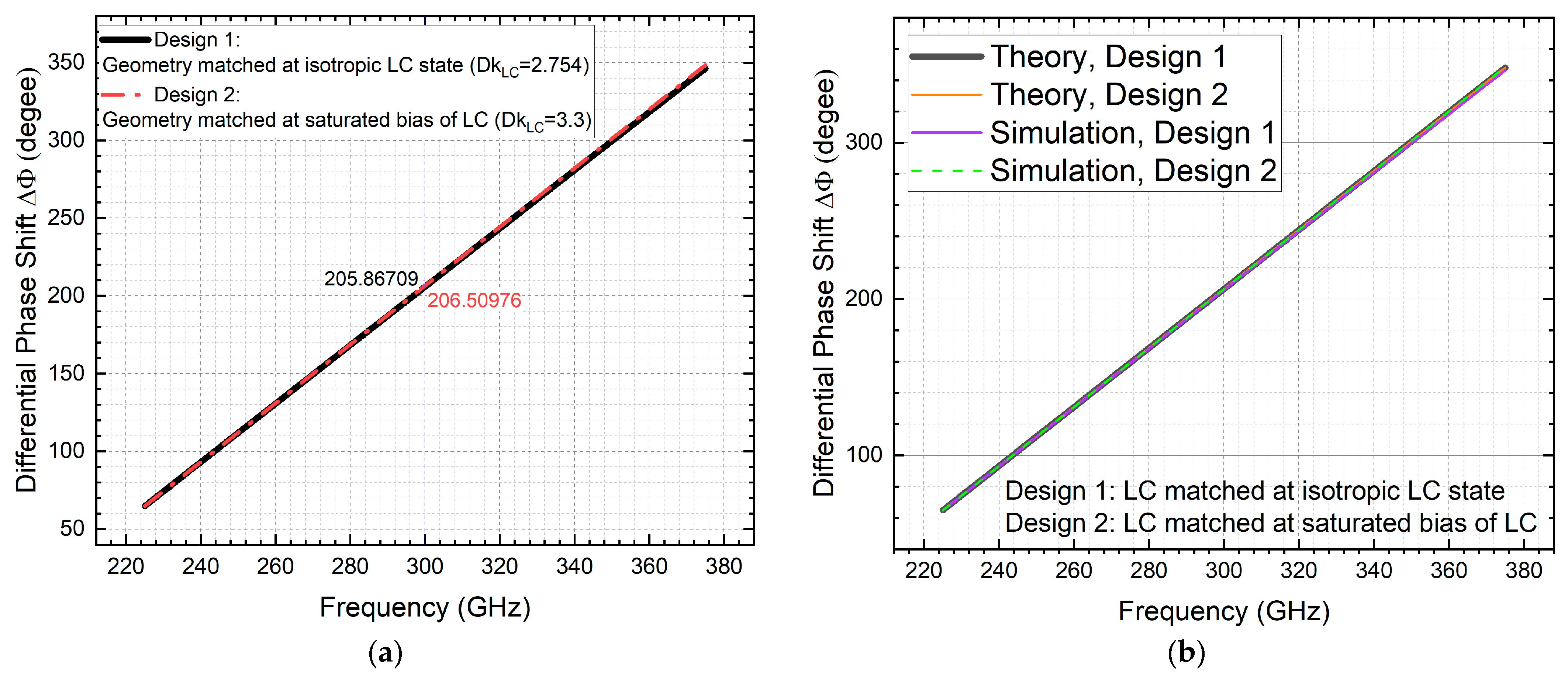
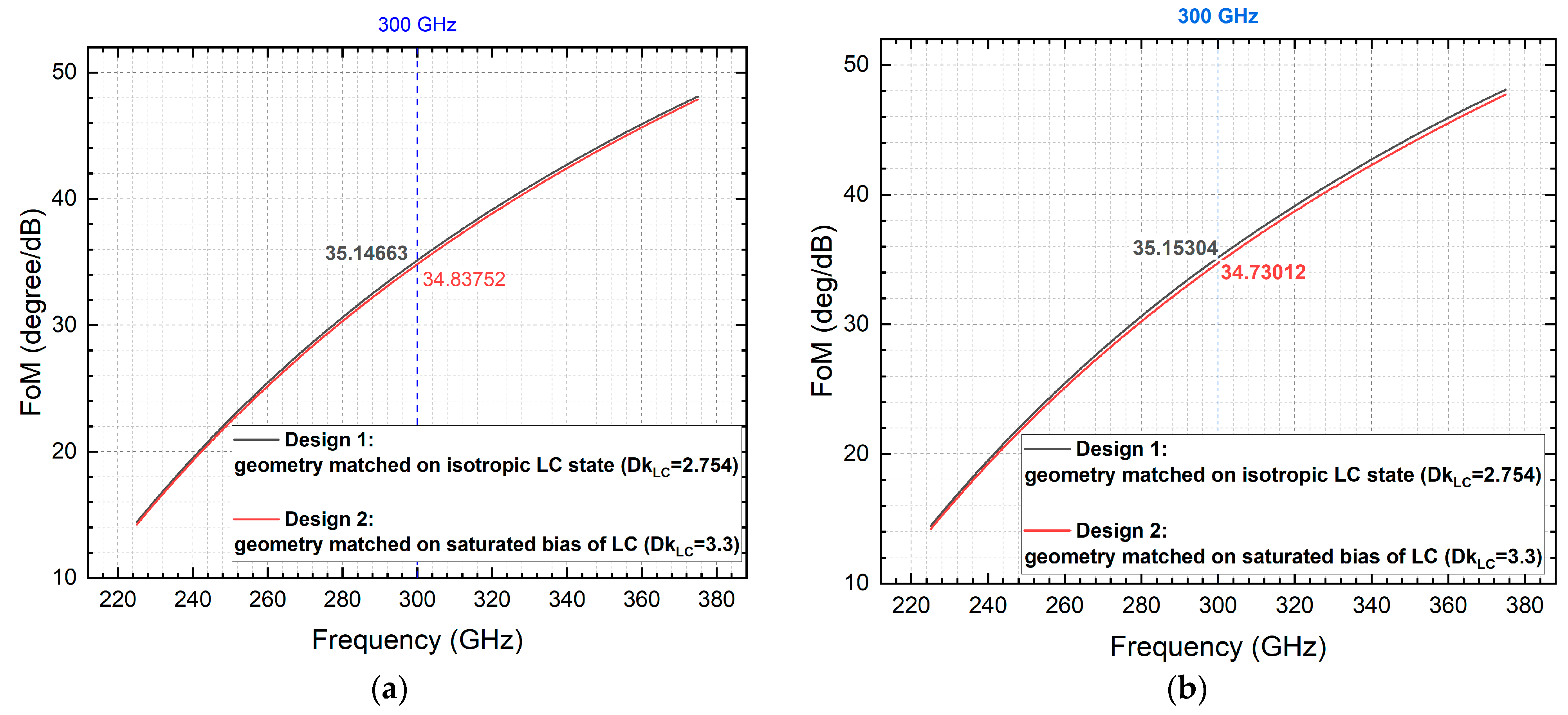
3.1. Scattering Parameters Quantification

Analysis of S 11 (see Figure 12) and S 21 (see Figure 13) in magnitude (dB) includes both cases of renormalizing to 50 Ω and without renormalizing to 50 Ω for both wave ports (port 1 for input and port 2 for output) during post-processing, providing comprehensive insights into the operational characteristics of the seemingly black-box system. These evaluations contribute to the optimization and understanding of LC-based components in THz applications, facilitating advancements in tunable device technology.
Without renormalizing the two ports, the results of S 11 in Figure 12a remove the impact of multi-reflections at the input and output ports, which limits the difference between the two designs. Instead, the results of the renormalized treatment well agree with the design principle, as evidenced by the 20–30 dB difference produced in S 11 between the two tuning states of LC (applying to both designs).
For both renormalized and non-renormalized treatments in Figure 13, the S 21 results exhibit similar trends of insertion loss increasing with frequency, and the most lossy case occurs at the isotropic LC state for both designs. The deviation in the maximum insertion loss of design 1 and design 2 at 0.3 THz amounts to 0.07042 dB/cm (non-renormalization treatment) and 0.08773 dB/cm (renormalization treatment), respectively.
Comparing the renormalized with non-renormalized results, about 0.02 dB/cm of difference in S 21 is observed for the two mismatched cases (more specifically, 0.01725 dB/cm of deviation happens at design 2 for the LC at isotropic tuning state, and 0.02577 dB/cm of deviation occurs at design 1 for the LC at saturated bias tuning state). Note that multi-reflection losses at the ports’ interfaces will be accounted for in the renormalized treatment, thus leading to a minor rise in the insertion loss as compared with those by the non-renormalization treatment.
The differential phase shift of interest, as deciphered from the simulated phase results of S 21 in Figure 14 for the two formats of presentation (Figure 14a in the conventional angular representation, and Figure 14b in the continuous angular manner for ease of understanding), is depicted in Figure 15a and benchmarked with the theoretically based derivation [25] in Figure 15b.
The maximum phase shift-to-maximum insertion loss ratio, i.e., the Figure-of-Merit (FoM) is quantified in Figure 16. The computational results based on renormalizing to 50 Ω treatment (35.15°/dB and 34.73°/dB for designs 1 and 2, respectively) lead to a minor deviation as compared with those with the non-renormalization treatment i.e., a 0.00641°/dB increase for design 1, and 0.1074°/dB decrease for design 2. For both post-processing methods, design 1 (geometry matched at the LC isotropic state) slightly outperforms design 2 (geometry matched at the saturated bias of LC), more specifically, by 0.30911°/dB (non-renormalization) and 0.42292°/dB (renormalization).

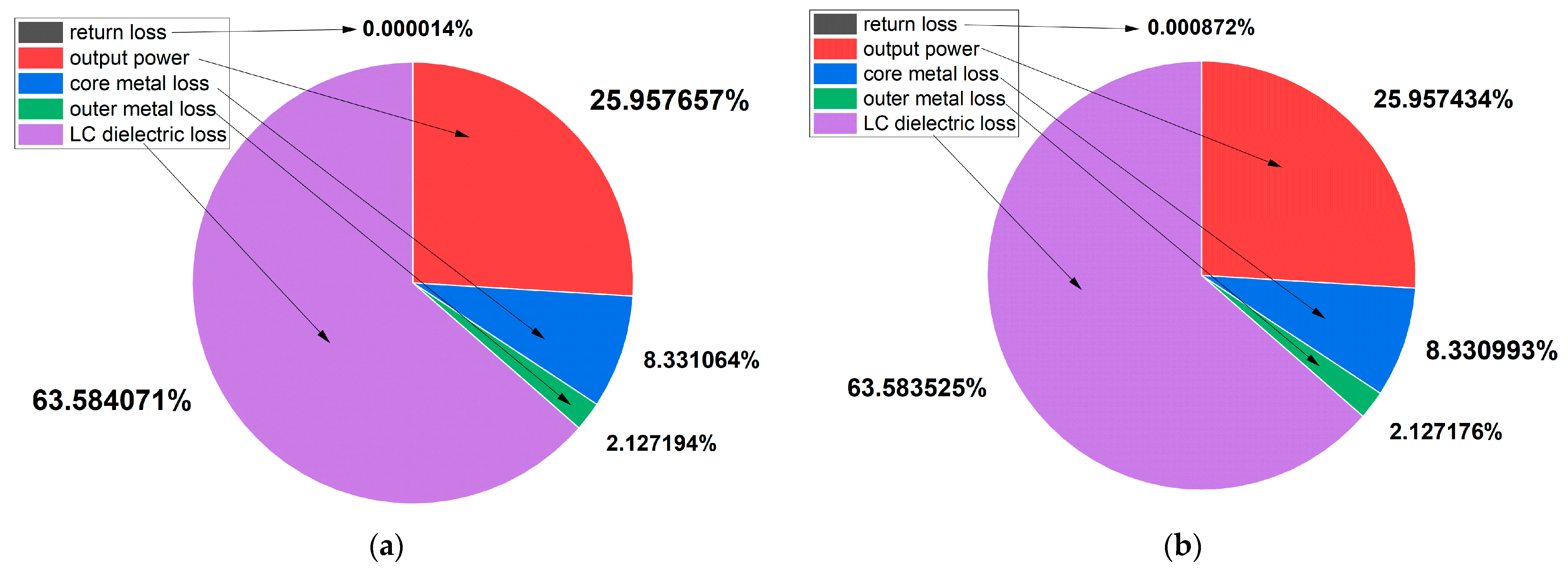
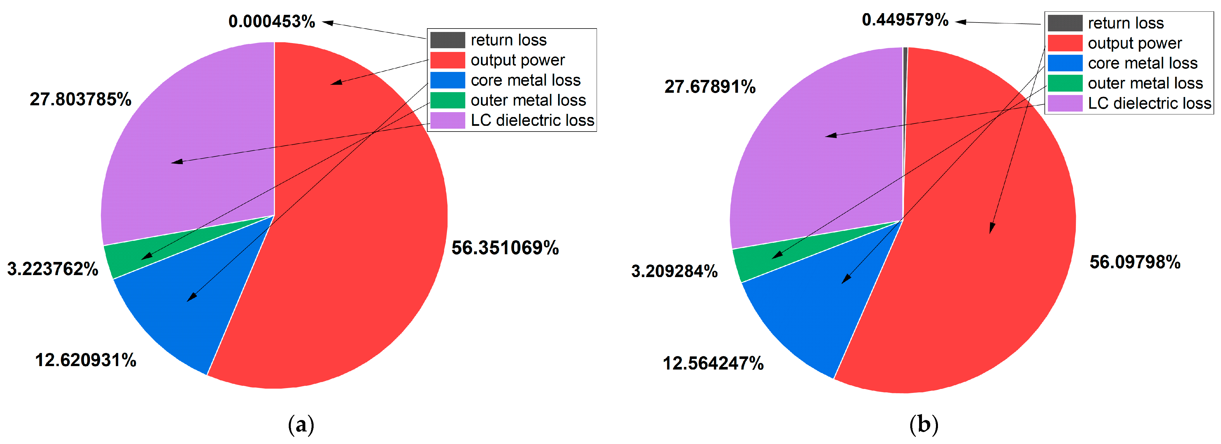
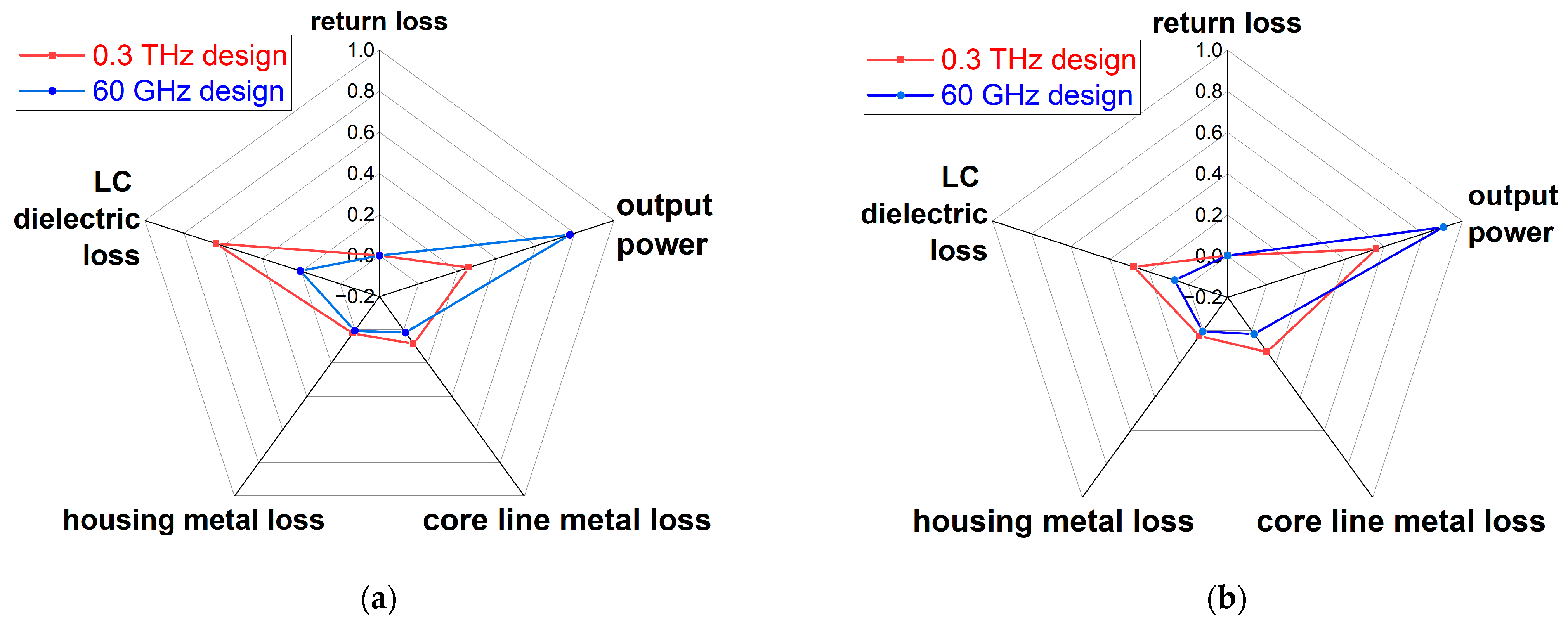
3.2. Constitutive Loss Components Quantification

By delving into the extension of LC-based components into the THz regime, the research seeks to pave the way for advancements in high-frequency transmission line technologies. The analysis encompasses considerations of both key performance metrics and the constitutive materials’ losses. For the lower insertion loss design (i.e., design 1 with the geometry’s impedance matched at the LC isotropic tuning state), the dissipative power analysis is conducted for the two tuning states at 0.3 THz, as quantified in Figure 17 for the isotropic LC state, and Figure 18 for the saturated bias state of LC. The results recorded comprise both non-renormalization and renormalization cases.
Agreeing with our theoretical explanation earlier, the evidenced return loss becomes more pronounced for the renormalization treatment in the mismatched case (i.e., at the saturated bias state of LC). For all cases and post-processing treatments, the major loss element is LC dielectric loss, amounting to 63.6% for the most lossy state (i.e., isotropic LC state), but this drops significantly to 27.7% for the least lossy state (i.e., saturated bias state of LC). Free from the surface roughness impact assumed in this work, the dissipative power consumed by the core line metal is 8.3% at the isotropic LC state ( D k L C = 2.754), and this rises to 12.6% at the saturated bias state of LC ( D k L C = 3.3). This phenomenon physically agrees well with our electromagnetic analysis of LC-based coplanar waveguide phase shifters at 90 GHz [34], concerning the electric field redistribution in a higher dielectric permittivity medium, which becomes particularly pronounced at a higher frequency.

4. Discussions and Optimization Opportunities
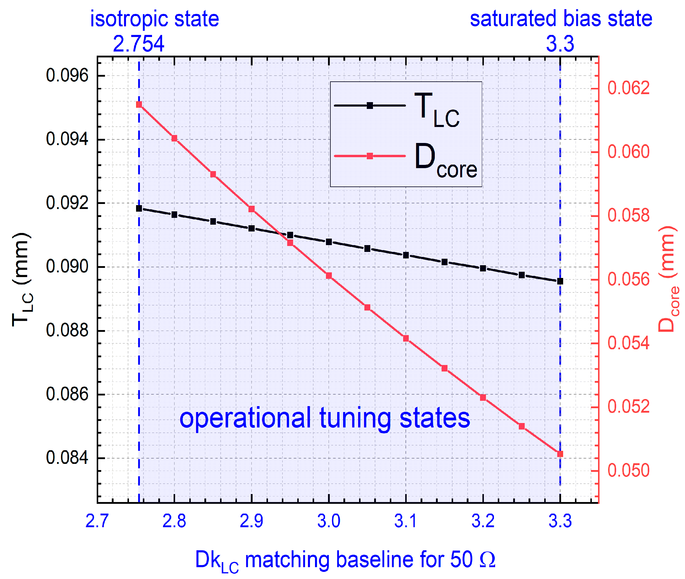
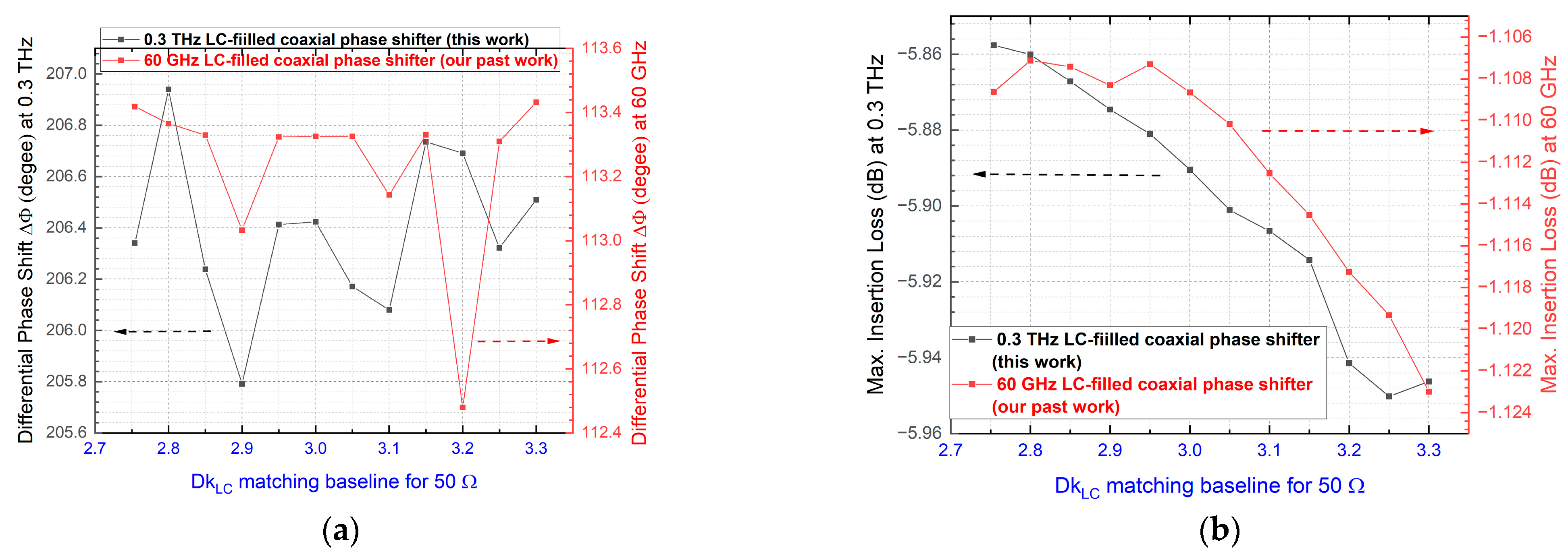
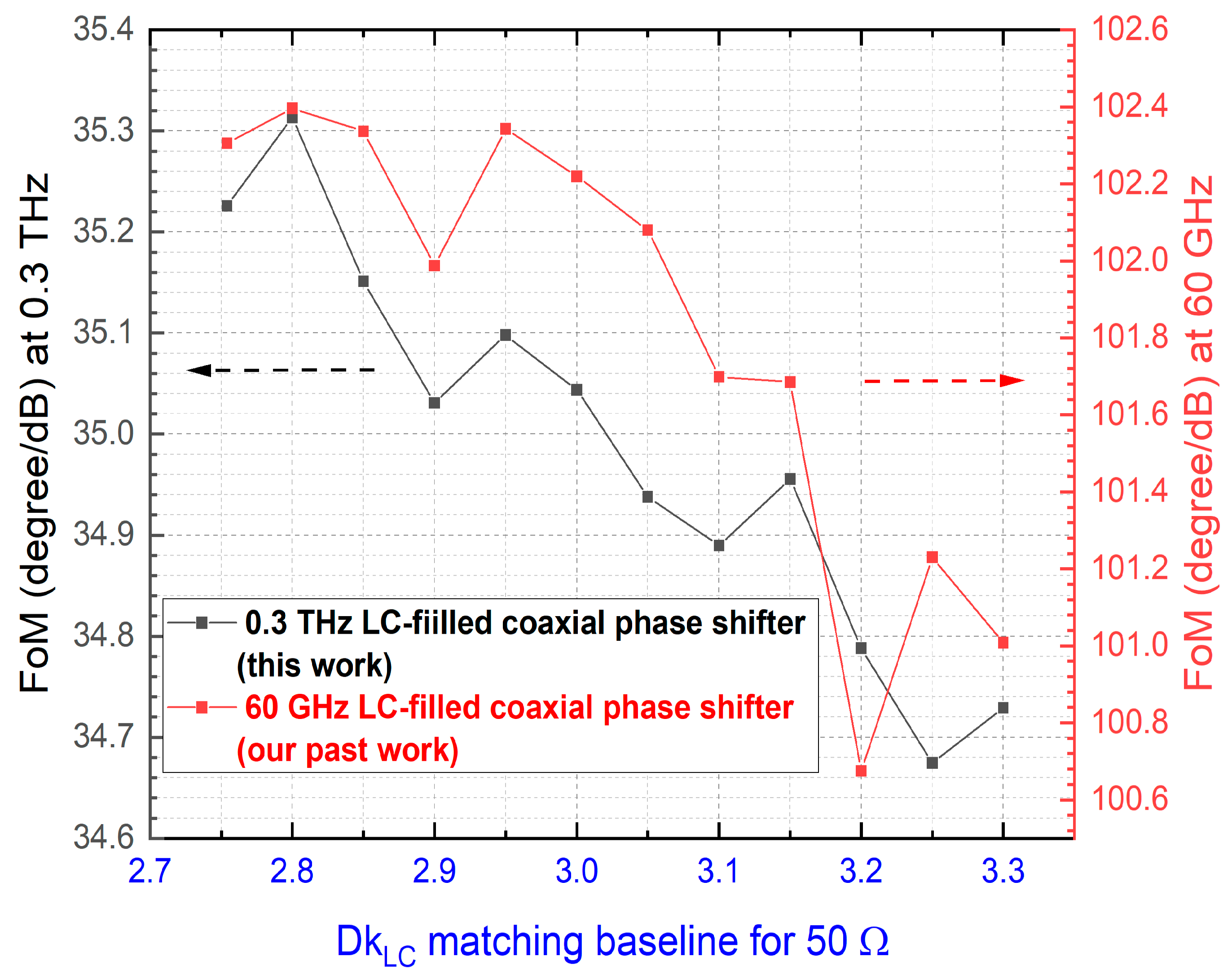
4.1. Optimization of D k L C Matching Baselines

Besides the current two designs presented (50 Ω matched at the two extreme values of the D k L C baselines, i.e., the isotropic LC state and the saturated bias state, respectively), the other design geometries that are impedance matched at the intermediate tuning states of LC (wherein D k L C and D F L C both change as per [25]) can be explored for potential performance optimization (loss minimization and phase shifting capability maximization). By way of illustration, Figure 19 summarizes the anti- T E 11 critical geometry (cross-section) of all these designs (diverse D k L C matching baselines) as derived from the combined Equations (2) and (3) shown earlier. Accordingly, the simulated performance indicators for these new designs are presented in Figure 20 and Figure 21, including a comparison with those designs at 60 GHz as we conducted in [25].
Albeit both designs of our noise-resistant, LC-filled coaxial phase shifters survive the T E 11 risk (as well as other higher-order parasitic modes), the intrinsic frequency impact on each loss element comes into play. Selecting the designs with 50 Ω matched at D k L C of 2.8 (the decision for achieving the optimum FoM for both the 0.3 THz design and the 60 GHz design as observed from Figure 21) leads to a slump in FoM, which declines from the optimum 102.4°/dB for the 60 GHz design to 35.3°/dB for the 0.3 THz design. To explain this significant FoM compromise, a constitutive material loss analysis is conducted again but conveyed in radar charts (spider plots) (Figure 22) to compare the 0.3 THz and 60 GHz designs (both 1 cm long) at the two extreme tuning states, respectively, i.e., Figure 22a for the isotropic LC state, and Figure 22b for the saturated bias state of LC. More specifically, for the cross-section sizes of the two designs (aiming for two frequencies that are vastly differing) under comparison, the 0.3 THz design is with T L C of 0.09164 mm and D c o r e of 0.06044 mm, while the 60 GHz one is with T L C of 0.3487 mm and D c o r e of 0.23 mm. Smooth metal surfaces are assumed in the computational models to rule out the surface roughness-induced computational uncertainties. Arguably, the skin effect and surface roughness (not accounted for in our models) will exacerbate the degradation of FoM from 60 GHz to 0.3 THz. Nevertheless, for both designs in Figure 22 at both tuning states, the LC dielectric volumetric loss occupies the largest proportion of the dissipated power loss. Notably, at the isotropic LC state for the 0.3 THz design, the LC dielectric loss amounts to 63.5% of the total input power (100% assumed), which becomes the key limiting factor for low-loss THz operations. The escalating role of the LC dielectric loss is further enhanced with the rise of frequency, as evidenced by the vast difference in the LC dielectric loss between the isotropic LC state and the saturated bias state for the 0.3 THz design (35.76% variation), as compared to that of the 60 GHz design (13.5% variation).

4.2. Other Limitations and Future Work

Note that the data acquisition and achieved results, as mentioned earlier, stem from the incorporation of a 25% guard band redundancy proposed for the anti- T E 11 excitation resilience, as portrayed in Figure 23 below, with the reserved guarding bandwidth denoted as ∆ f r , and representing it into the guarding ratio (r) format in percentage. This conservative approach of introducing ∆ f r reservation leads to distinct critical geometries and consequent performance variations. The pre-specified 25% redundancy raises questions about its level of conservatism, prompting a thorough exploration in the future optimization work for potential refinements of the guarding ratio (r) towards performance advancements. Looking back into Equation (2) which we derived and combining our LC device fabrication experience [20], the precise control of the filled LC thickness ( T L C ) during the device assembling and the temperature stability of LC permittivity ( D k L C ) during the device operation are critical for ensuring the dominance of the TEM mode over the T E 11 mode for the targeted operating frequency of 0.3 THz. Interestingly, it remains a challenge to achieve precise control over the mode selection (both theoretically and experimentally), the research question of which is inspiring our future work on multi-mode analysis and experiments.
Furthermore, our current design is based on our analytical model of the T E 11 cutoff wavelength as the averaged circumference of the coaxial structure, which assumes the circle at the half thickness of the LC layer. Whether this critical structure assumption is too conservative or not merits further investigation to re-evaluate our T E 11 cutoff model. Besides the need to validate the conservativeness of the proposed guarding band allowance, there is another research question regarding the cutoff wavelength validation, i.e., assessing the conservativeness of our current assumption (derivation based on the half thickness of the LC layer). More specifically, this question can be transferred to identifying the critical radius ( r c ) of the critical (cutoff) circle as we depicted in Figure 4 earlier. Numerical parameterization of r c can be conducted, e.g., from D c o r e /2 to D c o r e / 2 + T L C . The corresponding critical structural geometry, and the resulting differential phase shift, insertion loss, and hence FoM, are to be quantified and compared with the designs based on our current r c = ( D c o r e + T L C )/2 assumption underpinning this work.
With the ever-improving performance and ever-increasing role that LCs play in the mmW and THz regimes, developing LC-embedded THz system precursors in various spatiotemporal scales with open-source computation packages targeting full-wave LC-filled THz phase-shifting device solutions will be highly sought after in the quest for cost-effective design and quick prototyping with reasonably accurate predictions. With the simulation data built up for designs of various critical structures with diverse permittivity-matching baselines, artificial intelligence (e.g., machine learning [35]) may become another enabler to expand and deepen the suite of LC-filled coaxial transmission line techniques, including our ongoing work underway on bending (for miniaturization) and quarter-wave stubs implementation (for bandstop filtering applications).
Concerning the limitation of the dissipative loss analysis conducted in this work, conductor surface roughness and its impact on insertion loss (and differential phase shift) have yet to be considered. Existing theoretical and empirical models of conductor surface roughness (e.g., the snowball model [36]) are largely reported in microwave and millimeter-wave regimes with debates on their accuracy, for which our future work is envisaged to propose the THz correlation for the additional Ohmic losses on the core line and the grounding metal housing due to surface roughness. Furthermore, the other main limitation of the current work with dispersion-free assumption for LCs will be addressed by conducting time domain dielectric spectroscopy for accurately characterizing the permittivity and dissipation factor response of the LCs over the 0.3 THz wavelength ranges (from 225 GHz to 375 GHz). The tuning speed of the proposed device at different biasing voltages while subject to different environmental temperature conditions will also be measured in our future experimental work.

5. Concluding Remarks

The quest for higher bandwidth has stimulated the use of higher frequencies, for which the leap from gigahertz (GHz) to terahertz (THz) [37] represents one of the core research activities to enable next-generation 6G communications [38] and other smart applications. Despite tremendous progress in liquid crystal (LC) microwave technologies and devices realized by planar and non-planar topologies in various formats of transmission lines (e.g., inverted microstrips) or waveguides with decent performance, the combination potential of LCs with the classic coaxial transmission line for THz phase shifting has yet been explored. As such, this modeling study initiates the analytical and simulated investigations with the constitutive materials’ loss analysis into the LC coaxially-filled THz phase shifters operating with a single mode at 0.3 THz by ruling out the higher-order parasitic modes with a guard banding strategy. With the noise-free operation, the proposed LC-enabled phase-shifting device holds promise for feeding THz phased-array antennas, enabling high spatial resolution beam-steering applications in the 0.3 THz window, targeting 6G communications, THz meteorological radar imaging, and THz astronomy. The implications from the current THz phase shifter study are transferrable to other THz reconfigurable components (e.g., LC-filled coaxial filters) in terms of the constitutive loss and impedance matching strategy for enhanced FoM. To fully unlock the low-loss application potential, however, in recognition of the significantly escalated role of LC dielectric loss at 0.3 THz as compared to that of the 60 GHz mmW case, there is a pressing need to develop low-dissipating-factor LCs engineered for THz to stay competitive against other tunable technologies [39,40,41] towards more market-driven sub-mmW and THz applications.

Author Contributions

Conceptualization and methodology, J.L.; software, H.L. and J.L.; validation and formal analysis, J.L. and H.L.; investigation and data curation, J.L. and H.L.; writing—original draft preparation, J.L. and H.L.; writing—review and editing, J.L.; visualization, J.L. and H.L.; supervision, J.L.; project administration and funding acquisition, J.L. All authors have read and agreed to the published version of the manuscript.

Funding

This research was funded in part by the National Natural Science Foundation of China, grant number 62301043.

Data Availability Statement

The raw data supporting the conclusions of this article will be made available by the authors on request.

Conflicts of Interest

The authors declare no conflicts of interest. The funders had no role in the design of the study; in the collection, analyses, or interpretation of data; in the writing of the manuscript; or in the decision to publish the results.

Appendix A

To derive the cutoff frequency ( f c ) of the first higher-order mode T E 11 , the corresponding cutoff wavelength ( λ c ) can be derived in Equation (A1) based on the averaged circumference as denoted for the dashed circle with a critical radius ( r c ) in Figure 4.
λ c = v / f c = 2 π r c ,
wherein v is the wave speed, and the critical radius ( r c ) is given by Equation (A2):
r c = D c o r e + T L C 2 ,
Combining Equations (A1) and (A2), the cutoff wavelength ( λ c ), or critical wavelength ( λ c ), for the undesirable T E 11 mode is governed by Equation (A3):
λ c = 2 π r c = π D c o r e + T L C 2 + T L C 2 = π ( D c o r e + T L C ) ,
Combining Equations (A3) and (A1) above, the cutoff frequency ( f c ) for the undesirable T E 11 mode is derived from Equation (A4):
f c = v λ c = c π ( D c o r e + T L C ) ε e f f .

References

  1. Fujishima, M. Future of 300 GHz band wireless communications and their enabler, CMOS transceiver technologies. Jpn. J. Appl. Phys. 2021, 60, SB0803. [Google Scholar] [CrossRef]
  2. O’Hara, J.F.; Ekin, S.; Choi, W.; Song, I. A Perspective on Terahertz Next-Generation Wireless Communications. Technologies 2019, 7, 43. [Google Scholar] [CrossRef]
  3. Yamada, K.; Samura, Y.; Minin, O.V.; Kanno, A.; Sekine, N.; Nakajima, J.; Minin, I.V.; Hisatake, S. Short-Range Wireless Transmission in the 300 GHz Band Using Low-Profile Wavelength-Scaled Dielectric Cuboid Antennas. Front. Commun. Netw. 2021, 2, 702968. [Google Scholar] [CrossRef]
  4. Silva, M.M.D.; Guerreiro, J. On the 5G and Beyond. Appl. Sci. 2020, 10, 7091. [Google Scholar] [CrossRef]
  5. Massoni, E.; Desmarres, D.; Ezzeddineet, H.; Sittler, F.; Thomas, S.C.; Benoit-Gonin, J.; Tosetti, E.; Moscatelli, A.; Di Paola, N.; Lemarchand, O. An Integrated Passive Device RF Front-End for Narrow-Band Internet-of-Things Modules. In Proceedings of the 2021 IEEE MTT-S International Microwave Filter Workshop (IMFW), Perugia, Italy, 17–19 November 2021; pp. 221–223. [Google Scholar]
  6. Jain, P.; Gupta, A.; Kumar, N.; Guizani, M. Dynamic and Efficient Spectrum Utilization for 6G with THz, mmWave, and RF band. IEEE Trans. Veh. Technol. 2023, 72, 3264–3273. [Google Scholar] [CrossRef]
  7. Yang, F.; Pitchappa, P.; Wang, N. Terahertz Reconfigurable Intelligent Surfaces (RISs) for 6G Communication Links. Micromachines 2022, 13, 285. [Google Scholar] [CrossRef] [PubMed]
  8. Mittleman, D.M. Perspective: Terahertz science and technology. J. Appl. Phys. 2017, 122, 230901. [Google Scholar] [CrossRef]
  9. Monnai, Y.; Lu, X.; Sengupta, K. Terahertz Beam Steering: From Fundamentals to Applications. J. Infrared Millim. Terahertz Waves 2023, 44, 169–211. [Google Scholar] [CrossRef]
  10. Sengupta, K. Universal Terahertz Integrated Systems: Bridging the ‘THz’ and ‘Application’ Gap in the Next Decade. In Proceedings of the 2019 IEEE MTT-S International Microwave and RF Conference (IMARC), Mumbai, India, 13–15 December 2019; pp. 1–3. [Google Scholar]
  11. Carré, B.; Chopard, A.; Guillet, J.-P.; Fauquet, F.; Mounaix, P.; Gellie, P. Terahertz Nondestructive Testing with Ultra-Wideband FMCW Radar. Sensors 2023, 23, 187. [Google Scholar] [CrossRef] [PubMed]
  12. Dandolo, C.L.K.; Guillet, J.P.; Ma, X.; Fauquet, F.; Roux, M.; Mounaix, P. Terahertz frequency modulated continuous wave imaging advanced data processing for art painting analysis. Opt. Express 2018, 26, 5358–5367. [Google Scholar] [CrossRef]
  13. Takida, Y.; Nawata, K.; Minamide, H. Security screening system based on terahertz-wave spectroscopic gas detection. Opt. Express 2021, 29, 2529–2537. [Google Scholar] [CrossRef] [PubMed]
  14. Cooper, K.B.; Dengler, R.J.; Llombart, N.; Thomas, B.; Chattopadhyay, G.; Siegel, P.H. THz imaging radar for standoff personnel screening. IEEE Trans. Terahertz Sci. Technol. 2011, 1, 169–182. [Google Scholar] [CrossRef]
  15. Lai, Z.; Yi, H.; Guan, K.; Ai, B.; Zhong, W.; Dou, J.; Zeng, Y.; Zhong, Z. Impact of Meteorological Attenuation on Channel Characterization at 300 GHz. Electronics 2020, 9, 1115. [Google Scholar] [CrossRef]
  16. Taday, P.F.; Pepper, M.; Arnone, D.D. Selected Applications of Terahertz Pulses in Medicine and Industry. Appl. Sci. 2022, 12, 6169. [Google Scholar] [CrossRef]
  17. Liao, S.; Chen, Q.; Ma, H.; Huang, J.; Sui, J.; Zhang, H. A Liquid Crystal-Modulated Metastructure Sensor for Biosensing. Sensors 2023, 23, 7122. [Google Scholar] [CrossRef] [PubMed]
  18. Sato, K.; Monnai, Y. Two-dimensional terahertz beam steering based on trajectory deflection of leaky-Mode. IEEE Trans. Terahertz Sci. Technol. 2021, 11, 676–683. [Google Scholar] [CrossRef]
  19. Jamshed, M.A.; Nauman, A.; Abbasi, M.A.B.; Kim, S.W. Antenna Selection and Designing for THz Applications: Suitability and Performance Evaluation: A Survey. IEEE Access 2020, 8, 113246–113261. [Google Scholar] [CrossRef]
  20. Li, J.; Chu, D. Liquid Crystal-Based Enclosed Coplanar Waveguide Phase Shifter for 54–66 GHz Applications. Crystals 2019, 9, 650. [Google Scholar] [CrossRef]
  21. Nadeem, M.; Shoaib, N.; Raza, A.; Saeed, W.; Shoaib, I.; Shoaib, S. 2-Dimensional (2D) Beam Steering-Antenna Using Active PRS for 5G Applications. Micromachines 2023, 14, 110. [Google Scholar] [CrossRef]
  22. Jakoby, R.; Gaebler, A.; Weickhmann, C. Microwave liquid crystal enabling technology for electronically steerable antennas in SATCOM and 5G millimeter-wave systems. Crystals 2020, 10, 514. [Google Scholar] [CrossRef]
  23. Maune, H.; Jost, M.; Reese, R.; Polat, E.; Nickel, M.; Jakoby, R. Microwave Liquid Crystal Technology. Crystals 2018, 8, 355. [Google Scholar] [CrossRef]
  24. Yang, D.K.; Wu, S.T. Fundamentals of Liquid Crystal Devices; John Wiley & Sons: Chichester, UK, 2006. [Google Scholar]
  25. Li, J.; Li, H. Liquid Crystal-Filled 60 GHz Coaxially Structured Phase Shifter Design and Simulation with Enhanced Figure of Merit by Novel Permittivity-Dependent Impedance Matching. Electronics 2024, 13, 626. [Google Scholar] [CrossRef]
  26. Fuscaldo, W.; Zografopoulos, D.C.; Imperato, F.; Burghignoli, P.; Beccherelli, R.; Galli, A. Analysis and Design of Tunable THz 1-D Leaky-Wave Antennas Based on Nematic Liquid Crystals. Appl. Sci. 2022, 12, 11770. [Google Scholar] [CrossRef]
  27. Zhang, S.-Y.; Ma, J.; He, H.-L.; Tong, C.-G.; Liu, H.; Fan, Y.-X.; Tao, Z.-Y. An Electrically Tunable Terahertz Filter Based on Liquid-Crystal-Filled Slits with Wall Corrugations. Photonics 2022, 9, 894. [Google Scholar] [CrossRef]
  28. Vieweg, N.; Born, N.; Al-Naib, I.; Koch, M. Electrically Tunable Terahertz Notch Filters. J. Infrared Millim. Terahertz Waves 2012, 33, 327–332. [Google Scholar] [CrossRef]
  29. Reese, R.; Jost, M.; Maune, H.; Jakoby, R. Design of a continuously tunable W-band phase shifter in dielectric waveguide topology. In Proceedings of the 2017 IEEE MTT-S International Microwave Symposium (IMS), Honololu, HI, USA, 4–9 June 2017. [Google Scholar]
  30. Tesmer, H.; Razzouk, R.; Polat, E.; Wang, D.; Jakoby, R.; Maune, H. Temperature Characterization of Liquid Crystal Dielectric Image Line Phase Shifter for Millimeter-Wave Applications. Crystals 2021, 11, 63. [Google Scholar] [CrossRef]
  31. Kowerdziej, R.; Jaroszewicz, L. Active control of terahertz radiation using a metamaterial loaded with a nematic liquid crystal. Liq. Cryst. 2016, 43, 1120–1125. [Google Scholar] [CrossRef]
  32. Li, J. Rethinking Liquid Crystal Tunable Phase Shifter Design with Inverted Microstrip Lines at 1–67 GHz by Dissipative Loss Analysis. Electronics 2023, 12, 421. [Google Scholar] [CrossRef]
  33. Navarro, C.M.; Wu, J.; Liu, H.; Mitrofanov, O. Generation of radially-polarized terahertz pulses for coupling into coaxial waveguides. Sci. Rep. 2016, 6, 38926. [Google Scholar] [CrossRef]
  34. Li, J.; Xu, H.; Chu, D. Design of liquid crystal based coplanar waveguide tunable phase shifter with no floating electrodes for 60–90 GHz applications. In Proceedings of the 2016 46th European Microwave Conference (EuMC), London, UK, 4–6 October 2016; pp. 1047–1050. [Google Scholar]
  35. Jain, R.; Thakare, V.V.; Singhal, P.K. Design and Comparative Analysis of THz Antenna through Machine Learning for 6G Connectivity. IEEE Lat. Am. Trans. J. 2024, 22, 82–91. [Google Scholar] [CrossRef]
  36. Huray, P.G.; Hall, S.; Pytel, S.; Oluwafemi, F.; Mellitz, R.; Hua, D.; Peng, Y. Fundamentals of a 3-D “snowball” model for surface roughness power losses. In Proceedings of the 2007 IEEE Workshop on Signal Propagation on Interconnects, Genova, Italy, 13–16 May 2007; pp. 121–124. [Google Scholar]
  37. Muñoz, E.G.; Abdalmalak, K.A.; Santamaría, G.; Rivera-Lavado, A.; Segovia-Vargas, D.; Castillo-Araníbar, P.; Van Dijk, F.; Nagatsuma, T.; Brown, E.R.; Guzman, R.C.; et al. Photonic-based integrated sources and antenna arrays for broadband wireless links in terahertz communications. Semicond. Sci. Technol. 2019, 34, 054001. [Google Scholar] [CrossRef]
  38. Alraih, S.; Shayea, I.; Behjati, M.; Nordin, R.; Abdullah, N.F.; Abu-Samah, A.; Nandi, D. Revolution or Evolution? Technical Requirements and Considerations towards 6G Mobile Communications. Sensors 2022, 22, 762. [Google Scholar] [CrossRef] [PubMed]
  39. Rockstuhl, C.; Zhang, W. Terahertz phase modulator. Nat. Photon 2009, 3, 130–131. [Google Scholar] [CrossRef]
  40. Abdulkarim, Y.I.; Mohanty, A.; Acharya, O.P.; Appasani, B.; Khan, M.S.; Mohapatra, S.K.; Muhammadsharif, F.F.; Dong, J. A Review on Metamaterial Absorbers: Microwave to Optical. Front. Phys. 2022, 10, 893791. [Google Scholar] [CrossRef]
  41. Kakenov, N.; Ergoktas, M.S.; Balci, O.; Kocabas, C. Graphene based terahertz phase modulators. 2D Mater. 2018, 5, 035018. [Google Scholar] [CrossRef]
Figure 1. Application spaces of 0.3 THz spectrum identified for telecommunication purposes.
Crystals 14 00364 g001
Figure 2. The role of LC-based continuously variable phase shifters in the roadmap of high-spatial-resolution electronic beam-steering phased array antenna.
Crystals 14 00364 g002
Figure 3. Distributions of LC directors formulating two extreme tuning states (isotopically referenced state portrayed on the left, and saturated biased state illustrated on the right).
Crystals 14 00364 g003
Figure 4. Cross-section size illustration of the proposed phase shifter coaxially filled with LCs. The dashed circle of a critical radius ( r c ) represents the averaged or equivalent size of the radial structure that should be small enough compared with the T E 11 mode cutoff (critical) wavelength ( λ c ).
Crystals 14 00364 g004
Figure 5. Analytical solutions of T E 11 mode-cutoff critical geometry sizes ( T L C and D c o r e ) derived for 50 Ω matching at various Dk tuning states of the tunable dielectrics (Dk from 1 to 5).
Crystals 14 00364 g005
Figure 6. Analytical solutions of T L C and D c o r e for our proposed two designs in T E 11 mode-cutoff critical geometry for 50 Ω matching at two extreme tuning states, respectively.
Crystals 14 00364 g006
Figure 7. Adaptive meshing for the proposed phase shifter coaxially filled with LC at 0.3 THz.
Crystals 14 00364 g007
Figure 8. Full-wave computation statistics at 0.3 THz for design 1 with geometry’s impedance matched on isotropic state of LC.
Crystals 14 00364 g008
Figure 9. Full-wave computation statistics at 0.3 THz for design 2 with geometry’s impedance matched on saturated state of LC.
Crystals 14 00364 g009
Figure 10. Full-wave simulation results: (a) effective permittivity at two tuning states of two designs; (b) effective (guided) wavelength at two tuning states of two designs.
Crystals 14 00364 g010
Figure 11. Characteristic impedance quantified for two tuning states of two proposed designs.
Crystals 14 00364 g011
Figure 12. Full-wave simulation results of input reflection coefficient S 11 in magnitude for two tuning states of two proposed designs (both with lengths of 1 cm): (a) based on both wave ports post-processed without renormalizing to 50 Ω; (b) based on both wave ports post-processed renormalizing to 50 Ω.
Crystals 14 00364 g012
Figure 13. Full-wave simulation results of forward transmission coefficient S 21 in magnitude for two tuning states of two proposed designs (both with lengths of 1 cm): (a) based on both wave ports post-processed without renormalizing to 50 Ω; (b) based on both wave ports post-processed renormalizing to 50 Ω.
Crystals 14 00364 g013
Figure 14. Full-wave simulation results of forward transmission coefficient S 21 in phase for two tuning states of two proposed designs (both with lengths of 1 cm): (a) in conventional angular (ang) format; (b) in continuous angular (cang) format.
Crystals 14 00364 g014
Figure 15. Full-wave simulation results of differential phase shift (between two tuning states) quantified for two designs (both with lengths of 1 cm): (a) design 1 and design 2 by simulation; (b) simulated and theoretical results benchmark for both designs.
Crystals 14 00364 g015
Figure 16. Full-wave simulation results of FoM for two designs (both with lengths of 1 cm): (a) based on both wave ports post-processed without renormalizing to 50 Ω; (b) based on both wave ports post-processed renormalizing to 50 Ω.
Crystals 14 00364 g016
Figure 17. Full-wave constitutive power (loss) analysis of design 1 at isotropic LC state: (a) based on both wave ports post-processed without renormalizing to 50 Ω; (b) based on both wave ports post-processed renormalizing to 50 Ω.
Crystals 14 00364 g017
Figure 18. Full-wave constitutive power (loss) analysis of design 1 at saturated bias state of LC: (a) based on both wave ports post-processed without renormalizing to 50 Ω; (b) based on both wave ports post-processed renormalizing to 50 Ω.
Crystals 14 00364 g018
Figure 19. Cross-section geometry designs of LC-filled coaxial phase shifter at 0.3 THz (with 25% guarding band allowance embedded to keep away from T E 11 cutoff). Different designs are based on 50 Ω matched at different D k L C baselines (including the two extreme tuning states highlighted, as well as other intermediate operational tuning states not covered in the study above).
Crystals 14 00364 g019
Figure 20. Full-wave simulated performance comparison of our 0.3 THz and 60 GHz LC-filled coaxial phase shifter designs parameterized with diverse D k L C matching baselines: (a) differential phase shift; (b) maximum insertion loss (minimum forward transmission coefficient).
Crystals 14 00364 g020
Figure 21. Full-wave simulated FoM comparison of our 0.3 THz and 60 GHz LC-filled coaxial phase shifter designs parameterized with diverse D k L C matching baselines.
Crystals 14 00364 g021
Figure 22. Full-wave constitutive power (loss) comparison of our 0.3 THz and 60 GHz LC-filled coaxial phase shifter designs: (a) comparison at isotropic LC state ( D k L C = 2.754, D F L C = 0.0111); (b) comparison at saturated bias state of LC ( D k L C = 3.3, D F L C = 0.0032).
Crystals 14 00364 g022
Figure 23. Illustration of our current design strategy of guard banding redundancy for anti- T E 11 stable operation of single coaxial TEM mode.
Crystals 14 00364 g023
Disclaimer/Publisher’s Note: The statements, opinions and data contained in all publications are solely those of the individual author(s) and contributor(s) and not of MDPI and/or the editor(s). MDPI and/or the editor(s) disclaim responsibility for any injury to people or property resulting from any ideas, methods, instructions or products referred to in the content.

