Article

Highly Efficient Terahertz Waveguide Using Two-Dimensional Tellurium Photonic Crystals with Complete Photonic Bandgaps

1
College of Microelectronics, Shenzhen Institute of Information Technology, Shenzhen 518100, China
2
College of Innovation and Entrepreneurship, Shenzhen Institute of Information Technology, Shenzhen 518100, China
3
School of Mechanical and Electrical Engineering, Shenzhen Polytechnic University, Shenzhen 518000, China
4
College of Electronics and Information Technology, Shenzhen University, Shenzhen 518060, China
5
Shenzhen Research Institute, Xidian University, Shenzhen 518000, China
*
Authors to whom correspondence should be addressed.
Crystals 2024, 14(6), 518; https://doi.org/10.3390/cryst14060518
Submission received: 30 April 2024 / Revised: 20 May 2024 / Accepted: 27 May 2024 / Published: 29 May 2024
(This article belongs to the Section Inorganic Crystalline Materials)

Abstract

:
A novel, highly efficient terahertz fully polarized transmission line is designed by two-dimensional tellurium photonic crystals consisting of square lattice rod arrays with a complete photonic bandgap. The TE and TM photonic bandgaps of the tellurium photonic crystals, which are computed by plane wave expansion, happen to coincide, and the complete photonic bandgap covers from 2.894 to 3.025 THz. The function of the designed waveguide is simulated by the finite element method, and the transmission characteristics are optimized by accurately adjusting its structural parameters. The transmission efficiency of the waveguide for TE mode achieves a peak value of −0.34 dB at a central frequency of 2.950 THz and keeps above −3 dB from 2.82 THz to 3.02 THz, obtaining a broad relative bandwidth of about 6.84 percent. The operating bandwidth of the tellurium photonic crystals’ waveguide for TM mode is narrower than that of TE mode, whose relative bandwidth is about 4.39 percent or around 2.936 THz above −5 dB. The designed terahertz photonic crystals’ waveguide can transmit both TE and TM waves, and not only can it be used as a high-efficiency transmission line, but it also provides a promising approach for implementing fully polarized THz devices for future 6G communication systems.

1. Introduction

Future 6G communication systems will require fully polarized devices in the terahertz (THz) domain from 0.3 to 3 THz [1]. With the increasing demands of modern communications, more and more highly efficient, broadband, low-loss, and fully polarized devices are needed. In order to increase the bandwidth and speed of communication devices, they will inevitably need to operate in higher-frequency bands, such as the THz band, usually located between 30 µm and 3 mm, which has many superior features and has been widely applied in resonators, intensity modulators, absorbers, and polarization conversion devices [2,3,4,5]. An AlGaAs micro-resonator has been demonstrated at the THz band for generating an ultra-efficient frequency comb [2]. Dye-doped liquid crystal cells with metasurfaces have been used to fabricate an optically tunable and thermally erasable intensity modulator, which has potential in developing intensity attenuators for THz imaging [3]. A novel graphene-based absorber with a simple, low-cost integration method that can be directly integrated in THz systems has been investigated [3]. VO2-based metamaterials have been designed for obtaining excellent polarization conversion at frequencies of 2.4 THz and 7.4 THz [4]. THz waves have attracted much attention due to their unique advantages in high-speed communications, especially their potential applications in future 6G communication systems. The transmission for 6G communication has a smaller range, and devices are required to have a greater degree of integration. PhCs have incomparable advantages in device integration, and PhC devices made of ultra-high refractive index materials will be smaller and capable of a greater degree of integration.
In order to meet future communication requirements, some devices with full polarizations urgently need to be developed. Numerous research has shown that photonic crystals (PhCs) have attracted great attention due to their unique response to phases, frequencies, and polarizations of incident electromagnetic waves. Complete photonic bandgaps (PBGs) have been systematically calculated for two-dimensional (2D) PhCs in centered rectangular lattices with elliptical patterns for both transverse electric (TE) and transverse magnetic (TM) polarizations [6], in which the maximum overlapped PBGs for both TE and TM polarizations occur in the infinitely thick 2D hexagonal lattice PhCs. A dual-band meta-atom has been proposed which can generate multiple orbital angular momentum beams independently in full polarizations [7]. By using high-refractive-index thin silicon slabs, large complete PBGs have been obtained with a relative bandwidth of more than 10% between the first and second photon bands [8]. Recently, the complete PBG of 2D PhCs was used in deep learning [9]. It can be seen that PhCs with large PBGs can not only be used to design flexible THz communication devices, such as waveguides [10], fiber lasers [11], and detectors [12], but also have great potential for making fully polarized devices with high performance [13,14,15,16]. At the same time, it is predictable that fully polarized transmission lines with high efficiency appear to be particularly important and most basic for full polarization in future systems that can transmit electromagnetic waves with different polarization states. In our previous work, a 5G magneto-optical isolator was designed using an ultrawideband PhC waveguide in millimeter waveband [17]. Although the 5G millimeter transmission line has an ultrawide operating bandwidth from 23.45 to 31.25 GHz (relative bandwidth of 28.71%) only for TE mode, electromagnetic waves are allowed to transmit in the waveguide due to the Al2O3 PhCs without PBGs for TM mode. Based on the extraordinary sunflower-graded PhCs, a large, curved waveguide has been envisaged [18]. A plasmonic waveguide has been designed by placing a graphene nanoribbon between two dielectric layers, which achieved a loss of 0.029 dB/μm and a coupling length of 187.9 μm [19]. The TE and TM band structures have been simulated by plane wave expansion, and a self-collimation-based waveguide has also been investigated using a finite difference time domain method [20]. A feasible fabrication of a waveguide has been reported [21] based on an Ag grating structure on an indium–tin oxide slab, which enables strong photon–plasmon interaction to obtain waveguide–plasmon polaritons. To sum up, the waveguides have a variety of flexible design methods and also achieve excellent performance.
In this work, we focus on developing a novel fully polarized transmission line using 2D tellurium PhCs in the THz waveband, which can transmit electromagnetic waves for both TE and TM modes. The PBGs of the square lattice tellurium PhCs for TE and TM modes happen to coincide, are computed by the plane wave expansion method (PWEM), and the complete PBG covers from 2.894 to 3.025 THz. The function and transmission characteristics of the PhCs waveguide are simulated by finite element method (FEM). The effect of the waveguide’s width on its transmission performance is also numerically investigated in this paper. The transmission efficiency of the waveguide for TE mode achieves a peak value of −0.34 dB at a central frequency of 2.950 THz and keeps above −3 dB from 2.82 THz to 3.02 THz, obtaining a broad relative bandwidth of about 6.84 percent. The operating bandwidth of the tellurium PhCs waveguide for TM mode is narrower than that of TE mode, whose relative bandwidth is about 4.39 percent around 2.936 THz above −5 dB. The designed PhCs waveguide with unique function and high performance provides a promising approach for implementing fully polarized THz devices.

2. Materials and Methods

2.1. Materials

In order to realize the fully polarized PhCs transmission lines, the first thing to find is PhC materials with complete PBGs. As we know, 2D isotropic triangular lattice rod PhCs have complete PBGs, but some additional small bands appear in the complete PBG because of the tooth arrangement of the boundary region in the line defect waveguide [22]. These small bands will affect the transmission quality of the waveguide, so it is more appropriate to use the square lattice PhC line defects as waveguides. Existing research has shown that 2D square lattice isotropic cylindrical PhCs have no complete PBGs, but studies on anisotropic square lattice tellurium PhCs show that large complete bandgaps can be adjusted due to the different permittivity in the Z direction and the X-Y plane [23].
One of the two allotropes of tellurium is an orthorhombic silver-white crystal and similar to antimony, which belongs to an anisotropic medium. The other is an amorphous powder and is dark gray. It is a nonmetallic element, but it has excellent thermal and electrical conductivity. Of all its nonmetallic companions, its metallic properties are the strongest. Industrially, tellurium is extracted from the anode slime of electrolytic copper during copper smelting. Anode slime containing tellurium of about three percent can be dried and roasted by sulfation at 523.15 K; the selenium dioxide will be volatilized at 973.15 K, and the tellurium remains in the slag. The solution of sodium tellurite can be obtained by leaching copper sulfate with water and sodium hydroxide solution. The leaching solution is neutralized with sulfuric acid to produce a crude tellurium oxide precipitate. Tellurium with a purity of 98 to 99 percent can be obtained by the twice-repeated precipitation of oxide and then electrolysis in the aqueous solution above. If the tellurium rods are oxidized, the result is that the deviation of relative permittivity will slightly affect the band structure of the PhCs.
Here, our PhC materials select and use tellurium crystal. Two-dimensional PhCs consist of a 7 × 7 square lattice tellurium rod array, as shown in Figure 1. The feasible approach to the structure’s fabrication can be divided into two steps: the first step is making the precise mold; the second step is fixing the polished rods on the mold to form an array structure. The radius and height of the tellurium rods are marked as r0 and h, respectively. The lattice constant of the PhCs is a, which is the distance between the centers of the two rods. The bandgap structure of the PhCs depends on the proportional relationship between the radius of the dielectric rods and the lattice constant. In the next section, the complete PBG of tellurium PhCs for both TE and TM modes will be numerically investigated by PWEM. In theory, when electromagnetic waves with frequencies in complete PBGs are vertically incident towards these types of PhCs along the direction of the orange arrow in Figure 1, ideally both TE and TM modes will be completely reflected.

2.2. Complete PBGs of Tellurium PhCs

For easier identification of the presentation layer and refractive index between the PhCs structure and the air, the plane graph of the 7 × 7 square lattice tellurium rods array and the details of the Brillouin zone are shown in Figure 2. In Figure 2a, the solid circle array in red represents tellurium rods, which have the same radius r0 and lattice constant a above. The other region in pink represents air, with a refractive index of 1, which is significantly lower than the 4.8 of the tellurium rods (red). The Brillouin region corresponding to the smallest cell of square lattice PhCs in the k-space is shown in Figure 2b, also called the reduced Brillouin zone. In-band theory states that the various electronic states of a solid are classified according to their wave vectors. Similarly, the motion state of the THz photon here is according to a wave vector, which can represent the energy (frequency) of the particle, satisfying the Schrodinger equation. This means that the THz wave with this frequency can exist in PhCs. Instead, we focus more attention on electromagnetic waves with certain frequencies, which cannot exist in the designed PhCs. The domain of these frequencies corresponds precisely to the PBG. Many photonic devices have been developed based on PBGs [24,25,26,27,28,29,30,31,32,33] and the optical local effect, but most of them only work in a single polarization state. In the section below, the complete PBG will be calculated by PWEM based on the designed tellurium PhCs. Then, the THz transmission line will be accomplished by introducing a line defect into the PhCs, in which the electromagnetic waves can transmit stably for both TE and TM modes.
The PBGs of TE and TM modes are computed by using the Bandsolve of Rsoftwave with the increasing rods’ radii, as shown in Figure 3. It can be seen that there are three TE bandgaps marked in blue distributed in the normalized frequency range of about 0.1 (ωa/2πc) to 0.7 (ωa/2πc), and they both change regularly with an increasing radius r0 of about 0.05 a to 0.45 a, as shown in Figure 3a. Overall, the three PBGs are first widening and then narrowing; in addition, the first PBG with a smaller radius is the widest one. The other two narrower gaps are according to lager radii. Compared with the large PBGs of TE mode, the TM bandgaps are relatively narrow, marked in red, distributed in the normalized frequency range of about 0.2 (ωa/2πc) to 0.5 (ωa/2πc) in Figure 3b. Similarly, the two PBGs of TM mode undergo the same changes as those of TE mode.
The numerical results suggest that the normalized frequency ranges of the tellurium PhCs’ PBGs for TE and TM modes are from 0.3730(ωa/2πc) to 0.4036(ωa/2πc) and from 0.3862(ωa/2πc) to 0.4053 (ωa/2πc), respectively, when the tellurium rods’ radius is 0.4 a with lattice constant a. Through careful observation, it is obvious that two of the TE and TM gaps appear overlapped, and the overlapping area is exactly the complete PBG. The data show that the normalized frequency range of the complete PBG is from 0.3862(ωa/2πc) to 0.4036(ωa/2πc), corresponding to the frequency domain from 2.894 to 3.025 THz. The width of the complete PBG is decided by the relationship between the radius r0 of the rods and the lattice constant a. A complete PBG can be as wide as possible by precisely adjusting the ratio of r0/a in order to adapt to the requirements of the increasing frequency band for future communication systems.

3. Numerical Results for the Designed THz PhCs Full-Polarized Transmission Line

3.1. Design of PhCs Full-Polarized Transmission Line

The full-polarized transmission line is realized by using the PhCs waveguide, which is formed by two 7 × 16 square lattice tellurium rod arrays; the plane graph is shown in Figure 4. A lattice constant of 40 μm and radius of 0.4a of the rods are still the same as that in the previous section. The width w of the THz transmission line needs to be optimized in order to achieve high transmission efficiency. The optimization method relies on precisely adjusting the distance w between the two arrays, which is reported in our previous work [33] and not repeated here. The optimal height h of the rods is 50 percent less than the width w of the waveguide. When h deviates from a value of 50 percent of w, the transmission efficiency of the waveguide will reduce. There are two ports for the fully polarized waveguide, called Port 1 and Port 2. Port 1 is the input port that THz waves incident in for both TE and TM modes. Port 2 is the output port that signals also with two polarized states incident in.

3.2. The Functions of PhCs Waveguide

Based on the Maxwell equations, the function of the designed THz PhCs waveguide is numerically simulated by FEM (Comsol Multiphysics). The number of degrees of freedom is 1,050,953, which means that the computational domain is divided into about 1.05 million units. When an electromagnetic wave with a frequency of 2.950 THz incidents from Port 1, it can transmit stably to Port 2, as shown in Figure 5. The distributions of the amplitude Ez and Hz for TE mode and TM mode are shown in Figure 5a,b. The numerical results show that the designed THz waveguide has a unique function, which can transmit TE and TM waves from the input port to the output port simultaneously.

3.3. The Transmission Characteristics of the PhCs Waveguide

The transmission characteristics of the designed PhCs waveguide will be numerically investigated with the increasing frequency for both TE and TM modes in this section, as shown in Figure 6 and Figure 7. As we know, the S parameters are generally used to measure the external characteristics of communication devices. When a THz wave with the power of 1 W is incident at Port 1, the output power of Port 2 is checked. The transmission and reflection efficiencies of the PhCs waveguide correspond to S21 and S11, respectively, which are calculated by increasing the frequency from 2.70 to 3.08 THz, as shown in Figure 6.
The numerical results show that the transmission efficiency of the transmission line for TE mode achieves a maximum value of −0.34 dB at a central frequency of 2.950 THz and keeps above −3 dB from 2.82 THz to 3.02 THz, obtaining a broad relative bandwidth of 6.84 percent, as shown in Figure 6a. Meanwhile, the lowest reflection efficiency of the designed waveguide for TE mode is −50.45 dB, also at a central frequency of 2.950 THz. The operating bandwidth of the tellurium PhCs waveguide for TM mode is narrower than that of TE mode, whose relative bandwidth is about 4.39 percent around 2.936 THz above −5 dB, as shown in Figure 6b. The reflection efficiency of the designed waveguide for TM mode is −28.48 dB at a frequency of 2.936 THz. It is observed that there is a co-ownership operating frequency domain from the transmission efficiencies of TE and TM modes. A comparison of transmission efficiencies and insertion loss for the waveguides with different wavelengths between our results and the literature [18,19,20] is shown in Table 1 below.
When the incident THz waves are incoming along the direction of the central axis of the PhCs waveguide, the power distributions of the THz signals in PhCs with different frequencies are shown as height expressions in Figure 7. In Figure 7a,b, both TE and TM modes mostly diffuse out of the PhCs waveguide because of this frequency below the lower boundary of the complete PBG; thus, the PhCs waveguide loses the optical local effect at 2.850 THz. Based on Bragg’s theory, electromagnetic waves are confined in the waveguide when line defects occur in PhCs. At 2.90 THz, TE mode can be perfectly confined within the waveguide, shown in Figure 7b, but TM mode still has significant diffusion in Figure 7g. The transmission line has excellent transmission efficiency above −1 dB for TE mode and a worse value below −5 dB for TM mode, as shown in Figure 6 in detail. In Figure 7c,h, both TE and TM modes have perfect transmission characteristics at a central frequency of 2.950 THz, and the power of the THz signals is completely confined in the waveguide. Figure 7d,i show a similar situation to Figure 7c,h because of both 2.950 and 3.0 THz in the co-ownership operating frequency range above. When the frequency increases to 3.05 THz, TE mode appears to show obvious diffusion, and TM mode still has a good optical local effect, which is the opposite to that situation in Figure 7b,g.
Through the analysis of the above numerical results in Figure 6 and Figure 7, it can be demonstrated that (1) tellurium PhCs have a complete PBG for both TE and TM modes; (2) the fully polarized PhCs waveguide simultaneously allows THz waves to transmit in it for both TE and TM modes; (3) and there is an excellent optical local effect in the co-ownership operating frequency range. As we know, the transmission performance of the transmission line is also related to its size [33]. We will discuss the influence of the PhCs waveguide width on its transmission efficiency in the next section.

4. Discussion

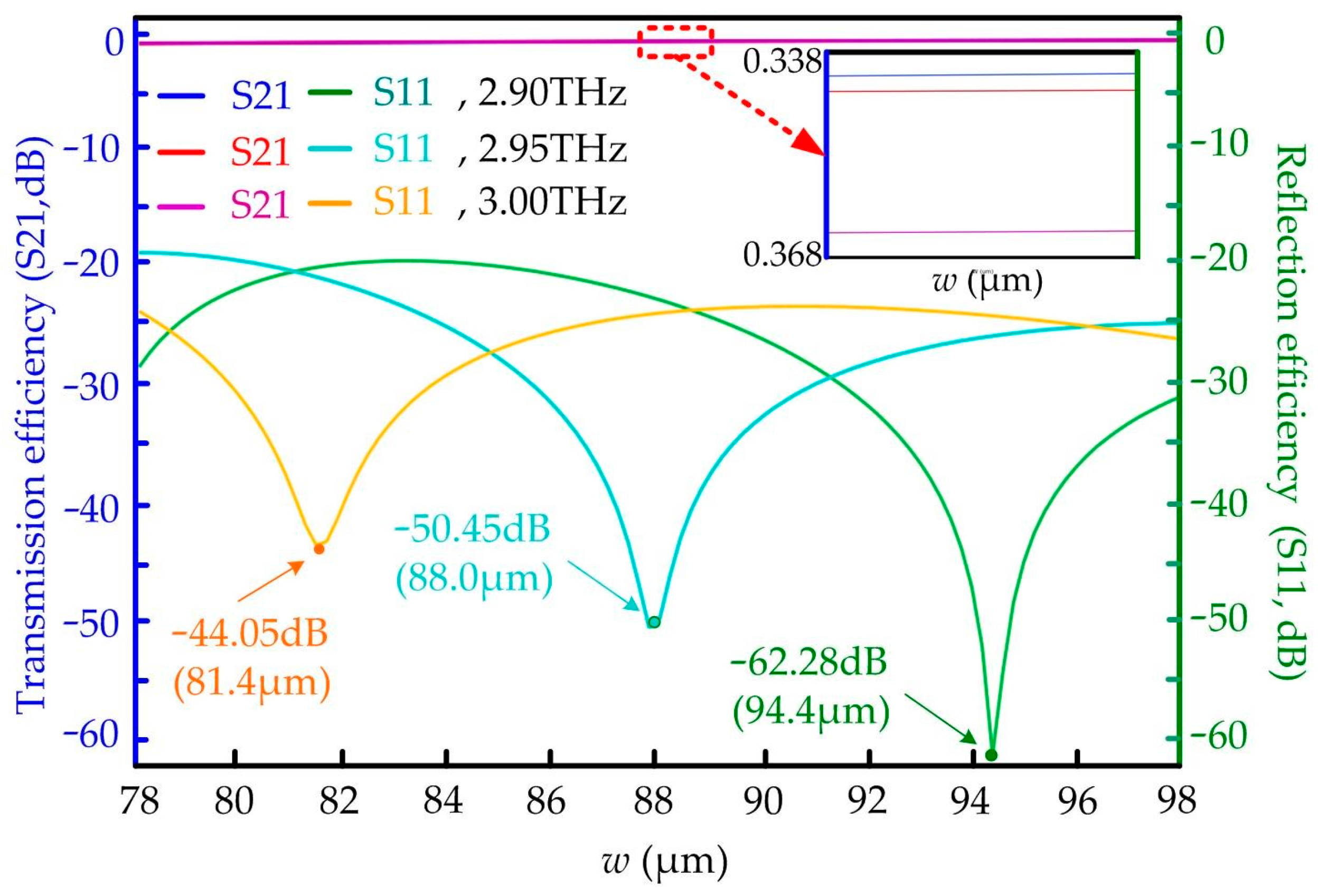
To optimize the external performance of the tellurium PhCs waveguide, the transmission efficiencies for TE mode with different widths are numerically investigated at some interesting certain frequencies of 2.90, 2.95, and 3.0 THz. When the width w of the waveguide increases from 78 to 98 μm, the curves of the S parameters for THz waves with different frequencies have a similar trend in Figure 8.
In Figure 8, both of the three curves for reflection efficiencies (S11) are first decreasing and then increasing with the changing width w, and the optimal reflection efficiency is always achieved at a certain width value. In detail, the minimum values of −44.05 dB, −50.45 dB, and −62.28 dB in the three solid-line curves with colors of yellow, cyan, and green are the lowest reflections for the THz transmission line at frequencies of 2.90 THz, 2.95 THz, and 3.00 THz, respectively.
The numerical results simultaneously indicate that the designed transmission line keeps fairly high efficiency for TE mode, with all the values of the width in the horizontal axis of Figure 8. The three curves for transmission efficiencies (S21) with the changing width w are close to coincidence. In the detailed diagram in Figure 8, the optimal transmission efficiencies of the tellurium PhCs waveguide remain above −0.368 dB. The three solid-line curves with colors of blue, red, and purple are the transmission efficiencies for the THz transmission line at frequencies of 2.90 THz, 2.95 THz, and 3.00 THz, respectively.
Through the above discussion, it is evident that tellurium PhCs not only have a doubtless complete PBG but that the THz transmission line consisting of the two tellurium rod arrays also has excellent transmission efficiency above −0.368 dB. The designed THz waveguide with its unique function and high performance provides a promising approach for implementing fully polarized THz devices like circulators [34] and isolators [35] for future communication systems.

5. Conclusions

In conclusion, a novel highly efficient THz fully polarized transmission line is designed by 2D tellurium PhCs consisting of two square lattice rod arrays with complete PBGs in this paper. The TE and TM PBGs of tellurium PhCs happen to coincide, which are calculated by PWEM, and the complete PBG covers from 2.894 to 3.025 THz. The function and transmission characteristics of the PhCs waveguide are simulated by FEM. The transmission efficiency of the transmission line is optimized by accurately adjusting its width. The transmission efficiency of the waveguide for TE mode achieves a maximum value of −0.34 dB at a central frequency of 2.950 THz and keeps above −3 dB from 2.82 THz to 3.02 THz, obtaining a broad relative bandwidth of about 6.84 percent. The operating bandwidth of the tellurium PhCs waveguide for TM mode is narrower than that of TE mode, whose relative bandwidth is about 4.39 percent around 2.936 THz above −5 dB. The designed terahertz photonic crystals waveguide can transmit both TE and TM waves, which can not only be used as a high-efficiency transmission line but also provides a promising approach for implementing fully polarized THz devices for future 6G communication systems.

Author Contributions

Conceptualization, W.H., S.Z. and W.W.; methodology, Y.W., L.F. and B.X.; software, Y.W., H.H. and X.L. (Xiaotong Liu); validation, Y.W., H.H., Z.Z. (Zhifeng Zeng), Y.L. and Z.Z. (Zhijian Zheng); formal analysis, Y.W., Z.Z. (Zhifeng Zeng), and K.Y.; investigation, Y.W., Y.L., K.Y. and W.W.; resources, W.H. and W.W.; data curation, Y.W., H.H., Z.Z. (Zhifeng Zeng), X.L. (Xingquan Li), and B.X.; writing—original draft preparation, Y.W., Y.L., L.F. and X.L. (Xingquan Li); writing—review and editing, Y.W., L.F. and Z.Z. (Zhijian Zheng); visualization, Y.W., X.L. (Xingquan Li), and B.X.; supervision, Y.W., Z.Z. (Zhijian Zheng), and W.W.; project administration, Y.W., X.L. (Xiaotong Liu), K.Y. and S.Z.; funding acquisition, Y.W., X.L. (Xiaotong Liu), W.H. and W.W. All authors have read and agreed to the published version of the manuscript.

Funding

This work was supported in part by the Foundation of the Shenzhen Institute of Information Technology (HX-0766, HX-0800, HX-0801) and the National Natural Science Foundation of China (61901277).

Data Availability Statement

Data is contained within the article.

Acknowledgments

The authors would like to acknowledge the Shenzhen Institute of Information Technology, Shenzhen Research Institute of Xidian University, and the College of Electronics and Information Technology of Shenzhen University. The authors also acknowledge the four students of Huifeng Su, Xinyu Fu, Shuochun Cai and Zhuozi Xu for their contributions to this work.

Conflicts of Interest

The authors declare no conflicts of interest.

References

  1. European Vision for the 6G Network Ecosystem. Available online: https://5g-ppp.eu/wp-content/uploads/2021/06/WhitePaper-6G-Europe.pdf (accessed on 7 June 2021).
  2. Chang, L.; Xie, W.; Shu, H.; Yang, Q.F.; Shen, B.; Boes, A.; Perters, D.; Jin, W.; Xiang, C.; Liu, S.; et al. Ultra-Efficient Frequency Comb Generation in AlGaAs-on-Insulator Microresonators. Nat. Commun. 2020, 11, 1331. [Google Scholar] [CrossRef]
  3. Shih, Y.; Silalahi, H.; Tsai, T.; Chen, Y.C.; Su, J.Y.; Lee, C.R.; Huang, C.Y. Optically Tunable and Thermally Erasable Terahertz Intensity Modulators Using Dye-Doped Liquid Crystal Cells with Metasurfaces. Crystals 2021, 11, 1580. [Google Scholar] [CrossRef]
  4. Jin, G.; Ren, Y.; Tang, B. Numerical Simulations of Circular Dichroism and Polarization Conversion in VO2-Based Terahertz Metamaterials. Crystals 2023, 13, 437. [Google Scholar] [CrossRef]
  5. Campion, J.; Xenidis, N.; Smirnov, S.; Ivanov, R.; Oberhammer, J.; Hussainova, I. Ultra-wideband integrated graphene-based absorbers for terahertz waveguide systems. Adv. Electron. Mater. 2022, 9, 8. [Google Scholar] [CrossRef]
  6. Ohlinger, K.; Lin, Y.; Qualls, J. Maximum and overlapped photonic band gaps in both transverse electric and transverse magnetic polarizations in two-dimensional photonic crystals with low symmetry. J. Appl. Phys. 2009, 106, 063520. [Google Scholar] [CrossRef]
  7. Xu, P.; Zhang, K.; Liu, H.; Li, R.; Li, L. Dual-band metasurface generating multiple OAM beams independently in full polarizations. Opt. Express 2023, 31, 32637–32651. [Google Scholar] [CrossRef] [PubMed]
  8. Wen, F.; David, S.; Checoury, X.; Kurdi, M.E.; Boucaud, P. Two-dimensional photonic crystals with large complete photonic band gaps in both TE and TM polarizations. Opt. Express 2008, 16, 12278–12289. [Google Scholar] [CrossRef]
  9. Ma, B.; Hao, R.; Yan, H.; Jiang, H.; Chen, J.; Tang, K. Deep learning-based inverse design of the complete photonic band gap in two-dimensional photonic crystals. Curr. Nanosci. 2023, 19, 423–431. [Google Scholar]
  10. Katyba, G.M.; Kurlov, V.N.; Zaytsev, K.I. Terahertz Photonic Crystal Waveguides Based on Sapphire Shaped Crystals. IEEE Trans. Terahertz Sci. Technol. 2016, 6, 576–582. [Google Scholar]
  11. Soltanian, M.; Amiri, I.S.; Alavi, S.E.; Ahmad, H. Dual-wavelength erbium-doped fiber laser to generate terahertz radiation using photonic crystal fiber. J. Light. Technol. 2015, 3, 5038–5046. [Google Scholar] [CrossRef]
  12. Liu, L.; Hesler, J.L.; Xu, H.; Lichtenberger, A.W.; Weikle, R.M. A broadband quasi-optical terahertz detector utilizing a zero bias schottky diode. IEEE Microw. Wirel. Compon. Lett. 2010, 20, 504–506. [Google Scholar] [CrossRef]
  13. Srinivasan, K.; Stadler, B.J.H. Review of integrated magneto-optical isolators with rare-earth iron garnets for polarization diverse and magnet-free isolation in silicon photonic. Opt. Mater. Express 2022, 12, 697–716. [Google Scholar] [CrossRef]
  14. Wei, Z.; Yan, W.; Qin, J.; Deng, L.; Bi, L. Dysprosium substituted Ce: YIG thin films for temperature insensitive integrated optical isolator applications. Materials 2022, 15, 1691. [Google Scholar] [CrossRef] [PubMed]
  15. Ghosh, S.; Keyvaninia, S.; Shirato, Y.; Mizumoto, T.; Roclkens, G.; Baets, R. Optical isolator for TE Polarized light realized by adhesive bonding of Ce:YIG on silicon-on-insulator waveguide circuits. IEEE Photonic J. 2013, 5, 6601108. [Google Scholar] [CrossRef]
  16. Tian, H.; Liu, J.; Siddharth, A.; Wang, R.; Blesin, T.; He, J.; Kippenberg, T.; Bhave, S.A. Magnetic-free silicon nitride integrated optical isolator. Nat. Photonics 2021, 15, 828–836. [Google Scholar] [CrossRef]
  17. Wang, Y.; Xu, B.G.; Zhang, D.G.; Xu, S.X.; Dong, Z.; Zeng, X.K.; Lu, X.W.; Pei, J.H. Magneto-optical isolator based on ultra-wideband photonic crystals waveguide for 5G communication. Crystals 2019, 9, 570. [Google Scholar] [CrossRef]
  18. Liu, W.; Liu, H.; Sun, X.; Zhang, F. The design of large curved waveguide based on sunflower graded photonic crystal. Photonics 2023, 10, 781. [Google Scholar] [CrossRef]
  19. Maleki, M.J.; Soroosh, M. A low-loss subwavelength plasmonic waveguide for surface plasmon polariton transmission in optical circuits. Opt. Quantum Electron. 2023, 55, 1266. [Google Scholar] [CrossRef]
  20. Noori, M.; Soroosh, M. A comprehensive comparison of photonic band gap and self-collimation based 2D square array waveguides. Optik 2015, 126, 4775–4781. [Google Scholar] [CrossRef]
  21. Lin, Y.; Che, D.; Hao, W.; Dong, Y.; Guo, H.; Wang, J.; Zhang, X. Controllable patterning of metallic photonic crystals for waveguide-plasmon interaction. Nanomaterials 2023, 13, 629. [Google Scholar] [CrossRef]
  22. Oliver, S.; Smith, C.; Rattier, M.; Benisty, H.; Weisbuch, C.; Krauss, T.; Hondre, R.; Oesterle, U. Miniband transmission in a hotonic crystal coupled-resonator optical waveguide. Opt. Lett. 2001, 26, 1019–1021. [Google Scholar] [CrossRef] [PubMed]
  23. Li, Z.Y.; Gu, B.Y.; Yang, G.Z. Large absolute band gap in 2D anisotropic photonic crystals. Phys. Rev. Lett. 1998, 81, 2574. [Google Scholar] [CrossRef]
  24. Fang, K.; Yu, Z.; Liu, V.; Fan, S. Ultracompact nonreciprocal optical isolator based on guided resonance in a magneto-optical photonic crystal slab. Opt. Lett. 2011, 36, 4254–4256. [Google Scholar] [CrossRef] [PubMed]
  25. Wang, P.Y.; Lai, Y.C.; Cheng, Y.C. Spatial beam filtering with auto-cloned photonic crystals. Crystals 2019, 9, 585. [Google Scholar] [CrossRef]
  26. Jao, R.F.; Lin, M.C. Quantitative analysis of photon density of states for one-dimensional photonic crystals in a rectangular waveguide. Crystals 2019, 9, 576. [Google Scholar] [CrossRef]
  27. Duan, S.Q.; Chen, Y.P.; Li, G.Z.; Zhu, C.Y.; Chen, X.F. Broadband polarization beam splitter based on a negative refractive lithium niobate photonic crystal slab. Chin. Opt. Lett. 2016, 14, 042301–042304. [Google Scholar] [CrossRef]
  28. Pligovka, A.; Poznyak, A.; Norek, M. Optical Properties of Porous Alumina Assisted Niobia Nanostructured Films–Designing 2-D Photonic Crystals Based on Hexagonally Arranged Nanocolumns. Micromachines 2021, 12, 589. [Google Scholar] [CrossRef] [PubMed]
  29. Xu, B.; Zhang, D.; Wang, Y.; Hong, B.; Shu, G.; He, W. A Terahertz Circulator Based on Magneto Photonic Crystal Slab. Photonics 2023, 10, 360. [Google Scholar] [CrossRef]
  30. Hasanuzzaman, G.; Rana, S.; Habib, M.S. A novel low loss, highly birefringent photonic crystal fiber in THz regime. IEEE Photonics Technol. Lett. 2016, 28, 899–902. [Google Scholar] [CrossRef]
  31. Fan, F.; Chang, S.J.; Niu, C.; Hou, Y.; Wang, X.H. Magnetically tunable silicon ferrite photonic crystals for terahertz circulator. Opt. Commun. 2012, 285, 3763–3769. [Google Scholar] [CrossRef]
  32. Wang, Y.; Zhang, D.G.; Xu, B.G.; He, W.L.; Ian, H. Ultra-wideband terahertz circulator with a ferrite-sphere filled triangle photonic crystal. Mater. Sci. Eng. B 2022, 277, 115603. [Google Scholar] [CrossRef]
  33. Wang, Y.; Zhang, D.G.; Xu, B.G.; Dong, Z.; Zeng, X.K.; Pei, J.H.; Xu, S.X.; Xue, Q. Four ports double Y-shaped ultra-wideband magneto-photonic crystals circulator for 5G communication system. IEEE Access 2019, 7, 120463–120474. [Google Scholar] [CrossRef]
  34. Dmitriev, V.; Portela, G.; Martins, L. Photonic crystal-based circulators with three and four ports for sub-terahertz region. Photonic Netw. Commun. 2017, 33, 303–312. [Google Scholar] [CrossRef]
  35. Wang, Y.; Xu, B.G.; Chang, K.; Huang, H.; Xu, Z.; He, W.; Wang, W. Band Broadening of Terahertz Photonic Crystals Circulator Using Two Symmetrical Hexagonal Aluminum Sheets. Crystals 2023, 13, 779. [Google Scholar] [CrossRef]
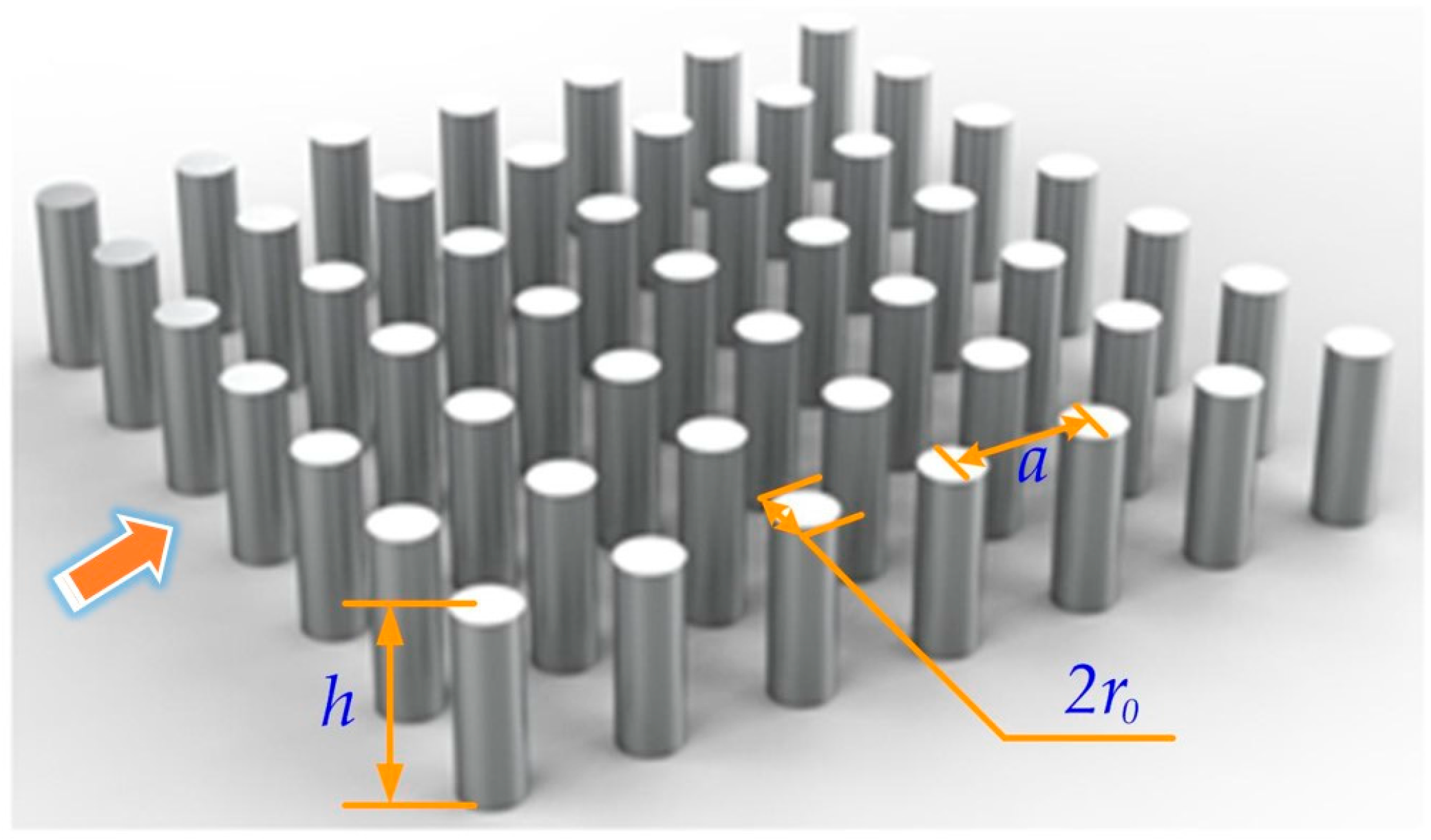
Figure 1. Two-dimensional square lattice PhCs with 7 × 7 tellurium rods array.
Crystals 14 00518 g001
Figure 2. (a) The plane graph of the 7 × 7 square lattice tellurium rods array; (b) the details of the Brillouin zone and Kpath.
Crystals 14 00518 g002
Figure 3. The PBGs of TE and TM modes for tellurium PhCs with increasing r0: (a) the PBG of TE mode; (b) the PBG of TM mode.
Crystals 14 00518 g003
Figure 4. The plane graph of the PhCs fully polarized waveguide.
Crystals 14 00518 g004
Figure 5. (a) The distribution of the amplitude Ez for TE mode at 2.950 THz; (b) the distribution of the amplitude Hz for TM mode at 2.950 THz.
Crystals 14 00518 g005
Figure 6. (a) The transmission efficiency of the PhCs waveguide with the frequency for TE mode; (b) the transmission efficiency of the PhCs waveguide with the frequency for TM mode.
Crystals 14 00518 g006
Figure 7. The power distributions of the THz signals with different frequencies for TE and TM modes: (a) TE mode at 2.850 THz; (b) TE mode at 2.90 THz; (c) TE mode at 2.950 THz; (d) TE mode at 3.0 THz; (e) TE mode at 3.050 THz; (f) TM mode at 2.850 THz; (g) TM mode at 2.90 THz; (h) TM mode at 2.950 THz; (i) TM mode at 3.0 THz; (j) TM mode at 3.050 THz.
Crystals 14 00518 g007
Figure 8. The transmission and reflection efficiencies of the tellurium PhCs waveguide with increasing width w at frequencies of 2.90, 2.95, and 3.0 THz.
Crystals 14 00518 g008
Table 1. The comparison table on the following parameters between our results and the literature.
LiteratureWavelengthTransmissionInsertion Loss
[18]0.85, 1.31, 1.55 μmabove 90 percentLess than 10 percent
[19]6 to 9.4 μmabove 93.5 percent0.029 dB/μm
[20]1.55 μmabove 90 percentLess than 10 percent
Our data101.7 μmabove 92.5 percent0.34 dB
Disclaimer/Publisher’s Note: The statements, opinions and data contained in all publications are solely those of the individual author(s) and contributor(s) and not of MDPI and/or the editor(s). MDPI and/or the editor(s) disclaim responsibility for any injury to people or property resulting from any ideas, methods, instructions or products referred to in the content.