Article

Molecular Dynamics Study of the Deformation Behavior and Strengthening Mechanisms of Cu/Graphene Composites under Nanoindentation

1
College of Automotive and Mechanical Engineering, Changsha University of Science and Technology, Changsha 410114, China
2
Hunan Key Laboratory of Super Microstructure and Ultrafast Process, School of Physics and Electronics, Central South University, Changsha 410083, China
3
Science and Technology on Ballistic Missile Penetration Laboratory, Beijing 100076, China
4
National Engineering Research Center for Mechanical Product Remanufacturing, Army Academy of Armored Forces, Beijing 100072, China
*
Authors to whom correspondence should be addressed.
Crystals 2024, 14(6), 525; https://doi.org/10.3390/cryst14060525
Submission received: 10 May 2024 / Revised: 28 May 2024 / Accepted: 29 May 2024 / Published: 31 May 2024
(This article belongs to the Section Crystalline Metals and Alloys)

Abstract

:
The mechanical performance of pure copper can be significantly strengthened by adding graphene without greatly sacrificing its electrical and thermal conductivity. However, it is difficult to observe the deformation behavior of Cu/graphene composites efficiently and optically using experiments due to the extremely small graphene size. Herein, Cu/graphene composites with different graphene positions and layers were built to investigate the effect of these factors on the mechanical performance of the composites and the deformation mechanisms using molecular dynamics simulations. The results showed that the maximum indentation force and hardness of the composites decreased significantly with an increase in the distance from graphene to the indentation surface. Graphene strengthened the mechanical properties of Cu/graphene composites by hindering the slip of dislocations. As the graphene layers increased, the strengthening effect became more pronounced. With more graphene layers, dislocations within the Cu matrix were required to overcome higher stress to be released towards the surface; thus, they had to store enough energy to allow more crystalline surfaces to slip, resulting in more dislocations being generated.

1. Introduction

Pure copper has great thermal and electrical conductivity, while its low strength limits its engineering applications. Thus, there is a need to improve copper strength without destroying its original properties [1,2]. An effective method is to add appropriate stronger materials into pure copper to form a composite material, such as ceramic particles, fibers and graphene. Typically, graphene is an excellent strengthening materials due to its high fracture strength, electrical conductivity, ductility and Young’s modulus [3,4,5].
Adding graphene into pure copper improves its material strength through microstructural refinement, dislocation pinning and the interaction of dislocations within the Cu matrix with the copper/graphene (Cu/gr) interfaces [6,7]. Meanwhile, graphene and Cu particles form a grain boundary phase during the sintering process, which disperses the charge carriers near the grain boundaries, resulting in a small sacrifice of the Cu electrical conductivity [8,9]. However, the deformation of graphene is difficult to capture experimentally because of its extremely small size. Molecular dynamics (MD) simulations can clearly clarify the evolution of a microstructure and dislocations during deformation. At present, most MD simulation studies on Cu/gr composites focus mainly on their physical and mechanical properties. For example, Kazakov et al. [10] investigated the thermal conductivity of Cu/gr composites based on MD simulations and found that the thermal conductivity decreases with an increase in the number of graphene layers. Guo et al. [11] compared crack extension in single-crystal copper and copper/graphene composites using MD simulations, and found that the incorporation of graphene was beneficial in suppressing crack extension. Xu et al. [12] investigated the effect of graphene on the arc erosion resistance of Cu using MD simulations. The results showed that the graphene layer can dissipate the energy transferred by the incident ions through the shock wave and prevent the recoiling Cu atoms from penetrating into the graphene layer, which produces a better arc erosion performance than the pure Cu system. Weng et al. [13] performed molecular dynamics simulations of nanolaminated graphene/Cu and pure Cu under compression to investigate the strengthening mechanism of graphene and the effect of flake thickness. Although many studies have been carried out on the physical and mechanical properties of Cu/gr composites, the understanding of their plastic deformation behavior under nanoindentation behavior is still lacking. Compared to macroscopic experimental characterization, nanoindentation experiments can study the deformation behavior of Cu/gr composites at the micro/nanoscale. Wang et al. [14] investigated the nanoindentation behavior at the Cu/multilayer graphene interface boundary (IB) region. Although the deformation of graphene can be partially observed by nanoindentation experiments, it is still difficult to clearly visualize the interaction of dislocations, stacking faults and twins with the Cu/gr interfaces. Therefore, many researchers have used MD simulations to study the nanoindentation behavior of the Cu/gr composites. Peng et al. [15,16] investigated the effect of a graphene coating on plastic copper deformation under different indentation conditions. They found the graphene coating significantly enhances the load-bearing capacity of the Cu substrate for displacement-controlled indentation, which is directly correlated to the increase in graphene layers. Unfortunately, MD research on the effect of graphene position on the deformation behavior of Cu matrix is rare. In addition, graphene in Cu/gr composites often consists of many layers that are stacked together, so it is more significant to study the effect of graphene layers on Cu/graphene composites. More importantly, there is a lack of systematic illustration and a lack of summaries of the effects that the distribution positions and layers of graphene inside the Cu matrix have on the strengthening mechanisms of Cu/gr composites. Revealing the effects of these factors on Cu/gr composites is crucial to optimize the performance of the composites.
Herein, the mechanical performance and plastic deformation mechanism of Cu/gr composites were investigated via molecular dynamics (MD) simulations of nanoindentation in different graphene positions and with different numbers of layers.

2. Simulation Method

In this paper, a microscopic evolution of defects in Cu/gr composites during nanoindentation was simulated via the MD simulation method using LAMMPS, and the effects of graphene position and graphene layer number on Cu/gr composites were investigated. Figure 1 shows a diagram of the Cu/gr composite nanoindentation model with total lengths of 18 × 18 × 10 nm3. d is the distance between the graphene layer and Cu matrix surface. The orientation of the Cu matrix is x-[100], y-[010] and z-[011].
In this work, the C-C interaction force was determined via the adaptive intermolecular reactive empirical bond order (AIREBO) potential [17], and the classical embedded atom method (EAM) proposed by S.M. Foiles et al. [18] was employed to define the interactions between Cu atoms. Furthermore, the Lennard–Jones (L-J) potential was adopted to describe the interactions between C and Cu atoms ( ε C u C = 0.02578   e V , δ C u C = 3.0825   Å ). The feasibility of this L-J potential function has been demonstrated in [19,20].
In the simulations, to ensure the stability of the structure, the boundary atomic layer of 0.5 nm thickness was retained. An intermediate thermostatic atomic layer of 0.5 nm thickness was adjacent to the boundary atomic layer, which was kept constant at the simulated temperature via a velocity scaling procedure. To eliminate temperature effects, the temperature of this simulation was controlled at 10 K. The virtual indenter created the repulsive ball, and the interaction potential between the tip of the indenter and the model atoms was determined as follows:
F r = K R r 2 , r > R 0 , r < R
where R is the radius of the indenter with the value of 3.5 nm, r denotes the distance from the atoms in the substrate to the indenter and the indenter stiffness K is fixed to 10   e V / Å 3 . To facilitate the calculation, the indentation speed v was set to 10   m / s . The indenter entered the composite surface vertically with a final depth of 30 Å. Finally, the microstructure evolution and dislocation motion of the material were analyzed using the visualization software OVITO Basic [21].

3. Results and Discussion

3.1. Effect of Graphene Position on Cu/gr Composites

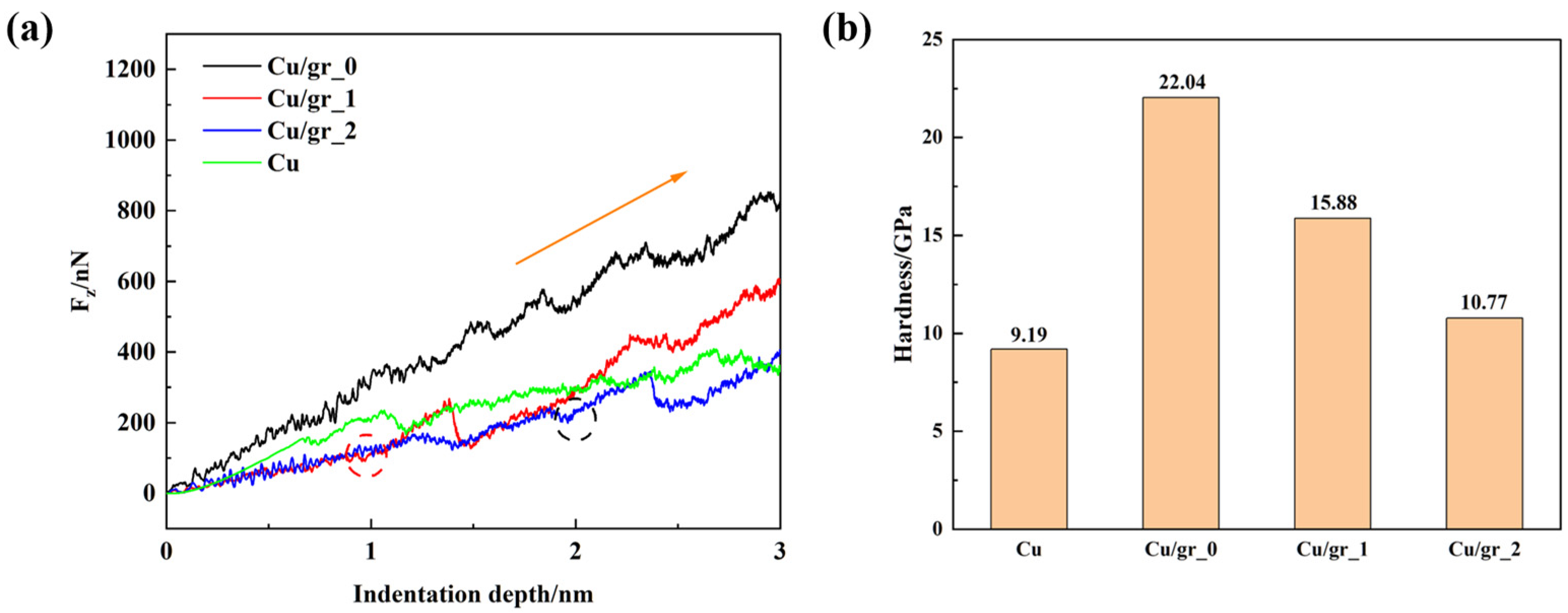
3.1.1. Mechanical Performance

To explore the effect of graphene positions on the mechanical performance of Cu/Gr composites, we built three composites with different graphene positions, as shown in Figure 1. The distances from the graphene to the upper matrix surface (indentation surface) d were 0   n m , 1   n m and 2   n m , respectively, as shown in Figure 2. We defined the corresponding composites as Cu/gr_0, Cu/gr_1 and Cu/gr_2, respectively. In addition, a model of pure Cu was built for comparison.
Figure 3a shows the indentation curves of Cu/gr composites at different graphene positions with pure copper. Compared with pure Cu, the indenting force of Cu/gr_0 was higher at all indenting depths, while the indenting force of Cu/gr_1 and Cu/gr_2 was lower at the early indented stage. When the indentation depth reached 1   n m , the indenter started to indent the graphene in Cu/gr_1, which led to the indentation force of Cu/gr_1 starting to increase rapidly, as shown by the red circle in Figure 3a. When the indentation depth reached 2   n m , the indentation force of Cu/gr_2 appeared to be the same as that of Cu/gr_1 (as shown in the black circle in Figure 3a). Furthermore, when the indentation depth reached 3   n m , the indentation forces of the Cu/gr composites all exceeded that of pure Cu.
Hardness reflects the ability of a material to resist the pressure of a hard object on its surface. In the nanoindentation process, the hardness H can be calculated by the following equation [22,23]:
H = F m a x A c
where F m a x is the maximum force during indentation and A c is the contact area, which can be expressed as [24]:
A c = π 2 R h h
where h is the indentation depth and R is the radius of the spherical indenter.
Figure 3b shows the hardness of Cu/gr composites and pure Cu at different graphene positions during the indentation process. It was seen that Cu/gr composites were higher in hardness than pure Cu, which further indicated that graphene could significantly strengthen the mechanical properties of the Cu matrix. It was noteworthy that the smaller the vertical distance from graphene to the indentation surface, the higher the hardness of the Cu/gr composites. This agrees with the experimental results of Wang et al. [14].

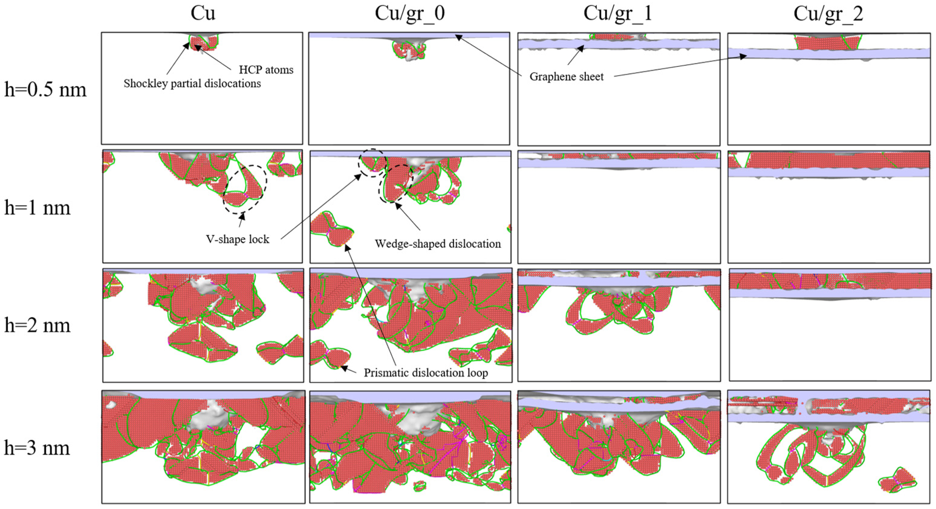
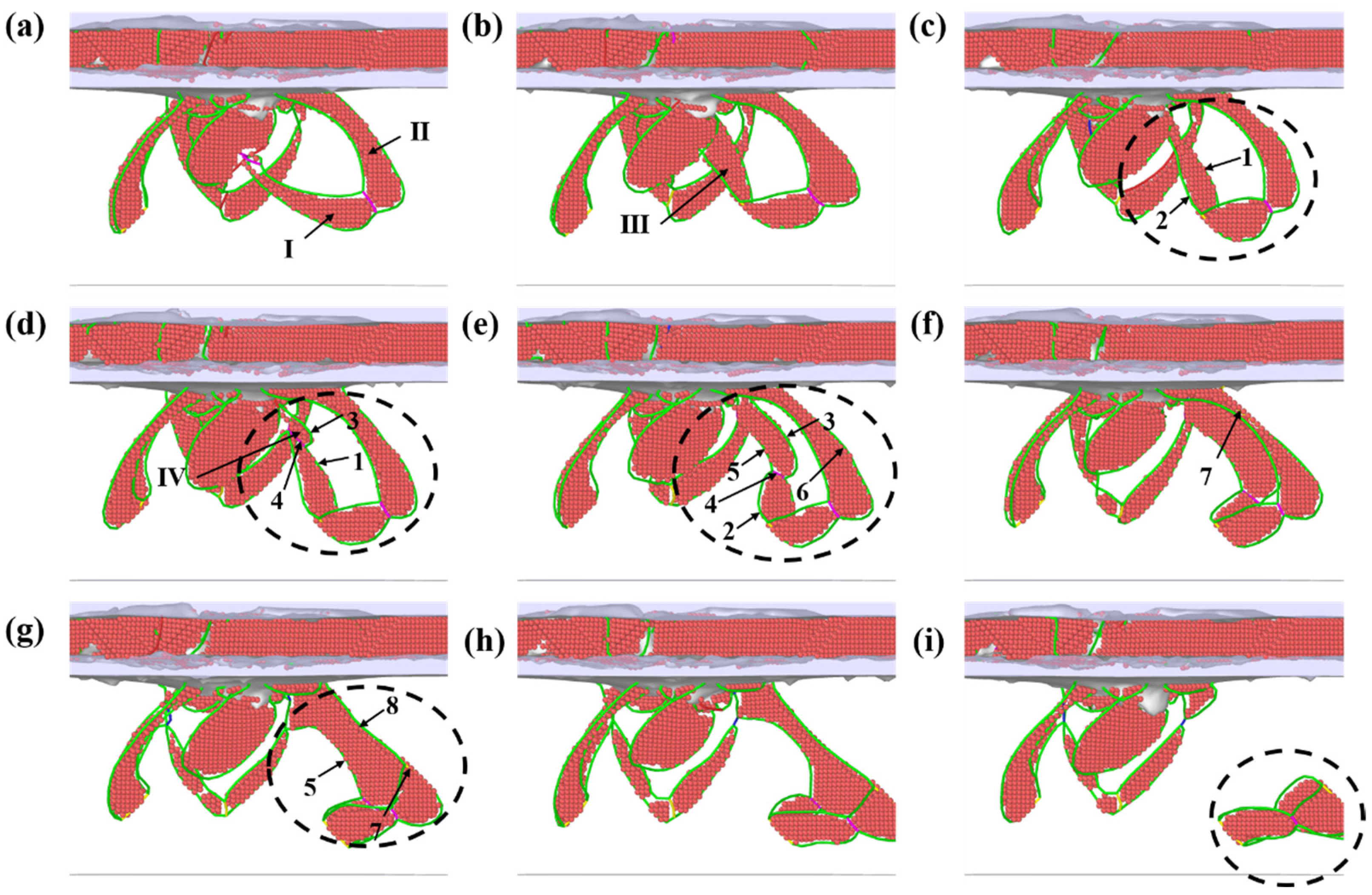
3.1.2. Plastic Deformation Behavior

In order to understand the deformation behavior of Cu/Gr composites, the evolution of dislocations and structure during nanoindentation are presented in Figure 4. When the indentation depth reached 0.5   n m , the dislocations started to nucleate. Firstly, the Shockley partial dislocations (SPDs) were generated near the contact tip, and the FCC atoms in this region were transformed into HCP atoms. It was noteworthy that the indenter did not touch the graphene layer at this time because the graphene of Cu/gr_1 and Cu/gr_2 was located 1 nm and 2 nm from the indentation surface, respectively. The dislocations cannot expand downward through the graphene throughout this process, but gather at the top of the graphene layer, which indicates that graphene had a hindering effect on dislocation slip [25]. As the indentation depth increased and the indenter pressed into the graphene, dislocations were generated at the bottom of the graphene. Furthermore, these dislocations were closely stacked, resulting in wedge-shaped dislocation surfaces. As the indentation was further deepened, the wedge-shaped dislocation surfaces crossed each other and combined to form V-shaped locked defect structures. In addition, the V-shaped locked defects without fracture were transformed into dislocation loops. When the maximum indentation depth was reached, a dislocation network of numerous dislocations was formed under the graphene, and these dislocations were stacked and entangled with each other, acting as a form of dislocation reinforcement.
To further illustrate the process of dislocation loop nucleation, the atomic structures in Cu/gr_2 with different indentation depths are shown in Figure 5. Firstly, the dislocation loop was nucleated on dislocation surface I and dislocation surface II (as shown in Figure 5a). As the indentation continued, new dislocation surfaces began to nucleate and grow. Dislocation surface I and the newly generated dislocation surface III were close to each other and gradually came into contact, forming a ‘lasso’-like dislocation ring (as shown by the black dashed circle in Figure 5b). As the indenter continued to penetrate deeper, more new dislocations were nucleated in the Cu matrix. The Shockley partial dislocation 1 gradually interacted with the newly generated Shockley partial dislocation 3 according to Equation (4) to form a new stair-rod dislocation 4, leading to the nucleation of a new dislocation surface IV, as shown in Figure 5d. Dislocation surface IV continued to grow until Shockley partial dislocation 2 and stair-rod dislocation 4 approached each other and reacted according to Equation (5) to form a new Shockley partial dislocation 5. Shockley partial dislocation 3 continued to approach Shockley partial dislocation 6, and eventually these two dislocations met and formed a new Hirth dislocation 7, which caused the combination of dislocation surface II and dislocation surface IV, thus forming a new dislocation surface, as shown in Figure 5g. Finally, Shockley partial dislocation 5 contacted with Shockley partial dislocation 8, and eventually these two dislocations were annihilated, as shown by Equation (7). This resulted in dislocations to pinch off, eventually evolveding into an independent dislocation loop, as shown in Figure 5i. The dislocation loop nucleation process described above is similar to that described by Hua et al. [26].
The dislocation reaction described above is shown below:
1 + 3 = 4   :   1 6 1 ¯ 1 2 ¯ + 1 6 2 1 ¯ 1 = 1 6 10 1 ¯
2 + 4 = 5   :   1 6 2 ¯ 1 ¯ 1 ¯ + 1 6 10 1 ¯ = 1 6 1 ¯ 1 ¯ 2 ¯
3 + 6 = 7   :   1 6 2 1 ¯ 1 + 1 6 2 ¯ 1 ¯ 1 ¯ = 1 3 0 1 ¯ 0
5 + 8 = 0   :   1 6 1 ¯ 1 ¯ 2 ¯ + 1 6 112 = 0
In order to better understand the dislocation loop in Cu/gr composites, the dislocation loop structure was separated, as shown in Figure 6a, and the Burgers vector of the dislocations is presented in Figure 6b. Three types of dislocations were present in the dislocation loop: Shockley dislocation, Hirth dislocation and stair-rod dislocation. The dislocation loop was an independent and closed dislocation line that could not expand inside the matrix, but it could move inside as the deformation proceeded.
Figure 7 shows the shear strain distribution of the Cu/gr composites and pure Cu when indentation depth h reached 3   n m during the indentation. The dark red color indicates high stress and dark blue indicates low stress based on local shear strain values. The Cu/gr composites had higher local stress values due to the lattice and shear modulus discrepancies between the Cu matrix and graphene [27,28]. In addition, as the graphene gradually approached the surface of the matrix, it not only facilitated the uniform distribution of the stress in the Cu matrix but also greatly strengthened the indentation resistance of the materials.

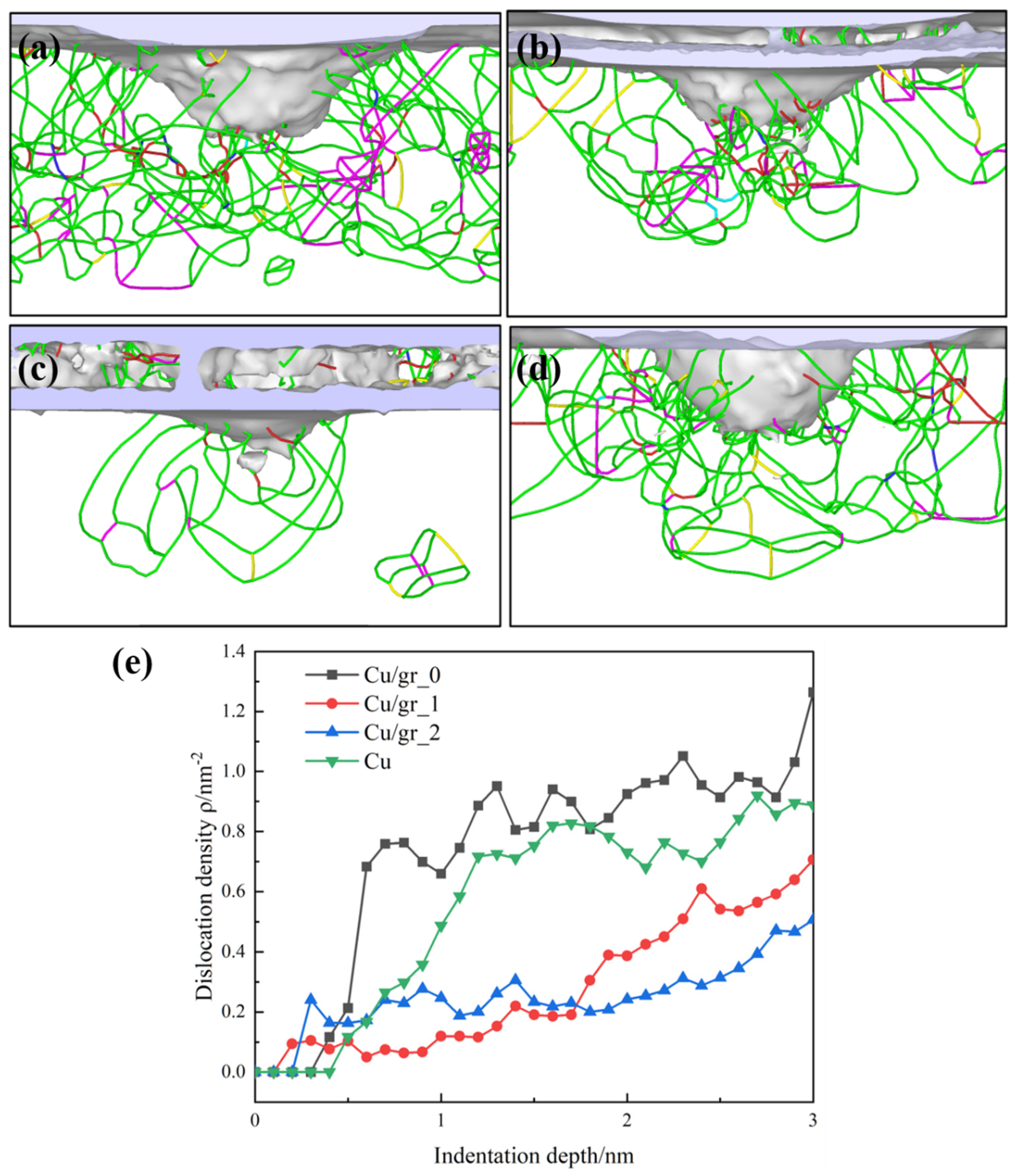
3.1.3. Dislocation Density

During the nanoindentation process, dislocations were mainly generated in the plastic deformation zone. The indentation area and the entire plastic deformation area were assumed to be hemispherical. An indentation depth h caused by a spherical indenter of radius R is shown in Figure 8 according to classical Hertzian contact theory.
The contact radius a c is described as [29]:
a c = R 2 ( R h ) 2
The dislocation density in the plastic deformation area could be calculated using the following equation [30,31]:
ρ = L d V p l
where L d is the total dislocation length and V p l is the volume of the plastic deformation area, which could be defined as [32,33]:
V p l = 2 π 3 R p l 3 V i n d
where R p l is the radius of the plastic deformation zone and V i n d is the volume of the indenter that is presently penetrating the matrix, which could be approximated as [32,33]:
V i n d = π h 2 R h 3
Generally, R p l represents the distance between the indenter tip and the furthest dislocation in a plastically deformed zone and can be easily obtained through analyzing the MD nanoindentation simulation results [34]. The dislocation density ρ of Cu/gr composites and pure Cu could be calculated in combination with Equations (9)–(11). The dislocation distributions of Cu/gr_0, Cu/gr_1, Cu/gr_2 and pure Cu at the indentation depth h up to 3 nm, and the dislocation density of Cu/gr composites and pure Cu at different graphene positions, are shown in Figure 9a,b,c,d and e, respectively. And the blue line represents complete dislocations, green line represents Shockley dislocations, yellow line represents Hirth dislocations, pink line represents stair-rod dislocations, light blue line represents Frank dislocations, red line represents other dislocations in Figure 9a–d. The dislocation density ρ increased with the increasing indentation depth h . At the early stage of indentation, the dislocation density slowly increased. When the indentation depth h reached about 0.5 nm, the dislocation density of pure Cu and Cu/gr_0 started to increase rapidly. However, the dislocation density of Cu/gr_1 and Cu/gr_2 does not change significantly due to the blocking effect of graphene on dislocations, preventing them from extending further into the Cu matrix. When the indentation depth h reached 1 nm, the indenter touched and gradually penetrated the graphene of Cu/gr_1. At this point, the dislocation density of Cu/gr_1 began to increase rapidly. When the indentation depth h reached 2 nm, the dislocation density of Cu/gr_2 started to increase quickly. Notably, the closer the graphene was to the indentation surface, the higher the dislocation density of Cu/gr composites.

3.2. Effect of Graphene Layers on Cu/gr Composites

3.2.1. Mechanical Performance

Three models of Cu/gr composites with different graphene layers were established to explore the effect of graphene layers on the mechanical performance of Cu/gr composites, as shown in Figure 10. The corresponding composites were called Cu/gr1, Cu/gr2 and Cu/gr3, and Cu/gr1 was the same model as Cu/gr_0, presented above. Similarly, a model of pure Cu was also established for comparison.
Figure 11a shows the indentation force–depth curves of Cu/gr composites and pure Cu under the nanoindentation simulation. As is shown, the corresponding indentation force F z gradually increased with the increase in graphene layers. The hardness of the Cu/gr composites and pure Cu with different graphene layers was calculated using the above hardness calculation equation, as shown in Figure 11b. The results implied that increasing the number of graphene layers could effectively strengthen the hardness of Cu/gr composites, and previous works have also shown similar results [35]. In addition, the increase in the number of graphene layers could also be interpreted as an increase in the graphene content. The results of nanoindentation experiments by Nidhi Khobragade et al. [36] showed that the hardness and Young’s modulus of the Cu/gr composites increase with increasing graphene content, which was consistent with the results of this simulation. The simulated values tend to differ significantly from the experimental values. This is due to the short duration of the MD simulation, which was loaded at a much higher rate than the experimental loading rate. If the trend of the simulation was consistent with the experiment, this could explain the mechanism of this experiment to a certain extent.

3.2.2. Plastic Deformation Behavior

The evolution of dislocations and structure during nanoindentation was observed to explore the effect of graphene layers on the microstructure evolution of Cu/gr composites, as shown in Figure 12. The results indicated that when the indentation depth h reached 3   n m , the main microstructures of the Cu/gr composites and pure Cu were very similar, with many dislocations and stacking faults appearing below the indenter, resulting in a dense dislocation network. It was noteworthy that no dislocations were generated in Cu/gr3 at h = 0.5   n m ; this indicates that Cu/gr3 was still in the elastic phase. In addition, the dislocation loops in Cu, Cu/gr1 and Cu/gr2 started to break off and form independent dislocation loops as the indentation progressed. However, most dislocation loops in Cu/gr3 will not move outward as the indentation progresses.
Figure 13 shows the shear strain distributions of Cu/gr composites and pure Cu under the nanoindentation simulation. When the indenter was pressed into the Cu matrix, a large amount of stress was generated under the indenter. Furthermore, as the indentation depth increased, the stress was transferred to the interior of the Cu matrix. During the indentation of pure Cu, the dislocations easily moved to the surface and were released, resulting in the accumulation of Cu atoms on the surface, as indicated by the red circle in Figure 13d. With the addition of graphene, the dislocations inside the Cu matrix must overcome greater stress to be released to the surface, significantly increasing the indentation resistance of the Cu/gr composites. Comparing the atomic structure of Figure 12, more dislocations and stacking faults were produced in Cu/gr composites than in pure Cu, and the dense three-dimensional dislocation network prevented further dislocations from spreading, thus stabilizing the plastic zone [37]. In addition, as the number of graphene layers increased, the dislocation network became concentrated and focused.

3.2.3. Dislocation Density

The dislocation distributions of Cu/gr1, Cu/gr2, Cu/gr3 and pure Cu at an indentation depth h up to 3   n m and the corresponding dislocation density are shown in Figure 14. The dislocations were nucleated approximately at the indentation depth h up to 0.5   n m , and the dislocation density ρ rapidly increased as the indentation proceeded. In addition, the dislocation density increased with the number graphene layers. This was because the Cu/gr composites with more graphene layers had a higher indentation resistance, which stored enough energy to allow for more crystalline surfaces to slip, resulting in the generation of more dislocations.

4. Conclusions

In this work, the plastic deformation behavior and strengthening mechanisms of Cu/Gr composites during nanoindentation were investigated via MD simulations, and the effect of graphene position and graphene layers was discussed. These results can provide a reference for the design of high-performance Cu/gr composites. They are presented as follows:
(1)
The maximum pressure and hardness of Cu/gr composites during nanoindentation significantly decreased as the distance from graphene to the indentation surface increased. The incorporation of graphene had a more significant strengthening effect.
(2)
During the indentation process, a denser network of dislocations was produced below the Cu/Gr interface than in pure Cu to effectively impede the movement of the dislocations, which is the main reason why the incorporation of graphene was able to strengthen the Cu/Gr composites.
(3)
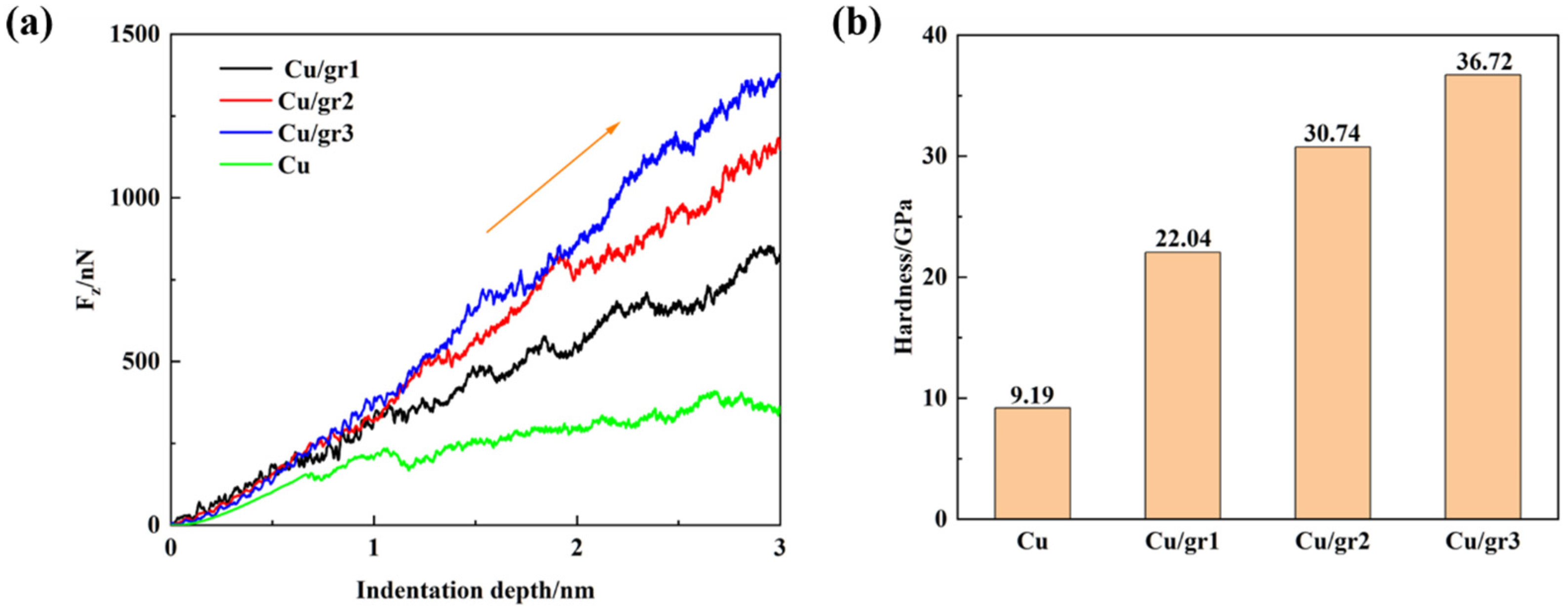
The maximum pressure and hardness of Cu/gr composites significantly increased with the number of graphene layers during nanoindentation. In addition, the high-shear-strain atomic region also increased with the graphene layers.
(4)
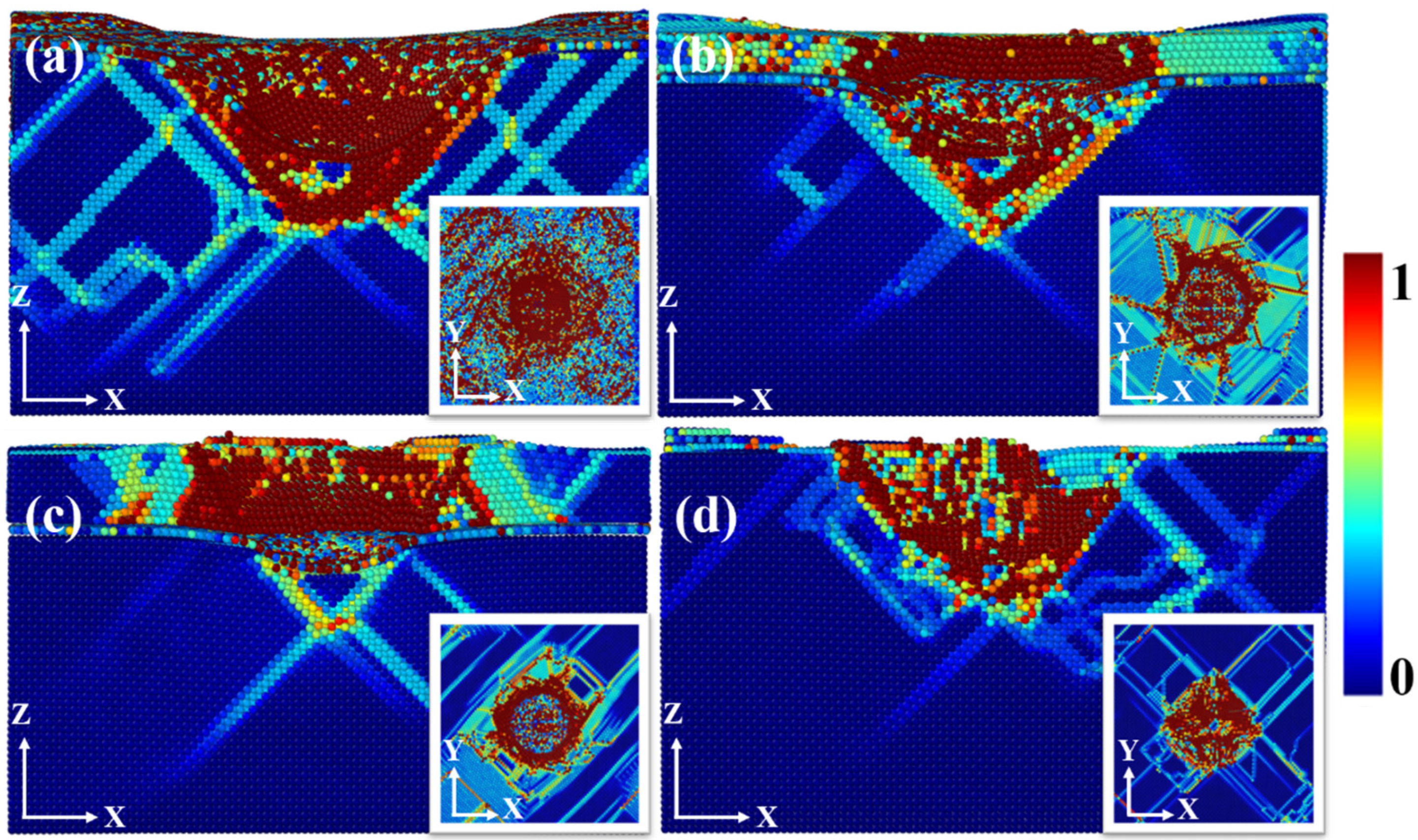
During the indentation process, the loading was transferred directly to the graphene reinforcement through the Cu/gr interface, which made the stress in graphene significantly larger than that in the Cu matrix, and this fully exploited the advantages of the high strength of graphene.

Author Contributions

Conceptualization, G.R., Y.W., M.Z. and Y.T.; methodology, G.R. and Y.L.; validation, C.Z.; formal analysis, G.R., Y.H. and J.L.; investigation, Y.W., Y.H. and J.F.; resources, L.W.; data curation, C.Z.; writing—original draft preparation, C.Z.; writing—review and editing, G.R. and Y.T.; visualization, J.F. All authors have read and agreed to the published version of the manuscript.

Funding

This work was supported by National Natural Science Foundation of China (No. 92166105 and 52005053), The Science and Technology Innovation Program of Hunan Province (No. 2021RC3096), Natural Science Foundation of Hunan Province (No. 2023JJ30038), and Scientific Research Program of Hunan Provincial Department of Education (No. 23A0264).

Data Availability Statement

The data presented in this study are available on request from the corresponding author due to privacy.

Conflicts of Interest

The authors declare no conflicts of interest.

References

  1. Cui, L.; Luo, R.; Wang, L.; Luo, H.; Deng, C. Novel copper-impregnated carbon strip for sliding contact materials. J. Alloys Compd. 2018, 735, 1846–1853. [Google Scholar] [CrossRef]
  2. Mazloum, A.; Kováčik, J.; Zagrai, A.; Sevostianov, I. Copper-graphite composite: Shear modulus, electrical resistivity, and cross-property connections. Int. J. Eng. Sci. 2020, 149, 103232. [Google Scholar] [CrossRef]
  3. Lee, C.; Wei, X.; Kysar, J.W.; Hone, J. Measurement of the elastic properties and intrinsic strength of monolayer graphene. science 2008, 321, 385–388. [Google Scholar] [CrossRef] [PubMed]
  4. Tjong, S.C. Recent progress in the development and properties of novel metal matrix nanocomposites reinforced with carbon nanotubes and graphene nanosheets. Mater. Sci.Eng. R Rep. 2013, 74, 281–350. [Google Scholar] [CrossRef]
  5. Wei, W.; Song, Y.; Yang, Z.; Gao, G.; Xu, P.; Lu, M.; Tu, C.; Chen, M.; Wu, G. Investigation of the impacts of thermal shock on carbon composite materials. Materials 2019, 12, 435. [Google Scholar] [CrossRef] [PubMed]
  6. Kim, Y.; Lee, J.; Yeom, M.S.; Shin, J.W.; Kim, H.; Cui, Y.; Kysar, J.W.; Hone, J.; Jung, Y.; Jeon, S. Strengthening effect of single-atomic-layer graphene in metal–graphene nanolayered composites. Nat. Commun. 2013, 4, 2114. [Google Scholar] [CrossRef] [PubMed]
  7. Wang, J.; Li, Z.; Fan, G.; Pan, H.; Chen, Z.; Zhang, D. Reinforcement with graphene nanosheets in aluminum matrix composites. Scr. Mater. 2012, 66, 594–597. [Google Scholar] [CrossRef]
  8. Gao, X.; Yue, H.; Guo, E.; Zhang, H.; Lin, X.; Yao, L.; Wang, B. Mechanical properties and thermal conductivity of graphene reinforced copper matrix composites. Powder Technol. 2016, 301, 601–607. [Google Scholar] [CrossRef]
  9. Rafiee, M.A.; Rafiee, J.; Wang, Z.; Song, H.; Yu, Z.-Z.; Koratkar, N. Enhanced mechanical properties of nanocomposites at low graphene content. ACS Nano 2009, 3, 3884–3890. [Google Scholar] [CrossRef]
  10. Kazakov, A.M.; Korznikova, G.F.; Tuvalev, I.I.; Izosimov, A.A.; Korznikova, E.A. The Effect of Copper–Graphene Composite Architecture on Thermal Transport Efficiency. Materials 2023, 16, 7199. [Google Scholar] [CrossRef]
  11. Guo, J.; Wang, B.; Yang, Z. Molecular dynamics simulations on the mechanical properties of graphene/Cu composites. Acta Mater. Compos. Sin. 2014, 31, 152–157. [Google Scholar]
  12. Xu, R.; Zhou, M.; Wang, X.; Matharage, S.Y.; Yan, J.D.; Connolly, A.; Luo, Y.; Ding, Y.; Wang, Z. A molecular dynamics simulation study on the role of graphene in enhancing the arc erosion resistance of Cu metal matrix. Comput. Mater. Sci. 2022, 212, 111549. [Google Scholar] [CrossRef]
  13. Weng, S.; Ning, H.; Fu, T.; Hu, N.; Zhao, Y.; Huang, C.; Peng, X. Molecular dynamics study of strengthening mechanism of nanolaminated graphene/Cu composites under compression. Sci. Rep. 2018, 8, 3089. [Google Scholar] [CrossRef] [PubMed]
  14. Wang, X.; Su, Y.; Han, S.; Crimp, M.A.; Wang, Y.; Wang, Y. Elastic recovery induced strengthening effect in copper/multilayer-graphene interface regions revealed by instrumental nanoindentation. Compos. Part B Eng. 2021, 216, 108832. [Google Scholar] [CrossRef]
  15. Peng, W.; Sun, K.; Abdullah, R.; Zhang, M.; Chen, J.; Shi, J. Strengthening mechanisms of graphene coatings on Cu film under nanoindentation: A molecular dynamics simulation. Appl. Surf. Sci. 2019, 487, 22–31. [Google Scholar] [CrossRef]
  16. Peng, W.; Sun, K.; Zhang, M.; Shi, J.; Chen, J. Effects of graphene coating on the plastic deformation of single crystal copper nano-cuboid under different nanoindentation modes. Mater. Chem. Phys. 2019, 225, 1–7. [Google Scholar] [CrossRef]
  17. Stuart, S.J.; Tutein, A.B.; Harrison, J.A. A reactive potential for hydrocarbons with intermolecular interactions. J. Chem. Phys. 2000, 112, 6472–6486. [Google Scholar] [CrossRef]
  18. Foiles, S.; Baskes, M.; Daw, M.S. Embedded-atom-method functions for the fcc metals Cu, Ag, Au, Ni, Pd, Pt, and their alloys. Phys. Rev. B 1986, 33, 7983. [Google Scholar] [CrossRef]
  19. Shuang, F.; Aifantis, K.E. Dislocation-graphene interactions in Cu/graphene composites and the effect of boundary conditions: A molecular dynamics study. Carbon 2021, 172, 50–70. [Google Scholar] [CrossRef]
  20. Zhang, S.; Huang, P.; Wang, F. Graphene-boundary strengthening mechanism in Cu/graphene nanocomposites: A molecular dynamics simulation. Mater. Des. 2020, 190, 108555. [Google Scholar] [CrossRef]
  21. Stukowski, A. Visualization and analysis of atomistic simulation data with OVITO–the Open Visualization Tool. Model. Simul. Mater. Sci. Eng. 2009, 18, 015012. [Google Scholar] [CrossRef]
  22. Pham, V.-T.; Fang, T.-H. Pile-up and heat effect on the mechanical response of SiGe on Si (0 0 1) substrate during nanoscratching and nanoindentation using molecular dynamics. Comput. Mater. Sci. 2020, 174, 109465. [Google Scholar] [CrossRef]
  23. Wang, T.H.; Fang, T.-H.; Lin, Y.-C. A numerical study of factors affecting the characterization of nanoindentation on silicon. Mater. Sci.Eng. A 2007, 447, 244–253. [Google Scholar] [CrossRef]
  24. Fazeli, S.; Sadrnezhaad, S.K. Molecular dynamics simulation of plastic deformation and interfacial delamination of NiTi/Ag bilayer by cyclic-nanoindentation: Effects of crystallographic orientation of substrate. Comput. Mater. Sci. 2019, 168, 229–245. [Google Scholar] [CrossRef]
  25. Zhu, J.; Liu, X.; Zhou, X.; Yang, Q. Strengthening effect of graphene-edge dislocation interaction in graphene reinforced copper matrix composites. Comput. Mater. Sci. 2021, 188, 110179. [Google Scholar] [CrossRef]
  26. Hua, D.; Xia, Q.; Wang, W.; Zhou, Q.; Li, S.; Qian, D.; Shi, J.; Wang, H. Atomistic insights into the deformation mechanism of a CoCrNi medium entropy alloy under nanoindentation. Int. J. Plast. 2021, 142, 102997. [Google Scholar] [CrossRef]
  27. Othon, M.; Morra, M. EBSD characterization of residual plastic strain across alloy 182 weld joints. Microsc. Microanal. 2005, 11, 522–523. [Google Scholar] [CrossRef]
  28. Saithala, J.; Mahajanam, S.; Ubhi, H.; Atkinson, J. Environmental assisted cracking behavior of sigmatized super duplex stainless steel in oilfield production brine. Corrosion 2013, 69, 276–285. [Google Scholar] [CrossRef]
  29. Durst, K.; Backes, B.; Göken, M. Indentation size effect in metallic materials: Correcting for the size of the plastic zone. Scr. Mater. 2005, 52, 1093–1097. [Google Scholar] [CrossRef]
  30. Gao, Y.; Ruestes, C.J.; Tramontina, D.R.; Urbassek, H.M. Comparative simulation study of the structure of the plastic zone produced by nanoindentation. J. Mech. Phys. Solids 2015, 75, 58–75. [Google Scholar] [CrossRef]
  31. Yaghoobi, M.; Voyiadjis, G.Z. Atomistic simulation of size effects in single-crystalline metals of confined volumes during nanoindentation. Comput. Mater. Sci. 2016, 111, 64–73. [Google Scholar] [CrossRef]
  32. Qi, Y.; Xu, H.; He, T.; Feng, M. Effect of crystallographic orientation on mechanical properties of single-crystal CoCrFeMnNi high-entropy alloy. Mater. Sci.Eng. A 2021, 814, 141196. [Google Scholar] [CrossRef]
  33. Yuan, F.; Cheng, W.; Zhang, S.; Liu, X.; Wu, X. Atomistic simulations of tensile deformation in a CrCoNi medium-entropy alloy with heterogeneous grain structures. Materialia 2020, 9, 100565. [Google Scholar] [CrossRef]
  34. Voyiadjis, G.Z.; Yaghoobi, M. Large scale atomistic simulation of size effects during nanoindentation: Dislocation length and hardness. Mater. Sci.Eng. A 2015, 634, 20–31. [Google Scholar] [CrossRef]
  35. Khobragade, N.; Maity, T.; Świderska-Środa, A.; Stanislaw, G.; Łojkowski, W.; Babu, P.N.; Pal, S.; Roy, D. Dislocation entangled mechanisms in cu-graphene nanocomposite fabricated by high-pressure sintering. Mater. Charact. 2023, 195, 112524. [Google Scholar] [CrossRef]
  36. Khobragade, N.; Sikdar, K.; Kumar, B.; Bera, S.; Roy, D. Mechanical and electrical properties of copper-graphene nanocomposite fabricated by high pressure torsion. J. Alloys Compd. 2019, 776, 123–132. [Google Scholar] [CrossRef]
  37. Li, Z.; Cui, Y.; Yan, W.; Zhang, D.; Fang, Y.; Chen, Y.; Yu, Q.; Wang, G.; Ouyang, H.; Fan, C. Enhanced strengthening and hardening via self-stabilized dislocation network in additively manufactured metals. Mater. Today 2021, 50, 79–88. [Google Scholar] [CrossRef]
Figure 1. Schematic diagram of the Cu/gr composite nanoindentation model.
Crystals 14 00525 g001
Figure 2. Initial models of Cu/gr composites at different graphene positions with pure Cu: (a) pure Cu, (b) Cu/gr_0, (c) Cu/gr_1 and (d) Cu/gr_2.
Crystals 14 00525 g002
Figure 3. (a) Indentation curves of Cu/gr composites at different graphene positions with pure Cu; (b) hardness of Cu/graphene composites at different graphene positions with pure Cu.
Crystals 14 00525 g003
Figure 4. Dislocation evolution of Cu/gr composites at different graphene positions and pure Cu during nanoindentation.
Crystals 14 00525 g004
Figure 5. Dislocation loop nucleation process of Cu/gr composites in nanoindentation: (ai) structure at indentation depths from 2.60 nm to 2.68 nm.
Crystals 14 00525 g005
Figure 6. (a) Atomic structure of the dislocation loop, where red atoms indicate the HCP structure; (b) dislocation structure of the dislocation loop: green line, yellow line and pink line represent the Shockley partial dislocation, Hirth dislocation and stair-rod dislocation, respectively.
Crystals 14 00525 g006
Figure 7. Shear strain distribution of Cu/gr composites and pure Cu at different graphene positions when the maximum indentation depth reached h = 3   n m during nanoindentation: (a) Cu/gr_0, (b) Cu/gr_1, (c) Cu/gr_2 and (d) pure Cu.
Crystals 14 00525 g007
Figure 8. Indentation graph for Hertzian contact theory.
Crystals 14 00525 g008
Figure 9. Dislocation distribution for indentation depth h up to 3 nm: (a) Cu/gr_0, (b) Cu/gr_1, (c) Cu/gr_2, (d) pure Cu and (e) dislocation density of Cu/gr composites and pure Cu at different graphene positions.
Crystals 14 00525 g009
Figure 10. Initial models of Cu/gr composites and pure Cu at different graphene layers: (a) pure Cu, (b) Cu/gr1, (c) Cu/gr2 and (d) Cu/gr3.
Crystals 14 00525 g010
Figure 11. (a) Indentation curves of Cu/graphene composites and pure Cu at different graphene layers; (b) hardness of pure Cu and Cu/graphene composites at different graphene layers.
Crystals 14 00525 g011
Figure 12. Dislocation evolution of Cu/gr composites at different graphene layers and pure Cu during nanoindentation.
Crystals 14 00525 g012
Figure 13. Shear strain distribution of Cu/gr composites and pure Cu at different graphene layers when the maximum indentation depth is reached during nanoindentation: (a) Cu/gr3, (b) Cu/gr2, (c) Cu/gr1 and (d) pure Cu.
Crystals 14 00525 g013
Figure 14. Dislocation distribution for indentation depths h up to 3 nm: (a) Cu/gr1, (b) Cu/gr2, (c) Cu/gr3, (d) pure Cu and (e) total dislocation length of Cu/graphene composites at different graphene layers.
Crystals 14 00525 g014
Disclaimer/Publisher’s Note: The statements, opinions and data contained in all publications are solely those of the individual author(s) and contributor(s) and not of MDPI and/or the editor(s). MDPI and/or the editor(s) disclaim responsibility for any injury to people or property resulting from any ideas, methods, instructions or products referred to in the content.

