Article

Solvent-Dependent Triboelectric Output Performance of Poly(vinylidene fluoride–trifluoroethylene–chlorofluoroethylene) Terpolymer

1
Department of Physics, Inha University, Incheon 22212, Republic of Korea
2
Program in Semiconductor and Device, Inha University, Incheon 22212, Republic of Korea
*
Authors to whom correspondence should be addressed.
Crystals 2024, 14(7), 664; https://doi.org/10.3390/cryst14070664
Submission received: 3 July 2024 / Revised: 15 July 2024 / Accepted: 17 July 2024 / Published: 19 July 2024

Abstract

:
The poly (vinylidene fluoride–trifluoroethylene–chlorofluoroethylene) P(VDF-TrFE-CFE) terpolymer has been identified as a promising candidate for the effective conversion of low-frequency mechanical vibrations into electricity. In this study, we provide a comprehensive and systematic investigation of the solvent-dependent mechanical, microstructural, electrical, frictional properties and triboelectric output performance of a relaxor ferroelectric P(VDF-TrFE-CFE) terpolymer. The P(VDF-TrFE-CFE) terpolymer films obtained from high dipole moment solvents have a longer rod-shaped grain than those from low dipole moment solvents. The crystallinity, Young’s modulus and dielectric constant of P(VDF-TrFE-CFE) terpolymer become larger as the dipole moment of solvents increases, while the remnant polarization remains almost the same. The P(VDF-TrFE-CFE) terpolymer film obtained from the highest dipole moment solvent generates almost 1.55 times larger triboelectric charge than that obtained from the lowest moment. We attributed this large difference to the greatly enhanced lateral friction of terpolymer film obtained from high dipole moment solvents.

Graphical Abstract

1. Introduction

Triboelectric nanogenerators (TENGs) have been considered one of the most plausible energy sources for powering portable and wearable devices due to their simple structure, high efficiency, lightweight nature and cost-effectiveness [1,2,3]. TENGs can effectively harvest wasted mechanical vibrations from daily life and convert them into electricity based on the synergetic effects of triboelectrification and electrostatic induction. A variety of TENGs have been developed to enhance the conversion efficiency through the judicious selection of materials [4,5], functionalization of the surface [6,7], an increase in the contact area [8,9] and an optimization of the device structure [10,11].
Ferroelectric polymers, such as poly(vinylidene fluoride) (PVDF) and poly(vinylidene fluoride–trifluoroethylene) [P(VDF-TrFE)], have been frequently employed for the fabrication of flexible and highly efficient TENG applications [12,13,14,15,16,17]. In comparison to other materials, ferroelectric polymers possess an exceptionally large electron-attracting characteristic and a high dielectric constant, which is necessary for enhanced triboelectric output. Compared to PVDF and P(VDF-TrFE), poly (vinylidene fluoride–trifluoroethylene–chlorofluoroethylene) [P(VDF-TrFE-CFE)] has not been extensively investigated for TENG applications [18], despite exhibiting a significantly larger dielectric constant than the aforementioned polymers. One of the main reasons is that the electric dipoles in P(VDF-TrFE-CFE) are unable to remain aligned upon the removal of the electric field [19]. This results in weaker dipole–dipole interactions, which in turn leads to diminished electron-attracting characteristics and, consequently, lower triboelectric output. It is noteworthy that a recent study has reported modified electric properties and enhanced triboelectric output through solvent control in P(VDF-TrFE) copolymer [20]. Consequently, it would be required to explore the effect of solvent on physical property changes and, thus, triboelectric output in P(VDF-TrFE-CFE) terpolymers, as similarly observed in P(VDF-TrFE) copolymers.
In this paper, we report the solvent-dependent mechanical, microstructural, electrical and frictional properties of P(VDF-TrFE-CFE) terpolymer films. The fabrication of terpolymer films was conducted using tetrahydrofuran (THF), methylethyl ketone (MEK), dimethylformamide (DMF) and dimethylsulfoxide (DMSO) solvents, with dipole moments of 1.75, 2.7, 3.8 and 4.1 D, respectively, at 20 °C [20]. A solvent with a high dipole moment results in the formation of a long rod-shaped grain, enhanced crystallinity and an enlarged dielectric constant of P(VDF-TrFE-CFE). On the other hand, the dipole moment of the solvent has a negligible effect on the remnant ferroelectric polarization. We observed a markedly increased triboelectric output in P(VDF-TrFE-CFE) obtained from a high dipole moment solvent, which we attribute to the substantial increase in lateral friction.

2. Experimental Details

2.1. Reagents

As-purchased P(VDF-TrFE-CFE) powder with VDF:TrFE:CFE = 63:30:7 mol % (Arkema Piezotech, Pierre-Benite, France) and THF, MEK, DMF and DMSO solvents (purity > 99%, Sigma Aldrich, Burlington, MA, USA) were used for the preparation of terpolymer solution [21]. The powder was mixed with each solvent at a concentration of 0.2 g/mL and dissolved by stirring for 24 h at room temperature.

2.2. Film Fabrication

The dissolved solution was poured and coated on an indium tin oxide (ITO) coated glass substrate (ITO-glass, Dasom RMS Co., Ltd., Anyang, Republic of Korea) using a commercial bar-coater (KP-3000 VH, Kipae E&T Co., Ltd., Suwon, Republic of Korea). The P(VDF-TrFE-CFE) films (10 × 10 cm2) were dried at 60 °C for 1 h on a hot plate (DAIHAN Scientific Co., Ltd., Wonju, Republic of Korea). Finally, the films were annealed at 110 °C for 6 h in a furnace (AJ-MB2, Ajeon heating industrial Co., Ltd., Namyangju, Republic of Korea) for crystallization. The process for film fabrication was schematically depicted in Figure S1.

2.3. Characterization

The crystalline structure and Young’s modulus of the terpolymer films were characterized by high-resolution X-ray diffraction (XRD) using Cu-Kα radiation (SmartLab SE, Rigaku, Tokyo, Japan) and a nanoindenter (G200, KLA instrument, Chandler, AZ, USA), respectively. The surface and cross-sectional morphologies of the films were examined by atomic force microscopy (AFM, FX-40, PSIA, Suwon, Republic of Korea) and field emission scanning electron microscopy (FE-SEM, S-4200, HITACHI, Tokyo, Japan). The lateral friction of the film (6 × 6 μm2) was determined using a contact mode of atomic force microscopy (FX-40, PSIA, Suwon, Republic of Korea). For the AFM measurement, we used the PPP-CONTSCR (PSIA, Suwon, Republic of Korea) tip with a spring constant of 0.2 N/m. The loading force of the tip was maintained at 2 nN, and the scan rate was fixed at 0.8 Hz. For the ferroelectric hysteresis loop and complex dielectric constant, we employed a ferroelectric tester (Precision Multiferroic Tester, Radiant Technologies, Inc., Albuquerque, NM, USA) and an LCR meter (4284A, Hewlett-Packard, Palo Alto, CA, USA), respectively. For the electrical measurements, a 0.8 mm2 Au top electrode was deposited by sputtering (Sputter Coater 108 auto, Cressington Scientific Instruments Ltd., Watford, UK). The crystallinity of the terpolymer films was investigated by differential scanning calorimetry (DSC, 200F3, NETZSCH, Selb, Germany). For the thermal measurement, the films were heated to 150 °C at a rate of 5 °C/min under the flowing Ar gas.

2.4. Triboelectric Power Generation Measurement

A commercial Al electrode (Dongil Chemical Co., Ltd., Busan, Republic of Korea) was employed as a counter contact material for P(VDF-TrFE-CFE) polymer, with an effective area of 1 × 1 cm2 (Figure S2). A custom-made vibration generator (Jaeil Optical Instrument, Incheon, Republic of Korea) was employed to apply a force of 10 N, a frequency of 1 Hz, and a separation distance of 2 mm. We used a two-channel digital phosphor oscilloscope (DSOX2002A, Keysight, Santa Rosa, CA, USA), a programmed electrometer (6517, Keithley) and a low-noise current preamplifier (SR570, Stanford Research Systems, Sunnyvale, CA, USA) to measure the output voltage and current. We conducted all electrical measurements within a Faraday cage to minimize noise.

3. Results and Discussion

Figure 1a shows the high-resolution X-ray diffraction pattern of P(VDF-TrFE-CFE) terpolymer films on an ITO-glass substrate. For diffraction angles of 2θ = 15~24°, only the (200)/(110) peak of P(VDF-TrFE-CFE) and the (211) peak of ITO peak were observable, irrespective of the solvents. Within the resolution of our X-ray diffraction (~0.01°), no peak shifts were observed in the films. This result indicates that the films are of high purity and that their lattice constants are almost identical for all solvents. However, it was observed that the peak width was narrow for DMF and DMSO solvents, while it was wide for THF and MEK solvents.
We calculated the grain size, d, using Scherrer’s formula of d = 0.93λ/(Bcosθ), where λ is the X-ray wavelength, B is the full-width at half-maximum (FWHM) of the diffraction peak, and θ is the peak position [22]. The estimated grain size of P(VDF-TrFE-CFE) obtained from THF, MEK, DMF and DMSO solvents was found to be 37.6, 38.1, 46.9 and 48.5 nm, respectively.
Figure 1b shows the differential scanning calorimetry (DSC) heating thermogram of P(VDF-TrFE-CFE) terpolymer films. The sharp endothermic peaks at TM = 124 °C are attributed to the melting temperature of polymers [23]. Similar to previous reports [20,24], we estimated the crystallinity of terpolymer films by comparing the melting enthalpy of a 100% crystalline film against an endothermal melting curve near TM. That is,
X c = Δ H m Δ H m 0 × 100 %
where X c is the percentage crystallinity of terpolymer, Δ H m is the melting enthalpy of bar-coated film, and Δ H m 0 is the melting enthalpy of a 100% crystalline P(VDF-TrFE-CFE) (i.e., 42 mJ/mg) [25,26]. For the calculation, we integrated the DSC result below the linear baselines (dashed lines in Figure 1b). It is apparent that the crystallinity of the terpolymer is dependent on the solvents, i.e., 44.4, 45.1, 46.4 and 46.7% for THF, MEK, DMF and DMSO solvents, respectively.
It is evident that the use of DMSO, with the highest dipole moment of 4.1 D, results in the highest degree of crystallinity in the resulting P(VDF-TrFE-CFE) film. The enhanced crystallinity of the P(VDF-TrFE-CFE) film obtained from a high dipole moment solvent is primarily due to the increase in the end-to-end chain length of the terpolymer [27].
Figure 1c shows the Young’s modulus of P(VDF-TrFE-CFE) terpolymer films. The measured Shore A hardness (SA) was used to calculate Young’s modulus (E) with the equation of log10E = 0.0235SA − 0.6403 [28]. It can be observed that the calculated modulus of terpolymer is larger for DMF and DMSO and smaller for THF and MEK solvents. Given that an amorphous phase is typically softer than a crystalline phase [29], the greater modulus observed for DMF and DMSO can be attributed to the larger grain size and crystallinity, as illustrated in Figure 1a,b.
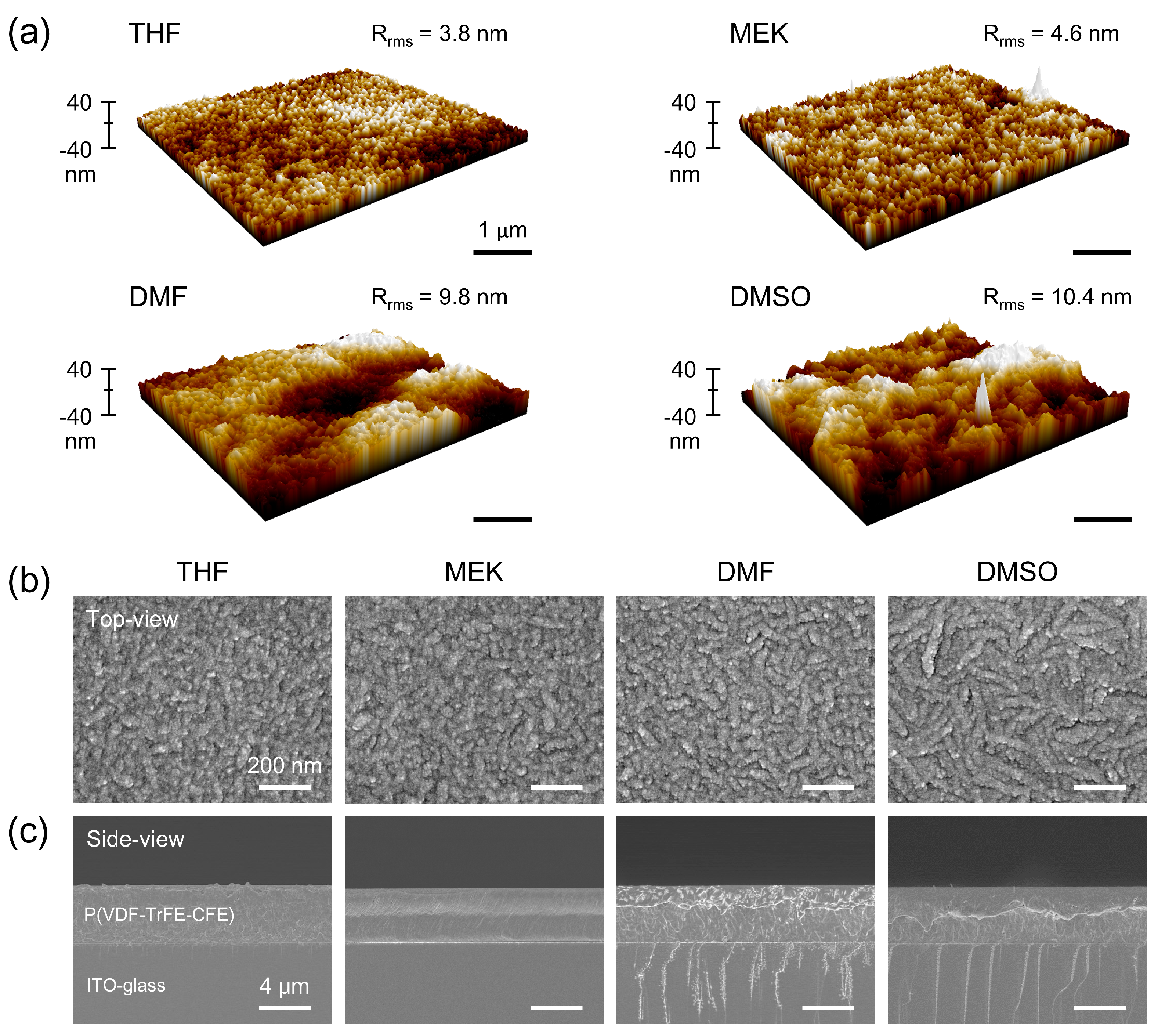
Figure 2a shows the atomic force microscopy images (5 × 5 μm2) of the terpolymer films. Regardless of the employed solvents, the surface morphology exhibits a similar pattern, displaying nano-sized hills and pits. However, the root-mean-square roughness (Rrms) increases with the increase in the dipole moment of solvent, as follows: 3.8, 4.6, 9.8 and 10.4 nm for THF, MEK, DMF and DMSO, respectively. Such solvent-dependent roughness is expected to affect the triboelectric output, as reported in the literature [30].
Figure 2b,c illustrate the top and side views of the scanning electron microscopy images, respectively. All P(VDF-TrFE-CFE) terpolymer films exhibit dense and uniform stacking on the ITO-glass substrate, with no discernable voids. Notably, all bar-coated films exhibit almost the same thickness of 4.4 μm, in sharp contrast to the spin-coated films (Figure S3).
From the top view of the images, it is evident that the P(VDF-TrFE-CFE) grains are long for high dipole moment solvents and short for low dipole moment solvents. Quantitative analysis of the images revealed that the length of grains was estimated to be 213 nm for the highest dipole moment of DMSO solvent and 120 nm for the lowest dipole moment of THF solvent. During the annealing, the molecular chains flow and self-organize to form rod-shaped grains [31]. The degree of overlap between swollen polymer chains is increased by high dipole moment solvents [32,33,34], which in turn leads to an increase in rod-shaped grains. In Table 1, we provide a summary of the microstructural properties of P(VDF-TrFE-CFE) terpolymer films obtained from different solvents.
Further investigation was conducted to ascertain the effect of solvent on the electrical properties of P(VDF-TrFE-CFE) terpolymer films. Figure S4a,b show the frequency-dependent dielectric constant and loss tanδ, respectively, of the terpolymers at room temperature. Given that the Curie temperature of P(VDF-TrFE-CFE) is close to the room temperature, the dielectric constant at 100 Hz (~55) and loss tanδ at 1 MHz (~0.55) are considerably larger than those of PVDF (dielectric constant of ~5, loss tanδ of 0.1) [35] and P(VDF-TrFE) (dielectric constant of ~10, loss tanδ of ~0.05) [36]. Although the difference is relatively minor, the dielectric constant of the terpolymer is greater for the high dipole moment of DMF and DMSO than for the low dipole moment of THF and MEK solvents.
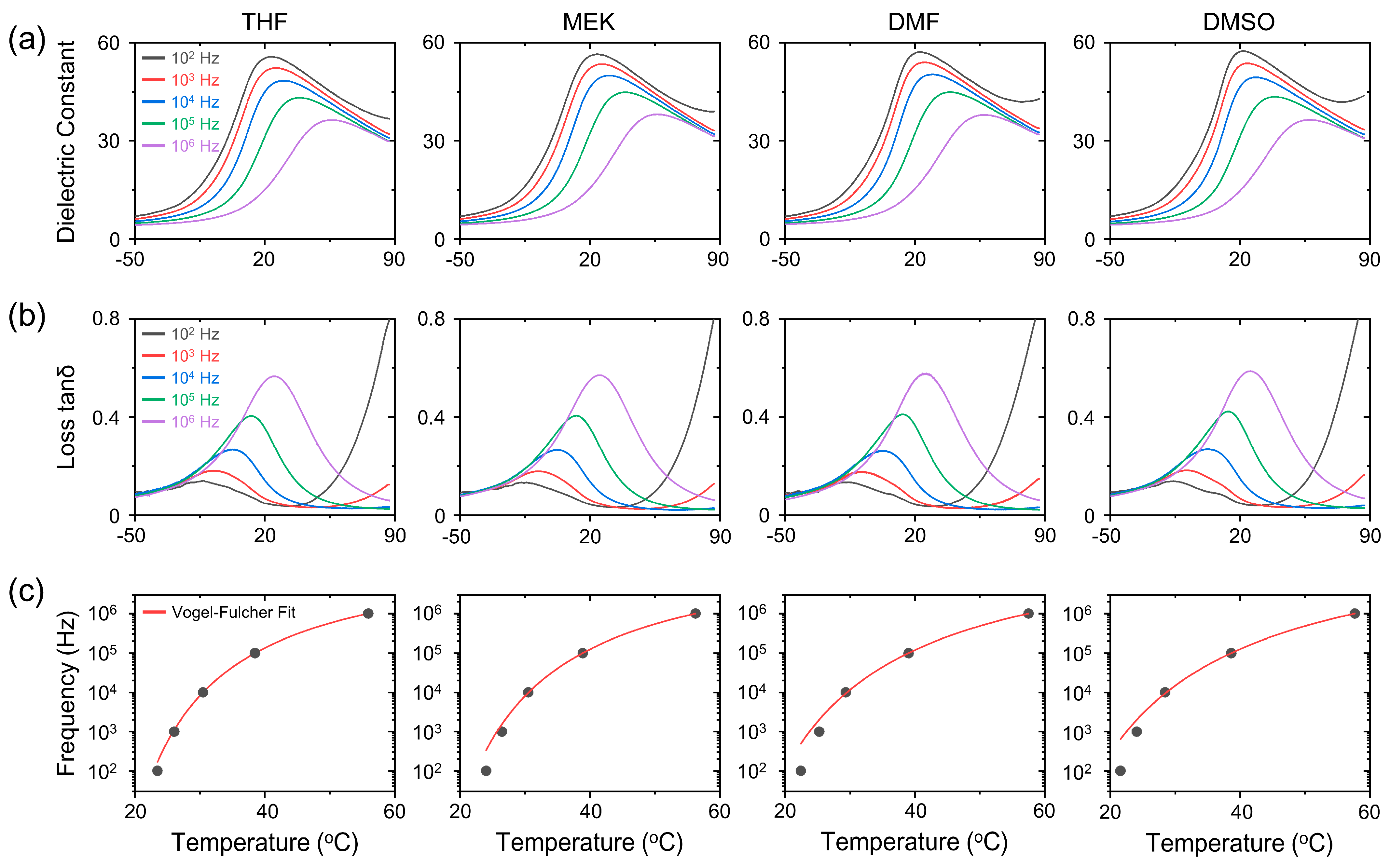
Figure 3a,b show the temperature-dependent dielectric constant and loss tanδ, respectively, of P(VDF-TrFE-CFE) terpolymer obtained from THF, MEK, DMF and DMSO solvents. Both the dielectric constant and loss tanδ exhibit strong frequency dispersion over a broad temperature range. The maximum dielectric constant and loss tanδ peaks shift to higher temperatures with increasing frequency.
Such relaxor behaviors can be modeled by Vogel–Fulcher’s law as follows:
f m = f 0 e x p ( U k B T m T f )
where U is the activation energy, k B is the Boltzmann constant, f m is the peak frequency, T m is the peak temperature, and T f is the freezing temperature [37,38]. As shown in Figure 3c, the Vogel–Fulcher’s law explains the relationship between f m and T m for all solvents well. The activation energy and freezing temperature of P(VDF-TrFE-CFE) terpolymer films obtained from various solvents are listed in Table 2. The relatively large activation energy and low freezing temperature in high dipole moment solvents, such as DMF and DMSO, are likely related to the larger mean volume of the polar region [39].
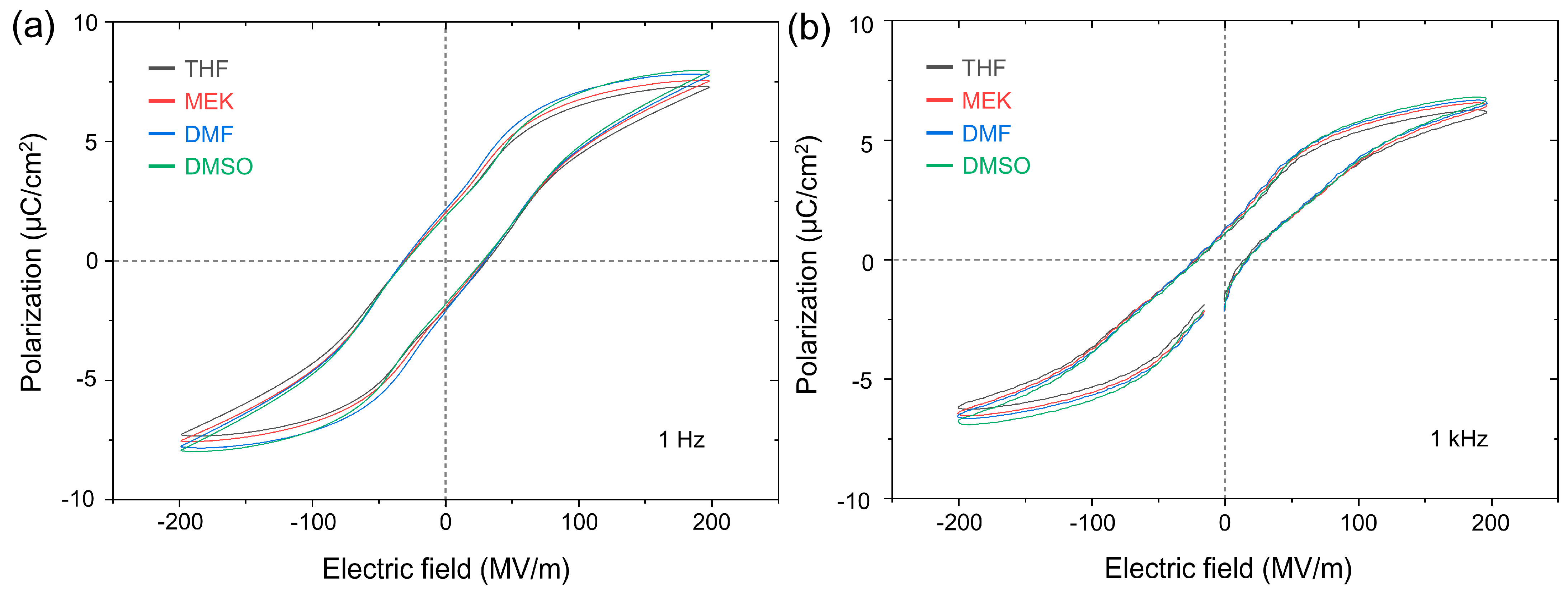
The relaxor behavior of P(VDF-TrFE-CFE) can be further confirmed from the frequency-dependent polarization–electric field (P-E) hysteresis loops. Figure 4a,b show the solvent-dependent P-E hysteresis loop of P(VDF-TrFE-CFE) terpolymer at 1 Hz and 1 kHz, respectively. Detailed P-E loops for each solvent at various frequencies are shown in Figure S5. Overall, the P-E loops at 1 Hz exhibit a double-hysteresis loop-like behavior, while the loops at 1 kHz exhibit an antiferroelectric-like behavior [40]. The polarization in the low field region decreases significantly, while that in the high field region decreases slightly with increasing frequency. The quantitative analysis revealed a 37% decrease in polarization at 0 MV/m decreased from 1.9 μC/cm2 at 1 Hz to 1.2 μC/cm2 at 1 kHz, while that at 200 MV/m decreased by 15% from 7.9 μC/cm2 at 1 Hz to 6.7 μC/cm2 at 1 kHz for DMSO. Such behavior can be explained by the fact that the dipole from CFE is relatively insensitive to applied frequency and responds at a high electric field, in contrast to the dipoles from VDF and TrFE [41]. A significant influence on polarization at high electric fields may indicate that the solvent effectively affects the CFE molecule. The solvent-dependent saturated polarization, remnant polarization and coercive field are listed in Table 3.
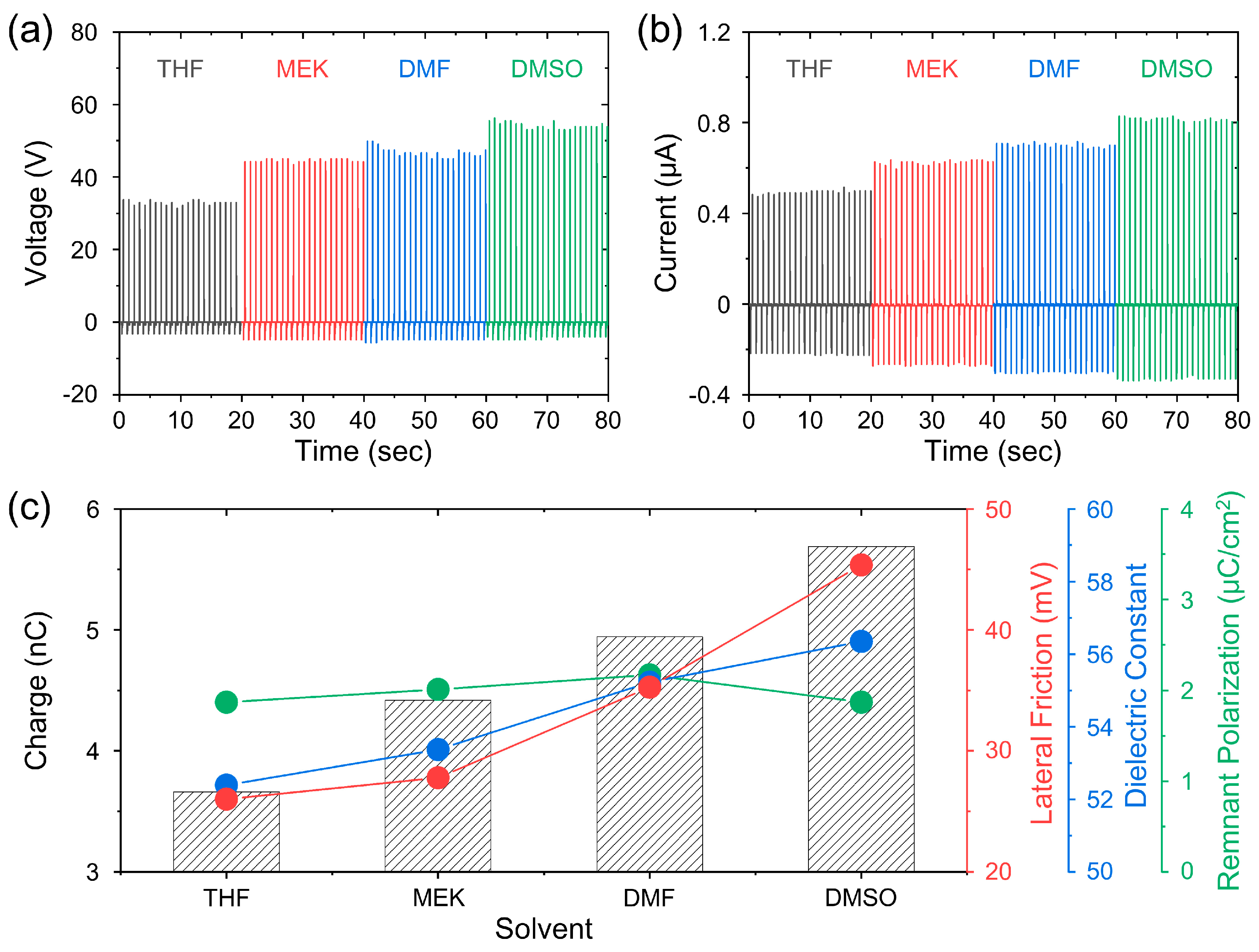
Following the characterization of the structural, mechanical, microstructural and electrical properties of P(VDF-TrFE-CFE) terpolymer films obtained from various solvents, we have investigated the effect of solvent on the triboelectric output performance of P(VDF-TrFE-CFE) films. In order to ensure the reliability of the results, all experimental parameters were kept constant, with the exception of the P(VDF-TrFE-CFE) films. Figure 5a,b show the solvent-dependent open-circuit voltage and short-circuit current of P(VDF-TrFE-CFE)-based triboelectric nanogenerators (TENGs), respectively. It is evident that the output performance of the TENG exhibits a clear increase with the increased dipole moment of the solvent. In Table 4, we provide a summary of the solvent-dependent peak-to-peak voltage and peak-to-peak current for each P(VDF-TrFE-CFE)-based TENG.
Figure 5c illustrates the solvent-dependent triboelectric charge along with the remnant polarization and dielectric constant of P(VDF-TrFE-CFE) terpolymers. It should be noted that the triboelectric charge was obtained by integrating the triboelectric current over time. As is evident, the almost constant remnant polarization and the slight increase in dielectric constant (~7%) are insufficient to account for the considerable enhancement in triboelectric charge (~55%) observed for P(VDF-TrFE-CFE) obtained from DMSO solvent compared to that from the THF solvent.
In order to gain insight into the principal mechanism underlying the solvent-dependent triboelectric output performance, we present the solvent-dependent root-mean-square value of lateral friction in Figure 5c [42]. In contrast to dielectric constant and remnant polarization, the lateral friction is markedly enhanced (~75%) in the film obtained from DMSO in comparison to that from THF. Given the positive correlation between lateral friction and surface roughness, as evidenced in Figure S6, it can be postulated that the solvent-dependent triboelectric output of P(VDF-TrFE-CFE)-based TENGs is related to the variation in friction, which may be attributed to grain growth-induced surface morphology.

4. Summary

In summary, we systematically investigated the effects of solvent on the crystallinity, Young’s modulus, surface morphology and electrical properties of bar-coated P(VDF-TrFE-CFE) terpolymer films on an ITO-glass substrate. In contrast to spin-coating, the bar-coating resulted in almost the same thickness (~4.4 μm) of film, regardless of the employed solvent. The terpolymer film obtained from DMSO solvent exhibited a long rod-shaped grain (length of 213.6 nm and width of 48.2 nm), while the film obtained from THF solvent displayed a short rod-shape (length of 119.8 nm and width of 39.7 nm). The morphology change is accompanied by a slight increase (~5%) in crystallinity and a significant increase (~270%) in roughness. Furthermore, temperature- and frequency-dependent dielectric constant and polarization measurements showed that relaxor ferroelectricity is preserved in P(VDF-TrFE-CFE) with almost the same remnant polarization for all solvents. The dielectric constant (~7%) and saturated polarization (~9%) were observed to increase slightly in DMF and DSMO solvents with a higher dipole moment. In the contact–separation between Al and P(VDF-TrFE-CFE), we observed a clear solvent-dependent triboelectric charge, i.e., 3.7, 4.4, 4.9 and 5.7 nC for THF, MEK, DMF and DMSO solvents, respectively. By comparing relevant physical parameters, it is concluded that surface morphology-induced lateral friction plays a dominant role in the solvent-dependent triboelectric output in P(VDF-TrFE-CFE).

Supplementary Materials

The following supporting information can be downloaded at: https://www.mdpi.com/article/10.3390/cryst14070664/s1, Figure S1: Schematic fabrication process of P(VDF-TrFE-CFE) films on an ITO-glass substrate, (i) pouring, (ii) bar-coating, (iii) drying and (iv) crystallization. Figure S2: (a) Schematic diagram and (b) digital image of a P(VDF-TrFE-CFE)-based triboelectric nanogenerator. Contact and separation occurred between the Al electrode and the P(VDF-TrFE-CFE) polymer. The top (Al) and bottom (ITO) electrodes are connected to an electrometer for triboelectric output measurement. Figure S3: Side view of spin-coated P(VDF-TrFE-CFE) films. In contrast to bar-coating, spin-coating results in different thicknesses of films obtained from THF (~2.2 μm), MEK (~2.2 μm), DMF (~1.1 μm) and DMSO (~1.5 μm). Figure S4: Frequency-dependent (a) dielectric constant and (b) loss tanδ of P(VDF-TrFE-CFE) films at room temperature. Figure S5: Frequency-dependent polarization–electric field (P-E) hysteresis loops of P(VDF-TrFE-CFE) obtained from (a) THF, (b) MEK, (c) DMF and (d) DMSO solvents. Figure S6: (a) Lateral friction microscopy images of P(VDF-TrFE-CFE) obtained from THF, MEK, DMF and DMSO solvents. The root-mean-square values of friction (Frms) are shown in each image. (b) Positive correlation between lateral friction and roughness.

Author Contributions

Conceptualization, J.H.J. and Y.C.H.; investigation and data curation, Y.C.H., H.S.A., J.H.L., K.H.K. and J.H.K.; writing—original draft preparation, J.H.J. and Y.C.H.; writing—review and editing, J.H.J., Y.C.H. and J.H.K. All authors have read and agreed to the published version of the manuscript.

Funding

This work was supported by Inha University Research Grant.

Data Availability Statement

Data are contained within the article or Supplementary Materials.

Conflicts of Interest

The authors declare no conflicts of interest.

References

  1. Fan, F.-R.; Tian, Z.-Q.; Wang, Z.L. Flexible triboelectric generator. Nano Energy 2012, 1, 328–334. [Google Scholar] [CrossRef]
  2. Wang, Z.L. Triboelectric nanogenerators as new energy technology for self-powered systems and as active mechanical and chemical sensors. ACS Nano 2013, 7, 9533–9557. [Google Scholar] [CrossRef] [PubMed]
  3. Kim, H.S.; Hur, S.; Lee, D.-G.; Shin, J.; Qiao, H.; Mun, S.; Lee, H.; Moon, W.; Kim, Y.; Baik, J.M. Ferroelectrically augmented contact electrification enables efficient acoustic energy transfer through liquid and solid media. Energy Environ. Sci. 2022, 15, 1243–1255. [Google Scholar] [CrossRef]
  4. Kim, D.W.; Lee, J.H.; Kim, J.K.; Jeong, U. Material aspects of triboelectric energy generation and sensors. NPG Asia Mater. 2020, 12, 6. [Google Scholar] [CrossRef]
  5. Zou, H.; Zhang, Y.; Guo, L.; Wang, P.; He, X.; Dai, G.; Zheng, H.; Chen, C.; Wang, A.C.; Xu, C. Quantifying the triboelectric series. Nat. Commun. 2019, 10, 1427. [Google Scholar] [CrossRef] [PubMed]
  6. Shin, S.-H.; Kwon, Y.H.; Kim, Y.-H.; Jung, J.-Y.; Lee, M.H.; Nah, J. Triboelectric charging sequence induced by surface functionalization as a method to fabricate high performance triboelectric generators. ACS Nano 2015, 9, 4621–4627. [Google Scholar] [CrossRef] [PubMed]
  7. Wang, S.; Zi, Y.; Zhou, Y.S.; Li, S.; Fan, F.; Lin, L.; Wang, Z.L. Molecular surface functionalization to enhance the power output of triboelectric nanogenerators. J. Mater. Chem. A 2016, 4, 3728–3734. [Google Scholar] [CrossRef]
  8. Yun, S.-Y.; Kim, M.H.; Yang, G.G.; Choi, H.J.; Kim, D.-W.; Choi, Y.-K.; Kim, S.O. A triboelectric nanogenerator with synergistic complementary nanopatterns fabricated by block copolymer self-assembly. J. Mater. Chem. A 2024, 12, 11302–11309. [Google Scholar] [CrossRef]
  9. Zhu, G.; Lin, Z.-H.; Jing, Q.; Bai, P.; Pan, C.; Yang, Y.; Zhou, Y.; Wang, Z.L. Toward large-scale energy harvesting by a nanoparticle-enhanced triboelectric nanogenerator. Nano Lett. 2013, 13, 847–853. [Google Scholar] [CrossRef]
  10. Kim, J.-K.; Han, G.H.; Kim, S.-W.; Kim, H.J.; Purbia, R.; Lee, D.-M.; Kim, J.K.; Hwang, H.J.; Song, H.-C.; Choi, D. Electric-field-driven interfacial trapping of drifting triboelectric charges via contact electrification. Energy Environ. Sci. 2023, 16, 598–609. [Google Scholar] [CrossRef]
  11. Chung, J.; Lee, S.; Yong, H.; Moon, H.; Choi, D.; Lee, S. Self-packaging elastic bellows-type triboelectric nanogenerator. Nano Energy 2016, 20, 84–93. [Google Scholar] [CrossRef]
  12. Lee, D.W.; Jeong, D.G.; Kim, J.H.; Kim, H.S.; Murillo, G.; Lee, G.-H.; Song, H.-C.; Jung, J.H. Polarization-controlled PVDF-based hybrid nanogenerator for an effective vibrational energy harvesting from human foot. Nano Energy 2020, 76, 105066. [Google Scholar] [CrossRef]
  13. Rana, S.S.; Rahman, M.T.; Salauddin, M.; Sharma, S.; Maharjan, P.; Bhatta, T.; Cho, H.; Park, C.; Park, J.Y. Electrospun PVDF-TrFE/MXene nanofiber mat-based triboelectric nanogenerator for smart home appliances. ACS Appl. Mater. Interfaces 2021, 13, 4955–4967. [Google Scholar] [CrossRef]
  14. Bai, P.; Zhu, G.; Zhou, Y.S.; Wang, S.; Ma, J.; Zhang, G.; Wang, Z.L. Dipole-moment-induced effect on contact electrification for triboelectric nanogenerators. Nano Res. 2014, 7, 990–997. [Google Scholar] [CrossRef]
  15. Seung, W.; Yoon, H.J.; Kim, T.Y.; Ryu, H.; Kim, J.; Lee, J.H.; Lee, J.H.; Kim, S.; Park, Y.K.; Park, Y.J. Boosting power-generating performance of triboelectric nanogenerators via artificial control of ferroelectric polarization and dielectric properties. Adv. Energy Mater. 2017, 7, 1600988. [Google Scholar] [CrossRef]
  16. Jeong, D.G.; Ko, Y.J.; Kim, J.H.; Kong, D.S.; Hu, Y.C.; Lee, D.W.; Im, S.H.; Lee, J.; Kim, M.S.; Lee, G.-H. On the origin of enhanced power output in ferroelectric polymer-based triboelectric nanogenerators: Role of dipole charge versus piezoelectric charge. Nano Energy 2022, 103, 107806. [Google Scholar] [CrossRef]
  17. Šutka, A.; Mālnieks, K.; Linarts, A.; Timusk, M.; Jurķāns, V.; Gorņevs, I.; Blūms, J.; Bērziņa, A.; Joost, U.; Knite, M. Inversely polarised ferroelectric polymer contact electrodes for triboelectric-like generators from identical materials. Energy Environ. Sci. 2018, 11, 1437–1443. [Google Scholar] [CrossRef]
  18. Ong, D.T.K.; Koay, J.S.C.; Sim, M.T.; Aw, K.C.; Nakajima, T.; Chen, B.; Tan, S.T.; Gan, W.C. High performance composition-tailored PVDF triboelectric nanogenerator enabled by low temperature-induced phase transition. Nano Energy 2023, 113, 108555. [Google Scholar] [CrossRef]
  19. Shvartsman, V.V.; Lupascu, D.C. Lead-free relaxor ferroelectrics. J. Am. Ceram. Soc. 2012, 95, 1–26. [Google Scholar] [CrossRef]
  20. Kim, J.; Lee, J.H.; Ryu, H.; Lee, J.H.; Khan, U.; Kim, H.; Kwak, S.S.; Kim, S.W. High-performance piezoelectric, pyroelectric, and triboelectric nanogenerators based on P (VDF-TrFE) with controlled crystallinity and dipole alignment. Adv. Funct. Mater. 2017, 27, 1700702. [Google Scholar] [CrossRef]
  21. Available online: https://piezotech.arkema.com/en/Products/high-k-terpolymers/ (accessed on 16 July 2024).
  22. Patterson, A. The Scherrer formula for X-ray particle size determination. Phys. Rev. 1939, 56, 978. [Google Scholar] [CrossRef]
  23. Bao, H.-M.; Song, J.-F.; Zhang, J.; Shen, Q.-D.; Yang, C.-Z.; Zhang, Q. Phase transitions and ferroelectric relaxor behavior in P (VDF− TrFE− CFE) terpolymers. Macromolecules 2007, 40, 2371–2379. [Google Scholar] [CrossRef]
  24. Ma, W.; Zhang, J.; Wang, X.; Wang, S. Effect of PMMA on crystallization behavior and hydrophilicity of poly (vinylidene fluoride)/poly (methyl methacrylate) blend prepared in semi-dilute solutions. Appl. Surf. Sci. 2007, 253, 8377–8388. [Google Scholar] [CrossRef]
  25. Della Schiava, N.; Pedroli, F.; Thetpraphi, K.; Flocchini, A.; Le, M.-Q.; Lermusiaux, P.; Capsal, J.-F.; Cottinet, P.-J. Effect of beta-based sterilization on P (VDF-TrFE-CFE) terpolymer for medical applications. Sci. Rep. 2020, 10, 8805. [Google Scholar] [CrossRef] [PubMed]
  26. Klein, R.J.; Runt, J.; Zhang, Q. Influence of Crystallization Conditions on the Microstructure and Electromechanical Properties of Poly (vinylidene fluoride− trifluoroethylene− chlorofluoroethylene) Terpolymers. Macromolecules 2003, 36, 7220–7226. [Google Scholar] [CrossRef]
  27. Tung, K.-L.; Lu, K.-T.; Ruaan, R.-C.; Lai, J.-Y. Molecular dynamics study of the effect of solvent types on the dynamic properties of polymer chains in solution. Desalination 2006, 192, 380–390. [Google Scholar] [CrossRef]
  28. Šutka, A.; Mālnieks, K.; Lapčinskis, L.; Kaufelde, P.; Linarts, A.; Bērziņa, A.; Zābels, R.; Jurķāns, V.; Gorņevs, I.; Blūms, J. The role of intermolecular forces in contact electrification on polymer surfaces and triboelectric nanogenerators. Energy Environ. Sci. 2019, 12, 2417–2421. [Google Scholar] [CrossRef]
  29. Sperling, L.H. Introduction to Physical Polymer Science; John Wiley & Sons: Hoboken, NJ, USA, 2005. [Google Scholar]
  30. Seol, M.L.; Woo, J.H.; Lee, D.I.; Im, H.; Hur, J.; Choi, Y.K. Nature-replicated nano-in-micro structures for triboelectric energy harvesting. Small 2014, 10, 3887–3894. [Google Scholar] [CrossRef] [PubMed]
  31. Kimura, K.; Kobayashi, K.; Yamada, H.; Horiuchi, T.; Ishida, K.; Matsushige, K. Study on orientation mechanisms of poly (vinylidenefluoride-trifluoroethylene) molecules aligned by atomic force microscopy. Appl. Surf. Sci. 2006, 252, 5489–5494. [Google Scholar] [CrossRef]
  32. Monroy, F.; Arriaga, L.; Langevin, D. Langmuir polymer films: Recent results and new perspectives. Phys. Chem. Chem. Phys. 2012, 14, 14450–14459. [Google Scholar] [CrossRef]
  33. Kunwar, D.; Vazquez, I.R.; Jackson, N. Effects of solvents on synthesis of piezoelectric polyvinylidene fluoride trifluoroethylene thin films. Thin Solid Films 2022, 757, 139414. [Google Scholar] [CrossRef]
  34. Hansen, C.M. Hansen Solubility Parameters: A User’s Handbook, 2nd ed.; CRC Press: Boca Raton, FL, USA, 2007. [Google Scholar]
  35. Luo, B.; Wang, X.; Wang, Y.; Li, L. Fabrication, characterization, properties and theoretical analysis of ceramic/PVDF composite flexible films with high dielectric constant and low dielectric loss. J. Mater. Chem. A 2014, 2, 510–519. [Google Scholar] [CrossRef]
  36. Wang, J.-W.; Shen, Q.-D.; Yang, C.-Z.; Zhang, Q.-M. High dielectric constant composite of P (VDF− TrFE) with grafted copper phthalocyanine oligomer. Macromolecules 2004, 37, 2294–2298. [Google Scholar] [CrossRef]
  37. Pirc, R.; Blinc, R. Vogel-Fulcher freezing in relaxor ferroelectrics. Phys. Rev. B 2007, 76, 020101. [Google Scholar] [CrossRef]
  38. Viehland, D.; Jang, S.; Cross, L.E.; Wuttig, M. Freezing of the polarization fluctuations in lead magnesium niobate relaxors. J. Appl. Phys. 1990, 68, 2916–2921. [Google Scholar] [CrossRef]
  39. Cross, L. Relaxor ferroelectrics. In Piezoelectricity; Heywang, W., Lubits, K., Wersing, W., Eds.; Springer: Berlin/Heidelberg, Germany, 2008; Volume 114, pp. 131–155. [Google Scholar]
  40. Hambal, Y.; Shvartsman, V.V.; Lewin, D.; Huat, C.H.; Chen, X.; Michiels, I.; Zhang, Q.; Lupascu, D.C. Effect of composition on polarization hysteresis and energy storage ability of P (VDF-TrFE-CFE) relaxor terpolymers. Polymers 2021, 13, 1343. [Google Scholar] [CrossRef]
  41. Tsutsumi, N.; Okumachi, K.; Kinashi, K.; Sakai, W. Re-evaluation of the origin of relaxor ferroelectricity in vinylidene fluoride terpolymers: An approach using switching current measurements. Sci. Rep. 2017, 7, 15871. [Google Scholar] [CrossRef]
  42. Lee, J.-Y.; Kim, J.H.; Jung, Y.; Shin, J.C.; Lee, Y.; Kim, K.; Kim, N.; van der Zande, A.M.; Son, J.; Lee, G.-H. Evolution of defect formation during atomically precise desulfurization of monolayer MoS2. Commun. Mater. 2021, 2, 80. [Google Scholar] [CrossRef]
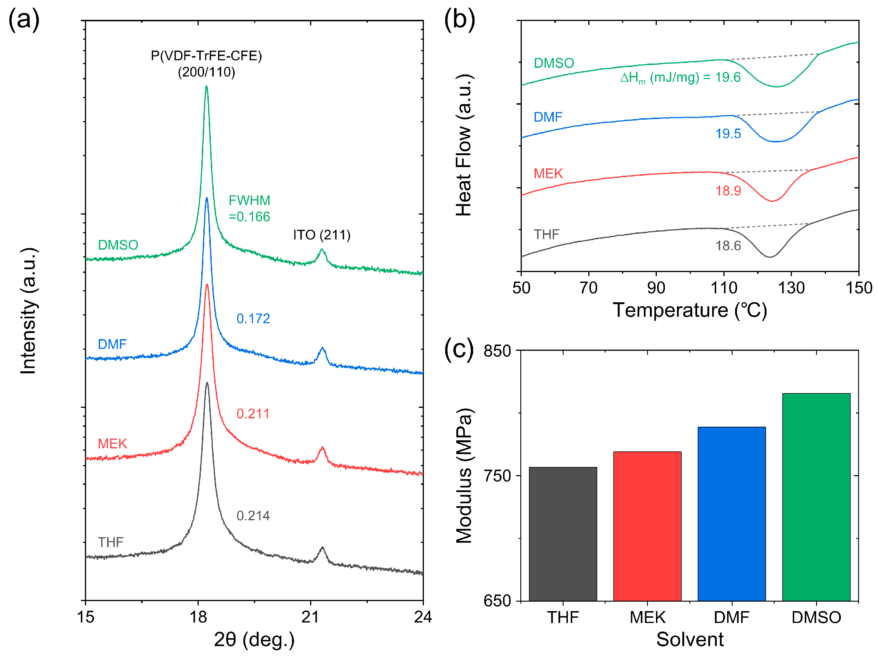
Figure 1. (a) X-ray diffraction pattern; (b) differential scanning calorimetry heating thermogram; (c) Young’s modulus of P(VDF-TrFE-CFE) terpolymer films obtained from THF, MEK, DMF and DMSO solvents. The dashed lines near the melting temperature in (b) represent the linear baselines for the enthalpy calculation.
Crystals 14 00664 g001
Figure 2. (a) Atomic force microscopy (5 × 5 μm2); (b) top and (c) side views of scanning electron microscopy images of P(VDF-TrFE-CFE) terpolymer films on an ITO-glass substrate. In (a), we show the root-mean-square values of roughness (Rrms) for each image.
Crystals 14 00664 g002
Figure 3. Temperature-dependent (a) dielectric constant and (b) loss tanδ of P(VDF-TrFE-CFE) terpolymer films obtained from THF, MEK, DMF and DMSO solvents. (c) Vogel–Fulcher law fitting (red lines) of dielectric constant peaks with respect to temperature and frequency.
Crystals 14 00664 g003
Figure 4. Polarization–electric field (P-E) hysteresis loops of P(VDF-TrFE-CFE) terpolymer films obtained from THF, MEK, DMF and DMSO solvents at driving frequencies of (a) 1 Hz and (b) 1 kHz.
Crystals 14 00664 g004
Figure 5. (a) Open-circuit voltage and (b) short-circuit current of P(VDF-TrFE-CFE)-based triboelectric nanogenerators (TENGs). (c) Comparison of the triboelectric charge with respect to lateral friction, dielectric constant and remnant polarization of P(VDF-TrFE-CFE) terpolymer films obtained from THF, MEK, DMF and DMSO solvents.
Crystals 14 00664 g005
Table 1. Solvent-dependent crystallinity, grain length, grain width, thickness and roughness of P(VDF-TrFE-CFE) terpolymer films.
SolventCrystallinity (%)Grain Length (nm)Grain Width (nm)Thickness (μm)Roughness (nm)
THF44.4119.839.74.43.8
MEK45.1155.340.14.24.6
DMF46.4164.543.54.49.8
DSMO46.7213.648.24.410.4
Table 2. Activation energy and freezing temperature of relaxor ferroelectric P(VDF-TrFE-CFE) terpolymers obtained from various solvents.
SolventActivation Energy (meV)Freezing Temperature (°C)
THF15.98.8
MEK17.96.9
DMF24.00
DMSO26.7−3.4
Table 3. Frequency-dependent saturated and remnant polarizations and coercive field of P(VDF-TrFE-CFE) terpolymer films.
SolventSaturated Polarization (μC/cm2)Remnant Polarization (μC/cm2)Coercive Field (MV/m)
1 Hz1 kHz1 Hz1 kHz1 Hz1 kHz
THF7.36.21.91.130.221.1
MEK7.66.52.01.330.922.5
DMF7.86.62.21.331.923.8
DMSO8.06.81.91.130.020.2
Table 4. Peak-to-peak voltage and peak-to-peak current of P(VDF-TrFE-CFE)-based triboelectric nanogenerators.
SolventPeak-to-Peak Voltage (V)Peak-to-Peak Current (μA)
THF35.60.7
MEK49.80.8
DMF51.81.0
DSMO58.61.1
Disclaimer/Publisher’s Note: The statements, opinions and data contained in all publications are solely those of the individual author(s) and contributor(s) and not of MDPI and/or the editor(s). MDPI and/or the editor(s) disclaim responsibility for any injury to people or property resulting from any ideas, methods, instructions or products referred to in the content.