Abstract
It is of great significance in the field of engineering to repair the surface defects of ZM6 cast magnesium alloy by an arc welding method. Compared with the traditional tungsten inert gas (TIG) welding repair technology, cold metal transfer (CMT) welding repair has the advantages of low heat input, small repair deformation, and high efficiency. It is of great research value to repair the surface defects of ZM6 cast magnesium alloy by CMT welding. In this paper, the effect of CMT welding repair parameters on defect repair forming is systematically studied, and a repair process window free of unfused defects is obtained. The effects of preheating temperature of base material, wire-feeding speed, welding speed, stick-out length of welding wire and shielding gas flow on the spread of magnesium alloy melt and weld formation were investigated by a surface surfacing method. During the welding process, a camera was used to capture images of the arc and droplet features. A pit defect with a depth of 11.5 mm was machined on the surface of the casting, and the effect of five different repair paths on the formation of the repair area was studied. In order to make the repair area have better fusion, reasonable repair parameters are as follows: The preheating temperature range is 310–450 °C, the wire-feeding speed range is 5–7 m/min, the welding speed range is 8–10 mm/s, the stick-out length of the welding wire is 12 mm, the shielding gas flow rate is 20 L/min, and the repair path adopts a continuous linear reciprocating welding path. This study has important significance for guiding the development of CMT repair technology of cast magnesium alloy.
1. Introduction
Magnesium alloy, as a lightweight material, has extensive applications in fields such as aviation, aerospace, and the automotive industry due to its excellent casting properties and high specific strength [1]. During the casting process of magnesium alloys, defects such as pores and cracks often occur, affecting the use of the castings. To address these surface defects on the castings, welding repair methods can be used to restore their functional performance, thereby avoiding the high costs associated with re-casting. The welding method is used to repair the surface defects of cast magnesium alloy, which has good economic and social benefits.
At present, the welding repair of cast magnesium alloy defects at home and abroad mainly include arc welding repair, laser welding repair, and friction stir welding repair [2]. Compared with laser welding repair and friction stir welding repair, arc welding repair has broad development prospects due to its low cost and flexible repair path. The arc welding repair methods for casting magnesium alloy defects mainly include TIG welding and CMT welding. Yang et al. studied the effect of helium–argon shielding gas composition on the repair of hole-like defects and linear defects in castings for the repair process of TIG welding without filling wire. The test material was AZ91D magnesium alloy casting, the welding current was 160 A, and the welding speed was 4 mm/s. The study showed that when the helium content increased from 0 to 100%, the depth of the weld increased from 2.3 mm to 6.1 mm, and the depth–width ratio increased from 0.23 to 0.47. When helium is used as a protective gas, the maximum defect depth that can be repaired by TIG without filler is about 5 mm [3]. Song, Zhang, and Kang et al. used the activating flux tungsten inert gas (A-TIG) welding method to repair casting magnesium alloy defects in order to increase the repair depth and efficiency. The results showed that the defect depth that can be completely healed by A-TIG welding is significantly larger than that of TIG welding. In addition, after A-TIG welding, there are no porosity defects on the surface of the weld [4,5,6]. Zhang et al. studied the characteristics of argon arc welding repair of a ZM6 cast magnesium alloy. For grooves with a diameter of 10–40 mm, the following welding repair process (preheating before welding at 200 °C for 1 h; the welding current is 160 A; the shielding gas flow rate is 15 L/min) can be used to obtain repair welding joints without cracks, pores, and incomplete fusion defects. For defects with a diameter of 40 mm on the upper surface and a depth of 20 mm, 25 layers of fill are required to complete the repair. The hardness of the weld zone is the highest, followed by the hardness of the base material zone, which is higher than the hardness of the heat-affected zone [7]. Wang et al. used the TIG welding wire-filling method to repair the defects of ZM6 cast magnesium alloy. The repair welding parameters were as follows: an alternating current welding mode, current of 180 A, an arc length of 2~3 mm, an argon flow rate of 10 L/min, a welding wire diameter of 5.5 mm, a preheating temperature of 230 °C before welding, and two repair layers. After repair, the quality of the repair area was good and no cracking occurred. The tensile strength of the welded joint can reach 150 MPa, reaching 93.75 percent of the strength of the base material [8].
Yang et al. comprehensively elaborated the related issues of TIG filler wire welding repair technology for defects in magnesium alloy castings. It is believed that the temperature of the repair zone should be monitored during the repair process, and when the temperature is too high, the welding repair should be stopped to prevent the magnesium alloy from overheating [9]. Shalomeev et al. developed a scandium-containing filling material for the welding of Mg-Zr-Nd alloys for aircraft engine body castings. The developed filling material can be used to repair surface defects of aircraft engine bodies. After repair, the plasticity can be increased by 70% and the heat resistance can be increased by 1.8 times [10]. Assar et al. studied the effect of heat input on the microstructure and properties of TIG welding repair cast AZ91 magnesium alloy and showed that the size of the α-Mg phase in the weld metal increased, the thickness of the partial melting zone increased, and the tensile strength of the welded joint decreased [11]. Kocurek and others used the TIG welding method to repair QE22 cast magnesium alloy, studied the effect of different line energy, and concluded that QE22 alloy struggles to produce hot cracks when the online energy is less than 3.0 kJ/cm [12]. Adamiec et al. studied the repair of WE43 cast magnesium alloy with a thickness of 5 mm and believed that the main factors affecting the repair quality include the welding method, arc energy, and joint form. The author thinks that the best welding method for repair of cast magnesium alloy is tungsten argon arc welding, and the best range of arc energy is 3.0–3.5 kJ/cm [13]. Bendis uses TIG welding to repair the surface of cast magnesium–aluminum alloy. Before being repaired, the whole casting is preheated. The preheating temperature is 350–380 °C, the welding current is 110–150 A, the diameter of tungsten electrode is 3–4 mm, and the diameter of the welding wire is 5–6 mm. The fatigue performance of the repaired magnesium alloy meets the service requirements [14]. Adamiec et al. proposed a reasonable TIG repair method for the repair of AZ91D magnesium alloy castings. It is believed that alternating current welding should be selected for repair, the welding current should be as small as possible, and the cast magnesium alloy should be solid solution heat treatment. It is better to perform the welding repair process after the solution heat treatment, otherwise defects such as cracks are prone to occur [15].
For the arc repair technology of magnesium alloy, domestic and foreign research shows that most of the repair method of magnesium alloy castings is the traditional TIG welding, which is widely used in the actual production of magnesium alloy casting repair by virtue of its high economy and operability. However, TIG welding has a shallow depth of penetration, and when the defect that needs to be repaired is deep, the number of layers and channels that need to be repaired by welding is usually large, which reduces the production efficiency. Compared with TIG welding, CMT welding has the advantages of low heat input, stable metal transfer, and high welding efficiency [16]. The lower heat input of CMT process can help to suppress the problems that may occur in the process of welding magnesium alloy, such as droplet spatter, grain coarsening, thermal cracking, and thermal stress. However, there are few studies on the repair of cast magnesium alloy by the CMT welding method. More scholars pay attention to researching magnesium alloy CMT welding technology. For example, Shen et al. mainly studied the stability of AZ91 magnesium alloy during the CMT welding deposition, analyzed the influence of current waveform parameters on droplet transfer and arc behavior during magnesium alloy cladding, and optimized the current waveform parameters [17]. The research results of magnesium alloy CMT welding also have important guiding significance for the CMT welding repair technology of cast magnesium alloy defects.
ZM6 magnesium alloy is a rare earth magnesium alloy, with rare earth Nd being the main strengthening element of magnesium alloy, with good high-temperature mechanical properties and creep resistance. ZM6 magnesium alloy is widely used in the manufacture of aero-engine casing. In this paper, the forming law of CMT repair for ZM6 surface defects is systematically studied. When the defects of cast magnesium alloy are repaired by CMT welding, the premise of ensuring the quality of repair is that there is no incomplete fusion defect in the repair area. The fusion depth of the cast magnesium alloy repair substrate under the action of arc and the spreading of the magnesium alloy melt on the surface of the repair substrate directly determine the formation of the repair area. To this end, this study systematically studied the wire feed speed, welding speed, and preheating temperature on the formation of weld pool and the spreading behavior of magnesium alloy melt, analyzed the effect of wire stick-out length and protective gas flow on welding stability, clarified the best repair path, and obtained the repair process window to ensure good formation of the repair area. In this study, it is found that the preheating temperature of the substrate and wire-feeding speed have a great influence on the formation of the repair area, and the repair parameters with better repair forming are obtained by an orthogonal experiment. The optimal repair path in the CMT arc repair process is clarified. This study can provide theoretical guidance for the development of CMT welding repair technology of ZM6 cast magnesium alloy and has important engineering guidance value.
2. Materials and Methods
2.1. Materials
The base material to be repaired is ZM6 cast magnesium alloy, and the diameter of the welding wire used for repair is 1.2 mm. The material of the welding wire is the same as the material of the base material to be repaired, and it is also ZM6 welding wire. The composition of the welding wire is shown in Table 1.

Table 1.
Chemical composition of ZM6 welding wire.
2.2. Experimental Methods
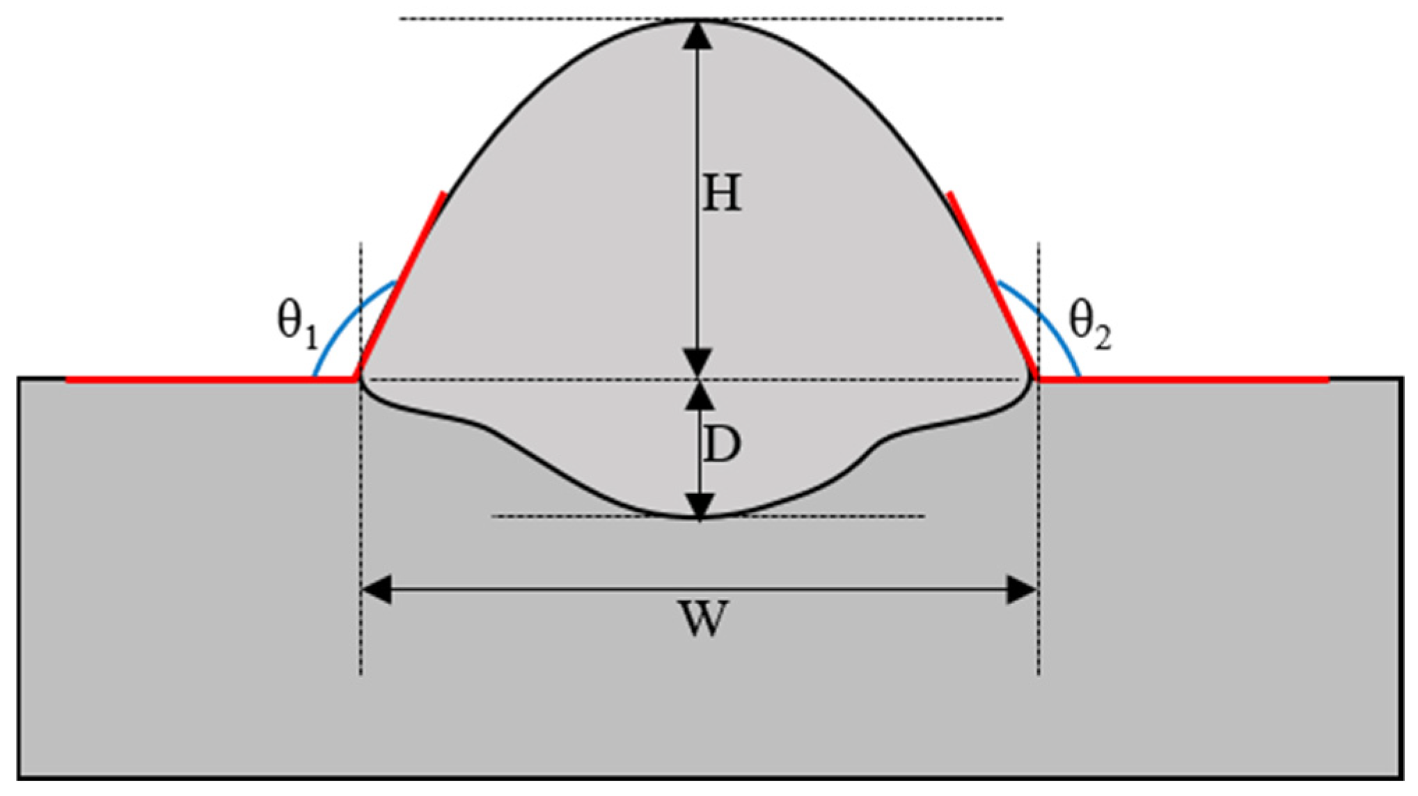
CMT welding selects a unified welding mode and automatically matches the wire-feeding speed, welding current, and welding voltage. In the process of CMT welding, the preheat temperature of the base material, the wire-feeding speed, and the welding speed have a comprehensive effect on the spread ability of the ZM6 cast magnesium alloy melt and the formation of the weld pool. In order to explore the effects of preheating temperature, wire-feeding speed, and welding speed on the spread and forming, the experiment was carried out by means of welding on the surface of ZM6 cast magnesium alloy, and an orthogonal test of 3 factors and 4 levels was designed, and the factor-level design table is shown in Table 2. Preheating was carried out by continuously heating the bottom of the base material. The preheating temperature range was 240–450 °C and the preheating time was 1.5 h. The wire-feeding speed range was 4–7 m/min. The welding speed range was 4–10 mm/s. Sixteen sets of orthogonal tests were carried out. During the experiment, the stick-out length of the welding wire was 12 mm and the shielding gas flow rate was 20 L/min. We selected the CMT welding characteristic curve of magnesium alloy. The arc was photographed by an XRIS camera during the welding process, and the arc shape and droplet characteristics under different welding parameters were compared. After welding, the surface and cross-sectional shape of the weld were observed, and Image Pro Plus software (version 6.0.0.260)was used to measure the contact angle (θ), width (W), depth (D), and height (H) of the surfacing layer. The measurement location schematic is shown in Figure 1, where the contact angle θ is the average of contact angles θ1 and θ2 in Figure 1. The forming data at different levels for different factors were summed and averaged for analysis.
Table 2.
Factor level design of orthogonal test.
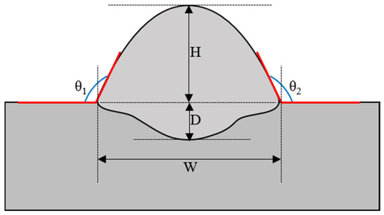
Figure 1.
Schematic diagram of measurement position for surfacing layer forming.
The effects of the stick-out length of welding wire and shielding gas flow on arc stability and weld surface protection were investigated. During the test, the preheating temperature was 450 °C, the preheating time was 1.5 h, the wire-feeding speed was 6 m/min, and the welding speed was 8 mm/s. The stick-out length of welding wire and shielding gas flow parameters were as follows: fixed shielding gas flow (30 L/min) and changing stick-out length of welding wire (8 mm, 12 mm, 16 mm); fixed stick-out length of welding wire (12 mm) and changing shielding gas flow (10 L/min, 20 L/min, 30 L/min). The stability of the arc was observed during welding. After the welding was completed, the surface gloss and formation of the weld were observed and analyzed.
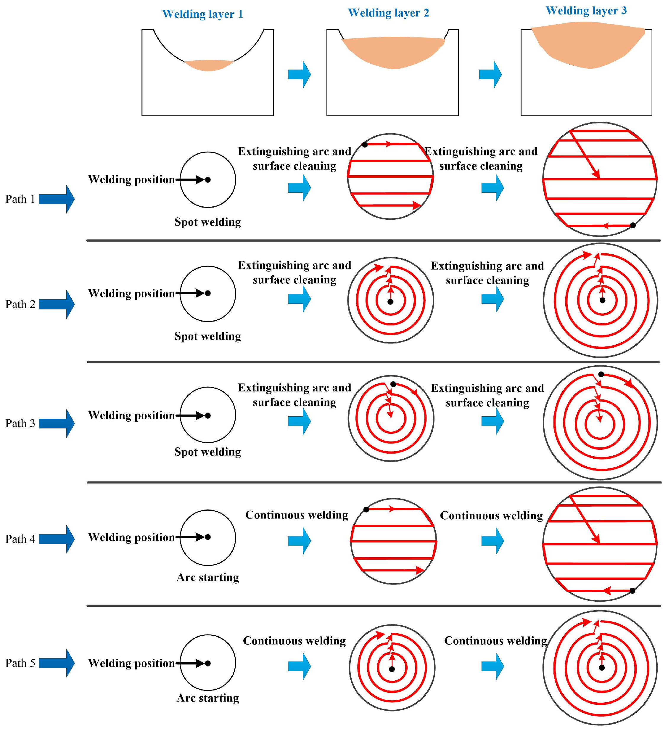
Aiming at the surface defects of ZM6 cast magnesium alloy, the actual CMT repair experiment was carried out to study the effect of the repair path on the repair forming. A schematic diagram of surface defect geometry of ZM6 cast magnesium alloy is shown in Figure 2. The defect geometry was a 1/4 spherical cap, the diameter of the upper surface of the defect was 40 mm, and the maximum depth of the defect was 11.5 mm. The effects of five different repair paths on the fusion of the repair area were explored, and a schematic diagram of the repair path is shown in Figure 3. The red arrow represents the arc trajectory. The black dots represent the arc starting position. During the experiment, the preheating temperature was 450 °C, the preheating time was 1.5 h, the wire-feeding speed was 7 m/min, and the welding speed was 8 mm/s. After repair, the section of the repair area (AO, BO, CO, and DO) was cut with wire cutters, and the section was polished and corroded. The internal fusion condition was observed by an optical microscope.
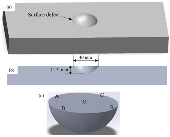
Figure 2.
Schematic diagram of 1/4 spherical cap defect size: (a) three-dimensional graph; (b) two-dimensional section; (c) section position.
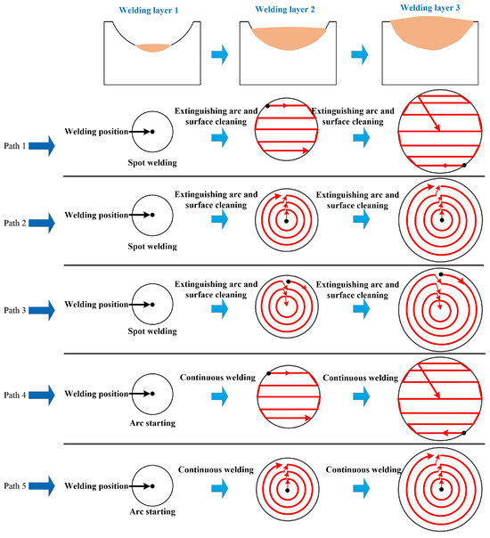
Figure 3.
Schematic diagram of five different repair paths (from path 1 to path 5).
3. Results
3.1. Melt Spreading and Surfacing Forming Analysis of Magnesium Alloy under Different Repair Parameters
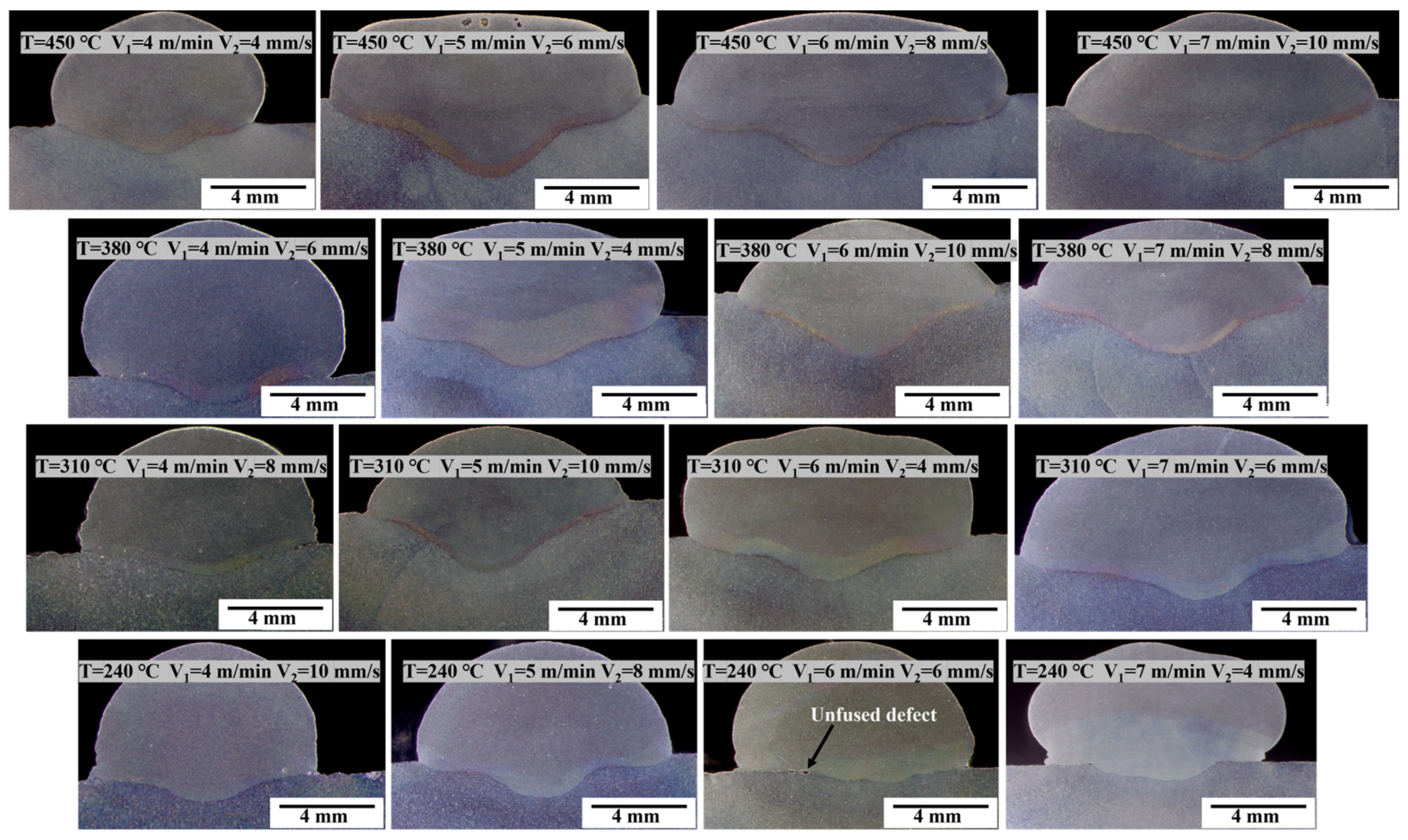
The effects of wire-feeding speed, welding speed, and preheating temperature on the spread of ZM6 cast magnesium alloy melt and surfacing forming were explored in 16 sets of orthogonal experiments. The cross-sectional morphology of the surfacing layer obtained with different repair parameters is shown in Figure 4, from which it can be seen that the preheating temperature has a direct effect on the penetration of the surfacing layer, and with the increase in the preheating temperature, the penetration of the surfacing layer increases as a whole. When the preheating temperature is 240 °C, the penetration is shallow. When the preheating temperature is 240 °C, the wire-feeding speed is 6 m/min and the welding speed is 6 mm/s, and there is an incomplete fusion phenomenon.
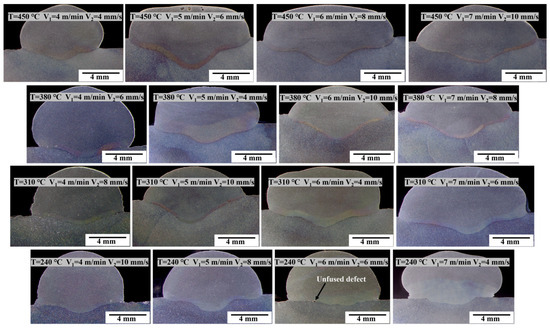
Figure 4.
Cross-sectional morphology of the welding layer with different preheating temperature, wire-feeding speed and welding speed.
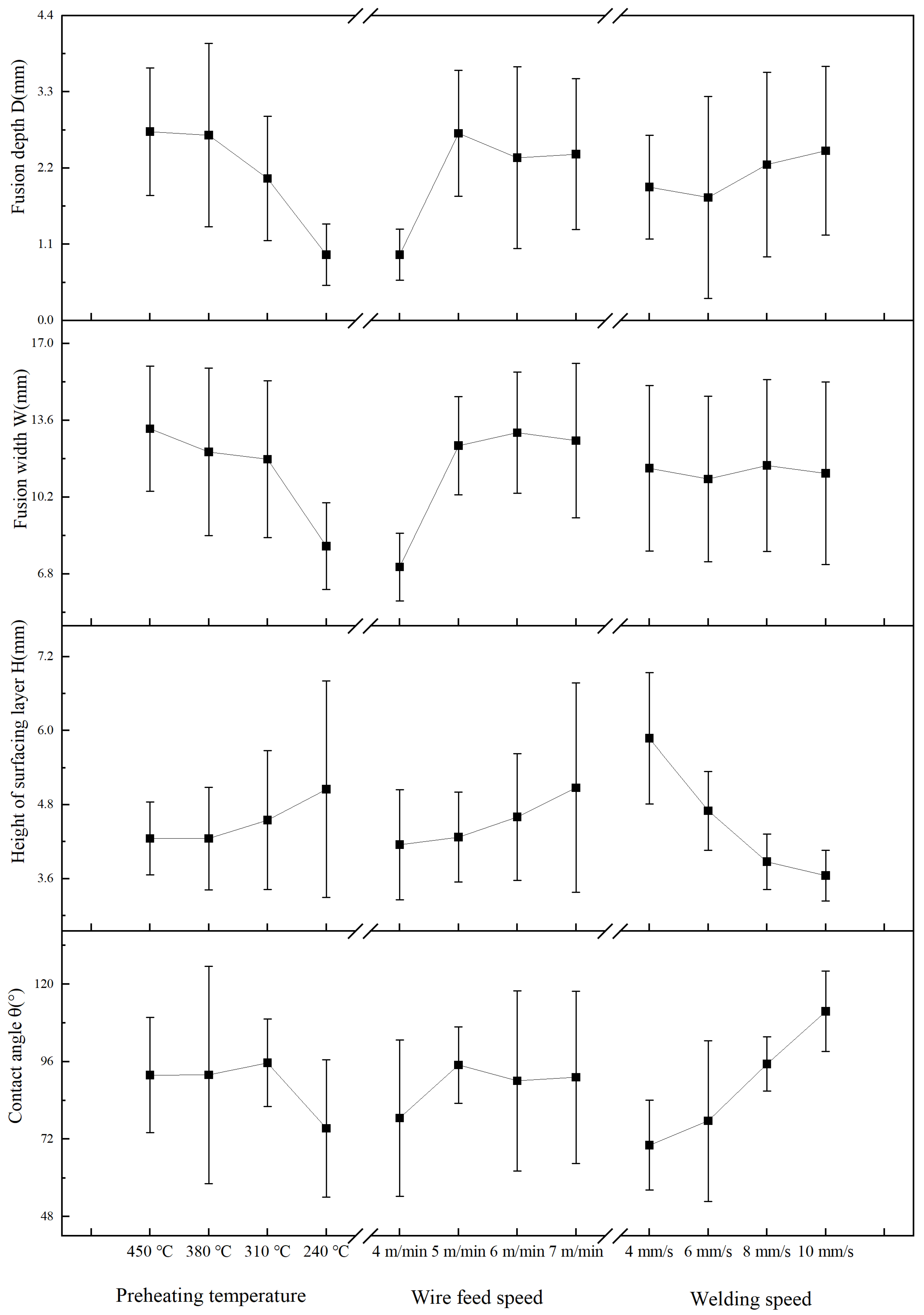
The contact angle, layer height of the surfacing layer, fusion width, and fusion depth with different repair parameters were measured, and the results are shown in Table 3. The results shown Table 3 were processed to obtain the average of the statistics at different levels and factors, as shown in Figure 5. It can be seen from Figure 5 that when the preheating temperature was 310–450 °C, the wire-feeding speed was 5–7 m/min, the welding speed was 8–10 mm/s, and the contact angle was larger. When the preheating temperature was 310–450 °C, the wire-feeding speed was 5–7 m/min, the welding speed was 6–10 mm/s, and the height of the surfacing layer was small. When the preheating temperature was 310–450 °C, the wire-feeding speed was 5–7 m/min, and the welding speed was 4–10 mm/s, the fusion width was larger. When the preheating temperature was 310–450 °C, the wire-feeding speed was 5–7 m/min, the welding speed was 8–10 mm/s, and the fusion depth is larger.
Table 3.
Measurement results of forming parameters of surfacing orthogonal experiment.
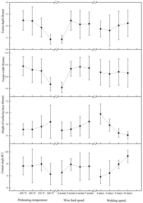
Figure 5.
Cross-section forming law of surfacing layer under different preheating temperatures, wire-feeding speeds, and welding speeds.
The preheating temperature has a significant effect on the contact angle, the height of the surfacing layer, the fusion width, and the fusion depth. When the preheating temperature is low, the spread of the melt on the substrate surface is poor. The contact angle is small, the height of the surfacing layer is high, and the penetration depth and width are small.
With the increase in the substrate preheating temperature, the melt fluidity is obviously improved, and the mixing degree between the base material and the filler metal is increased [18]. Sufficient mixing between the base material and the filler metal can effectively suppress the occurrence of unfused defects. Cui et al. showed that increasing the preheating temperature during friction stir welding of Q690 high-strength steel can reduce the wear of the stirring head, which shows that the preheating of the substrate also has the effect of softening the metal [19]. The substrate preheating also has a significant effect on the suppression of crack defects by reducing the heat dissipation temperature gradient and residual stress [20,21].
Welding speed has a more significant impact on the contact angle and height of the surface layer. As the welding speed increases, the contact angle significantly increases while the height of the surface layer significantly decreases. The welding speed is related to the volume of the weld per unit length. The greater the welding speed, the smaller the volume of the weld per unit length and the lower the height of the weld, which is beneficial for obtaining a contact angle greater than 90 degrees. The effect of welding speed on the contact angle is slightly complex. Zhang et al. showed that the contact angle decreased with the increase in welding speed [22], which is inconsistent with the conclusions of this study. Compared with the welding speed, preheating temperature and wire-feeding speed have a significant effect on the fusion width and fusion depth. With the increase in preheating temperature and wire-feeding speed, the fusion width and fusion depth increase significantly.
The wire-feeding speed is directly related to the welding current. The greater the wire-feeding speed, the greater the welding current and welding heat input. With the increase in the wire-feeding speed, the spreadability of the metal melt on the substrate surface shows an obvious improvement [23], and the contact angle increases [24]. When the wire-feeding speed increases, the amount of welding wire melting per unit time increases, resulting in an increase in the height of the surfacing layer. As the wire feed speed increases, the welding current increases and heat accumulation increases [25], resulting in an increase in the fusion width and depth. Variations in wire feed speed also affect pores and cracks. The increase in wire feed speed leads to an increase in heat input and a decrease in porosity [24]. Solidification crack sensitivity increases first and then decreases with the increase in wire feed speed [26].
CMT repair of surface defects of ZM6 cast magnesium alloy is similar to CMT multi-layer multi-channel welding, and the contact angle, height, fusion width, and fusion depth of each weld directly affect the weld fusion. As for the contact angle, the better the spread of the melt, the larger the contact angle, and the more conducive it is to forming. When the contact angle is more than 90°, unfused defects are less likely to occur. For the weld height, when the height of each weld is high, it is easy to produce defects such as cracks and incomplete fusion. For the fusion width, the greater the width, the more conducive it is to repair forming. For the fusion depth, the greater the penetration, the more conducive it is to repair forming, it decreases the likelihood of defects such as incomplete fusion. Therefore, in order to avoid incomplete fusion defects in the repair process, the contact angle of each weld should be greater than 90 degrees, the weld height should be as short as possible, and the fusion width and depth should be as large as possible.
Based on the above analysis, when the CMT process is used to repair the surface defects of ZM6 cast magnesium alloy, in order to ensure that there are no incomplete fusion defects, the feasible repair process window is as follows: the preheating temperature is 310–450 °C, the wire-feeding speed is 5–7 m/min, and the welding speed is 8–10 mm/s.
3.2. Analysis of arc Behavior and Droplet Characteristics under Different Repair Parameters
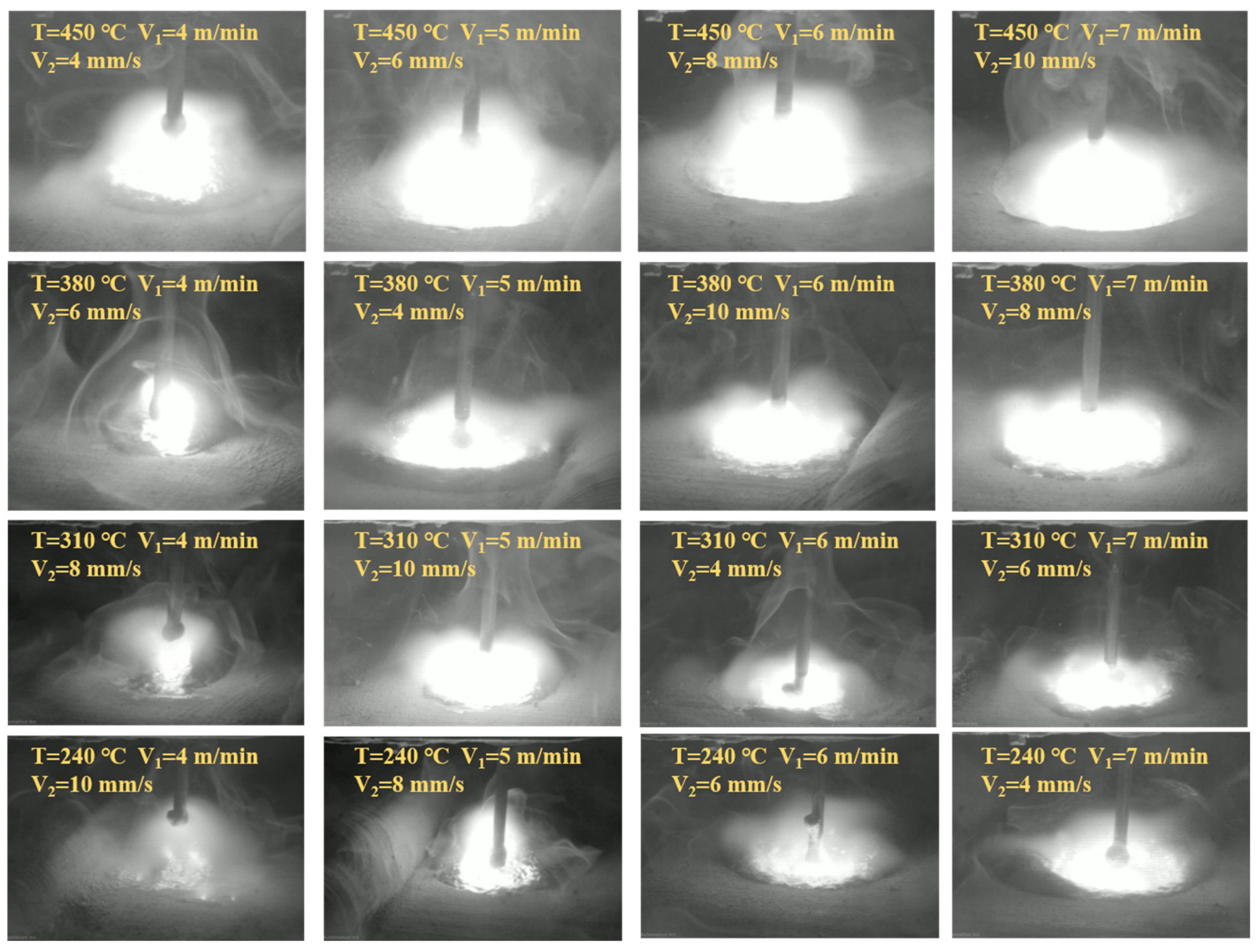
During the CMT welding process, the arc alternates between burning and extinguishing. When the short-circuit transition occurs, the arc is extinguished, and then the wire is mechanically drawn back and the arc is re-ignited. This section focuses on the analysis of the arc pattern and droplet characteristics of the arc’s stable combustion phase under different parameters, and the results are shown in Figure 6. It can be seen from the figure that the preheating temperature has a direct effect on the arc behavior and droplet size. When the preheating temperature is 240 °C, the surface temperature of the base material is low, the arc combustion is insufficient, the droplet volume at the end of the welding wire is large, and the droplet axis deviates from the axis of the welding wire. The reason why the droplet axis deviates from the wire axis is that the droplet is subjected to the reaction force generated by the evaporation of the droplet [27]. When the wire-feeding speed is 4 m/min and 5 m/min, the weld pool formed on the surface of the base material is shallow. With the increase in the preheating temperature of the base material, the arc combustion becomes more intense and the arc combustion is more stable. When the wire-feeding speed is small, the size of the droplet at the end of the welding wire is larger, and as the wire-feeding speed increases, the size of the droplet attached to the end of the welding wire gradually decreases. The preheating temperature and wire-feeding speed have a direct effect on the droplet transfer at the end of the wire. The surface tension and gravity of magnesium alloy at high temperature are very small, which makes it difficult for the droplet to separate from the end of the wire [28]. When the preheating temperature is higher, the arc plasma is more fully ionized and the arc burns violently. The arc temperature is higher and the electromagnetic force is larger, which makes it easier to promote the droplet transfer. When the wire-feeding speed increases, the welding current increases, and the electromagnetic force on the droplet also increases, which promotes the droplet transition and leads to the decrease of the droplet size [27,29]. When the preheating temperature is 310–450 °C and the wire-feeding speed is 5–7 m/min, the weld pool that forms on the surface of the base material under the action of the arc is obvious.
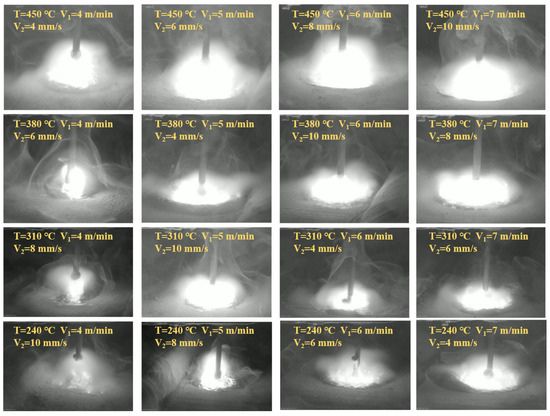
Figure 6.
Arc behavior and droplet characteristics with different preheating temperature, wire-feeding speed, and welding speed.
It can be seen from Figure 6 that with the increase in the substrate preheating temperature, the arc combustion becomes more intense and the arc brightness increases. This phenomenon is analyzed as follows:
Assuming that the arc plasma is in a state of local thermodynamic equilibrium, the gas ionization state can be expressed by the Saha Formula (1).
In the formula, α represents the ionization degree, z1 is the internal partition function of the ions, z is the internal partition function of the atoms, p is the pressure, me is the electron mass, h is Planck’s constant, k is Boltzmann’s constant, En is the nth quasi-potential energy, and T is the plasma temperature.
According to the Saha formula, the ionization degree of the gas increases with the increase in the plasma temperature. When the preheating temperature of the substrate increases gradually, the plasma temperature also increases gradually, the ionization degree of the gas also increases, and the arc combustion is more intense.
If the density distribution of particles in different energy states follows the Boltzmann distribution criterion, the intensity of the atomic spectral line satisfies the following Formula (2):
In the formula, N0 represents the density of state particles, gn is the statistical weight, Anm is the probability of a particle transitioning from the nth energy level to the mth energy level, λnm is the spectral wavelength when a particle transitions from the nth energy level to the mth energy level, and Z(T) is the internal distribution function of state particles.
According to the above formula, the main factors that cause the change in spectral intensity are the plasma temperature and the state particle density of the element. When the substrate preheating temperature increases, the arc plasma temperature increases, the plasma ionization degree also increases, and the arc plasma particle density also increases, resulting in the arc intensity also increasing with the increase in the substrate preheating temperature.
3.3. Effect of Welding Wire Stick-Out Length and Shielding Gas Flow on Weld Surface Forming
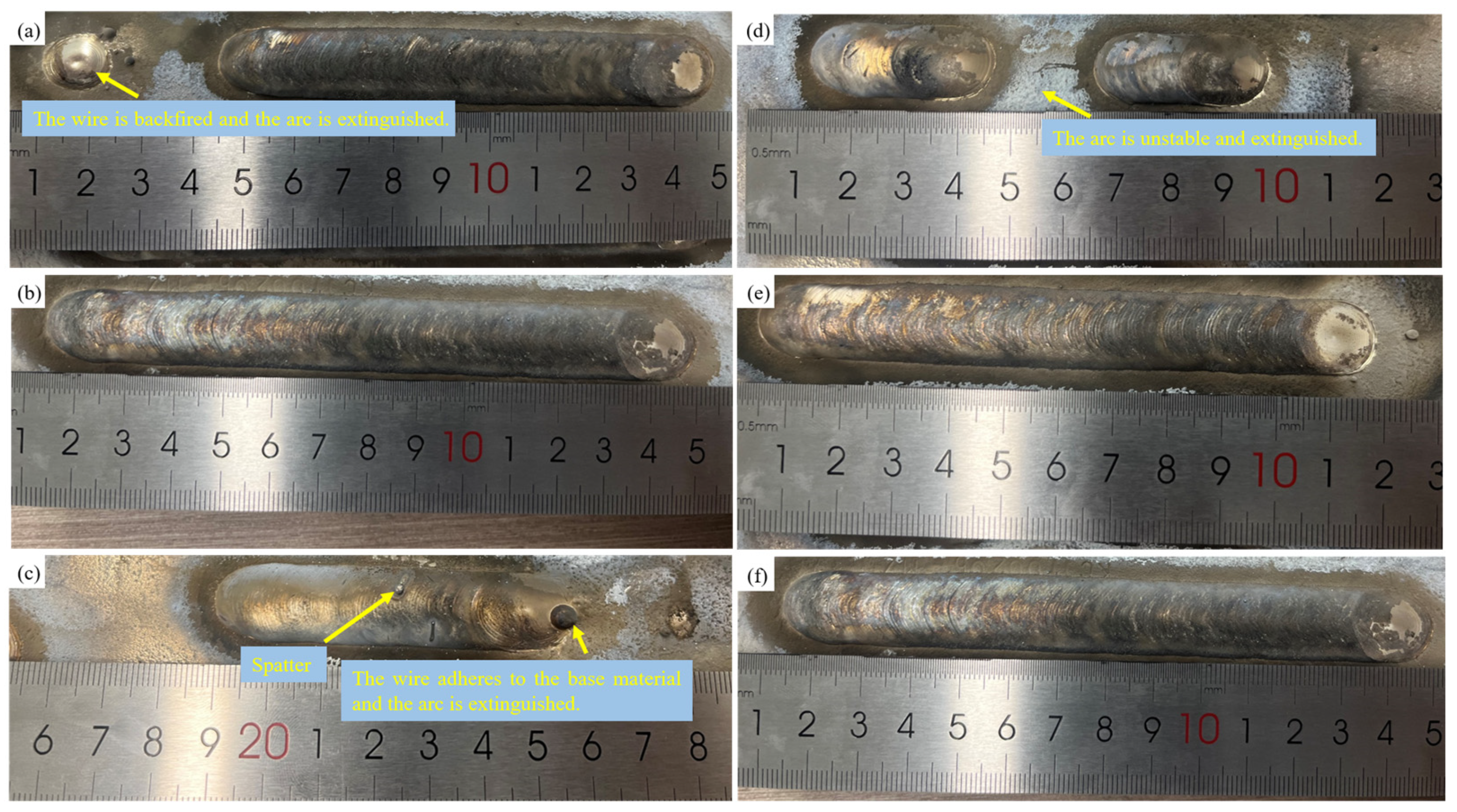
During CMT welding, the appropriate stick-out length and shielding gas flow rate should be selected. This part keeps other parameters unchanged, changes the stick-out length of welding wire and shielding gas flow rate, respectively, and studies the influence of wire stick-out length and shielding gas flow rate on weld surface formation. The results are shown in Figure 7. It can be seen from Figure 7a–c that when the stick-out length is 8 mm, although the weld formation is relatively uniform, the arc phenomenon of the conductive nozzle occurs during the welding process. This is due to the presence of a mechanical wire withdrawal process in the CMT welding process. When a short circuit transition occurs, the arc is extinguished and the wire is drawn back. When the stick-out length of the welding wire is short, the welding wire is closer to the edge of the conductive nozzle after being drawn back, and it is easy to form an arc between the conductive nozzle and the workpiece, resulting in welding interruption, thereby affecting the normal welding process. When the stick-out length is 12 mm, the surface shape of the weld is better, the arc is more stable during the welding process, and the arc-breaking phenomenon does not occur. When the stick-out length is 16 mm, the spatter is large in the welding process, the weld formation is uneven, and welding wire and the base material adhesion occurs during the welding process, resulting in the arc extinguishing. This is because when the stick-out length is large, the conductive length is large, the resistance is large, the actual welding current is reduced, and the fusion speed of the welding wire is reduced. Due to the constant wire-feeding speed, the melting speed of the welding wire is lower than the wire-feeding speed, and the welding wire is continuously elongated until it comes into contact with the base materials and adheres, resulting in arc breaking.

Figure 7.
Effect of wire stick-out length and shielding gas flow on welding stability: (a) stick-out length: 8 mm; (b) stick-out length: 12 mm; (c) stick-out length: 16 mm; (d) gas flow: 10 L/min; (e) gas flow: 20 L/min; (f) gas flow: 30 L/min.
The influence of shielding gas flow rate on weld formation is shown in Figure 7d–f. It can be seen from the figure that when the shielding gas flow rate is 10 L/min, the arc is unstable and easy to extinguish, which has resulted in an undercut and bulge. When the protective air flow is small, the air in the arc space cannot be effectively excluded, resulting in an increase in the ionization voltage of the arc space and a decrease in arc stability. When the gas flow rate is 20 L/min and 30 L/min, the surface of the weld is more uniform, and the weld surface has good gloss. Considering the cost of gas use and the effect of protection, the protective gas flow rate of 20 L/min is ideal. In summary, when CMT is used to weld or repair ZM6 cast magnesium alloy, it is ideal when the stick-out length of the welding wire is 12 mm and the protective gas flow rate is 20 L/min.
3.4. Effect of Repair Path on Surface-Defect Repair Forming of ZM6 Cast Magnesium Alloy
In addition to factors such as preheating temperature, wire-feeding speed, welding speed, stick-out length of the welding wire, and protective gas flow rate, the path of the arc (repair path) also has a significant impact on the repair formation. An unreasonable repair path may lead to incomplete defects in the repair area, so it is necessary to explore the effect of the repair path on the surface defect repair formation of ZM6 cast magnesium alloy. Five typical repair paths were designed, as shown in Figure 3, and the macroscopic formation after repair is shown in Figure 8. In terms of appearance morphology, the repair morphologies obtained using five different repair paths are similar, with no obvious differences. All five repair morphologies have noticeable quenching pits, and the area of the quenching pits is relatively large. This is due to the higher preheating temperature and wire-feeding speed, which result in better melt spreading properties. The repair area was cut open to obtain four vertical sections. After repairs using repair paths 1, 2, 4, and 5, the repair area is well fused with no internal incomplete defects. After repairs using repair path 3, there is a clear unfused defect at the center of the repair area. Furthermore, whether interlayer arc extinguishing and cleaning of the surface are performed does not significantly affect the formation.
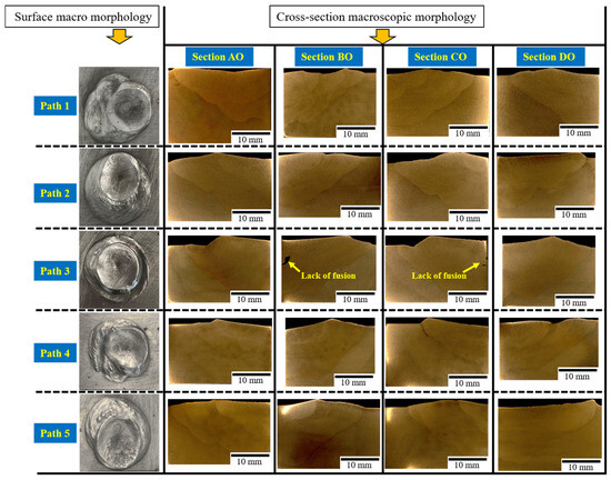
Figure 8.
Morphology of repair area obtained by five different repair paths.
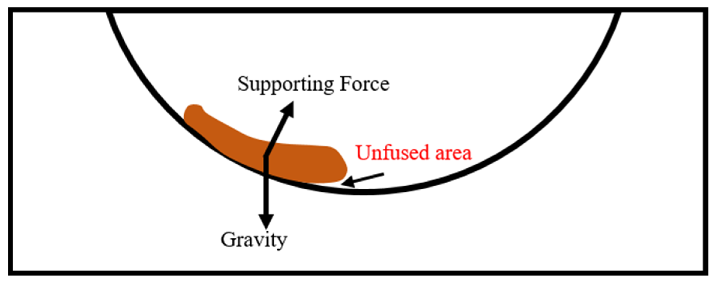
Repair path 3 is a rotational path from the periphery to the interior. When this path is applied for repair, there are unfused defects inside. The causes of these unfused defects are analyzed as follows: The shape of the repair area is a quarter spherical crown, and the repair surface has a certain slope. When the arc moves around the circle, the force diagram of the weld pool melt is shown in Figure 9. The weld pool melt is subjected to the combined effects of its own gravity and the supporting force of the side wall. Due to the certain slope of the defect side wall, the weld pool melt will flow down along the defect side wall. Under the action of the surface tension of the melt itself, the lower end of the melt shrinks into a spherical surface. In addition, there is no support effect on the melt from the bottom part of the weld pool melt, which ultimately leads to an unfused area at the bottom of the melt. After repairs using paths 2 and 5, which are also rotational repair paths, no unfused defects were found. This is because the repair sequence of paths 2 and 5 is different from that of path 3. The rotation direction of paths 2 and 5 is from the interior to the periphery. Although the weld pool melt will flow down when the arc rotates, the parts repaired first on the inside will provide support to the melt, preventing the occurrence of unfused defects.

Figure 9.
Schematic diagram of formation mechanism of unfused defect generated by rotating repair path.
Considering the convenience of using a robot to program the repair path, the repair area forming, and repair efficiency, it is better for the fourth repair path (continuous linear reciprocating welding repair) used to repair the surface defects of ZM6 cast magnesium alloy.
The surface defects of ZM6 cast magnesium alloy were repaired by a CMT welding method, and the repair quality was directly related to the forming and microstructure of the repair area. On the basis of obtaining a repair area without incomplete fusion defects, the repair process needs to be further optimized in subsequent research. For example, the welding torch swing can be used to stir the weld pool and refine the structure [30], and finally improve the mechanical properties.
4. Conclusions
- The preheating temperature of the base material has a great influence on the spreading behavior of the magnesium alloy melt on the surface of base material. When the preheating temperature of the base material is in the range of 310–450 °C, the magnesium alloy melt exhibits good spreading performance on the substrate surface, with a contact angle greater than 90°. The preheating temperature of the base material also greatly affects the stability of the arc. The higher the preheating temperature of the base material, the more stable the arc combustion.
- The greater the wire-feeding speed, the better the spreading behavior of the magnesium alloy melt on the surface of the base material, and the larger the contact angle. At the same time, the depth, width, and layer height of the weld also increase. Welding speed has a significant influence on the contact angle, layer height, and fusion depth. As the welding speed increases, both the contact angle and fusion depth increase, while the layer height decreases.
- The stick-out length of the welding wire has a direct influence on the stability of welding, and when the stick-out length of the welding wire is 12 mm, the welding process is stable. Compared with the rotating repair path, the repair area obtained by using the continuous straight reciprocating repair path is better shaped, without any unfused defects.
Author Contributions
Conceptualization, Z.C. (Zenghui Cai), F.S. and S.L.; methodology, Q.C.; formal analysis, Z.C. (Zhien Chen) and T.S.; investigation, Z.C. (Zhien Chen); resources, F.S.; writing—original draft preparation, Z.C. (Zenghui Cai) and Q.C.; writing—review and editing, Y.C. and X.C.; supervision, F.S., B.D. and S.L. All authors have read and agreed to the published version of the manuscript.
Funding
This research received no external funding.
Data Availability Statement
The original contributions presented in the study are included in the article, further inquiries can be directed to the corresponding authors.
Conflicts of Interest
Authors Zenghui Cai, Faming Shen, Yanfeng Cui, and Tongge Shao were employed by the company AECC Harbin Dong’an Engine Co., Ltd. The remaining authors declare that the research was conducted in the absence of any commercial or financial relationships that could be construed as a potential conflict of interest.
References
- Volodin, V.; Kenzhaliyev, B.; Trebukhov, S.; Nitsenko, A.; Linnik, X.; Trebukhov, A. On the problem of the distillation separation of secondary alloys of magnesium with zinc and magnesium with cadmium. Metals 2024, 14, 671. [Google Scholar] [CrossRef]
- Chen, Y.; Zhou, W.B.; Guo, L.T.; Yang, C.L. A review and development tendency of welding repair technology for cast magnesium alloy. Mater. Rep. 2020, 34, 15126–15131. [Google Scholar] [CrossRef]
- Chen, Y.; Guo, L.T.; Qi, T.F.; Yang, C.L. Repair process of magnesium alloy casting by He-Ar mixed gas TIG welding. Trans. China Weld. Inst. 2021, 42, 35–41. [Google Scholar] [CrossRef]
- Zhang, Z.D.; Yang, J.H.; Song, G.; Wang, J.N. Study on A-TIG repair welding for the cast magnesium alloy. Trans. China Weld. Inst. 2017, 38, 87–90. [Google Scholar]
- Zhang, Z.D.; Cao, A.C.; Liu, J.M.; Liu, J. Study on A-TIG multilayer repair welding process and properties of cast magnesium alloy ZM5. Weld. Technol. 2016, 45, 4–8. [Google Scholar] [CrossRef]
- Kang, H.Y. Comparative analysis of TIG and A-TIG repair welding process of cast magnesium alloy. China South. Agric. Mach. 2020, 51, 120. [Google Scholar]
- Zhang, X.G.; Wang, W.Q.; Zheng, X.; Chen, J.; Shen, F.M.; Li, H.M.; Sun, D.Q. Weld characteristics, microstructure and mechanical properties of argon arc welding repair joints for zm6 cast magnesium alloy. Electr. Weld. Mach. 2023, 53, 23–27. [Google Scholar] [CrossRef]
- Wang, X.; Yang, C.; Feng, J.C. Research on TIG repairing technology for ZM6 magnesium alloy casting. Trans. China Weld. Inst. 2010, 31, 33–36. [Google Scholar]
- Yang, H.W.; Wang, Y.S. Defect repair welding technology of magnesium alloy castings. Weld. Technol. 2004, 33, 32–33. [Google Scholar] [CrossRef]
- Shalomeev, V.; Tabunshchyk, G.; Greshta, V.; Korniejenko, K.; Duarte Guigou, M.; Parzych, S. Casting welding from magnesium alloy using filler materials that contain scandium. Materials 2022, 15, 4213. [Google Scholar] [CrossRef]
- Assar, A.; Nami, B.; Arab, N.B.M.; Khoubrou, I. Effect of heat input of TIG repair welding on microstructure and mechanical properties of cast AZ91 magnesium alloy. Weld. World 2021, 65, 1131–1143. [Google Scholar] [CrossRef]
- Kocurek, R.; Adamiec, J. The repair welding technology of casts magnesium alloy QE22. Solid State Phenom. 2014, 212, 81–86. [Google Scholar] [CrossRef]
- Adamiec, J. Repairing the WE43 magnesium cast alloys. Solid State Phenom. 2011, 176, 99–106. [Google Scholar] [CrossRef]
- Bendis, A.; Hrdina, J.; Teichman, J. Fatigue strength of repaired magnesium alloy castings by TIG welding. Weld. Int. 1989, 3, 817–821. [Google Scholar] [CrossRef]
- Adamiec, J.; Roskosz, S.; Jarosz, R. Repair of magnesium alloy castings by means of welding and pad welding. J. Achiev. Mater. Manuf. Eng. 2007, 22, 21–24. [Google Scholar]
- Liu, H.Y.; Wang, S.; Liang, J.; Hu, H.; Li, Q.T.; Chen, H.R. Effect of lanthanum oxide on the microstructure and properties of Ti-6Al-4V alloy during CMT-additive manufacturing. Crystals 2023, 13, 515. [Google Scholar] [CrossRef]
- Xu, F.; Wu, D.Y.; Zhang, C.; Yang, H.; Zhang, Z.R.; Shen, J.Q. Stability analysis of the cold metal transfer deposition process of AZ91 magnesium alloy. Weld. Technol. 2024, 53, 49–54. [Google Scholar] [CrossRef]
- Samadi, N.; Aval, H.J. Formation of nickel aluminide in situ via dual-wire arc cladding. Metallogr. Microstruct. Anal. 2024. [Google Scholar] [CrossRef]
- Cui, H.B.; Hu, Y.W.; Chen, S.; Wang, C.X.; Tang, X. Control of the microstructural evolution and toughness of welded joints by preheating and subsequent cooling in hybrid friction stir welding of Q960 high strength steel. Mater. Today Commun. 2024, 39, 109363. [Google Scholar] [CrossRef]
- Burapa, R.; Oo, H.Z.; Sangwiman, W.; Muangjunburee, P. Influences of preheating parameters on the quality of weld by thermite rail welding. Mater. Res. Express 2024, 11, 066507. [Google Scholar] [CrossRef]
- Chen, X.W.; Tang, S.; Xie, W.L.; Zhang, M.; Song, H.; Ran, Q.Z.; Zhang, D.F. Study on the effect of preheating temperature on residual stress in laser arc composite welding of dissimilar aluminum alloys. JOM 2024, 76, 3832–3839. [Google Scholar] [CrossRef]
- Zhang, H.; Hu, S.S.; Wang, Z.J.; Liang, Y. The effect of welding speed on microstructures of cold metal transfer deposited AZ31 magnesium alloy clad. Mater. Des. 2015, 86, 894–901. [Google Scholar] [CrossRef]
- Du, G.D.; Xing, Y.F.; Yin, C.Y. Process optimization of cold metal transfer plug welding of aluminum AA6061-T6-to-galvanized DP590 steel based on orthogonal experiment method. Mater. Sci. 2019, 25, 207–213. [Google Scholar] [CrossRef]
- Zhang, Z.Q.; Yan, J.P.; Lu, X.C.; Zhang, T.G.; Wang, H. Optimization of porosity and surface roughness of CMT-P wire arc additive manufacturing of AA2024 using response surface methodology and NSGA-II. J. Mater. Res. Technol. 2023, 24, 6923–6941. [Google Scholar] [CrossRef]
- Wu, W.; Xue, J.X.; Zhang, Z.H.; Ren, X.H.; Xie, B. Process optimization on multilayer morphology during 316L double-wire CMT+P deposition process. Metals 2019, 9, 1334. [Google Scholar] [CrossRef]
- Huang, L.; Chen, X.Z.; Konovalov, S.; Siddiquee, A.N.; Lu, G.; Pan, X.M. The effect of wire feeding speed on solidification cracking of CMT welding for Al-Si alloys. Metals 2021, 11, 267. [Google Scholar] [CrossRef]
- Hu, S.S.; Zhang, H.; Wang, Z.J.; Liang, Y.; Liu, Y.Q. The arc characteristics of cold metal transfer welding with AZ31magnesium alloy wire. J. Manuf. Process. 2016, 24, 298–306. [Google Scholar] [CrossRef]
- Song, G.; Wang, P.; Liu, L.M. Study on ac-PMIG welding of AZ31B magnesium alloy. Sci. Technol. Weld. Join. 2010, 15, 219–224. [Google Scholar] [CrossRef]
- Song, G.; Wang, P. Pulsed MIG welding of AZ31B magnesium alloy. Mater. Sci. Technol. 2011, 27, 519–524. [Google Scholar] [CrossRef]
- Gonela, K.K.; Vijayavarman, C.; Palanivel, M.; Mariappan, L.; Ramasubramanian, L.N.; Kannan, A.R. Effect of robotic weaving motion on mechanical and microstructural characteristics of wire arc additively manufactured NiTi shape memory alloy. Int. J. Mater. Res. 2023, 114, 947–954. [Google Scholar] [CrossRef]


Disclaimer/Publisher’s Note: The statements, opinions and data contained in all publications are solely those of the individual author(s) and contributor(s) and not of MDPI and/or the editor(s). MDPI and/or the editor(s) disclaim responsibility for any injury to people or property resulting from any ideas, methods, instructions or products referred to in the content. |
© 2024 by the authors. Licensee MDPI, Basel, Switzerland. This article is an open access article distributed under the terms and conditions of the Creative Commons Attribution (CC BY) license (https://creativecommons.org/licenses/by/4.0/).