Article

Effect of Solution and Aging Heat Treatment on the Microstructure and Mechanical Properties of Inconel 625 Deposited Metal

School of Materials Science and Engineering, Shenyang University of Technology, Shenyang 110870, China
*
Author to whom correspondence should be addressed.
Crystals 2024, 14(9), 764; https://doi.org/10.3390/cryst14090764
Submission received: 7 August 2024 / Revised: 18 August 2024 / Accepted: 20 August 2024 / Published: 28 August 2024
(This article belongs to the Section Crystalline Metals and Alloys)

Abstract

:
Inconel 625 deposited metal was prepared by gas metal arc welding. The solid solution treatment temperature was set at 1140 °C for 4 h using the DSC test method, followed by secondary aging at 750 °C/4 h and 650 °C/24 h. The specimens in the prepared state and after heat treatment were subjected to high temperature tensile at 600 °C, respectively. The fracture morphology, thermal deformation behavior, and strengthening mechanism of the samples in different states were analyzed. The results showed that the stress–strain curves of the deposited metals exhibited obvious work-hardening behavior at 600 °C. The solid solution and aging heat-treated samples have higher tensile and yield strength, but the plasticity is obviously lower than that of the deposited metal. It was also found that the γ″ phase and M23C6 carbides, as well as the continuous stacking faults in the alloy, were the main reasons for the increase in tensile strength of the solution and aging heat-treated sample.

1. Introduction

Ultra-supercritical (USC) coal-fired power generation technology has many advantages such as low energy consumption, low emissions, and high efficiency. It is regarded as the most advanced clean coal-fired power generation technology in the world, with significant energy-saving and environmental improvement effects. Generally, the primary steam pressure is usually 24.1–31 MPa, and the central steam/reheated steam temperature is 580 °C–600 °C/580 °C–610 °C. The generator set is defined as an efficient supercritical generator set, commonly referred to as an ultra-supercritical generator set. However, the improvement of the generator set parameters is subject to the development and manufacture of high-temperature resistant materials, and with the improvement of steam parameters, more high-temperature resistant materials must be applied. Currently, the material commonly used in the design and practice of ultra-supercritical coal-fired boilers with steam parameters of 600 °C is Super304H austenitic stainless steel, and the welding of this material mainly uses nickel-based welding materials with better high-temperature performance. There are various types of nickel-based superalloys, among which the Inconel 625 nickel-based alloy with excellent tensile strength, weldability, corrosion resistance, and oxidation resistance is widely used in various projects such as aerospace and gas turbine engines [1,2,3,4]. Therefore, research on its welding performance, rapid forming process, solution treatment, and high-temperature corrosion behavior has become a hotspot [5,6]. The gas metal arc welding (GMAW) process has become a valuable research process due to its low cost, high deposition rate, strong automation ability, and appropriate protection of weld metal by inert gas. Recently, it has received extensive research [7,8,9,10]. The Inconel filler wires are well known for their reliability on dissimilar welds, as they can accommodate differences in chemical composition and thermal expansion between dissimilar metals [11,12].
Nevertheless, the high heat input in the welding process will lead to grain growth, and the segregation of solute elements in the welding solidification process will increase the possibility of secondary phase precipitation, which will have unfavorable effects on the properties. Many researchers have found [13,14,15,16,17] that heat treatment has a significant effect on the microstructure of Inconel 625 superalloy. The heat treatment process can not only change the grain size of the alloy, the type and quantity of precipitated phases, as well as the dissolution and precipitation of secondary phases, but also alter the grain boundary state. Therefore, metals deposited after different heat treatment processes will have different microstructure morphology and composition distribution, thus possessing various properties and applications. Mathieu Terner [18] discussed the effects of different heat treatments on a superalloy produced by LPBF and showed that the particular microstructure of that alloy can be transformed to accommodate particular applications. Yunlong Hu [19] conducted heat treatment on Inconel 625 deposited metal in different ways and found the γ″ phase was only observed in samples that had undergone solid solution and aging treatments. The formation of the γ″ phase enormously enhances the strength, but reduces the elongation. G. P. Dinda [20] recognized the microstructure evolution of Inconel 625 alloy after deposition and heat treatment. The results showed that Inconel 625 prepared by DED had high thermal stability, stable dendritic substructure below 1000 °C, and complete recrystallization occurred around 1200 °C. Marchese [21] found the ultimate tensile strength (UTS) of Inconel 625 alloy parts produced by LPBF increased by 180 MPa after direct aging at 700 °C for 24 h. Safarzade et al. [22] studied the effect of heat treatment on the properties of the Inconel 625 alloy manufactured by GMAW process, and found that solution heat treatment had little impact on tensile strength, but increased the hardness and yield strength, while reducing elongation. However, aging heat treatment resulted in the formation of the γ″ phase and M23C6 carbides at grain boundaries, but decreased the mechanical properties of the alloy. It has been found [23] that the yield strength of Inconel 625 alloy prepared by directed energy deposition decreased with increasing solution temperature, but the elongation increased. Mostafaei et al. [24] confirmed that aging treatment led to the formation of intermetallic phases, such as Ni3Nb and Ni2 (Cr, Mo), as well as some carbides.
Heat treatment is an important method to improve the properties of Inconel 625 alloys. The heat treatment process not only changes the microstructure of the alloy but also has a significant impact on its mechanical properties [25,26,27]. Although many studies have focused on evaluating the effects of heat treatment processes on the microstructure and mechanical properties of Inconel 625 deposited metal, the optimal heat treatment of Inconel 625 deposited metal manufactured by the most traditional GMAW process has been less studied. In this paper, the GMAW process is used to weld Inconel 625 flux-cored wire, the initial melting temperature of the metal is tested by the differential scanning calorimetry method, and through the comparison of different solid solution temperatures and times, the optimal heat treatment process for the Inconel 625 molten metal under the working condition of 600 °C is finally determined, and its strengthening mechanism is studied. These results can provide some theoretical support for the application of Inconel 625 flux-cored wire in ultra-supercritical generating units.

2. Experiment

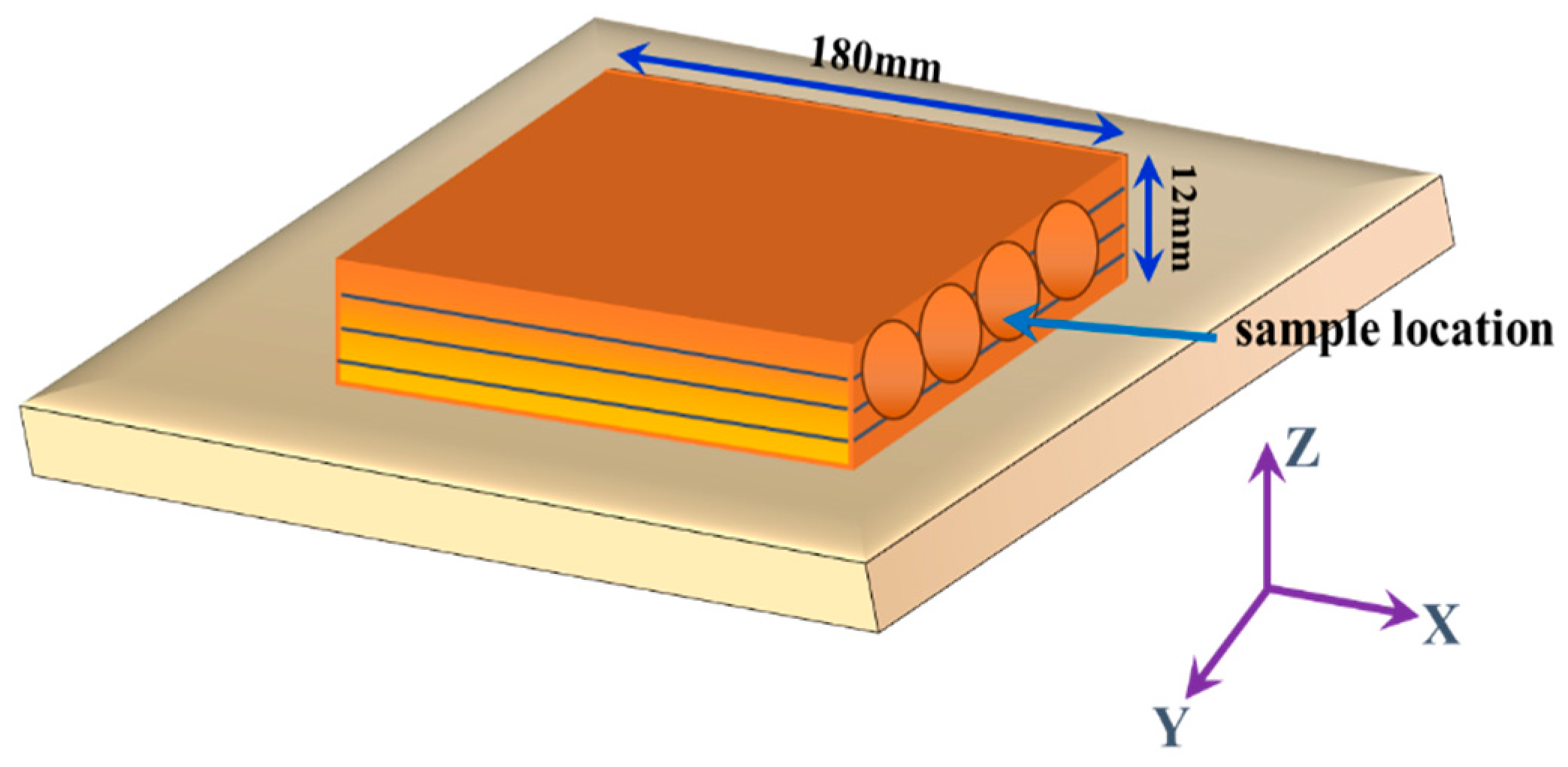
2.1. Material Preparation

The experiment selected Inconel 625 flux-cored welding wire with a diameter of 1.2 mm, which has the nominal composition (in wt. %) of 0.1C, 0.55Mn, 4.5Fe, 0.5Si, 0.5Cu, 0.2Ti, 3.5 < (Nb + Ta) < 4.15, 8.5Mo, 21~23Cr, and the rest being Ni. A specimen of 180 mm × 100 mm × 12 mm was prepared by overlaying Inconel 625 flux-cored welding wire on the surface of Super304H austenitic stainless steel using the YD-500FR2 GMAW welding machine. The welding voltage is 25 V and the current is 180 A. The automatic welding gun is manufactured in the laboratory and the welding speed is about 250 mm/min. Each pass is in the opposite direction to the previous pass, and the temperature of the intermediate layer should not exceed 150 °C during the welding process. The shielding gas used in this experiment is a mixture of 97% Ar + 3% N2. The surfacing layer consists of 4 layers with a height of 12 mm. In order to reduce the dilution rate during overlay, the overlay is set to 4 layers (approx. 12 mm). Tensile specimens are taken as close as possible to the upper surface and in the same direction as the overlay. The sample diagram is shown in Figure 1, and the dimensions of the stretched sample are shown in Figure 2.

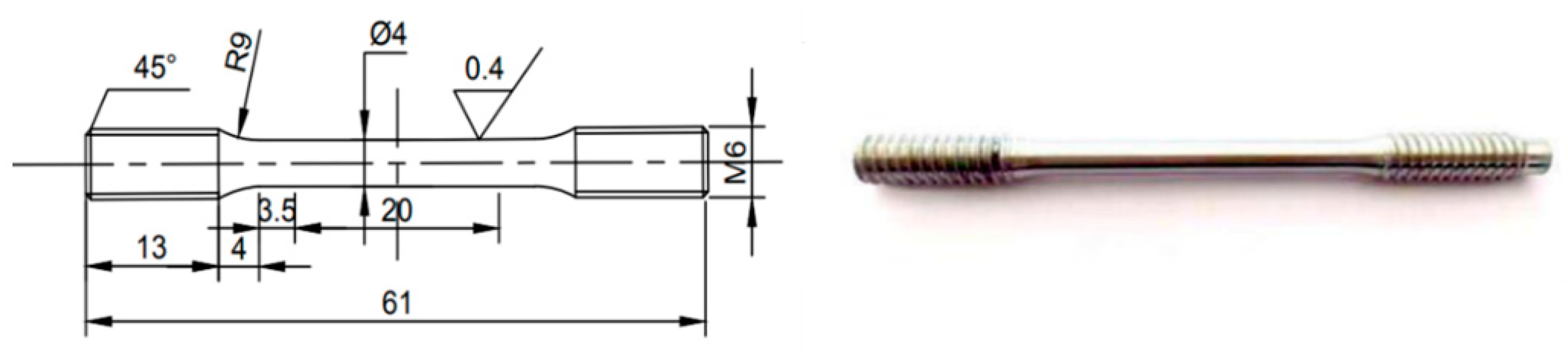
2.2. Experimental Methods

Differential scanning calorimetry (DSC) was analyzed on the as-welded Inconel 625 deposited metal to determine its solution temperature. Extracted dimensions from deposited alloy as Φ 3 mm × 2 mm columnar DSC sample, removed oxide scale with sandpaper, and then cleaned with ultrasound for 5 min. Using the THEMES comprehensive analyzer, a protective atmosphere with an argon flow rate of 20 mL/min was used, and the container was an alumina dry pot. The processed sample was put into an aluminum oxide dry pot protected by argon gas, with a testing temperature range of 800 °C–1400 °C and a heating rate of 10 °C/min. The solid solution heat treatment of the sample was carried out using a muffle furnace with an accuracy of ±3 °C. In addition, when the temperature was below 600 °C, the heating rate was 10 °C/min, and between 600 °C and 1400 °C, the heating rate was 2 °C/min. The samples received a complete heat treatment of 1140 °C/4 h WC + 750 °C/4 h AC + 650 °C/24 h AC (WC: water cooling, AC: air cooling).
High-temperature tensile tests were conducted on two states of the Inconel 625 deposited metal specimens (after this referred to as AWs) and the solution and aging specimens (starting now referred to as SAs). Used an MST Landmark 370.10 microcomputer controlled electro-hydraulic servo testing machine to test the high-temperature mechanical properties of the samples under different states. The samples were heated to 600 °C at a rate of 1 °C/s, then maintained for 10 min before testing. Evaluated the thermal field uniformity using three K-type thermocouples distributed along the gauge length of the specimens. Took three parallel samples from each temperature group to ensure reduction of errors, and took the average value of each group as the final data. The calculation formula is as follows:
Δ x = ( x m a x x m i n ) x m a x × 100 %
where x represents either the yield stress (YS), the ultimate tensile strength (UTS), or the elongation (δ). The radial temperature difference of the stretched sample should not exceed ±2 °C during the stretching process.

2.3. Characterization

The phase composition of the Inconel 625 deposited metal was characterized by an X−ray diffractometer, model XRD−7000, and with the specific parameters of a pure Cu target, a tube voltage of 40 KV, a current of 30 mA, a step length of 2 degree/min, and a scanning range of 20°–80°. Polished samples were etched with aqua regia (HCl:HNO3 = 3:1) for 45 s at room temperature. Microstructures of the samples were observed by optical (OLYMPUS BX51M, Tokyo, Japan) and scanning electron (SEM, S−3400N, Hitachi, Japan) microscopes equipped with an energy dispersive spectroscopy (EDS SAMX) analyzer. In order to clearly observe the microstructure and dislocation morphology of the alloy, TJ100-SE electrolytic double spray diluter was used to prepare transmission samples. The solution was a mixture of ethanol and perchloric acid with a volume ratio of 9:1. The temperature was around −25 °C, the current was 120 mA, and the voltage was 35 V. In this study, all transmission samples were observed using JEM−2100 transmission electron microscopy, with an acceleration voltage of 200 kV.

3. Results

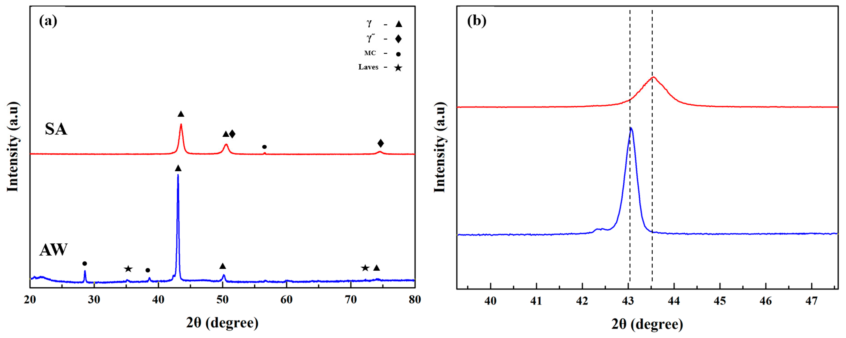
3.1. Alloy Characteristic Temperature and Heat Treatment
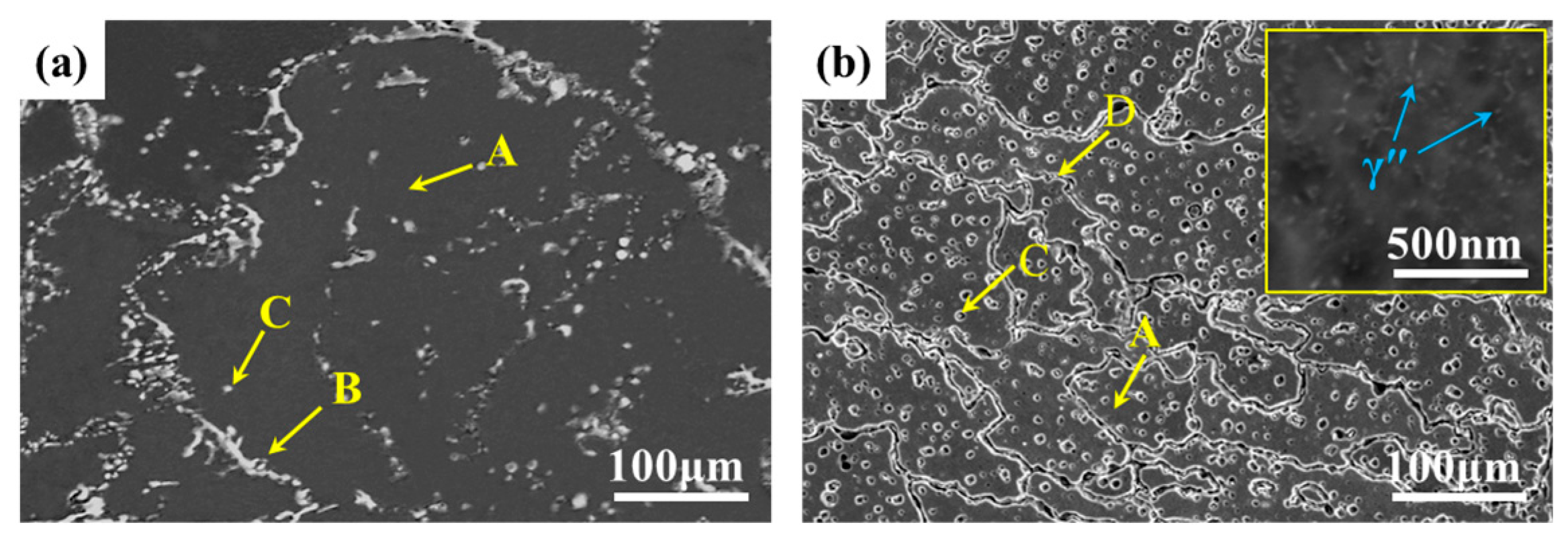
It can be seen from the DSC curve that there are three apparent thermal reaction zones on the heating curve (Figure 3). Depending on the intensity and location of the thermal reaction zone, the thermal reaction zone corresponds to the reaction of the γʹ phase dissolved in the γ matrix. The strength of the second thermal reaction zone is more significant, and it is the temperature at which the solid phase in the alloy begins to transform into the liquid phase, that is, the initial melting temperature of the alloy (1147 °C). The most prominent peak on the curve corresponds to the melting of the gamma phase (1278 °C), which is the main endothermic reaction throughout the entire endothermic process. Therefore, according to the DSC curve, the initial melting temperature of the deposited metal for welding Inconel 625 can be determined to be approximately 1147 °C.
To improve the efficiency of solution treatment as much as possible without causing initial melting of the alloy, and considering the fluctuation of furnace temperature during the solution treatment process, the solution treatment temperature of the Inconel 625 deposited metal was set to 1140 °C. In order to determine whether this temperature can be defined as the optimum heat treatment temperature, the tensile strength of the material at different solution temperatures was compared, and at the same time, tensile tests were carried out on the samples with different solution times at 1140 °C. The final experimental results are shown in Figure 4. It can be seen that the optimum solid solution temperature of Inconel 625 deposited metal is 1140 °C, and the solution time is set at 4 h. According to the experimental data, while referring to the relevant literature [19,28], the alloy’s solid solution treatment is ultimately set at a solution temperature of 1140 °C, and two levels of aging (1140 °C/4 h WC + 750 °C/4 h AC + 650 °C/24 h AC (WC: water cooling, AC: air cooling).

3.2. Microstructure

X-ray diffraction (XRD) patterns of two states are shown in Figure 5. Ni-based solid solutions with FCC crystal structure (00–003–1016) were detected in all samples. XRD results show that the AW specimen comprised γ matrix, MC carbide, and Laves phase. According to Figure 5a, it can be seen that after heat treatment, the Laves phase disappears and precipitates simultaneously into the γ″ phase. This indicates that the Laves phase in the AW sample has dissolved after heat treatment. The peak diffraction angle at 2θ = 43.08° (111) in the as-welded deposited metal moves to the higher direction of 2θ = 43.62° (Figure 5b). This shift of XRD peak position is ascribable to the change of Ni–FCC structure lattice parameters.
The SEM morphology of the Inconel 625 deposited metal sample is shown in Figure 6a. In the SEM image, it can be seen that there are unevenly distributed precipitates in the AW sample, and continuous precipitates can be seen at the grain boundaries (Figure 6a). EDS analysis shows that the dendrite core is rich in Ni and Cr but the interdendritic region has high contents of Mo, Nb, and C elements. Therefore, the segregation of Mo, Nb, and C in the interdendritic region leads to the formation of secondary phases. The EDS results of the sample at 600 °C are shown in Table 1. It can be seen that the matrix (point A) is a Ni-based solid solution containing Cr, Nb, Fe, and Mo elements. In addition, the contents of Ni and Cr in the bright irregular phase (point B) decreased significantly, while the Nb, Mo, and Ti increased significantly. The content of Nb and Mo in points B and C is higher than in point A. As shown in Table 1, the Ni + Cr + Fe content and Nb + Mo + Ti content of the bright phase marked with point B are 68.3 at% and 32.1 at%, consistent with the A2B structure of the Laves phase. According to the EDS spectrum, the nanoscale spherical particles (C position) precipitated from the tissue were carbides. TEM was used to confirm the type of carbide, and the results are shown in Figure 6a. It shows the bright field photo of a nanoscale precipitate in the welded microstructure and the selection diffraction pattern. According to the calibration analysis results of the diffraction spots, the ellipsoidal precipitate is NbC, whose size is about 300 nm.
Figure 6b shows the SEM image of the SA sample, indicating that the irregular second phase at the grain boundary has already dissolved in the matrix. There are many particles in the grains. The EDS results (Table 1) of these particles show high Nb and C contents, which are Nb-rich MC carbides formed in the grains after heat treatment. The experimental results show that after solid solution and aging heat treatment, the residual substances in the grains can be more uniform, forming many small precipitates at the grain boundaries. In addition, many small uneven distribution γ″ phases with the size of 10–30 nm were precipitated in the SA sample (Figure 6b). To accurately infer the discontinuous elongated phase formed along the grain boundary, TEM was used to detect it further and confirmed that it was a Cr-rich M23C6 phase precipitated at the grain boundary, with a size of about 200 nm (Figure 7b). The study [29] shows that more carbides precipitated at the grain boundary is conducive to improving the mechanical properties of the sample.
EBSD analysis can reveal the grain structure of the AW and SA samples (Figure 8). In both states, the grains arranged in the direction of construction (vertical plane). The microstructure of the AW specimen on the vertical plane is fine dendrite and columnar grain with sizes of about 10~300 µm (Figure 8a). The SA sample began to exhibit equiaxed grains, indicating a recrystallization process. However, there were still elongated grains in the vertical plane, with sizes of 10~150 µm (Figure 8b). It was obvious that the SA sample had a finer grain microstructure. The solid solution treatment produces a recrystallized structure, eliminating the fine dendritic and columnar grain structures of the AW sample, and begins to form equiaxed grains, which is believed to lead to more isotropic mechanical properties [28]. In addition, the number of low-angle grain boundaries (θ < the volume fraction of 15°) is higher than that of high-angle grain boundaries (θ > volume fraction of 15°). The low-angle grain boundaries of the SA samples are more than those of the as-deposited specifications, and the maximum texture intensity reaches 14.37, as shown in Figure 8b.

3.3. High-Temperature Mechanical Properties

The tensile properties in two different states are shown in Figure 9. The figure shows the stress-strain curve at 600 °C. The figure shows that the tensile stress-strain curves of the Inconel 625 deposited metal exhibit an apparent work hardening behavior after yielding to alloy fracture. After the heat treatment, the tensile stress-strain curve of the alloy obviously slows down after the yield, the work hardening behavior obviously weakens, and the stress gradually increases until the alloy breaks. The work hardening index (n) and tensile strength of the Inconel 625 deposited metal in different states can be obtained from the stress-strain curve. We used the Hollomon’s empirical formula to obtain the work hardening index:
S = ken
It can be used to characterize the strain-strengthening ability of alloys during the uniform plastic flow stage (i.e., the stage where the true stress-strain curve of the alloy moves from the yield point to the maximum load point). The greater the value of n, the more pronounced the strain work hardening, indicating that the stronger the resistance of the alloy to plastic deformation, the easier the alloy gives in to uniform deformation.
The yield strength, tensile strength, elongation, and work hardening index of Inconel 625 deposited metal in two states are shown in Table 2. You can see that the AW sample has a smaller n value. According to Table 2, compared with the welding state at 600 °C, the elongation (EL) and shrinkage (R/A) of the specimens after heat treatment decreased by about 22% and 18%, respectively.
The fracture characteristics and longitudinal profile of the sample after a high-temperature tensile test are shown in Figure 10. The fracture mode of the overlay layer is a ductile fracture, with a large number of ductile dimples and a small amount of tearing edges at the fracture site. Ductile dimples are a typical form of ductile fracture. From a macro point of view, the fracture surface of the AW sample is relatively rough, and a slight necking occurs (Figure 10a). There is a fractured carbide precipitated phase in the dimple of the alloy fracture (Figure 10c,e). To study the crack propagation path, scanning electron microscopy was used to observe the longitudinal section of the fracture (Figure 10g,h). This confirms that the 600 °C metal fracture is a mixed mechanism; the cracks have both intergranular and transgranular growth directions.
The fracture morphology of the SA sample is similar to that of the AW sample. As shown in Figure 10b, the overall surface of the fracture is flatter and there is no obvious necking phenomenon. There are a large number of ductile dimples (Figure 10d) at the fracture surface, with a small number of fragmented carbides distributed on the surface, but the size is significantly smaller (Figure 10f), and there are also some planes (Figure 10d) distributed at the fracture surface, which are usually considered to be generated by dislocations sliding along the {111} plane. In addition, there are some microcracks near the sliding surface (Figure 10d). Therefore, it can be inferred that the fracture of the SA sample may be caused by stress concentration at grain boundaries caused by the slip of dislocations along the {111} surface [30]. The longitudinal cross-section of the sample fracture (Figure 10h) indicates that the cracks in the sample are both along the direction of crystal extension and through the crystal extension. Therefore, the fracture mechanism of this type of crack is also a mixed-type mechanism.
After tensile fracture at 600 °C, dislocations entangled near grain boundaries can be observed in the microstructure of the AW sample (Figure 11a). Many dislocations have accumulated in the matrix channels, leading to local deformation of the alloy. After tensile deformation, the distribution of dislocations in the microstructure is uneven. The density of dislocations improves rapidly near the grain boundaries. The dislocations entangle rapidly and finally transform the cellular structure. After solid solution and aging heat treatment, dislocations in the tissue migrate, releasing distorted energy in the tissue due to thermal driving force. As shown in Figure 11b, the microstructure is composed not only of fault entanglement near grain boundaries, but also of a/2 <110> dislocations that cut γ′ precipitates, as well as continuous layering of matrix channels and precipitates (continuous layering). Due to the uneven distribution of dislocations in the microstructure, local stress concentration occurs in the sample.

4. Discussion

On account of the segregation of elements such as Nb and Mo in the solidification process of the molten pool during surfacing, the microstructure of the AW sample is characterized by a dendritic structure, with highly segregated Nb elements between the dendrites, Serious segregation in the solidification process leads to the formation of an interdendritic carbide and Laves phase, the yield strength and tensile strength of the welded surfacing layer are poor, but the plasticity is good; this is consistent with the results shown by the fracture (Figure 9). Laves have a significant influence on the mechanical properties of the alloy and often become the source of crack initiation in the deformation process of nickel-based superalloys [31]. Once cracks occur, due to the low plasticity of the TCP phase, the crack propagation speed will be fast, which seriously affects the service life of the alloy under high-temperature load conditions. During the application of loads, carbides are very susceptible to becoming favorable sites of microcrack initiation and expansion paths due to the high stress concentration. Since microcracking promotes fracture of the high-temperature alloy and leads to a reduction in service life, this suggests that fracture of the Inconel 625 deposited metal is also related to the fragmentation of the carbides.
Heat treatment can further precipitate delicate γ′ phase or γ″ phase, which increases the number of main strengthening phases. In addition, heat treatment dissolves the Laves phase at the grain boundaries, and the second phase carbides are dispersed at the grain boundaries, which has a precipitation and strengthening effect on the matrix structure, further improving the strength of the superalloy. Heat treatment makes the grains more refined, and the finer grain structure is conducive to enhancing the tensile strength and yield strength [19]. After heat treatment, the sediments become more uniform and M23C6 carbides form at the grain boundaries. Some studies have shown that carbide particles at grain boundaries can delay the movement of dislocations [27], which is beneficial for improving the strength of nickel-based alloys. The more uniform and regular the size distribution of the phases in the alloy, the more advantageous it is to obtain nickel-based high-temperature alloys with excellent performance. The narrower the channel of the matrix, the more difficult it is for the dislocation to move through, and the better the mechanical properties of the superalloy are [32]. Heat treatment dissolves the dendrite structure and involves a uniform distribution of elements throughout the material, including Nb, which is necessary for the formation of the γ″ phase [21]. Moreover, it can be seen from the EBSD results that another reason for the difference in strength can be attributed to the grain size effect, where it has been shown that the size of the refined grains can also lead to an increase in strength [33]. There are a large number of columnar grains with <101> orientation in the AW sample, and the volume fraction of low-angle grain boundaries is higher than that of high-angle grain boundaries. In addition, the pole plot of the {001} plane shows that the SA sample has a strong cubic texture ({001} <100>), with a maximum texture strength of 14.37, which is much higher than that of the AW sample. This also suggests that the internal structure of the material is more compact after heat treatment and the bonding force between grains is enhanced, resulting in better mechanical properties of the material, which is consistent with the tensile results (Figure 9).
The fracture surface of the as-welded sample (Figure 10c) mainly exhibits a ductile fracture mode of micropore aggregation, accompanied by partial brittle fracture, which may be due to Nb-rich MC carbides [34]. In contrast, the SA sample exhibits a mixed fracture of toughness and brittleness, with secondary cracks (Figure 10d). In this case, the brittle fracture and crack areas may be attributed to intergranular M23C6 carbides and the γ″ phase [35]. Both solid solution and subsequent aging promote the formation of intergranular M23C6 carbides and fine intragranular metastable phases [19]. The coupling effect of solid solution and aging can also induce the precipitation of delicate secondary carbide structures, which is particularly significant in strengthening [36]. The consequences of the evolution of these microstructures can be confirmed by analyzing the tensile results and related fracture characteristics. This results in a higher level of strength, but due to the mixed fracture of brittleness and toughness caused by precipitated phases, plasticity de-creases.
When the Inconel 625 deposited metal alloy is stretched at 600 °C, there will be a large amount of dislocation accumulation in the matrix channel. After tensile deformation, dislocations are unevenly distributed in the microstructure. The dislocation density rapidly increases near the grain boundary, and dislocation entanglement rapidly forms and ultimately transitions to the cellular structure. After solid solution and aging, materials are more likely to form continuous stacking faults, which can increase their resistance to dislocation movement and thus improve the strength of the alloy. In the FCC structure, the formation mechanism of continuous dislocations mainly starts from the decomposition of dislocations in the a/2 <101> matrix, and then the expansion of leading dislocations leads to the formation of this dislocation morphology. The reduction of dislocation energy in the matrix or the increase in external stress both contribute to the formation of continuous dislocations [37]. After stretching, a large number of dislocations accumulate in the staggered layers of continuous stacking, which can cause local deformation of the alloy. This is consistent with the lower plasticity of the alloy after solution aging treatment. Continuous stacking faults can be observed in the alloy’s microstructure after tensile fracture at 600 °C. Continuous stacking faults can impede dislocation movement in the matrix and increase the resistance to cross slip, thereby improving the strength of the alloy.

5. Conclusions

(1)
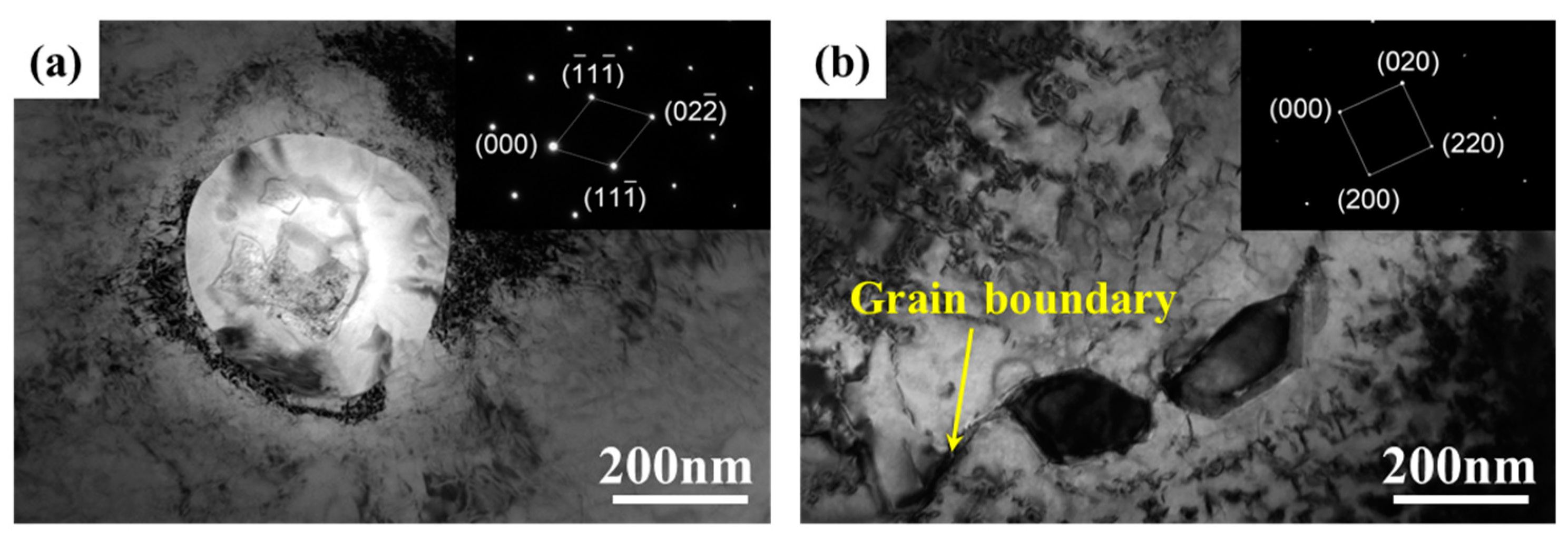
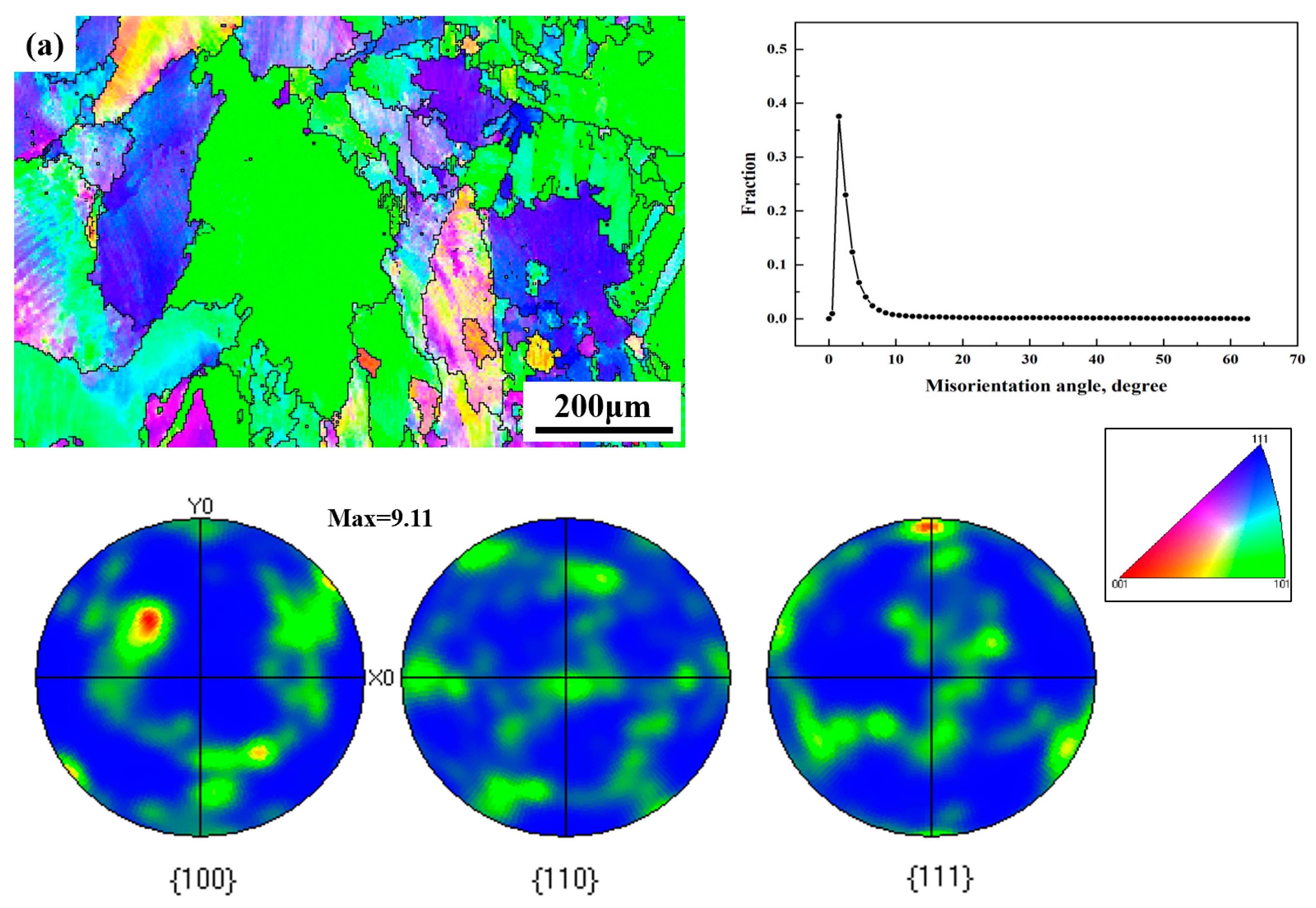
The Inconel 625 deposited metal consists of matrix γ, Laves phase, as well as elliptical MC-type carbides. After heat treatment, the chain-like Laves phase fractures and dissolves, and a large amount of MC-type carbides are precipitated in the grain boundary. M23C6-type carbides appear at the grain boundaries, and the size of the carbides inside the grain is significantly larger than of those at the grain boundaries. The grains of the SA sample became finer, and a large number of tiny particles of the γ″ phase precipitated, which improved the strength of the metal. Moreover, the SA sample has a strong <100> solidification texture, and the maximum texture strength is much higher than that of the AW sample.
(2)
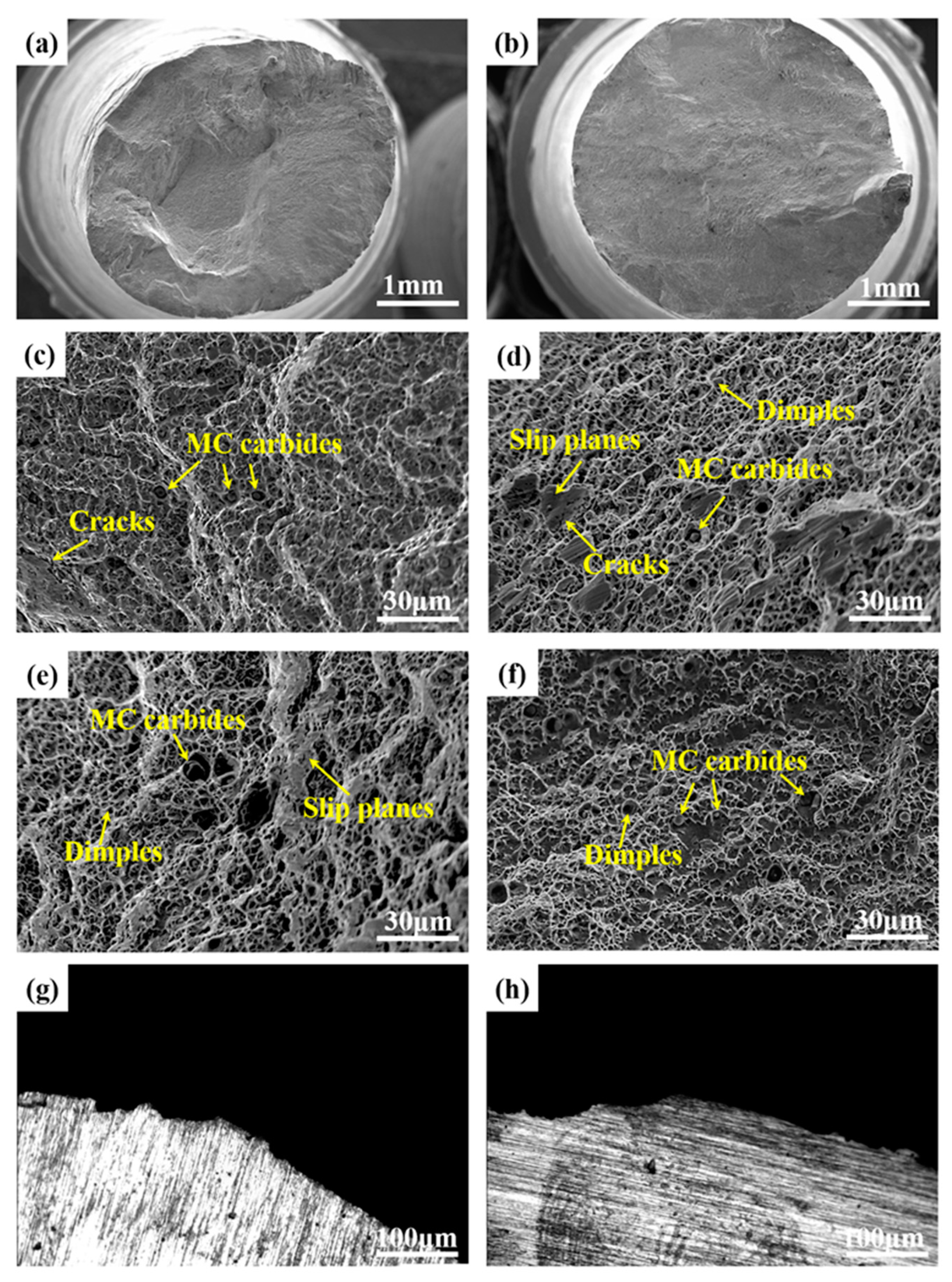
The morphology and quantity of precipitates in tensile fractures under different states vary depending on the sample. The fracture mechanism of the sample fracture is a mixed type, with many ductile dimples and precipitated phases at the fracture surface. Compared with the fracture morphology of the welded overlay layer, the dimples in the alloy fracture after heat treatment became shallower, and the plasticity of the overlay layer decreased. The brittle fracture and crack zone are attributed to intergranular M23C6 carbides and the γ″ phase.
(3)
The tensile strength and yield strength of the as-welded Inconel 625 deposited metal were 525.45 MPa and 373.04 MPa, respectively, and the elongation was 29.81%. After solution and aging treatment, the yield strength increased to 525.45 MPa and the elongation decreased. After solution and aging heat treatment, the Inconel 625 deposited metal exhibits a significant work-hardening effect when stretched at 600 °C. The formation of the γ″ phase greatly improved the strength of Inconel 625 but decreased the elongation. The primary deformation mechanism of the as-welded Inconel 625 deposited metal during stretching at 600 °C is the accumulation of many dislocations in the matrix. After the solution and aging treatment, the bypass mechanism of dislocations has been activated, resulting in many continuous stacking faults.

Author Contributions

All authors contributed to the study conception and design. Material preparation, data curation, and analysis, Y.W. and Z.D.; writing—original draft preparation, Y.W.; writing—review and editing, Y.S. All authors have read and agreed to the published version of the manuscript.

Funding

This research received no external funding.

Data Availability Statement

The data presented in this study are available on request from the corresponding author due to privacy.

Acknowledgments

We thank the associate editor and the reviewers for their useful feedback that improved this paper.

Conflicts of Interest

The authors declare no conflicts of interest.

References

  1. Mittra, J.; Dubey, J.S.; Banerjee, S. Acoustic emission technique used for detecting early stages of precipitation during aging of Inconel 625. Scr. Mater. 2003, 49, 1209–1214. [Google Scholar] [CrossRef]
  2. Neal, D.E.; Philip, J.M.; John, P.S.; Yukinori, Y. Microstructure evolution of alloy 625 foil and sheet during creep at 750 °C. Mater. Sci. Eng. A 2008, 498, 412–420. [Google Scholar] [CrossRef]
  3. Mostafaei, A.; Toman, J.; Stevens, E.L.; Hughes, E.T.; Krimer, Y.L.; Chmielus, M. Microstructural evolution and mechanical properties of differently heat-treated binder jet printed samples from gas- and water-atomized alloy 625 powders. Acta Mater. 2017, 124, 280–289. [Google Scholar] [CrossRef]
  4. Rodriguez, R.; Hayes, R.W.; Berbon, P.B.; Lavernia, E.J. Tensile and creep behavior of cryomilled Inco 625. Acta Mater. 2003, 51, 911–929. [Google Scholar] [CrossRef]
  5. Maj, P.; Koralnik, M.; Adamczyk-Cieslak, B.; Romelczyk-Baishya, B.; Kut, S.; Pieja, T.; Mrugala, T.; Mizera, J. Mechanical properties and microstructure of Inconel 625 cylinders used in aerospace industry subjected to flow forming with laser and standard heat treatment. Int. J. Mater. Form. 2018, 12, 135–144. [Google Scholar] [CrossRef]
  6. Cooper, D.E.; Blundell, N.; Maggs, S.; Gibbons, G.J. Additive layer manufacture of Inconel 625 metal matrix composites. reinforcement material evaluation. J. Mater. Process. Technol. 2013, 213, 2191–2200. [Google Scholar] [CrossRef]
  7. Aslam, M.; Sahoo, C.K. Development of hard and wear-resistant SiC-AISI304 stainless steel clad layer on low carbon steel by GMAW process. Mater. Today Commun. 2023, 36, 106444. [Google Scholar] [CrossRef]
  8. Zhang, X.; Li, Z.; Gao, H. Online measurement of droplet size by actively exciting droplet oscillation in GMAW and GMAW-AM. J. Manuf. Process. 2023, 85, 1144–1153. [Google Scholar] [CrossRef]
  9. Shukla, P.; Chitral, S.; Kumar, T.; Kiran, D.V. The influence of GMAW correction parameters on stabilizing the deposition characteristics for wire arc additive manufacturing. J. Manuf. Process. 2023, 90, 54–68. [Google Scholar] [CrossRef]
  10. Wu, K.; Cao, X.; Yin, T.; Zeng, M.; Liang, Z. Metal transfer process and properties of double-wire double pulsed gas metal arc welding. J. Manuf. Process. 2019, 44, 367–375. [Google Scholar] [CrossRef]
  11. Jang, C.; Lee, J.; Kim, J.S.; Jin, T.E. Mechanical property variation within Inconel 82/182 dissimilar metal weld between low alloy steel and 316 stainless steel. Int. J. Press. Vessel. Pip. 2008, 85, 635–646. [Google Scholar] [CrossRef]
  12. Kumar, N.P.; Shanmugam, N.S.; Sreedhar, G. High cycle fatigue behaviour of Inconel 625 weld overlay on AISI 316L plate. Surf. Coat. Technol. 2021, 415, 127138. [Google Scholar] [CrossRef]
  13. Lee, J.; Terner, M.; Jun, S.; Hong, H.-U.; Copin, E.; Lours, P. Heat treatments design for superior high-temperature tensile properties of Alloy 625 produced by selective laser melting. Mater. Sci. Eng. A 2020, 790, 139720. [Google Scholar] [CrossRef]
  14. Marchese, G.; Parizia, S.; Rashidi, M.; Saboori, A.; Manfredi, D.; Ugues, D.; Lombardi, M.; Hryha, E.; Biamino, S. The role of texturing and microstructure evolution on the tensile behavior of heat-treated Inconel 625 produced via laser powder bed fusion. Mater. Sci. Eng. A 2020, 769, 138500. [Google Scholar] [CrossRef]
  15. Xing, X.; Di, X.; Wang, B. The effect of post-weld heat treatment temperature on the microstructure of Inconel 625 deposited metal. J. Alloys Compd. 2014, 593, 110–116. [Google Scholar] [CrossRef]
  16. Lass, E.A.; Stoudt, M.R.; Katz, M.B.; Williams, M.E. Precipitation and dissolution of δ and γ′′ during heat treatment of a laser powder-bed fusion produced Ni-based superalloy. Scr. Mater. 2018, 154, 83–86. [Google Scholar] [CrossRef]
  17. Hu, Y.; Lin, X.; Zhang, S.; Jiang, Y.; Lu, X.; Yang, H.; Huang, W. Effect of solution heat treatment on the microstructure and mechanical properties of Inconel 625 superalloy fabricated by laser solid forming. J. Alloys Compd. 2018, 767, 330–344. [Google Scholar] [CrossRef]
  18. Terner, M.; Lee, J.; Marchese, G.; Biamino, S.; Hong, H.-U. Electron Backscattered Diffraction to Estimate Residual Stress Levels of a Superalloy Produced by Laser Powder Bed Fusion and Subsequent Heat Treatments. Materials 2020, 13, 4643. [Google Scholar] [CrossRef] [PubMed]
  19. Hu, Y.; Lin, X.; Li, Y.; Zhang, S.; Zhang, Q.; Chen, W.; Li, W.; Huang, W. Influence of heat treatments on the microstructure and mechanical properties of Inconel 625 fabricated by directed energy deposition. Mater. Sci. Eng. A 2021, 817, 141309. [Google Scholar] [CrossRef]
  20. Dinda, G.P.; Dasgupta, A.K.; Mazumder, J. Laser aided direct metal deposition of Inconel 625 superalloy: Microstructural evolution and thermal stability. Mater. Sci. Eng. A 2009, 509, 98–104. [Google Scholar] [CrossRef]
  21. Marchese, G.; Lorusso, M.; Parizia, S.; Bassini, E.; Lee, J.-W.; Calignano, F.; Manfredi, D.; Terner, M.; Hong, H.-U.; Ugues, D.; et al. Influence of heat treatments on microstructure evolution and mechanical properties of Inconel 625 processed by laser powder bed fusion. Mater. Sci. Eng. A 2018, 729, 64–75. [Google Scholar] [CrossRef]
  22. Safarzade, A.; Sharifitabar, M.; Afarani, M.S. Effects of heat treatment on microstructure and mechanical properties of Inconel 625 alloy fabricated by wire arc additive manufacturing process. Trans. Nonferrous Met. Soc. China 2020, 30, 3016–3030. [Google Scholar] [CrossRef]
  23. Hu, Y.; Li, Y.; Zhang, S.; Lin, X.; Wang, Z.; Huang, W. Effect of solution temperature on static recrystallization and ductility of Inconel 625 superalloy fabricated by directed energy deposition. Mater. Sci. Eng. A 2020, 772, 138711. [Google Scholar] [CrossRef]
  24. Mostafaei, A.; Behnamian, Y.; Krimer, Y.L.; Stevens, E.L.; Luo, J.L.; Chmielus, M. Effect of solutionizing and aging on the microstructure and mechanical properties of powder bed binder jet printed nickel-based superalloy 625. Mater. Des. 2016, 111, 482–491. [Google Scholar] [CrossRef]
  25. Özgün, Ö.; Gülsoy, H.; Findik, F. The effect of aging treatment on the fracture toughness and impact strength of injection molded Ni-625 superalloy parts. Mater. Charact. 2015, 108, 8–15. [Google Scholar] [CrossRef]
  26. Li, C.; White, R.; Fang, X.Y.; Weaver, M.; Guo, Y.B. Microstructure Evolution Characteristics of Inconel 625 Alloy from Selective Laser Melting to Heat Treatment. Mater. Sci. Eng. A 2017, 705, 20–31. [Google Scholar] [CrossRef]
  27. Yu, J.; Lian, Z.; Chu, Z.; Sun, X.; Guan, H.; Hu, Z. Properties and microstructures of M951 alloy after long-term exposure. Mater. Sci. Eng. A 2010, 527, 1896–1902. [Google Scholar] [CrossRef]
  28. Kreitcberga, A.; Brailovskia, V.; Turenneb, S. Effect of heat treatment and hot isostatic pressing on the microstruc ture and mechanical properties of Inconel 625 alloy processed by laser powder bed fusion. Mater. Sci. Eng. A 2017, 689, 1–10. [Google Scholar] [CrossRef]
  29. Robin, M.; Forbes, J.; Laurence, A.J. The structural evolution of superalloy ingots during hot working. JOM 1999, 51, 27–31. [Google Scholar] [CrossRef]
  30. Chu, Z.; Yu, J.; Sun, X.; Guan, H.; Hu, Z. High-Temperature Creep Deformation and Fracture Behavior of a Directionally Solidified Ni-Base Superalloy DZ95. Metal. Mater. Trans. A 2009, 40, 2927–2937. [Google Scholar] [CrossRef]
  31. Long, H.; Mao, S.; Liu, Y.; Zhang, Z.; Han, X. Microstructural and compositional design of Ni-based single crystalline superalloys-A review. J. Alloys Compd. 2018, 743, 203–220. [Google Scholar] [CrossRef]
  32. Ro, Y.; Koizumi, Y.; Harada, H. High temperature tensile properties of a series of nickel-base superalloys on a γ/γ′ tie line. Mater. Sci. Eng. A 1997, 223, 59–63. [Google Scholar] [CrossRef]
  33. Huang, K.-T.; Lui, T.-S.; Chen, L.-H. Effect of Dynamically Recrystallized Grain Size on the Tensile Properties and Vibration Fracture Resistance of Friction Stirred 5052 Alloy. Mater. Trans. 2006, 47, 2405–2412. [Google Scholar] [CrossRef]
  34. Popovich, V.A.; Borisov, E.V.; Popovich, A.A.; Sufiiarov, V.S.; Masaylo, D.V.; Alzina, L. Functionally graded Inconel 718 processed by additive manufacturing: Crysta-llographic texture, anisotropy of microstructure and mechanical properties. Mater. Des. 2017, 114, 441–449. [Google Scholar] [CrossRef]
  35. Mittra, J.; Banerjee, S.; Tewari, R.; Dey, G.K. Fracture behavior of Alloy 625 with different precipitate microstructures. Mater. Sci. Eng. A 2013, 574, 86–93. [Google Scholar] [CrossRef]
  36. Liu, X.; Fan, J.; Zhang, P.; Cao, K.; Wang, Z.; Chen, F.; Liu, D.; Tang, B.; Kou, H.; Li, J. Influence of heat treatment on Inconel 625 superalloy sheet: Carbides, γ″, δ phase precipitation and tensile deformation behavior. J. Alloys Compd. 2023, 930, 167522. [Google Scholar] [CrossRef]
  37. Décamps, B.; Morton, A.J.; Condat, M. On the mechanism of shear of γ′ precipitates by single (a/2) ⟨110⟩ dissociated matrix dislocations in Ni-based superalloys. Philos. Mag. A 1991, 64, 641–668. [Google Scholar] [CrossRef]
Figure 1. Schematics of deposition path (unit: mm).
Crystals 14 00764 g001
Figure 2. The schematic of the tensile sample (unit: mm) and physical picture.
Crystals 14 00764 g002
Figure 3. DSC curve of Inconel 625 deposited metal sample.
Crystals 14 00764 g003
Figure 4. Effect of different solid solution methods on tensile properties. (a) Different solution temperatures; (b) different solution time at the same temperature (1140 °C).
Crystals 14 00764 g004
Figure 5. X-ray diffraction of longitudinal section on fracture surface of Inconel 625 deposited metal. (a) AW sample, (b) SA sample.
Crystals 14 00764 g005
Figure 6. SEM morphology of the Inconel 625 deposited metal at 600 °C. (a) AW sample, (b) SA sample.
Crystals 14 00764 g006
Figure 7. TEM field photos of Figure 6 and the diffraction spots in the selected area. (a) AW sample, (b) SA sample.
Crystals 14 00764 g007
Figure 8. IPF mapping and PF mapping of an (a) AW sample and a (b) SA sample.
Crystals 14 00764 g008aCrystals 14 00764 g008b
Figure 9. Engineering stress–strain curves at 600 °C.
Crystals 14 00764 g009
Figure 10. SEM–SE images (af) and OM maps (g,h) showing rupture surface for tensile tests at 600 °C. (a), (c), (e), (g) AW sample and (b), (d), (f), (h) SA sample, respectively.
Crystals 14 00764 g010
Figure 11. TEM images showing deformation microstructures at 600 °C. (a) AW sample and (b) SA sample.
Crystals 14 00764 g011
Table 1. Energy spectrum analysis of precipitates in GMAW Inconel 625 at 600 °C (atomic fraction, %).
PositionNiCrFeNbMoTiC
A64.5024.592.842.974.230.720.15
B40.5520.137.2617.3113.840.790.12
C32.9212.652.4318.3113.720.6919.28
D64.5024.592.842.974.230.720.15
Table 2. Mechanical properties of Inconel 625 alloy at 600 °C.
SampleYield Strength
(σb/MPa)
Tensile Strength
(σs/MPa)
Elongation
(EL)
Shrinkage of Section
(R/A)
Strain Hardening Index
(n)
AW373.04535.5429.81%19.6%0.37
SA525.45709.0126.93%16.1%0.42
Disclaimer/Publisher’s Note: The statements, opinions and data contained in all publications are solely those of the individual author(s) and contributor(s) and not of MDPI and/or the editor(s). MDPI and/or the editor(s) disclaim responsibility for any injury to people or property resulting from any ideas, methods, instructions or products referred to in the content.

