Review

A Review of Deep-Red (650–700 nm)-Emitting Semiconductor Nanocrystals

by
Geyu Jin
1,
Fangze Liu
2,
Jing Wei
1 and
Hongbo Li
1,*
1
School of Materials Science and Engineering, Beijing Institute of Technology, Beijing 100081, China
2
Advanced Research Institute of Multidisciplinary Sciences, Beijing Institute of Technology, Zhuhai 519088, China
*
Author to whom correspondence should be addressed.
Crystals 2024, 14(9), 788; https://doi.org/10.3390/cryst14090788
Submission received: 15 August 2024 / Revised: 27 August 2024 / Accepted: 3 September 2024 / Published: 5 September 2024
(This article belongs to the Special Issue Advances of Perovskite Solar Cells—2nd Edition)

Abstract

:
Deep-red light has significant application value in various fields, including biomedicine, plant cultivation, and displays. The development of high-efficiency deep-red luminescent materials is therefore of great importance. Semiconductor nanocrystals have been extensively studied as novel luminescent materials due to their wavelength tunability, narrow emission linewidth, and high luminescence efficiency. However, the advancement of deep-red nanocrystals has lagged behind that of red, green, and blue nanocrystals, primarily due to material selection limitations. This review summarizes the recent progress in the synthesis of deep-red nanocrystals based on their material composition, including II-VI, III-V, I-III-VI, and perovskite nanocrystals.

1. Introduction

Deep-red light with a wavelength between 650 nm and 700 nm is a special range of the visible spectrum owing to its high penetrability and bio-friendly features. Its applications span fields including clinical treatment [1,2], enhancement of plant growth [3,4], development of white light sources with elevated color rendering effects [5,6,7], and provision of a wide color gamut for displays [8].
Semiconductor nanocrystals (NCs) or quantum dots (QDs) are highly luminescent materials due to their quantum confinement effect. Compared with conventional organic light-emitting materials, QDs have the advantages of easily tunable wavelength, narrow emission linewidth, and high chemical stability [9,10]. The emitting wavelength of QDs can be tuned by changing their size or chemical composition, constructing heterostructures to control the band alignment between the core and the shell, or introducing impurities to generate mid-band -gap energy levels. Reducing defects to increase the radiative recombination rate is critical to improving the photoluminescence quantum yield (PLQY) of QDs. Internal defects can be reduced by regulating the growth process of QDs, while surface defects can be passivated by organic ligands or inorganic shell coatings [11,12]. Currently, red, green, and blue QDs used as light-emitting layer materials for light-emitting diodes (QLEDs) have achieved external quantum efficiency (EQE) and lifetimes close to commercial standards [13,14,15]. However, due to limited material selection, deep-red QDs still fall short of other visible light QDs in terms of stability, luminous intensity, and color purity.
Deep-red QDs can be realized using II-VI, III-V, or I-III-VI semiconductors as well as metal halide perovskites. However, these materials face different challenges to achieve high PLQY in the deep-red region. For example, to achieve deep-red emission, the sizes of CdSe and InP QDs need to be excessively large, which inevitably induces high defect density and severely deteriorates the PLQY [16,17]. Although deep-red perovskite QDs have shown high PLQY, their inherent instability limits further applications [18,19]. Compared with traditional isotropic QDs, anisotropic NCs, such as nanorods (NRs) and nanoplates (NPLs), have received much attention in recent years for their unique polarized emission, which can improve the photon out-coupling efficiency and break the theoretical EQE limit of isotropic QDs. Limited by their growth mechanism, anisotropic NCs are mainly composed of II-VI semiconductors. These NCs exhibit strong quantum confinement effects in the radial (NRs) or thickness direction (NPLs), as well as narrow emission linewidths, large Stokes shifts, and unique polarized emissions, which make them ideal light-emitting layers in LEDs [20,21,22].
This review summarizes the recent progress in the design and synthesis of deep-red NCs, including II-VI QDs, II-VI NRs, II-VI NPLs, III-V QDs I-III-VI QDs, and perovskite QDs. We compare their optical properties, such as PL peak position, full width at half maxima (FWHM), and PLQY, and summarize their synthesis methods, optimization processes, and potential applications.

2. Different Types of Deep-Red Nanocrystals

2.1. II-VI Nanocrystals

CdSe QDs are the most studied II-VI semiconductors, and green and red CdSe QDs have achieved superior optical properties. However, due to the relatively large bulk band gap, CdSe QDs need to grow larger than 7 nm to reach PL peaks above 650 nm [23,24], which makes it difficult to maintain a high PLQY because of the decrease in radiative recombination rates due to the increased defect density with increasing size. Recently, Liu et al. achieved the current best PLQY for CdZnSe-based QDs with a large size of 13 nm. The addition of Zn avoids a significant decrease in PLQY during the increase in quantum dot size, but the PL peak position is still limited to 650 nm [16]. To further red-shift the PL emission, adding Te to CdS and CdSe to form alloyed QDs is an effective route. Owing to the optical bending effects, alloyed CdSeTe and CdSTe QDs exhibit lower emission energies than CdSe and CdS QDs with the same size, respectively [25,26,27,28,29,30]. Emission redshift can also be achieved by constructing type II core–shell structures that allow carriers to delocalize to the shell layer, thus reducing the photon energy. The enhancement of PLQY and stability can be achieved through the construction of complex core–shell structures, especially those with alloyed shell and multi-shell structures.
II-VI NPLs are also discussed in this section. Influenced by the strong exciton confinement in the thickness direction, the effect of heterostructures on the emission energy of NPLs is significant. Compared with CdSe QDs, it is easier to achieve deep-red emission with CdSe NPLs by constructing core–shell or core–crown heterostructures.
Representative deep-red II-VI NCs are listed in Table 1.
Bailey et al. reported the optical bending effect on the luminescence of CdSeTe alloyed QDs. As shown in Figure 1, the band gap and luminescence wavelength of CdSeTe QDs are regulated by both size and composition, and there is an obvious nonlinear relationship between Te content and the band gap energy (Figure 1b) or luminescence wavelength (Figure 1c). This optical bending effect is caused by the difference in atomic size and electronegativity values of different ions. As a result, the band gap of CdSeTe QDs gradually decreases as the Te content increases from 0% to 60%, where the band gap reaches the minimum value, and higher Te content tends to increase the band gap [25]. Jiang et al. achieved CdSeTe QDs with emissions tuned in the range of 480–850 nm by adjusting the ratio of Se to Te and controlling the reaction temperature. The higher reactivity of Te compared to Se resulted in the formation of a gradient structure consisting of a high Te ratio in the core and a high Se ratio on the surface of the QDs, which made the structure more resistant to oxidation compared to pure CdTe QDs. However, degradation still occurred after prolonged storage of 1 day, resulting in a blueshift of luminescence and a decrease in PLQY [28]. Therefore, the authors applied a one-monolayer-thick CdS shell coating at 280 °C to further improve the stability [26].
The shell coating of CdSeTe QDs was further studied by Pons et al. The CdSeTe/CdZnS QDs were obtained by dropwise addition of S/Zn precursor to a trioctylamine solution containing CdSeTe QDs and Cd precursor, and the thickness of the shell layer could reach up to 3 monolayers. The thick shell successfully avoided PL quenching during the transfer from the organic phase to the aqueous phase, enabling further application in the field of bioimaging probes [30]. Similarly, Liang et al. investigated the synthesis of CdSeTe/ZnS QDs in aqueous solution to avoid the reduction of PLQY during phase transfer. The authors pointed out that low temperature is important to avoid core ripening and achieve uniform ZnS encapsulation. The PLQY of the core–shell QDs reached 68% in the deep-red region, and the optical properties remained stable for several months [31].
CdSTe QDs are similar to CdSeTe QDs in terms of emission wavelength tuning. Gurusinghe et al. obtained homogeneously alloyed CdSTe QDs in the range of 690–745 nm and gradient-alloyed CdSTe QDs in the range of 670–695 by controlling the ratio of injected S to Te precursors [29]. The optical bending effect of the gradient-alloyed QDs was less pronounced than that of the homogeneous alloy, leading to a smaller PL redshift, which was consistent with the previous observations in CdSeTe QDs.
Kunstman et al. obtained CdTeS/ZnS QDs by one-pot aqueous phase synthesis. Briefly, NaHTe was rapidly injected into an aqueous solution containing CdCl2, Zn(OAc)2, and 3-mercaptopropionic acid (MPA) in an alkaline environment. S ions were supplied by thermally decomposed MPA. Due to the lower reactivity of Zn than Cd, Te and S preferentially reacted with Cd to form CdTeS QDs. After the Cd precursor was depleted, the remaining S and Zn started to form a ZnS shell layer. The size of the CdTeS core was adjusted by the ratio of precursors, and the PL peaks covered a wide range from green to near-infrared with a PLQY of 35% [32]. Recently, Loghina et al. developed disubstituted thiourea as a new source of S to achieve the synthesis of CdTeS/CdxZn1−xS QDs in the organic phase. The Cd passivated defects in the shell layer, and the QDs with high Cd content exhibited a higher PLQY than those with a low Cd content [33].
Type II core–shell structures can achieve a wide wavelength range by allowing the delocalization of carriers to the shell layer. Smith et al. investigated the change in the energy band structure of CdTe/ZnSe QDs during the deposition of ZnSe shell on CdTe cores. They found that at the nanoscale, due to compression of the core by the ZnSe shell, the CdTe conduction band energy increased while the ZnSe valence band energy decreased, and thus the band alignment changed from type I to type II (Figure 2). In addition, smaller cores were more susceptible to shell layer compression, resulting in a more significant of redshift than in the larger cores. By modifying the core size and shell layer thickness, the emission wavelength of CdTe/ZnSe QDs covered a wide range of 500–1050 nm [34].
Similar modifications of band alignment also exist in other typical type II heterostructures, such as CdTe/CdS and CdTe/CdSe. In the synthesis of CdTe/CdS QDs, Dai et al. obtained small CdTe cores with a diameter of less than 3 nm by limiting the amount of Te precursor, which led to a larger redshift after the shell coating. The PL peak was gradually redshifted from 600 nm to 815 nm with the increased shell coating time [36]. Mehriban et al. obtained CdTe/CdS/ZnS QDs by directly injecting Zn precursors into a crude solution of CdTe/CdS QDs. For CdTe/CdS QDs with emission in the range of 650–660 nm, the PL peak position of the QDs showed a slight redshift and the PLQY was enhanced from 57% to 64% after growing a thin layer of ZnS shell [38].
Chin et al. achieved epitaxial growth of CdSe on CdTe QDs via a successive ionic layer adsorption and reaction (SILAR) method at a low temperature of 150 °C. Low-activity shell precursors were alternatively added in drops to avoid homogeneous nucleation of CdSe QDs and CdTe core ripening [51]. For the synthesis of CdTe/CdSe/ZnS, Zhang et al. referred to the method introduced in [51]. The CdSe branched growth was avoided by replacing trioctylphosphine oxide (TOPO) with the non-coordinating solvent 1-octadecene (ODE) [34]. The slow epitaxial growth of CdSe efficiently passivated surface defects, and the obtained CdTe/CdSe QDs reached a peak PLQY in the deep-red band of >90% with a FWHM of 30–40 nm. For the epitaxial growth of the ZnS layer, the authors found that the single precursor Zn(DDTC)2 was more suitable compared to the mixture of zinc carboxylate and sulfur, as it can thermally decompose at lower temperatures to release Zn and S ions. The QDs after encapsulating ZnS achieved high stability for effective exciton confinement inside the shell and remained stable for several days even after transfer to aqueous solvent (Figure 3) [39]. For deep-red QLEDs, Shen et al. fabricated CdTe/CdSe-based QLEDs with a maximum EQE of 6.19% at a peak wavelength of 689 nm [40].
The most commonly developed NRs are CdSe/CdS “dot-in-rod” NRs. Moreels et al. attempted to achieve PL redshift by increasing the size of the CdSe core or the thickness of the shell; however, the maximum emission wavelength was limited to 650 nm (Figure 4) [45]. By contrast, doping the CdSe core with a small amount of Te could achieve the deep-red emission of NRs. However, similar to QDs, Te doping in NRs also causes broadened PL and decreased PLQY. Although the optical properties can be optimized by shell layer design, the performance of deep-red NRs still falls behind of that of undoped red-emitting NRs [46,52]. Therefore, further development and optimization of deep-red NRs are required.
For NPLs, constructing heterostructures is a better way to achieve deep-red emission than doping, which usually causes loss of optical properties [53,54,55]. The emission wavelength of core–shell NPLs is determined by the thicknesses and the shell composition. Rossinelli et al. coated the CdSe NPLs with a fourteen-monolayer-thick CdS shell, which shifted the PL peak position from 515 nm to 670 nm. The uniform shell ensured a narrow PL FWHM of 20 nm and a PLQY of 50–60% [47]. In another report, the authors investigated different shell compositions and compared the effect of CdSe core thickness on the optical properties. By increasing the thickness of CdSe core and constructing an alloyed CdZnS shell, the NPLs exhibited a high PLQY of 92% at 692 nm [48].
LEDs based on deep-red NPLs were demonstrated by Shabani et al. using a complex NPL heterostructure of (CdSe/CdS)@(CdS/CdZnS). The CdS crown was first grown around the CdSe NPLs to form a core–crown structure, which was further coated with CdS and CdZnS shells that covered all crystalline faces. The PL peak redshifted from 512 nm to 665 nm after CdS and CdZnS shell coating (Figure 5). The deep-red LEDs based on these NPLs had an EQE of up to 9.89% due to the good carrier confinement by the multi-shell structure [49]. In a subsequent report, the authors increased the thickness of the CdS shell and the PL peak of (CdSe/CdS)@(4CdS/CdZnS) NPLs further redshifted to 700 nm [50].

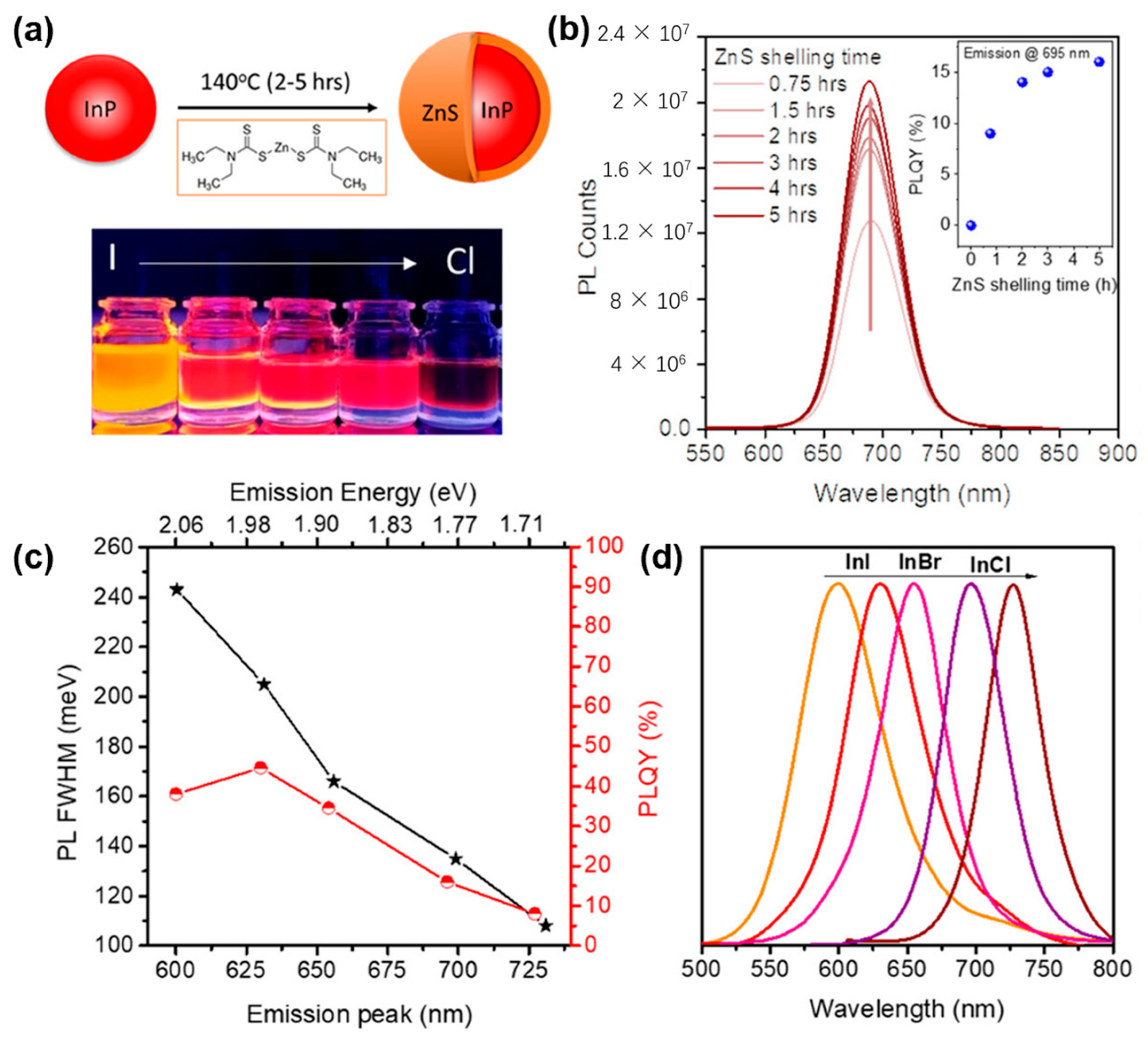
2.2. III-V Nanocrystals

InP is a widely studied III-V semiconductor with a bulk band gap of 1.35 eV. InP QDs cover a wide spectral range from visible to near-infrared. They are considered as an environment-friendly substitute for II-VI group QDs containing heavy metals and have been applied in many fields, such as displays and imaging [56,57,58].
In early studies, silylphosphine was commonly used as the phosphorus source in the synthesis of InP, while the low dissociation energy of the P–-Si bond led to the rapid release of phosphorus, which deviated the nucleation growth process from the classical LaMer model. The rapid depletion of precursors also led to the maturation of QDs, which made it difficult to obtain high-quality large-size QDs [59,60,61,62]. Therefore, using low reactive precursors to synthesize large InP QDs has been proven to achieve deep-red emission [63,64].
Due to the weak bonding of organic ligands, a large number of In and P dangling bonds exist on the surface of InP QDs, which create mid-gap energy levels in QDs to trap carriers, leading to a decrease in PLQY [65,66]. Shell coating is an effective method to passivate defects. However, the large lattice mismatch between InP and ZnS (7.6%) makes it difficult to grow a thick ZnS shell, which becomes more significant when the core size is larger. Choosing materials with a better lattice match, such as ZnSe, or alloyed materials can achieve a more uniform shell coating, thereby optimizing the luminescence performance of InP QDs. Constructing different types of core–shell structures can also help to achieve PL redshift. For example, shells of medium-band gap materials allow electrons to delocalize easily from the core to the shell, thereby achieving redshifted emission to the deep-red region.
The properties and synthesis methods of deep-red InP QDs are summarized in Table 2.
In 1996, Micic et al. synthesized InP QDs with diameters between 2.6 nm and 6 nm using indium oxalate and tris(trimethylsilyl)phosphine precursors, and for the first time, obtained single-peak band-edge emission by eliminating defect peaks through HF passivation. However, the FWHM of these QDs was very broad, especially at larger QD sizes, reaching 70 nm [61].
In order to narrow the emission bandwidth, Yang et al. developed a new synthesis scheme for full-spectrum luminescent InP/ZnS QDs. Indium acetate and tris(trimethylsilyl)phosphine as precursors were first premixed sufficiently at room temperature to form the initial fine InP nuclei. The growth rate of the QDs was controlled by the addition of zinc stearate in the subsequent heated growth process. Although this approach achieved QDs covering 430–670 nm luminescence and the FWHM at 550 nm decreased to below 50 nm, the FWHM of QDs in the deep-red region increased significantly to above 80 nm as the zinc stearate was gradually consumed [80].
Given that silylphosphine is not an ideal precursor for the synthesis of large InP QDs, in order to control the growth process, ammonia-phosphorus with a higher P–-N bond energy was studied. The emission wavelength was controlled by modifying the type of InX2 (X = Cl, Br, I) and the In:P ratio to modulate the precursor conversion rate. However, ZnCl2, a passivator commonly used in the synthesis of InP QDs using ammonia phosphorus, has been found to lead to shallow trap states in QDs, resulting in broadened PL width [81]. Recently, Reiss et al. synthesized InP QDs with tunable PL between 507 nm and 728 nm using In(I)X (X = Cl, Br, I) as the indium source (Figure 6). In addition to providing In ions, the monovalent indium also acted as a reducing agent in the disproportionation reaction of aminophosphine, which overcame the limitation of the In/P ratio in the traditional scheme using InX2 and achieved a wider wavelength range. Without adding ZnCl2, the PL FWHM of InP QDs was only 43 nm at 670 nm, which is the narrowest value for deep-red InP QDs so far. However, due to the large lattice mismatch between InP and ZnS, shell growth was challenging and the PLQY of InP/ZnS QDs in this study was only 16%, which is considerably lower than that of red-emitting InP QDs [69].
In order to reduce the interfacial strain and defects, introducing an intermediate shell with small lattice mismatches can further improve the optical performance of InP core/shell QDs. This has been well demonstrated in green- and red-emitting InP QDs, which achieve close to 100% PLQY [82,83]. Huang et al. successfully synthesized multi-shell InP/ZnSe/ZnSeS/ZnS QDs with a PL peak located at 680 nm. A low-reactivity indium precursor was introduced to synthesize large InP cores with a PL peak at 650 nm. The coating of a ZnSe layer that allowed electron delocalization resulted in red-shifted emission to 683 nm. A ZnSeS shell was added as a transition layer prior to the ZnS shell, which provided a smoother potential barrier and reduced interfacial defects compared to direct growth of the ZnS shell. The PLQY of the final QDs reached 95%, which is the highest value available for deep-red InP QDs [72]. However, the PL FWHM was broadened to 66 nm during the ZnSeS coating. In a subsequent report, Soheyli et al. were able to narrow the PL FWHM of InP/ZnSe/ZnS QDs to 50 nm, which came at the cost of a lower PLQY of 60% [73]. Recently, Reiss et al. applied a different multilayer shell coating to InP QDs, and the resulting InP/ZnSe/ZnS/Al2O3 QDs emitting at 725 nm had an FWHM of only 45 nm. The Al2O3 layer not only played the same role as ZnS to confine carriers and improve the PLQY but also resulted in significantly improved stability of the QDs during transfer to the aqueous phase via ligand exchange, which extended their application in biomedical fields [74].
In addition to optimizing the synthesis of large InP QDs, other methods used to red-shift the luminescence peak position include the construction of anti-I-type core–shell structures and doping. However, InP QDs synthesized by these methods at present usually have a wide half-peak width [75,77,78,79,84].

2.3. I-III-VI Nanocrystals

I-III-VI QDs such as CuInS2 and AgInS2 can easily achieve deep-red emission by composition and size modulation. However, limited by the luminescence mechanism of multiple radiation centers associated with defects states, the FWHM is usually over 100 nm. The poor color purity of I-III-VI QDs renders them unsuitable for color displays. However, the broad emission bandwidth and substantial Stokes shift indicate their potential application for white light LEDs [85,86]. The low toxicity of these QDs is highly desired for biomedical imaging, while their long fluorescence lifetimes also make them well suited for fluorescence probes [87,88,89,90,91].
The properties and synthesis methods of I-III-VI deep-red QDs are summarized in Table 3.
As ternary nanocrystals, one of the keys to the synthesis of I-III-VI QDs is to regulate the activity of different metal precursors in binding to sulfur or selenide, which is important for reducing the formation of impurities and defects. In 2004, Castro et al. synthesized CuInS2 QDs for the first time using thermal decomposition of a single-source precursor. Limited by the fixed ionic ratio and activity of the single precursor, the resulting QDs exhibited a limited emission range and extremely low PLQY [92]. In the following report by Peng et al., CuInS2 QDs synthesized using independently regulated precursors exhibited a broader emission range, with a PLQY of 30% after in situ ZnS shelling. As shown in Figure 7, the band edge of CuInS2 QDs with different sizes covered 600–900 nm After size-selective precipitation progress, the photoluminescence excitation (PLE) spectra of CuInS2/ZnS QDs was in good agreement with the excitonic absorption peak, which confirmed that the broadening of PL emission was not from size dispersion [102].
The addition of Zn2+, Sn2+, Ga2+, and other ions during the synthesis of I-III-V QDs can result in the formation of doped or alloyed quaternary QDs, which exhibit enhanced luminescence performance due to the reduction of cationic vacancies and surface defects [94,96,98,101,103,104,105,106,107]. The Cu-In-Zn-S QDs synthesized by Zhang et al. covered the emission range from green to near-infrared by adjusting the elemental composition and size. For example, the PL peak was about 700 nm at a Cu/Zn ratio of 1:1 and gradually blue-shifted with increasing content of Zn, while the PLQY also rose because of the reduction of internal defects, reaching 81% at 630 nm [93]. Xie et al. achieved tunable deep-red and near-infrared emission by the addition of Sn in CuInS2/ZnS QDs. Sn doping decreased the band gap, and with the increment of Sn content, the PL peak of Cu-Sn-In-S/ZnS QDs shifted from 628 nm to 785 nm [95].

2.4. Perovskite Nanocrystals

Metal halide perovskite QDs have attracted great interest in recent years due to their excellent optical properties, such as high PLQY, narrow PL FWHM, and fast radiative recombination. In particular, the all-inorganic perovskite CsPbX3 (X = Cl, Br, I) exhibits enhanced stability compared to organic-inorganic perovskites. The emission wavelength of perovskite QDs is usually tuned by controlling their composition. CsPbI3 is representative deep-red perovskite QDs. Compared with the most studied green CsPbBr3 QDs, CsPbI3 QDs have lower stability and luminescence intensity, which can be explained by calculating the Goldschmidt tolerance factor (t) and octahedral factor (μ) of CsPbI3. In addition, the ionic nature of perovskite results in rapid degradation in polar solvents, which significantly limits its applications. Several strategies, including optimizing surface ligands, ion doping, and constructing heterostructures, have been used to suppress the phase transition and improve the performance of CsPbI3 QDs. In this section, we mainly review the optimization methods of CsPbI3 as representative deep-red perovskite QDs.
The properties and synthesis methods of deep-red perovskite QDs are summarized in Table 4.
Protesescu et al. synthesized a series of colloidal CsPbX3 (X = Cl, Br, I) QDs via the hot injection method. By modifying the injection temperature and the halide composition, the PL position could be adjusted across the visible spectrum (410–700 nm) with excellent PLQY and color purity (Figure 8). The authors further pointed out that compared with stable CsPbBr3 and CsPbCl3 QDs, CsPbI3 QDs gradually transformed into a yellow non-luminescent phase (orthorhombic phase) after prolonged storage [108].
OA and OAm ligands may be released from perovskite QDs due to the protonation and deprotonation process, which reduces the stability of perovskite QDs. Therefore, Pan et al. used a bidentate ligand of 2,2′-iminodibenzoic acid (IDA) to passivate CsPbI3 QDs [111]. Compared with OA with only one carboxyl group, IDA with two carboxyl groups has a larger binding energy with the Pb atoms, which better stabilized the perovskite phase of CsPbI3. In addition, the improved ligand binding energy also resulted in a PLQY of up to 95% in the deep-red region.
Improving the Goldschmidt tolerance factor by changing the bond length between ions reduces the [PbI6]4− octahedral distortion and improves the phase stability. Protesescu et al. added FA+ to CsPbI3 QDs and achieved a PLQY of >70% at 685 nm. The stability of FA0.1Cs0.9PbI3 QDs was significantly improved compared to pure CsPbI3 QDs [113]. However, the organic cations still faced issues such as thermal stability in practical applications. Another approach is to partially substitute Pb+ with other smaller metal ions to improve the tolerance factor. Rogach et al. prepared alloyed CsPb1−xZnxI3 QDs via hot injection. As the Zn content increased, the PL peak position blue-shifted from 678 nm to 662 nm due to lattice shrinking and decreasing size. The PLQY of CsPb0.44Zn0.36I3 reached near 100%. The Zn-alloyed structure also reduced the hole injection barrier compared with CsPbI3 in QLEDs, allowing an enhanced EQE of 15.1%. In addition to Zn2+, other small divalent metal ions such as Ni2+, Mn2+, and Sr2+ or heterovalent ions such as Bi3+, Sb3+, Yb3+, etc. can also achieve significant improvements in stabilizing CsPbI3 QDs [117,118,119].
Due to the soft ionic bonding and the lattice mismatch, it is difficult to build core–shell structures on perovskite QDs, and only a few reports mainly focus on the more stable CsPbBr3 QDs [120,121,122,123,124]. Guo et al. prepared CaIx/γ-CsPbI3/CaI2 core–shell QDs. CaIx nanoparticles were first formed in the reaction solution and then used as seeds for heteroepitaxial growth of orthorhombic CsPbI3[125]. This templated growth mode effectively suppressed the octahedral distortion of perovskite and improved the phase stability of CsPbI3. The toluene dispersion could be stored in air for more than three months. In addition, the excess CaI2 particles could form a large band gap shell outside CsPbI3 QDs through adsorption, which further passivated surface defects. The EQE of the QLED reached as high as 25.3% [115].
Recently, Rogach et al. achieved epitaxial growth of the ZnSe shell on the surface of CsPbI3 QDs through in -situ thermal injection. In order to satisfy the growth temperature of ZnSe, CsPbI3 had to be synthesized and stabilized at high temperatures (over 240 °C). This was achieved by the addition of oleylammonium iodide, which was shown to prevent the phase transition of CsPbI3 at high temperatures. The CsPbI3/ZnSe QDs showed deep-red emission with a PLQY of 96% thanks to the passivation and confinement effects of the ZnSe shell, despite the fact that ZnSe failed to form a complete shell on the CsPbI3 core. Due to the reduction of the exposed surface and the fixation of the octahedral structure by the stable interface, CsPbI3/ZnSe showed a slower degradation rate than bare CsPbI3 QDs (Figure 9) [116].
We note that construction of a complete core–shell structure is an important direction for further research on CsPbI3 QDs and is expected to lead to better stability and optical performance. In addition, heavy -metal-free shells such as ZnSe and ZnS can confine the lead inside the shell, thereby reducing the biological toxicity of perovskite QDs and expanding their applications.

3. Conclusions

Deep-red nanocrystals play important roles in fields including biomedicine, plant growth, and displays. Despite receiving relatively less attention in comparison to that of red, green, and blue nanocrystals, some noteworthy reports on deep-red nanocrystals have emerged in recent years. The aim of this review is to provide a summary of the properties and potential applications of deep-red nanocrystals with different compositions and to offer inspiration for subsequent studies.
1. The QLEDs based on deep-red II-VI QDs need further optimization, which is expected to achieved by introducing an alloyed shell layer with gradient barriers or ligand exchange. Anisotropic nanocrystals have shown great potential in electroluminescent devices in recent years, and the highest EQE of a deep-red QLED based on nanocrystals has been achieved with NPLs with a “core–crown–multishell” structure.
2. Perovskite nanocrystals achieve a high PLQY with a narrow emission linewidth in the deep-red region; however, although many efforts have been devoted to realizing their display applications, they still face the stability issue. In addition, Pb-containing perovskites also have the same potential environmental issues as II-VI Cd-based nanocrystals. Accelerating research on lead-free perovskites or coating Pb-based perovskite nanocrystals with heavy -metal-free materials, similar to Cd-based nanocrystals, may provide possible solutions.
3. Research into heavy metal-free deep-red nanocrystals is necessary. InP QDs have the potential to be excellent alternatives to Cd-based QDs, which they have nearly accomplished in red and green light, but their emission intensity and color purity in the deep-red band need to be further optimized to meet commercial standards.

Author Contributions

Conceptualization, G.J., F.L. and J.W.; methodology, G.J., F.L. and J.W.; software, G.J., F.L. and J.W.; validation, G.J., F.L. and J.W.; formal analysis, G.J.; investigation, G.J.; resources, G.J.; data curation, G.J.; writing—original draft preparation, G.J.; writing—review and editing, F.L. and J.W.; visualization, G.J., F.L. and J.W.; supervision, F.L. and J.W.; project administration, F.L., J.W. and H.L.; funding acquisition, H.L. All authors have read and agreed to the published version of the manuscript.

Funding

This work was supported by the National Natural Science Foundation of China (22179009, U22A2072, 22105018, 52372135, 22379017).

Data Availability Statement

No new data were created or analyzed in this study.

Conflicts of Interest

The authors declare no conflict of interest.

References

  1. Shinhmar, H.; Hogg, C.; Neveu, M.; Jeffery, G. Weeklong Improved Colour Contrasts Sensitivity after Single 670 Nm Exposures Associated with Enhanced Mitochondrial Function. Sci. Rep. 2021, 11, 22872. [Google Scholar] [CrossRef]
  2. Silverå Ejneby, M.; Jakešová, M.; Ferrero, J.J.; Migliaccio, L.; Sahalianov, I.; Zhao, Z.; Berggren, M.; Khodagholy, D.; Đerek, V.; Gelinas, J.N.; et al. Chronic Electrical Stimulation of Peripheral Nerves via Deep-Red Light Transduced by an Implanted Organic Photocapacitor. Nat. Biomed. Eng. 2022, 6, 741–753. [Google Scholar] [CrossRef]
  3. Quang, N.V.; Huyen, N.T.; Tu, N.; Trung, D.Q.; Anh, D.D.; Tran, M.T.; Hung, N.D.; Viet, D.X.; Huy, P.T. A High Quantum Efficiency Plant Growth LED by Using a Deep-Red-Emitting α-Al2O3:Cr3+ Phosphor. Dalton Trans. 2021, 50, 12570–12582. [Google Scholar] [CrossRef] [PubMed]
  4. Zhao, Y.; Shi, L.; Han, Y.; Li, H.; Ji, Z.; Zhang, Z. Luminescent Properties of Zn2+-Doped CaAl12O19:Mn4+ Deep-Red Phosphor for Indoor Plant Cultivation. Ceram. Int. 2019, 45, 8265–8270. [Google Scholar] [CrossRef]
  5. Xuan, T.-T.; Liu, J.-Q.; Xie, R.-J.; Li, H.-L.; Sun, Z. Microwave-Assisted Synthesis of CdS/ZnS:Cu Quantum Dots for White Light-Emitting Diodes with High Color Rendition. Chem. Mater. 2015, 27, 1187–1193. [Google Scholar] [CrossRef]
  6. Wang, X.; Yan, X.; Li, W.; Sun, K. Doped Quantum Dots for White-Light-Emitting Diodes Without Reabsorption of Multiphase Phosphors. Adv. Mater. 2012, 24, 2742–2747. [Google Scholar] [CrossRef] [PubMed]
  7. Wang, X.; Feng, X.; Molokeev, M.S.; Zheng, H.; Wang, Q.; Xu, C.; Li, J.-G. Modulation of Bi3+ Luminescence from Broadband Green to Broadband Deep Red in Lu2WO6 by Gd3+ Doping and Its Applications in High Color Rendering Index White LED and Near-Infrared LED. Dalton Trans. 2023, 52, 2619–2630. [Google Scholar] [CrossRef]
  8. Zhu, R.; Luo, Z.; Chen, H.; Dong, Y.; Wu, S.-T. Realizing Rec. 2020 Color Gamut with Quantum Dot Displays. Opt. Express OE 2015, 23, 23680–23693. [Google Scholar] [CrossRef]
  9. Efros, A.L.; Brus, L.E. Nanocrystal Quantum Dots: From Discovery to Modern Development. ACS Nano 2021, 15, 6192–6210. [Google Scholar] [CrossRef]
  10. Sowers, K.L.; Swartz, B.; Krauss, T.D. Chemical Mechanisms of Semiconductor Nanocrystal Synthesis. Chem. Mater. 2013, 25, 1351–1362. [Google Scholar] [CrossRef]
  11. García De Arquer, F.P.; Talapin, D.V.; Klimov, V.I.; Arakawa, Y.; Bayer, M.; Sargent, E.H. Semiconductor Quantum Dots: Technological Progress and Future Challenges. Science 2021, 373, eaaz8541. [Google Scholar] [CrossRef] [PubMed]
  12. Xiao, P.; Zhang, Z.; Ge, J.; Deng, Y.; Chen, X.; Zhang, J.-R.; Deng, Z.; Kambe, Y.; Talapin, D.V.; Wang, Y. Surface Passivation of Intensely Luminescent All-Inorganic Nanocrystals and Their Direct Optical Patterning. Nat. Commun. 2023, 14, 49. [Google Scholar] [CrossRef]
  13. Zhang, W.; Li, B.; Chang, C.; Chen, F.; Zhang, Q.; Lin, Q.; Wang, L.; Yan, J.; Wang, F.; Chong, Y.; et al. Stable and Efficient Pure Blue Quantum-Dot LEDs Enabled by Inserting an Anti-Oxidation Layer. Nat. Commun. 2024, 15, 783. [Google Scholar] [CrossRef] [PubMed]
  14. Deng, Y.; Peng, F.; Lu, Y.; Zhu, X.; Jin, W.; Qiu, J.; Dong, J.; Hao, Y.; Di, D.; Gao, Y.; et al. Solution-Processed Green and Blue Quantum-Dot Light-Emitting Diodes with Eliminated Charge Leakage. Nat. Photon. 2022, 16, 505–511. [Google Scholar] [CrossRef]
  15. Song, J.; Wang, O.; Shen, H.; Lin, Q.; Li, Z.; Wang, L.; Zhang, X.; Li, L.S. Over 30% External Quantum Efficiency Light-Emitting Diodes by Engineering Quantum Dot-Assisted Energy Level Match for Hole Transport Layer. Adv. Funct. Mater. 2019, 29, 1808377. [Google Scholar] [CrossRef]
  16. Liu, X.; Wang, L.; Gao, Y.; Zeng, Y.; Liu, F.; Shen, H.; Manna, L.; Li, H. Ultrastable and High-Efficiency Deep Red QLEDs through Giant Continuously Graded Colloidal Quantum Dots with Shell Engineering. Nano Lett. 2023, 23, 6689–6697. [Google Scholar] [CrossRef]
  17. Almeida, G.; Ubbink, R.F.; Stam, M.; Du Fossé, I.; Houtepen, A.J. InP Colloidal Quantum Dots for Visible and Near-Infrared Photonics. Nat. Rev. Mater. 2023, 8, 742–758. [Google Scholar] [CrossRef]
  18. Yang, D.; Li, X.; Zeng, H. Surface Chemistry of All Inorganic Halide Perovskite Nanocrystals: Passivation Mechanism and Stability. Adv. Mater. Interfaces 2018, 5, 1701662. [Google Scholar] [CrossRef]
  19. Akkerman, Q.A.; Rainò, G.; Kovalenko, M.V.; Manna, L. Genesis, Challenges and Opportunities for Colloidal Lead Halide Perovskite Nanocrystals. Nat. Mater. 2018, 17, 394–405. [Google Scholar] [CrossRef]
  20. Diroll, B.T.; Guzelturk, B.; Po, H.; Dabard, C.; Fu, N.; Makke, L.; Lhuillier, E.; Ithurria, S. 2D II–VI Semiconductor Nanoplatelets: From Material Synthesis to Optoelectronic Integration. Chem. Rev. 2023, 123, 3543–3624. [Google Scholar] [CrossRef]
  21. Jiang, Y.; Cho, S.-Y.; Shim, M. Light-Emitting Diodes of Colloidal Quantum Dots and Nanorod Heterostructures for Future Emissive Displays. J. Mater. Chem. C 2018, 6, 2618–2634. [Google Scholar] [CrossRef]
  22. Jia, G.; Pang, Y.; Ning, J.; Banin, U.; Ji, B. Heavy-Metal-Free Colloidal Semiconductor Nanorods: Recent Advances and Future Perspectives. Adv. Mater. 2019, 31, 1900781. [Google Scholar] [CrossRef]
  23. Murray, C.B.; Norris, D.J.; Bawendi, M.G. Synthesis and Characterization of Nearly Monodisperse CdE (E = Sulfur, Selenium, Tellurium) Semiconductor Nanocrystallites. J. Am. Chem. Soc. 1993, 115, 8706–8715. [Google Scholar] [CrossRef]
  24. Yu, W.W.; Qu, L.; Guo, W.; Peng, X. Experimental Determination of the Extinction Coefficient of CdTe, CdSe, and CdS Nanocrystals. Chem. Mater. 2003, 15, 2854–2860. [Google Scholar] [CrossRef]
  25. Bailey, R.E.; Nie, S. Alloyed Semiconductor Quantum Dots:  Tuning the Optical Properties without Changing the Particle Size. J. Am. Chem. Soc. 2003, 125, 7100–7106. [Google Scholar] [CrossRef] [PubMed]
  26. Jiang, W.; Singhal, A.; Zheng, J.; Wang, C.; Chan, W.C.W. Optimizing the Synthesis of Red- to Near-IR-Emitting CdS-Capped CdTexSe1-x Alloyed Quantum Dots for Biomedical Imaging. Chem. Mater. 2006, 18, 4845–4854. [Google Scholar] [CrossRef]
  27. Mao, W.; Guo, J.; Yang, W.; Wang, C.; He, J.; Chen, J. Synthesis of High-Quality near-Infrared-Emitting CdTeS Alloyed Quantum Dots via the Hydrothermal Method. Nanotechnology 2007, 18, 485611. [Google Scholar] [CrossRef]
  28. Bang, J.H.; Suh, W.H.; Suslick, K.S. Quantum Dots from Chemical Aerosol Flow Synthesis: Preparation, Characterization, and Cellular Imaging. Chem. Mater. 2008, 20, 4033–4038. [Google Scholar] [CrossRef]
  29. Gurusinghe, N.P.; Hewa-Kasakarage, N.N.; Zamkov, M. Composition-Tunable Properties of CdSxTe1−x Alloy Nanocrystals. J. Phys. Chem. C 2008, 112, 12795–12800. [Google Scholar] [CrossRef]
  30. Pons, T.; Lequeux, N.; Mahler, B.; Sasnouski, S.; Fragola, A.; Dubertret, B. Synthesis of Near-Infrared-Emitting, Water-Soluble CdTeSe/CdZnS Core/Shell Quantum Dots. Chem. Mater. 2009, 21, 1418–1424. [Google Scholar] [CrossRef]
  31. Liang, G.-X.; Li, L.-L.; Liu, H.-Y.; Zhang, J.-R.; Burda, C.; Zhu, J.-J. Fabrication of Near-Infrared-Emitting CdSeTe/ZnS Core/Shell Quantum Dots and Their Electrogenerated Chemiluminescence. Chem. Commun. 2010, 46, 2974–2976. [Google Scholar] [CrossRef] [PubMed]
  32. Kunstman, P.; Coulon, J.; Kolmykov, O.; Moussa, H.; Balan, L.; Medjahdi, G.; Lulek, J.; Schneider, R. One Step Synthesis of Bright Luminescent Core/Shell CdTexS1−x/ZnS Quantum Dots Emitting from the Visible to the near Infrared. J. Lumin. 2018, 194, 760–767. [Google Scholar] [CrossRef]
  33. Loghina, L.; Houdek, J.; Slang, S.; Frumarova, B.; Cieslar, M.; Vlcek, M. Disubstituted Thiourea as a Suitable Sulfur Source in the Gram-Scale Synthesis of Yellow- and Red-Emitting CdTeS/CdxZn1−x S Core/Shell Quantum Dots. Nanoscale Adv. 2024, 6, 3377–3390. [Google Scholar] [CrossRef] [PubMed]
  34. Smith, A.M.; Mohs, A.M.; Nie, S. Tuning the Optical and Electronic Properties of Colloidal Nanocrystals by Lattice Strain. Nat. Nanotech 2009, 4, 56–63. [Google Scholar] [CrossRef] [PubMed]
  35. Zhao, D.; He, Z.; Chan, W.H.; Choi, M.M.F. Synthesis and Characterization of High-Quality Water-Soluble Near-Infrared-Emitting CdTe/CdS Quantum Dots Capped by N-Acetyl-l-Cysteine Via Hydrothermal Method. J. Phys. Chem. C 2009, 113, 1293–1300. [Google Scholar] [CrossRef]
  36. Dai, M.-Q.; Zheng, W.; Huang, Z.; Yung, L.-Y.L. Aqueous Phase Synthesis of Widely Tunable Photoluminescence Emission CdTe/CdS Core/Shell Quantum Dots under a Totally Ambient Atmosphere. J. Mater. Chem. 2012, 22, 16336–16345. [Google Scholar] [CrossRef]
  37. Zhang, W.; Zhang, H.; Feng, Y.; Zhong, X. Scalable Single-Step Noninjection Synthesis of High-Quality Core/Shell Quantum Dots with Emission Tunable from Violet to Near Infrared. ACS Nano 2012, 6, 11066–11073. [Google Scholar] [CrossRef]
  38. Ulusoy, M.; Walter, J.-G.; Lavrentieva, A.; Kretschmer, I.; Sandiford, L.; Marois, A.L.; Bongartz, R.; Aliuos, P.; Suhling, K.; Stahl, F.; et al. One-Pot Aqueous Synthesis of Highly Strained CdTe/CdS/ZnS Nanocrystals and Their Interactions with Cells. RSC Adv. 2014, 5, 7485–7494. [Google Scholar] [CrossRef]
  39. Zhang, W.; Chen, G.; Wang, J.; Ye, B.-C.; Zhong, X. Design and Synthesis of Highly Luminescent Near-Infrared-Emitting Water-Soluble CdTe/CdSe/ZnS Core/Shell/Shell Quantum Dots. Inorg. Chem. 2009, 48, 9723–9731. [Google Scholar] [CrossRef]
  40. Lin, Q.; Song, B.; Wang, H.; Zhang, F.; Chen, F.; Wang, L.; Li, L.S.; Guo, F.; Shen, H. High-Efficiency Deep-Red Quantum-Dot Light-Emitting Diodes with Type-II CdTe/CdSe Core/Shell Quantum Dots as Emissive Layers. J. Mater. Chem. C 2016, 4, 7223–7229. [Google Scholar] [CrossRef]
  41. Li, F.; You, L.; Nie, C.; Zhang, Q.; Jin, X.; Li, H.; Gu, X.; Huang, Y.; Li, Q. Quantum Dot White Light Emitting Diodes with High Scotopic/Photopic Ratios. Opt. Express OE 2017, 25, 21901–21913. [Google Scholar] [CrossRef] [PubMed]
  42. Zhong, X.; Xie, R.; Zhang, Y.; Basché, T.; Knoll, W. High-Quality Violet- to Red-Emitting ZnSe/CdSe Core/Shell Nanocrystals. Chem. Mater. 2005, 17, 4038–4042. [Google Scholar] [CrossRef]
  43. Srivastava, B.B.; Jana, S.; Pradhan, N. Doping Cu in Semiconductor Nanocrystals: Some Old and Some New Physical Insights. J. Am. Chem. Soc. 2011, 133, 1007–1015. [Google Scholar] [CrossRef] [PubMed]
  44. Di, Q.; Zhu, X.; Liu, J.; Zhang, X.; Shang, H.; Chen, W.; Liu, J.; Rong, H.; Xu, M.; Zhang, J. High-Performance Quantum Dots with Synergistic Doping and Oxide Shell Protection Synthesized by Cation Exchange Conversion of Ternary-Composition Nanoparticles. J. Phys. Chem. Lett. 2019, 10, 2606–2615. [Google Scholar] [CrossRef] [PubMed]
  45. Polovitsyn, A.; Khan, A.H.; Angeloni, I.; Grim, J.Q.; Planelles, J.; Climente, J.I.; Moreels, I. Synthesis of Anisotropic CdSe/CdS Dot-in-Giant-Rod Nanocrystals with Persistent Blue-Shifted Biexciton Emission. ACS Photonics 2018, 5, 4561–4568. [Google Scholar] [CrossRef]
  46. Jin, G.; Zeng, Y.; Liu, X.; Wang, Q.; Wei, J.; Liu, F.; Li, H. Synthesis and Optical Properties of CdSeTe/CdZnS/ZnS Core/Shell Nanorods. Nanomaterials 2024, 14, 989. [Google Scholar] [CrossRef]
  47. Rossinelli, A.A.; Riedinger, A.; Marqués-Gallego, P.; Knüsel, P.N.; Antolinez, F.V.; Norris, D.J. High-Temperature Growth of Thick-Shell CdSe/CdS Core/Shell Nanoplatelets. Chem. Commun. 2017, 53, 9938–9941. [Google Scholar] [CrossRef]
  48. Rossinelli, A.A.; Rojo, H.; Mule, A.S.; Aellen, M.; Cocina, A.; De Leo, E.; Schäublin, R.; Norris, D.J. Compositional Grading for Efficient and Narrowband Emission in CdSe-Based Core/Shell Nanoplatelets. Chem. Mater. 2019, 31, 9567–9578. [Google Scholar] [CrossRef]
  49. Hu, S.; Shabani, F.; Liu, B.; Zhang, L.; Guo, M.; Lu, G.; Zhou, Z.; Wang, J.; Huang, J.C.; Min, Y.; et al. High-Performance Deep Red Colloidal Quantum Well Light-Emitting Diodes Enabled by the Understanding of Charge Dynamics. ACS Nano 2022, 16, 10840–10851. [Google Scholar] [CrossRef]
  50. Shabani, F.; Dehghanpour Baruj, H.; Yurdakul, I.; Delikanli, S.; Gheshlaghi, N.; Isik, F.; Liu, B.; Altintas, Y.; Canımkurbey, B.; Demir, H.V. Deep-Red-Emitting Colloidal Quantum Well Light-Emitting Diodes Enabled through a Complex Design of Core/Crown/Double Shell Heterostructure. Small 2022, 18, 2106115. [Google Scholar] [CrossRef]
  51. Chin, P.T.K.; de Mello Donegá, C.; van Bavel, S.S.; Meskers, S.C.J.; Sommerdijk, N.A.J.M.; Janssen, R.A.J. Highly Luminescent CdTe/CdSe Colloidal Heteronanocrystals with Temperature-Dependent Emission Color. J. Am. Chem. Soc. 2007, 129, 14880–14886. [Google Scholar] [CrossRef]
  52. Green, M.; Williamson, P.; Samalova, M.; Davis, J.; Brovelli, S.; Dobson, P.; Cacialli, F. Synthesis of Type II/Type I CdTe/CdS/ZnS Quantum Dots and Their Use in Cellular Imaging. J. Mater. Chem. 2009, 19, 8341–8346. [Google Scholar] [CrossRef]
  53. Mallem, K.; Prodanov, M.F.; Dezhang, C.; Marus, M.; Kang, C.; Shivarudraiah, S.B.; Vashchenko, V.V.; Halpert, J.E.; Srivastava, A.K. Solution-Processed Red, Green, and Blue Quantum Rod Light-Emitting Diodes. ACS Appl. Mater. Interfaces 2022, 14, 18723–18735. [Google Scholar] [CrossRef] [PubMed]
  54. Sharma, M.; Olutas, M.; Yeltik, A.; Kelestemur, Y.; Sharma, A.; Delikanli, S.; Guzelturk, B.; Gungor, K.; McBride, J.R.; Demir, H.V. Understanding the Journey of Dopant Copper Ions in Atomically Flat Colloidal Nanocrystals of CdSe Nanoplatelets Using Partial Cation Exchange Reactions. Chem. Mater. 2018, 30, 3265–3275. [Google Scholar] [CrossRef]
  55. Khan, A.H.; Pinchetti, V.; Tanghe, I.; Dang, Z.; Martín-García, B.; Hens, Z.; Van Thourhout, D.; Geiregat, P.; Brovelli, S.; Moreels, I. Tunable and Efficient Red to Near-Infrared Photoluminescence by Synergistic Exploitation of Core and Surface Silver Doping of CdSe Nanoplatelets. Chem. Mater. 2019, 31, 1450–1459. [Google Scholar] [CrossRef]
  56. Najafi, A.; Sharma, M.; Delikanli, S.; Bhattacharya, A.; Murphy, J.R.; Pientka, J.; Sharma, A.; Quinn, A.P.; Erdem, O.; Kattel, S.; et al. Light-Induced Paramagnetism in Colloidal Ag+-Doped CdSe Nanoplatelets. J. Phys. Chem. Lett. 2021, 12, 2892–2899. [Google Scholar] [CrossRef] [PubMed]
  57. Yong, K.-T.; Ding, H.; Roy, I.; Law, W.-C.; Bergey, E.J.; Maitra, A.; Prasad, P.N. Imaging Pancreatic Cancer Using Bioconjugated InP Quantum Dots. ACS Nano 2009, 3, 502–510. [Google Scholar] [CrossRef]
  58. Liu, P.; Lou, Y.; Ding, S.; Zhang, W.; Wu, Z.; Yang, H.; Xu, B.; Wang, K.; Sun, X.W. Green InP/ZnSeS/ZnS Core Multi-Shelled Quantum Dots Synthesized with Aminophosphine for Effective Display Applications. Adv. Funct. Mater. 2021, 31, 2008453. [Google Scholar] [CrossRef]
  59. Shim, H.S.; Ko, M.; Nam, S.; Oh, J.H.; Jeong, S.; Yang, Y.; Park, S.M.; Do, Y.R.; Song, J.K. InP/ZnSeS/ZnS Quantum Dots with High Quantum Yield and Color Purity for Display Devices. ACS Appl. Nano Mater. 2023, 6, 1285–1294. [Google Scholar] [CrossRef]
  60. Micic, O.I.; Curtis, C.J.; Jones, K.M.; Sprague, J.R.; Nozik, A.J. Synthesis and Characterization of InP Quantum Dots. J. Phys. Chem. 1994, 98, 4966–4969. [Google Scholar] [CrossRef]
  61. Guzelian, A.A.; Katari, J.E.B.; Kadavanich, A.V.; Banin, U.; Hamad, K.; Juban, E.; Alivisatos, A.P.; Wolters, R.H.; Arnold, C.C.; Heath, J.R. Synthesis of Size-Selected, Surface-Passivated InP Nanocrystals. J. Phys. Chem. 1996, 100, 7212–7219. [Google Scholar] [CrossRef]
  62. Mićić, O.I.; Sprague, J.; Lu, Z.; Nozik, A.J. Highly Efficient Band-Edge Emission from InP Quantum Dots. Appl. Phys. Lett. 1996, 68, 3150–3152. [Google Scholar] [CrossRef]
  63. Adam, S.; Talapin, D.V.; Borchert, H.; Lobo, A.; McGinley, C.; De Castro, A.R.B.; Haase, M.; Weller, H.; Möller, T. The Effect of Nanocrystal Surface Structure on the Luminescence Properties: Photoemission Study of HF-Etched InP Nanocrystals. J. Chem. Phys. 2005, 123, 084706. [Google Scholar] [CrossRef]
  64. Chen, B.; Li, D.; Wang, F. InP Quantum Dots: Synthesis and Lighting Applications. Small 2020, 16, 2002454. [Google Scholar] [CrossRef] [PubMed]
  65. Cao, F.; Wang, S.; Wang, F.; Wu, Q.; Zhao, D.; Yang, X. A Layer-by-Layer Growth Strategy for Large-Size InP/ZnSe/ZnS Core–Shell Quantum Dots Enabling High-Efficiency Light-Emitting Diodes. Chem. Mater. 2018, 30, 8002–8007. [Google Scholar] [CrossRef]
  66. Sun, Z.; Hou, Q.; Kong, J.; Wang, K.; Zhang, R.; Liu, F.; Ning, J.; Tang, J.; Du, Z. Surface Passivation toward Multiple Inherent Dangling Bonds in Indium Phosphide Quantum Dots. Inorg. Chem. 2024, 63, 6396–6407. [Google Scholar] [CrossRef]
  67. Kim, T.-G.; Zherebetskyy, D.; Bekenstein, Y.; Oh, M.H.; Wang, L.-W.; Jang, E.; Alivisatos, A.P. Trap Passivation in Indium-Based Quantum Dots through Surface Fluorination: Mechanism and Applications. ACS Nano 2018, 12, 11529–11540. [Google Scholar] [CrossRef] [PubMed]
  68. Talapin, D.V.; Gaponik, N.; Borchert, H.; Rogach, A.L.; Haase, M.; Weller, H. Etching of Colloidal InP Nanocrystals with Fluorides:  Photochemical Nature of the Process Resulting in High Photoluminescence Efficiency. J. Phys. Chem. B 2002, 106, 12659–12663. [Google Scholar] [CrossRef]
  69. Stone, D.; Li, X.; Naor, T.; Dai, J.; Remennik, S.; Banin, U. Size and Emission Control of Wurtzite InP Nanocrystals Synthesized from Cu3−xP by Cation Exchange. Chem. Mater. 2023, 35, 10594–10605. [Google Scholar] [CrossRef]
  70. Yadav, R.; Kwon, Y.; Rivaux, C.; Saint-Pierre, C.; Ling, W.L.; Reiss, P. Narrow Near-Infrared Emission from InP QDs Synthesized with Indium(I) Halides and Aminophosphine. J. Am. Chem. Soc. 2023, 145, 5970–5981. [Google Scholar] [CrossRef]
  71. Baek, J.; Shen, Y.; Lignos, I.; Bawendi, M.G.; Jensen, K.F. Multistage Microfluidic Platform for the Continuous Synthesis of III–V Core/Shell Quantum Dots. Angew. Chem. Int. Ed. 2018, 57, 10915–10918. [Google Scholar] [CrossRef] [PubMed]
  72. Achorn, O.B.; Franke, D.; Bawendi, M.G. Seedless Continuous Injection Synthesis of Indium Phosphide Quantum Dots as a Route to Large Size and Low Size Dispersity. Chem. Mater. 2020, 32, 6532–6539. [Google Scholar] [CrossRef]
  73. Huang, P.; Liu, X.; Jin, G.; Liu, F.; Shen, H.; Li, H. Deep-Red InP Core-Multishell Quantum Dots for Highly Bright and Efficient Light-Emitting Diodes. Adv. Opt. Mater. 2023, 11, 2300612. [Google Scholar] [CrossRef]
  74. Soheyli, E.; Biçer, A.; Ozel, S.S.; Sahin Tiras, K.; Mutlugun, E. Tuning the Shades of Red Emission in InP/ZnSe/ZnS Nanocrystals with Narrow Full Width for Fabrication of Light-Emitting Diodes. ACS Omega 2023, 8, 39690–39698. [Google Scholar] [CrossRef] [PubMed]
  75. Saha, A.; Yadav, R.; Rivaux, C.; Aldakov, D.; Reiss, P. Water-Soluble Alumina-Coated Indium Phosphide Core–Shell Quantum Dots with Efficient Deep-Red Emission Beyond 700 Nm. Small 2024, 2404426. [Google Scholar] [CrossRef]
  76. Saeboe, A.M.; Nikiforov, A.Y.; Toufanian, R.; Kays, J.C.; Chern, M.; Casas, J.P.; Han, K.; Piryatinski, A.; Jones, D.; Dennis, A.M. Extending the Near-Infrared Emission Range of Indium Phosphide Quantum Dots for Multiplexed In Vivo Imaging. Nano Lett. 2021, 21, 3271–3279. [Google Scholar] [CrossRef]
  77. Xie, R.; Peng, X. Synthesis of Cu-Doped InP Nanocrystals (d-Dots) with ZnSe Diffusion Barrier as Efficient and Color-Tunable NIR Emitters. J. Am. Chem. Soc. 2009, 131, 10645–10651. [Google Scholar] [CrossRef]
  78. Lim, M.; Lee, W.; Bang, G.; Lee, W.J.; Park, Y.; Kwon, Y.; Jung, Y.; Kim, S.; Bang, J. Synthesis of Far-Red- and near-Infrared-Emitting Cu-Doped InP/ZnS (Core/Shell) Quantum Dots with Controlled Doping Steps and Their Surface Functionalization for Bioconjugation. Nanoscale 2019, 11, 10463–10471. [Google Scholar] [CrossRef]
  79. Kim, J.; Choi, H.S.; Wedel, A.; Yoon, S.-Y.; Jo, J.-H.; Kim, H.-M.; Han, C.-J.; Song, H.-J.; Yi, J.-M.; Jang, J.-S.; et al. Highly Luminescent Near-Infrared Cu-Doped InP Quantum Dots with a Zn–Cu–In–S/ZnS Double Shell Scheme. J. Mater. Chem. C 2021, 9, 4330–4337. [Google Scholar] [CrossRef]
  80. Eren, G.O.; Onal, A.; Karatum, O.; Jahangiri, H.; Ozer, M.S.; Eroglu, Z.; Sundu, B.; Kaya, L.; Burcak, A.B.; Aydemir, U.; et al. Ruthenium-Doped InP Quantum Dots for Efficient Red Emission. ACS Appl. Nano Mater. 2023, 6, 10044–10053. [Google Scholar] [CrossRef]
  81. Yang, X.; Zhao, D.; Leck, K.S.; Tan, S.T.; Tang, Y.X.; Zhao, J.; Demir, H.V.; Sun, X.W. Full Visible Range Covering InP/ZnS Nanocrystals with High Photometric Performance and Their Application to White Quantum Dot Light-Emitting Diodes. Adv. Mater. 2012, 24, 4180–4185. [Google Scholar] [CrossRef] [PubMed]
  82. Buffard, A.; Dreyfuss, S.; Nadal, B.; Heuclin, H.; Xu, X.; Patriarche, G.; Mézailles, N.; Dubertret, B. Mechanistic Insight and Optimization of InP Nanocrystals Synthesized with Aminophosphines. Chem. Mater. 2016, 28, 5925–5934. [Google Scholar] [CrossRef]
  83. Van Avermaet, H.; Schiettecatte, P.; Hinz, S.; Giordano, L.; Ferrari, F.; Nayral, C.; Delpech, F.; Maultzsch, J.; Lange, H.; Hens, Z. Full-Spectrum InP-Based Quantum Dots with Near-Unity Photoluminescence Quantum Efficiency. ACS Nano 2022, 16, 9701–9712. [Google Scholar] [CrossRef]
  84. Won, Y.-H.; Cho, O.; Kim, T.; Chung, D.-Y.; Kim, T.; Chung, H.; Jang, H.; Lee, J.; Kim, D.; Jang, E. Highly Efficient and Stable InP/ZnSe/ZnS Quantum Dot Light-Emitting Diodes. Nature 2019, 575, 634–638. [Google Scholar] [CrossRef]
  85. Kim, H.-J.; Jo, J.-H.; Yoon, S.-Y.; Jo, D.-Y.; Kim, H.-S.; Park, B.; Yang, H. Emission Enhancement of Cu-Doped InP Quantum Dots through Double Shelling Scheme. Materials 2019, 12, 2267. [Google Scholar] [CrossRef] [PubMed]
  86. Aboulaich, A.; Michalska, M.; Schneider, R.; Potdevin, A.; Deschamps, J.; Deloncle, R.; Chadeyron, G.; Mahiou, R. Ce-Doped YAG Nanophosphor and Red Emitting CuInS2/ZnS Core/Shell Quantum Dots for Warm White Light-Emitting Diode with High Color Rendering Index. ACS Appl. Mater. Interfaces 2014, 6, 252–258. [Google Scholar] [CrossRef] [PubMed]
  87. Guo, C.; Huang, Y.; Pan, Q.; Tao, T.; Li, F.; Zhang, Q.; Jin, X.; Li, Q. The Role of Deep-Red Emission CuInS2/ZnS QDs in White Light Emitting Diodes. Semicond. Sci. Technol. 2019, 34, 035025. [Google Scholar] [CrossRef]
  88. Gao, N.; Zhang, R.; Chen, B.; Zhang, J.; Zhang, X.; Rogach, A.L. Template Synthesis of Silver Indium Sulfide Based Nanocrystals Performed through Cation Exchange in Organic and Aqueous Media. Nano Res. 2021, 14, 2321–2329. [Google Scholar] [CrossRef]
  89. Lim, L.J.; Zhao, X.; Tan, Z. Non-Toxic CuInS2/ZnS Colloidal Quantum Dots for Near-Infrared Light-Emitting Diodes. Adv. Mater. 2023, 35, 2301887. [Google Scholar] [CrossRef]
  90. Deng, D.; Chen, Y.; Cao, J.; Tian, J.; Qian, Z.; Achilefu, S.; Gu, Y. High-Quality CuInS2/ZnS Quantum Dots for In Vitro and In Vivo Bioimaging. Chem. Mater. 2012, 24, 3029–3037. [Google Scholar] [CrossRef]
  91. Pons, T.; Pic, E.; Lequeux, N.; Cassette, E.; Bezdetnaya, L.; Guillemin, F.; Marchal, F.; Dubertret, B. Cadmium-Free CuInS2/ZnS Quantum Dots for Sentinel Lymph Node Imaging with Reduced Toxicity. ACS Nano 2010, 4, 2531–2538. [Google Scholar] [CrossRef]
  92. Zhong, H.; Bai, Z.; Zou, B. Tuning the Luminescence Properties of Colloidal I–III–VI Semiconductor Nanocrystals for Optoelectronics and Biotechnology Applications. J. Phys. Chem. Lett. 2012, 3, 3167–3175. [Google Scholar] [CrossRef]
  93. Castro, S.L.; Bailey, S.G.; Raffaelle, R.P.; Banger, K.K.; Hepp, A.F. Synthesis and Characterization of Colloidal CuInS2 Nanoparticles from a Molecular Single-Source Precursor. J. Phys. Chem. B 2004, 108, 12429–12435. [Google Scholar] [CrossRef]
  94. Wang, Z.; Zhang, X.; Xin, W.; Yao, D.; Liu, Y.; Zhang, L.; Liu, W.; Zhang, W.; Zheng, W.; Yang, B.; et al. Facile Synthesis of Cu–In–S/ZnS Core/Shell Quantum Dots in 1-Dodecanethiol for Efficient Light-Emitting Diodes with an External Quantum Efficiency of 7.8%. Chem. Mater. 2018, 30, 8939–8947. [Google Scholar] [CrossRef]
  95. Zhang, J.; Xie, R.; Yang, W. A Simple Route for Highly Luminescent Quaternary Cu-Zn-In-S Nanocrystal Emitters. Chem. Mater. 2011, 23, 3357–3361. [Google Scholar] [CrossRef]
  96. Chen, J.; Li, Y.; Wang, L.; Zhou, T.; Xie, R.-J. Achieving Deep-Red-to-near-Infrared Emissions in Sn-Doped Cu–In–S/ZnS Quantum Dots for Red-Enhanced White LEDs and near-Infrared LEDs. Nanoscale 2018, 10, 9788–9795. [Google Scholar] [CrossRef] [PubMed]
  97. Zhang, W.; Lou, Q.; Ji, W.; Zhao, J.; Zhong, X. Color-Tunable Highly Bright Photoluminescence of Cadmium-Free Cu-Doped Zn–In–S Nanocrystals and Electroluminescence. Chem. Mater. 2014, 26, 1204–1212. [Google Scholar] [CrossRef]
  98. Tan, L.; Liu, S.; Li, X.; Chronakis, I.S.; Shen, Y. A New Strategy for Synthesizing AgInS2 Quantum Dots Emitting Brightly in Near-Infrared Window for in Vivo Imaging. Colloids Surf. B Biointerfaces 2015, 125, 222–229. [Google Scholar] [CrossRef]
  99. Tang, X.; Ho, W.B.A.; Xue, J.M. Synthesis of Zn-Doped AgInS2 Nanocrystals and Their Fluorescence Properties. J. Phys. Chem. C 2012, 116, 9769–9773. [Google Scholar] [CrossRef]
  100. Huong, T.T.T.; Loan, N.T.; Van Long, L.; Phong, T.D.; Ung Thi Dieu, T.; Liem, N.Q. Highly Luminescent Air-Stable AgInS2/ZnS Core/Shell Nanocrystals for Grow Lights. Opt. Mater. 2022, 130, 112564. [Google Scholar] [CrossRef]
  101. Branzi, L.; Liang, J.; Dee, G.; Kavanagh, A.; Gun’ko, Y.K. Multishell Silver Indium Selenide-Based Quantum Dots and Their Poly(Methyl Methacrylate) Composites for Application in Red-Light-Emitting Diodes. ACS Appl. Mater. Interfaces 2024, 16, 37017–37027. [Google Scholar] [CrossRef]
  102. Huang, G.; Huang, Y.; Liu, Z.; Wei, J.; Zhu, Q.; Jiang, G.; Jin, X.; Li, Q.; Li, F. White Light-Emitting Diodes Based on Quaternary Ag–In-Ga-S Quantum Dots and Their Influences on Melatonin Suppression Index. J. Lumin. 2021, 233, 117903. [Google Scholar] [CrossRef]
  103. Xie, R.; Rutherford, M.; Peng, X. Formation of High-Quality I–III–VI Semiconductor Nanocrystals by Tuning Relative Reactivity of Cationic Precursors. J. Am. Chem. Soc. 2009, 131, 5691–5697. [Google Scholar] [CrossRef]
  104. Xiang, W.-D.; Yang, H.-L.; Liang, X.-J.; Zhong, J.-S.; Wang, J.; Luo, L.; Xie, C.-P. Direct Synthesis of Highly Luminescent Cu–Zn–In–S Quaternary Nanocrystals with Tunable Photoluminescence Spectra and Decay Times. J. Mater. Chem. C 2013, 1, 2014–2020. [Google Scholar] [CrossRef]
  105. Chung, W.; Jung, H.; Lee, C.H.; Kim, S.H. Extremely High Color Rendering White Light from Surface Passivated Carbon Dots and Zn-Doped AgInS2 Nanocrystals. J. Mater. Chem. C 2014, 2, 4227–4232. [Google Scholar] [CrossRef]
  106. Chen, X.; Chen, S.; Xia, T.; Su, X.; Ma, Q. Aqueous Synthesis of High Quality Multicolor Cu-Zn-In-S Quantum Dots. J. Lumin. 2017, 188, 162–167. [Google Scholar] [CrossRef]
  107. Yuan, Z.; Yang, L.; Han, D.; Sun, G.; Zhu, C.; Wang, Y.; Wang, Q.; Artemyev, M.; Tang, J. Synthesis and Optical Properties of In2S3-Hosted Colloidal Zn–Cu–In–S Nanoplatelets. ACS Omega 2021, 6, 18939–18947. [Google Scholar] [CrossRef]
  108. Zhang, X.; Wang, T.; Lin, Q.; Chen, F.; Wang, L.; Du, Z. Highly Efficient Near-Infrared Light-Emitting Diodes Based on Zn:CuInSe2/ZnS//ZnS Quantum Dots with Double Shell Engineering. Opt. Express OE 2022, 30, 29449–29460. [Google Scholar] [CrossRef] [PubMed]
  109. Protesescu, L.; Yakunin, S.; Bodnarchuk, M.I.; Krieg, F.; Caputo, R.; Hendon, C.H.; Yang, R.X.; Walsh, A.; Kovalenko, M.V. Nanocrystals of Cesium Lead Halide Perovskites (CsPbX3, X = Cl, Br, and I): Novel Optoelectronic Materials Showing Bright Emission with Wide Color Gamut. Nano Lett. 2015, 15, 3692–3696. [Google Scholar] [CrossRef]
  110. Zhou, J.; Huang, F.; Lin, H.; Lin, Z.; Xu, J.; Wang, Y. Inorganic Halide Perovskite Quantum Dot Modified YAG-Based White LEDs with Superior Performance. J. Mater. Chem. C 2016, 4, 7601–7606. [Google Scholar] [CrossRef]
  111. Imran, M.; Caligiuri, V.; Wang, M.; Goldoni, L.; Prato, M.; Krahne, R.; De Trizio, L.; Manna, L. Benzoyl Halides as Alternative Precursors for the Colloidal Synthesis of Lead-Based Halide Perovskite Nanocrystals. J. Am. Chem. Soc. 2018, 140, 2656–2664. [Google Scholar] [CrossRef]
  112. Pan, J.; Shang, Y.; Yin, J.; De Bastiani, M.; Peng, W.; Dursun, I.; Sinatra, L.; El-Zohry, A.M.; Hedhili, M.N.; Emwas, A.-H.; et al. Bidentate Ligand-Passivated CsPbI3 Perovskite Nanocrystals for Stable Near-Unity Photoluminescence Quantum Yield and Efficient Red Light-Emitting Diodes. J. Am. Chem. Soc. 2018, 140, 562–565. [Google Scholar] [CrossRef] [PubMed]
  113. Shen, X.; Wang, S.; Zhang, X.; Wang, H.; Zhang, X.; Wang, C.; Gao, Y.; Shi, Z.; Yu, W.W.; Zhang, Y. Enhancing the Efficiency of CsPbX3 (X = Cl, Br, I) Nanocrystals via Simultaneous Surface Peeling and Surface Passivation. Nanoscale 2019, 11, 11464–11469. [Google Scholar] [CrossRef] [PubMed]
  114. Protesescu, L.; Yakunin, S.; Kumar, S.; Bär, J.; Bertolotti, F.; Masciocchi, N.; Guagliardi, A.; Grotevent, M.; Shorubalko, I.; Bodnarchuk, M.I.; et al. Dismantling the “Red Wall” of Colloidal Perovskites: Highly Luminescent Formamidinium and Formamidinium–Cesium Lead Iodide Nanocrystals. ACS Nano 2017, 11, 3119–3134. [Google Scholar] [CrossRef]
  115. Shen, X.; Zhang, Y.; Kershaw, S.V.; Li, T.; Wang, C.; Zhang, X.; Wang, W.; Li, D.; Wang, Y.; Lu, M.; et al. Zn-Alloyed CsPbI3 Nanocrystals for Highly Efficient Perovskite Light-Emitting Devices. Nano Lett. 2019, 19, 1552–1559. [Google Scholar] [CrossRef] [PubMed]
  116. Guo, J.; Lu, M.; Zhang, X.; Sun, S.; Han, C.; Zhang, Y.; Yang, X.; Kershaw, S.V.; Zheng, W.; Rogach, A.L. Highly Stable and Efficient Light-Emitting Diodes Based on Orthorhombic γ-CsPbI3 Nanocrystals. ACS Nano 2023, 17, 9290–9301. [Google Scholar] [CrossRef]
  117. Vighnesh, K.; Sergeev, A.A.; Hassan, M.S.; Portniagin, A.S.; Sokolova, A.V.; Zhu, D.; Sergeeva, K.A.; Kershaw, S.V.; Wong, K.S.; Rogach, A.L. Red-Emitting CsPbI3/ZnSe Colloidal Nanoheterostructures with Enhanced Optical Properties and Stability. Small 2024, 2400745. [Google Scholar] [CrossRef]
  118. Akkerman, Q.A.; Meggiolaro, D.; Dang, Z.; De Angelis, F.; Manna, L. Fluorescent Alloy CsPbxMn1–xI3 Perovskite Nanocrystals with High Structural and Optical Stability. ACS Energy Lett. 2017, 2, 2183–2186. [Google Scholar] [CrossRef]
  119. Zhang, Z.; Shen, L.; Zhang, H.; Ding, L.; Shao, G.; Liang, X.; Xiang, W. Novel Red-Emitting CsPb1−xTixI3 Perovskite QDs@glasses with Ambient Stability for High Efficiency White LEDs and Plant Growth LEDs. Chem. Eng. J. 2019, 378, 122125. [Google Scholar] [CrossRef]
  120. Jiang, H.; Zang, C.; Dong, Y.; Lai, M.; Xu, S.; Xu, J. One-Step Preparation of Ion-Doped Cesium Lead Halide Perovskite Nanocrystals by Ultrasonication. Part. Part. Syst. Charact. 2023, 40, 2300032. [Google Scholar] [CrossRef]
  121. Jia, C.; Li, H.; Meng, X.; Li, H. CsPbX3/Cs4PbX6 Core/Shell Perovskite Nanocrystals. Chem. Commun. 2018, 54, 6300–6303. [Google Scholar] [CrossRef] [PubMed]
  122. Ravi, V.K.; Saikia, S.; Yadav, S.; Nawale, V.V.; Nag, A. CsPbBr3/ZnS Core/Shell Type Nanocrystals for Enhancing Luminescence Lifetime and Water Stability. ACS Energy Lett. 2020, 5, 1794–1796. [Google Scholar] [CrossRef]
  123. Liu, X.; Zhang, X.; Yu, S.; Li, L.; Xu, J.; Gong, X.; Ding, R.; Zhang, J.; Yin, H. Epitaxial Growth of Highly Stable Perovskite CsPbBr3/nZnS/Al Core/Multi-Shell Quantum Dots with Aluminium Self-Passivation. Nanotechnology 2020, 31, 375703. [Google Scholar] [CrossRef]
  124. Zhang, C.; Wang, S.; Li, X.; Yuan, M.; Turyanska, L.; Yang, X. Core/Shell Perovskite Nanocrystals: Synthesis of Highly Efficient and Environmentally Stable FAPbBr3/CsPbBr3 for LED Applications. Adv. Funct. Mater. 2020, 30, 1910582. [Google Scholar] [CrossRef]
  125. Gao, F.; Wu, J.; Zhao, Y.; Song, T.; Deng, Z.; Wang, P.; Wang, Y.; Li, H. A General Approach to Realizing Perovskite Nanocrystals with Insulating Metal Sulfate Shells. Nanoscale 2021, 13, 10329–10334. [Google Scholar] [CrossRef]
Figure 1. Relationship between the composition and the absorption/emission energies for homogeneous CdSe1−xTex quantum dots at different sizes: (a) UV–-Vis absorption and photoluminescence spectra of CdSe0.34Te0.66 quantum dots in the size range of 2.7–8.6 nm; (b) plots of the absorption onset energy (in eV) as a function of tellurium content; and (c) plots of the emission peak wavelength (nm) as a function of tellurium content. Note that the absorption onsets are slightly lower in energy than the emission maxima. Reproduced with permission of reference [25].
Crystals 14 00788 g001
Figure 2. Schematic of band energy changes in quantum dots induced by lattice strain. (a) Lattice strain of ordinary and strained (CdTe)ZnSe nanocrystals. (b) Valence and conduction band energy levels for the corresponding structures in a. The wavy arrows and their colors indicate band-edge fluorescence emission and their approximate wavelengths. The horizontal band lengths correspond to the thicknesses of the core and the shell. Relaxed nanostructures form standard type-I heterojunctions but are converted to type-II behavior when the core is ‘squeezed’ and the shell is ‘stretched’ by the strain from heteroepitaxial growth. Reproduced with permission of reference [34].
Crystals 14 00788 g002
Figure 3. (a) PLQYs and corresponding FWHM’s of the obtained CdTe/CdSe core/shell QDs with different PL emission wavelengths. The emission wavelength of 560 nm corresponds to CdTe core nanocrystals. (b) PL spectra (λex = 400 nm) of CdTe/CdSe (1 ML CdSe) and CdTe/CdSe/ZnS nanocrystals (1 ML CdSe, 2 ML ZnS) before (chloroform solutions) and after (aqueous solutions) phase transfer with the use of MPA. All colloidal solutions exhibit identical optical densities at the excitation wavelength. Reproduced with permission of reference [39].
Crystals 14 00788 g003
Figure 4. (a). Schematic of CdSe/CdS NRs with a giant shell; (b) Absorbance and (c) PL spectra of CdSe/CdS NRs with different CdSe core diameters excited by 450 nm. Reproduced with permission of reference [45].
Crystals 14 00788 g004
Figure 5. (a) Schematic of (CdSe/CdS)@(CdS/ZnS) NPLs. (b) TEM images of NPLs showing maintained 2D shape. (c) Band alignment of CdSe, CdS, and CdZnS. (d) Absorption (black line) and PL spectra (red line) of (CdSe/CdS)@(CdS/ZnS) NPLs. Inset: photographs of the NPL solution under daylight (top) and 365 nm UV light (below). Reproduced with permission of reference [49].
Crystals 14 00788 g005
Figure 6. (a) Schematic of InP/ZnS QDs; (b) Steady-state PL spectra of deep-red InP/ZnS QDs with shelling time; (c) FWHM and PLQY as a function of PL peak position; (d) PL spectra of InP QDs synthesized with InI, InBr, and InCl. Reproduced with permission of reference [69].
Crystals 14 00788 g006
Figure 7. (a) Absorption spectra of different-sized CuInS2 QDs. (b) The size-dependent absorption band edge of CuInS2 QDs. (c) Photoluminescence properties of CuInS2/ZnS core–shell QDs. (d) The PLE, PL, and absorption spectra of CuInS2/ZnS QDs after size selection. Reproduced with permission of reference [102].
Crystals 14 00788 g007
Figure 8. Colloidal perovskite CsPbX3 NCs (X = Cl, Br, I) exhibit size- and composition-tunable band gap energies covering the entire visible spectral region with narrow and bright emission: (a) colloidal solutions in toluene under UV lamp (λ = 365 nm); (b) representative PL spectra (λexc = 400 nm for all but 350 nm for CsPbCl3 samples); (c) typical optical absorption and PL spectra; (d) time-resolved PL decays for all samples shown in (c) except CsPbCl3. Reproduced with permission of reference [108].
Crystals 14 00788 g008
Figure 9. (a) PL intensity comparison between pristine CsPbI3 NC and CsPbI3/ZnSe NC solutions after 4 months of storage under ambient condition, with the inset showing the decrease in PL intensity (in percentage). (bd) PL intensity comparison, with insets showing photographs of CsPbI3/ZnSe NCs (left side) and pristine CsPbI3 NCs (right side) for (b) their colloidal solutions subjected to 302 nm UV irradiation (8 W) for 6 h, and (c,d) heat treatment of their thin films at 60 °C for 10 h and 100 °C for 4 h, respectively. Reproduced with permission of reference [116].
Crystals 14 00788 g009
Table 1. Summary of PL range, FWHM, PLQY, and synthesized methods of II-VI deep-red NCs.
#Materialλ (nm)FWHM (nm)PLQYSynthesisYearRef.
1CdSeTe/CdS580–75040–5030–50%
-
Hot injection;
-
Dropwise for shell growth.
2006[26]
2CdTeSe/CdZnS650–800-60–80%
-
Hot injection;
-
Rapid injection for shell growth.
2009[30]
3CdSeTe/ZnS650–750-40–70%
-
Aqueous solution;
-
Low temperature for shell growth.
2010[31]
4CdSTe (homogeneous)690–745-6–7%
-
S/Te precursors were mixed before injected.
2008[29]
CdSTe (gradient)670–695-4%
-
Te was injected 1–6 min following the S precursor.
5CdTeS/ZnS550–750-35%
-
Aqueous phase synthesis;
-
One-pot synthesis.
2018[32]
6CdTe0.12S0.88/CdxZn1−xS694>15056%
-
Non-injection;
-
One-pot synthesis.
2024[33]
7CdTe/ZnSe500–105040–9025–60%
-
Hot-injection;
-
Successive ion layer adsorption and reaction (SILAR) method
2009[34]
8CdTe/CdS652–79562–9445–62%
-
Hydrothermal;
-
One-step.
2009[35]
9CdTe/CdS600–81575–80>40%
-
Aqueous phase synthesis.
2012[36]
10CdTe/CdZnS650–82033–6030–65%
-
Non-injection;
-
One-pot.
2012[37]
11CdTe/CdS/ZnS660-64%
-
One-pot aqueous synthesis.
2014[38]
13CdTe/CdSe/ZnS540–825~40~90%
-
Hot-injection;
-
SILAR method.
2009[39]
15CdTe/CdSe664,6894063–68%
-
Hot-injection;
-
SILAR method.
2016[40]
16CdZnS/ZnSe520–680~3550–60%
-
Hot-injection.
2017[41]
17ZnSe/CdSe418–674~3025–85%
-
Hot-injection;
-
SILAR method.
2005[42]
18ZnCdSe/ZnSeS~65024.2>90%
-
Hot-injection;
-
Slow injection of Zn and S/Se precursors for shell growth.
2023[16]
19ZnS/Zn1−xCdxS:Cu520–730~100–20020–30%
-
Continuous annealing and injection of Cd precursor for alloying;
-
Growth doping.
2011[43]
20CdS:Cu/ZnS630–710-40–50%
-
One-pot synthesis to dope;
-
Zn and S precursors injected to CdS:Cu QDs solution for shell growth.
2012[6]
21CdS/ZnS:Cu657–678-40%
-
Microwave-assisted synthesis.
2015[5]
22CdS:Ag@Sb2O368713266.50%
-
Cation exchange between Ag3SbS3 and Cd2+.
2019[44]
23CdSe/CdS NR (giant rod)6533210%
-
Hot injection;
-
A second injection of Cd during seed -growth.
2018[45]
24CdSeTe/CdZnS/ZnS NR6706145%
-
Mixed Se/Te precursor for hot injection;
-
Slow injection of Zn during seed-growth.
2024[46]
25CdSe/CdS NPL6702050–60%
-
Extra OAm added to stabilize CdSe NPL in high temperature;
-
Shell growth at 300 °C.
2017[47]
26CdSe (4 ML)/CdxZn1−xS NPL6552088%
-
Cd(OA)2/Zn(OA)2 used for CdZnS shell growth.
2019[48]
27CdSe (6 ML)/CdxZn1–xS NPL6922292%
28CdSe/ZnSe NPL6842247%
-
Se-ODE slowly injected for shell growth.
29(CdSe/CdS)@(CdS/CdZnS) NPL6653081%
-
Cd(Ac)2·2H2O and S-ODE injected to CdSe NPL for CdS crown growth;
-
NMF and ammonium sulfide used for CdS shell growth;
-
Zn(Ac)2 and octanethiol used for ZnS shell growth.
2022[49]
30(CdSe/CdS)@(1–4 CdS/CdZnS) NPL7012688%2022[50]
Table 2. III-V deep-red nanocrystals, their PL, and synthesized features.
#Materialλ (nm)FWHM (nm)PLQYSynthesisYearRef.
1InP (HF treated)575–730-30%
-
Heat chloroindium oxalate with P(SiMe3)3
1996[61]
2InP (HF treated)522–752-20~40%
-
Injection of InCl3 and P(TMS)3
2002[67]
3InP (Wurtzite)600–810->30%
-
Cation exchange from Cu3−xP;
-
Passivation with NOBF4.
2023[68]
4InP; InP/ZnS507–72843–7540–79%
-
Hot-injection of P(NEt2)3 to In(I)Cl;
-
Zn(DDTC)2 used for shell growth.
2023[69]
5InP/ZnS554–681187 meV40%
-
Multistage microfluidic platform;
-
Extra myristic acid was added to obtain large size InP QDs.
2018[70]
InP/CdS608–768215 meV50%
6InP/ZnSe65553-
-
Constant-Rate Injection;
-
Zinc neodecanoate and TOP-Se were injected for shell growth.
2020[71]
7InP/ZnSe/ZnSeS/ZnS6806695%
-
(DMA)3P injected to InCl3 and ZnCl2;
-
A mixture of Se and S precursor used in SILAR method for shell growth.
2023[72]
8InP/ZnSe/ZnS626–67044–5260–74%
-
(DMA)3P injected to InCl3 and ZnCl2;
-
Se-Top, S-TOP, and ZnSt used in SILAR method for shell growth.
2023[73]
9InP/ZnSe/ZnS/Al2O37204543%
-
(DEA)3P injected to InCl;
-
Zn-oleate and Se-TOP used for ZnSe shell growth; ZnSt and S-TOP used for ZnS growth; Al(IPA)3 used for Al2O3 growth.
2024[74]
10ZnSe/InP/ZnS515–845>120 38%
-
Hot-injection;
-
(TMS)3P and In(OA)3 used in SILAR method for shell growth.
2021[75]
11InP:Cu/ZnSe630–1100240 meV35–40%
-
(TMS)3P and indium acetate used for hot injection;
-
Copper stearate was added slowly during nucleation of InP.
2009[76]
12InP/ZnS:Cu680–90019040%
-
Cu doped after shell growth.
2019[77]
13InP:Cu/ZnCuInS/ZnS694–850-71.5–82.4%
-
One-pot synthesis;
-
CuCl2 (or CuCl) used for doping.
2021[78]
14InP:Ru/ZnS655-77.6%
-
P(TMS)3 injected to InCl3;
-
Ru(acac)3 injected after InP QDs synthesized for doping.
2023[79]
Table 3. I-III-VI deep-red nanocrystals, their PL, and synthesized features.
#Materialλ (nm)FWHM (nm)PLQYSynthesisYearRef.
1CuInS2~663100<5%
-
Thermal decomposition;
-
Single-source precursor
2004[92]
2CuInS2/ZnS550–80090–120>50%
-
In(Ac)3, Cu(Ac)2, and DDT used for non-injection synthesis.
2012[89]
3CuInS2/ZnS530–7101285–80%
-
Non-injection;
-
DDT used as the only ligand.
2018[93]
4Cu–Zn–In–S580–750-~70%
-
Hot-injection;
-
S precursor injected to zinc acetate, indium acetate, and DDT.
2011[94]
5Cu-Sn-In-S/ZnS628–785>12075%
-
Cu(Ac)2, In(Ac)3, SnCl2·2H2O, and DDT used for non-injection synthesis.
2018[95]
6Cu:Zn–In–S/ZnS450–810-70–80%
-
Cu(OAc)2, Zn(OAc)2, In(OAc)3, S, and DDT used for non-injection method.
2014[96]
7AgInS2689–817~98~35%
-
MDP used as ligand;
-
Room-temperature aqueous synthesis.
2015[97]
8AgInS2:Zn520–680-41%
-
AgNO3, In(Ac)3, and DDT used for non-injection synthesis;
-
Zn/S precursors injected to AIS QDs reaction solution to dope.
2012[98]
9AgInS2/ZnS600–700140–15060%
-
DMTU used as S precursor injected to Ag(ac), In(ac)3, and DDT;
-
Zn(CH3COO)3 and DMTU used for shell growth.
2022[99]
10AgInSe/ZnSe/ZnS67014846%
-
Se precursor injected to AgNO3 and In(Ac)3;
-
ZnSe precursor slowly injected to AISe QD solution for ZnSe shell growth;
-
ZnS precursor slowly injected to AISe/ZnSe QD solution for ZnS shell growth.
2024[100]
11AgInGaS550–67016055%
-
DDT injected to AgNO3, In(Ac)3, and Ga(Ac)3.
2022[101]
Table 4. Perovskite deep-red-emitting QDs, their PL, and synthesized features.
#Materialλ (nm)FWHM (nm)PLQYSynthesisYearRef.
1CsPbI3650–700~4260–90%
-
Hot injection.
2015[108]
2CsPbBr3−xIx514–69520–4256–78%
-
Hot injection.
2016[109]
3CsPbI36913258%
-
Hot injection;
-
Benzoyl iodide as precursors.
2018[110]
4CsPbI36883395%
-
Hot injection;
-
IDA used for post-treatment.
2018[111]
5CsPbI3687-98%
-
Hot injection;
-
Surface treatment with NH4PF6,
2019[112]
6FA0.1Cs0.9PbI369045>70%
-
Hot injection with a mixture of FA-oleate and Cs-oleate.
2017[113]
7CsPb0.64Zn0.36I3682-98.5%
-
Hot injection.
2019[114]
8CaIx/γ-CsPbI3/CaI26843198%
-
Seed-assisted heteroepitaxial growth.
2023[115]
9CsPbI3/ZnSe675-96%
-
Hot injection;
-
Metal-chalcogenide used to stabilize perovskite QDs at high temperature.
2024[116]
Disclaimer/Publisher’s Note: The statements, opinions and data contained in all publications are solely those of the individual author(s) and contributor(s) and not of MDPI and/or the editor(s). MDPI and/or the editor(s) disclaim responsibility for any injury to people or property resulting from any ideas, methods, instructions or products referred to in the content.

