Article

Microwave-Assisted Fabrication and Characterization of Carbon Fiber-Sodium Bismuth Titanate Composites

1
Department of Metallurgical and Materials Engineering, University of Engineering and Technology (UET), Lahore 54890, Pakistan
2
Center for Advanced Materials (CAM), Department of Mechanical and Industrial Engineering, College of Engineering, Qatar University, Doha 2713, Qatar
3
Department of Mechanical and Industrial Engineering, College of Engineering, Qatar University, Doha 2713, Qatar
*
Authors to whom correspondence should be addressed.
Crystals 2024, 14(9), 798; https://doi.org/10.3390/cryst14090798
Submission received: 10 August 2024 / Revised: 23 August 2024 / Accepted: 30 August 2024 / Published: 10 September 2024
(This article belongs to the Special Issue Structural and Characterization of Composite Materials)

Abstract

:
Lead-based piezoelectric materials cause many environmental problems, regardless of their exceptional performance. To overcome this issue, a lead-free piezoelectric composite material was developed by incorporating different percentages of carbon fiber (CF) into the ceramic matrix of Bismuth Sodium Titanate (BNT) by employing the microwave sintering technique. The aim of this study was also to evaluate the impact of microwave sintering on the microstructure and the electrical behavior of the carbon-fiber-reinforced Bi0.5Na0.5TiO3 composite (BNT-CF). A uniform distribution of the CF and increased densification of the BNT-CF was achieved, leading to improved piezoelectric properties. X-ray diffraction (XRD) showed the formation of a phase-pure crystalline perovskite structure consisting of CF and BNT. A Field Emission Scanning electron microscope (FESEM) revealed that utilizing microwave sintering at lower temperatures and shorter dwell times results in a superior densification of the BNT-CF. Raman Spectroscopy confirmed the perovskite structure of the BNT-CF and the presence of a Morphotropic Phase Boundary (MPB). An analysis of nanohardness indicated that the hardness of the BNT-CF increases with the increasing amount of CF. It is also revealed that the electrical conductivity of the BNT-CF at a low frequency is significantly influenced by the amount of CF and the temperature. Moreover, an increase in the carbon fiber concentration resulted in a decrease in dielectric properties. Finally, a lead-free piezoelectric BNT-CF showing dense and uniform microstructure was developed by the microwave sintering process. The promising properties of the BNT-CF make it attractive for many industrial applications.

1. Introduction

Piezoelectric materials are widely employed in various applications, e.g., transducers, actuators, and sensors, due to their superior qualities. The Lead Zirconate Titanate (PZT) system is the most common material among the available alternatives, as PZT ceramics showcase remarkable piezoelectric attributes. However, the production of PbO2 vapors during the firing procedure has rendered PZT-based ceramics ecologically hazardous. Hence, it is critical to explore lead-free piezoelectric ceramics, which minimize the environmental harm associated with PZT and provide higher performance capabilities [1,2]. Many of the families of BNT [3,4], Potassium Sodium Titanate (KNN) [5,6,7], and Barium Zirconate Titanate (BZT) [8,9] were discovered to be substitutes for lead-based piezoelectric materials, having a promising high curie temperature (Tc > 320 °C), a comparatively substantial remnant polarization, and a large coercive field [10]. Among these, BNT is an optimal solution because of its high curie temperature, microstructure stability at elevated temperatures, and better electrical properties at higher frequencies.
Researchers found that doping or adding other elements to create solid solutions could considerably increase the overall characteristics of BNT ceramics. BNT-based materials’ properties have been enhanced by combining them with some other elements like Bi0.5Na0.5TiO3-BaTiO3 (BNT-BT) [11,12] and Bi0.5Na0.5TiO3-Bi0.5K0.5TiO3 (BNT-BKT) [13,14,15,16] to facilitate their use in sensors and actuators. Ion doping and composite fabrication methods can significantly enhance the charge–discharge performance and energy storage properties of BNT materials [17]. The presence of a Morphotropic Phase Boundary (MPB) contributes to the promising characteristics of other BNT systems [18].
The synthesis of BNT is comparatively easy as compared to KNN and Bismuth Titanate (BT) ceramics. The strong conductivity and high coercive field of undoped BNT ceramics make poling treatment challenging. A study by Nagata et al. indicated that the pinning of the domain walls formed by oxygen vacancies due to bismuth vaporization at high sintering temperatures is the root of the difficulty in poling BNT. This research also concluded that weight loss begins at approximately 1130 °C in BNT ceramics [19]. The high temperature requirements for the sintering and calcination of Bi2O3 and Na2CO3 causes volatility issues in these compositions. However, both materials have low melting points (Bi2O3 Tm = 826 °C, Na2CO3 Tm = 851 °C), and high vapor pressure at operating temperatures results in the loss of A-site cations, which results in non-stoichiometric composition and causes vacancies. The volatilization of materials or the formation of secondary phases occurs to regain the stoichiometry [20,21]. Low sintering temperatures and the improved densification of ceramics can be accomplished to improve the characteristics of BNT ceramics. Moreover, to maintain stoichiometry, a low sintering temperature is required [22]. Energy density and electric breakdown strength have been increased using a special microwave sintering technique. Combining cold isostatic pressing with microwave sintering results in a green body that is denser and isotropic, which produces a homogeneous heat from all directions at a rapid heat rate. This can lower the formation of all byproducts and encourage mass transfer and diffusion [23].
The microwave sintering process enables low-temperature sintering with a reduced dwell time and directly applies heat to the samples while the heating profile is applied from the interior to the exterior. The process entails volumetric heating, so it is a fast process, and the densification is achieved while avoiding any accompanying grain growth [24]. Hence, the use of microwave sintering has proven critical in increasing the sintering rate, decreasing the sintering cycle, lowering the sintering temperature, and subsequently creating high-density ceramics [25,26]. This particular methodology has resulted in a high degree of uniformity coupled with a considerable increase in densification that has the potential to enhance the electrical and mechanical characteristics of ceramics [27].
Microscale two-phase composite fabrication can be used to enhance the electric breakdown (EB) of BNT ceramics, as it is widely known that ceramics can easily break through the grain boundary. Previously, research has been conducted by adding insulating metallic oxides such as MgO [28,29], ZnO [30], and SiO2 [31] that caused precipitation on the grain boundary, which increased the breakdown strength. A small amount diffuses inside the grain, while the excess precipitates near the grain boundary, hindering grain growth and causing its size to be reduced. The graphene and carbon nanotube incorporation improves the properties of ceramic nanocomposites [28,29]. Previous studies indicate that grain size reduction enhances ceramic materials’ EB [30]. Tunkasiri et al. established the correlation between EB and the grain size (G) of the ceramics. E B   1 G illustrates that the reduction in the size can improve the EB [31]. Carbon fibers were incorporated in this study, and their effect on the ceramic structure and properties was examined. Carbon fiber is the most promising form of fiber because of its exceptional strength and low weight, which remain consistent up to a temperature of 2000 °C in an inert atmosphere and in a vacuum [29]. Carbon fiber composites present good temperature storage performance as well as highly responsive heating [32]. At the same time, dense nanocomposites can be produced by using the microwave sintering process, and it can inhibit the carbon nanotube (CNT) damage that is associated with hot pressing [33]. With its rapid and localized heating, microwave sintering can help to preserve the structural and mechanical properties of the carbon fibers by minimizing prolonged exposure to high temperatures. This technique was performed in a controlled atmosphere, which helps in managing oxidation or other chemical reactions that might affect the carbon fibers. Therefore, microwave-sintered carbon fibers are also expected to have a promising impact on the properties of BNT ceramics.

2. Materials and Method

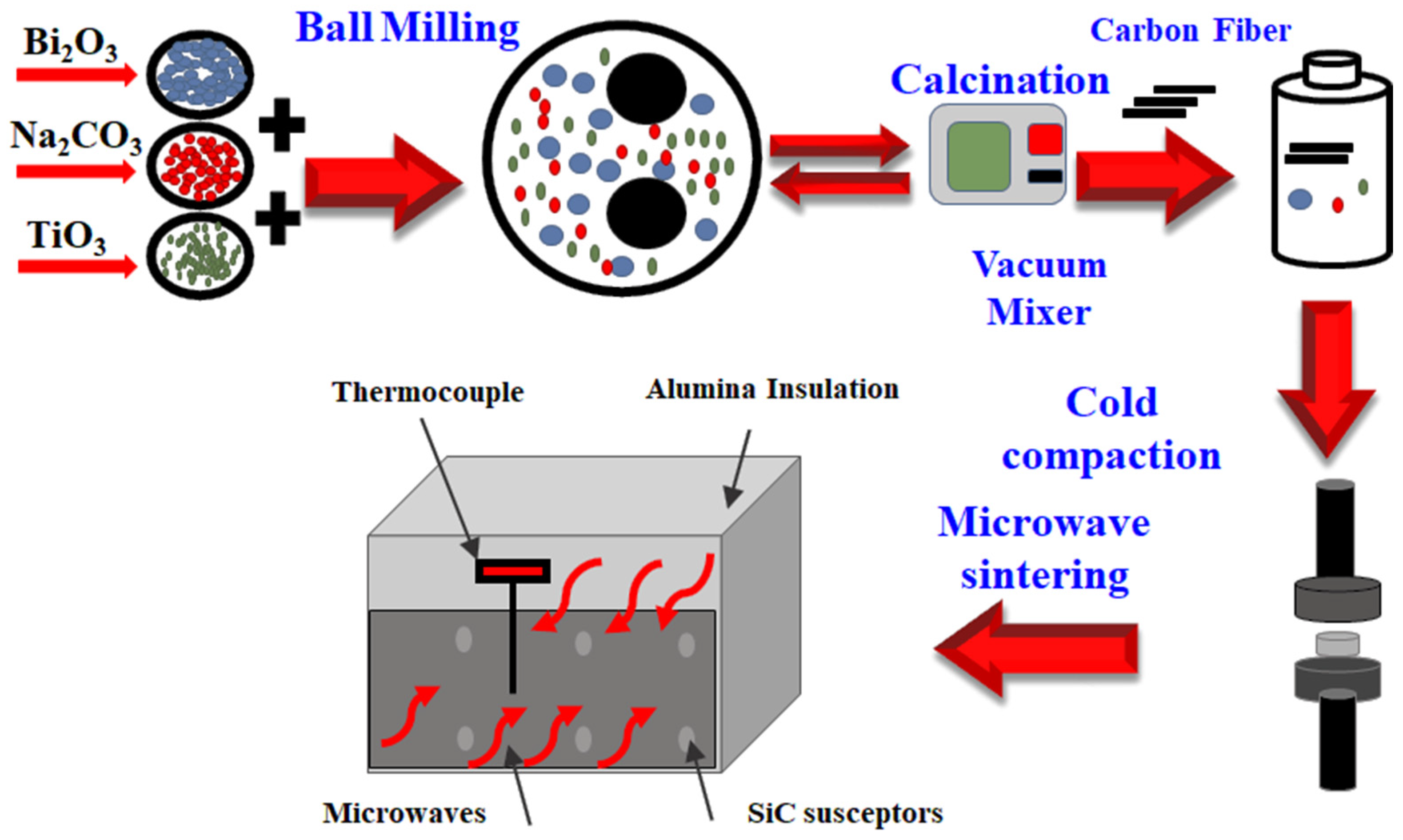
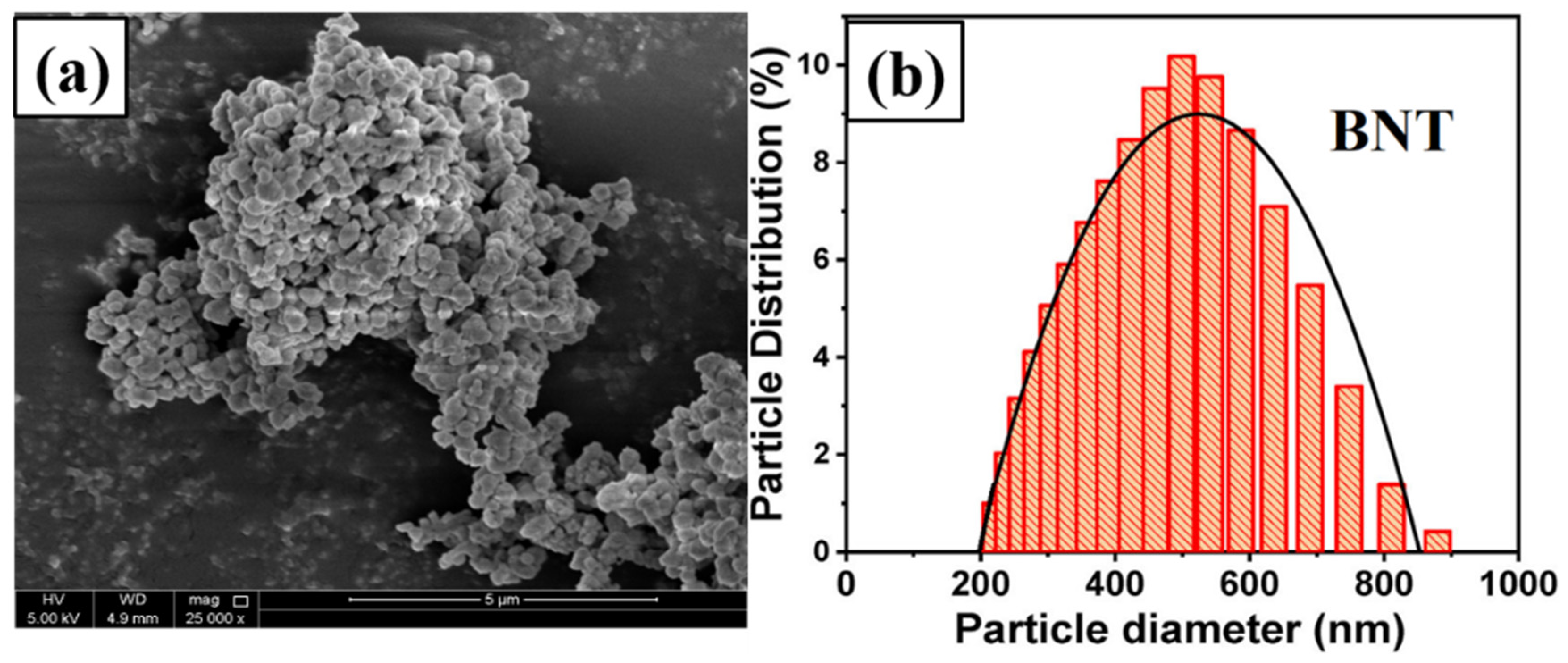
2.1. BNT Powder Preparation

BNT ceramics in pure form were synthesized using the standard method of solid-state reaction, which is a simple and economical method. Reagent-grade oxides of Na2CO3 (99.95%, Sigma Aldrich®, St. Louis, MO, USA), Bi2O3 (Sigma Aldrich® 99.9%), and TiO2 (Sigma Aldrich® 99.9%) were used as raw materials and weighed based on the stoichiometric calculation, i.e., Bi0.5Na0.5TiO3. The powder was dried at 200 °C for one hour before mixing to remove any moisture content. Then, a wet ball-milling process was used, where the mixture of powder was ball-milled in ethanol having a ball-to-powder ratio (BPR) of 20:1, and the ethanol-to-powder ratio was set at 5:1 for 4 h using ZrO2 balls with a ball-milling speed of 400 RPM. After the ball milling, the mixture was put into a jar where the balls were carefully removed by washing them with acetone in a syringe so that no powder would be stuck on the ZrO2 balls. After that, the jar, which contained the BNT powder, was kept in the oven for drying, and dried powder was obtained. Furthermore, the powder was calcined in a box furnace for 2 h at 850 °C at a heating rate of 10 °C/min, followed by cooling of the furnace. The calcined powder with the same parameters was ball-milled.

2.2. BNT-Carbon Fiber Composite

The carbon fibers (CFs) were initially chopped and sieved through two mesh-size sieves. They were thoroughly cleansed in an ultrasonic cleaner using ethanol. The resulting carbon fiber sizes obtained were approximately 60–70 µm. These fibers were mixed with BNT at different weight percentages by a vacuum mixer at a speed of 2000 RPM for 2 min with an interval of 30 secs for each composition. The final powder product had a composition of BNT with varying percentages of 0 wt.%, 0.5 wt.%, 1 wt.%, 2 wt.%, and 5 wt.% of carbon fibers. To create cylindrical pellets, the blended powder was mixed (~1.0 g) and then cold-compressed at 80 MPa for 90 s. The green pellets were 13 mm in diameter and 3 mm thick.
The microwave sintering was performed at 1000 °C with a 10 °C/min heating rate and held for 20 min at the peak temperature. Bi2O3 powder was sprinkled next to the green pellet to minimize bismuth loss during sintering to preserve the bismuth-rich environment. The oxides (Bi2O3) are more stable and can act as a buffer to reduce the vaporization of Bi during the sintering process. Furthermore, the spreading helps to maintain the stoichiometric balance of Bi in the BNT system. The sintered ceramic composites were gradually cooled in a furnace to prevent any quenching effects [34]. The density of composites was calculated using Archimedes’s Principle and found to be ~95%. Figure 1 schematically presents the steps involved in the synthesis of the carbon-fiber-reinforced Bi0.5Na0.5TiO3 composite (BNT-CF).

2.3. Characterization

The purity of BNT-CF was identified using an X-ray diffractometer (Rigaku. Miniflex 2 Desktop, Tokyo, Japan). The X-ray pattern was recorded within a range of 2θ = 20–80° at 45 kV and 40 mA using copper anode radiation with a 1.5°/min scanning rate and 0.02° step size. For the study of microstructure, polished sintered samples were examined by a Field Emission Scanning Electron Microscope (FESEM) using FE-SEM-Nova Nano-450, Breda, Netherlands. The surface morphology was studied by an Atomic Force Microscope (AFM) using an MFP-3D Asylum research (Santa Barbara, CA, USA) device equipped with a silicon probe (Al reflex coated Veeco model OLTESPA, Olympus, Tokyo, Japan) in contact mode. Raman Spectroscopy was carried out using Raman Thermo Scientific DXR3 Waltham, MA, USA. The mechanical properties of the sample were evaluated by attaching the MFP-3D nanoindenter to the AFM by using a Berkovich diamond indenter tip with the highest 1.00 mN indentation force. The values of nanoindentation were calculated from loading–unloading curves. The electric properties were calculated by a Precision LCR meter (Tonghui TH2829C, Bologna, Italy) with a range of 20 Hz–1 MHz.

3. Results and Discussions

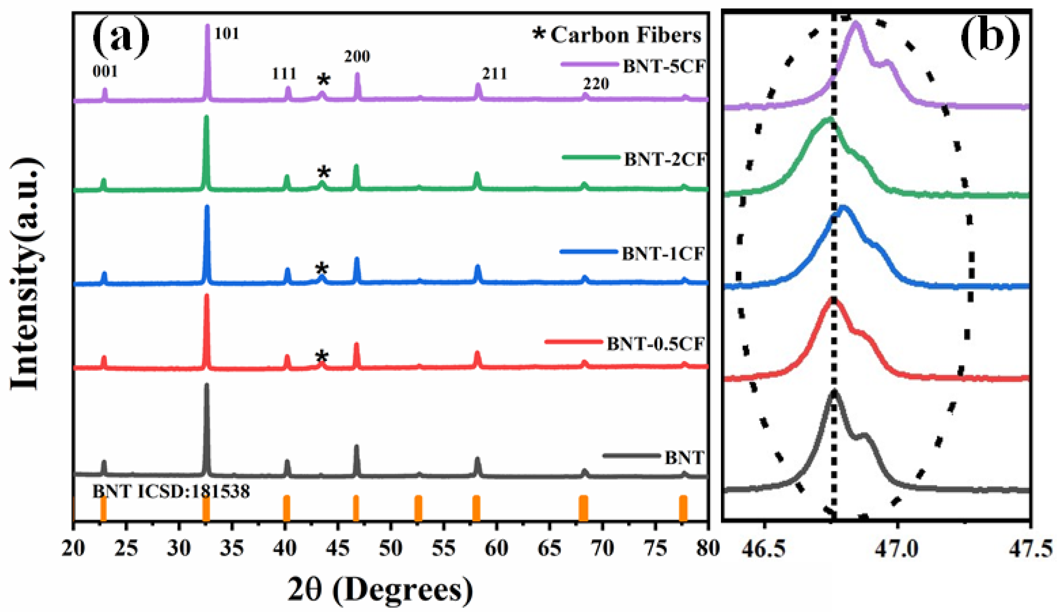
3.1. X-ray Diffraction

Figure 2 illustrates the X-ray diffraction analysis of the sintered BNT. In the sintered BNT, the crystalline phases were identified and indexed properly from the powder diffraction card (PDF) by JCPDS Card No: 36-0340. Usually, ABO3 perovskite shows diffraction peaks at (32°, 46°, and 58°).
It is evident that all the BNT samples are made of a single phase and clearly show typical ABO3 perovskite diffraction peaks at room temperature [35,36]. Moreover, the XRD pattern shows the existence of defined and sharp diffraction peaks, indicating the formation of well-defined and targeted sintered compositions. Figure 2a shows the XRD pattern of the microwave-sintered BNT-CF having varying compositions of carbon fiber (0.5%, 1%, 2%, and 5%). It is persistent that no additional phases were observed for the BNT ceramics when various amounts of carbon fiber were incorporated. This indicates that the carbon fiber has been dispersed properly into the BNT structure to produce a homogenous composite structure for all compositions [36]. Furthermore, the characteristic carbon peak appears at an angle of 43°, indicating the presence of carbon fiber in the BNT. The tetragonal structure exhibits a splitting of the (200) peak that was utilized to determine the presence of the Morphotropic Phase Boundary (MPB); the split peaks at 46–47° imply that a rhombohedral–tetragonal phase transition occurs, which can be noticeably seen in Figure 2b [36,37,38]. High piezoelectric properties are usually obtained from a stable MPB structure [39,40].

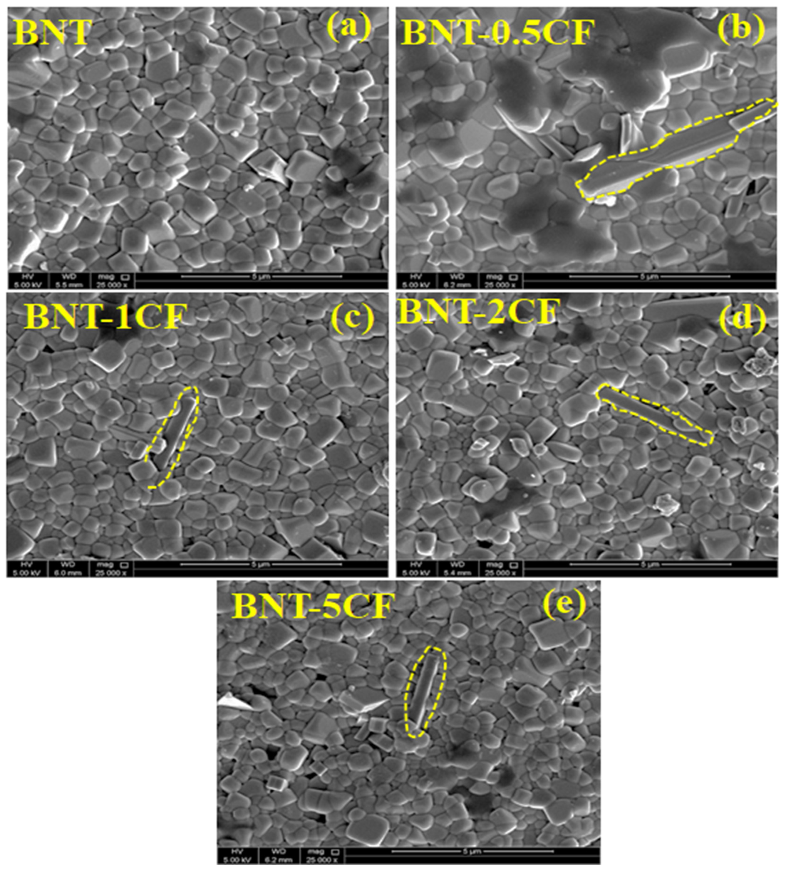
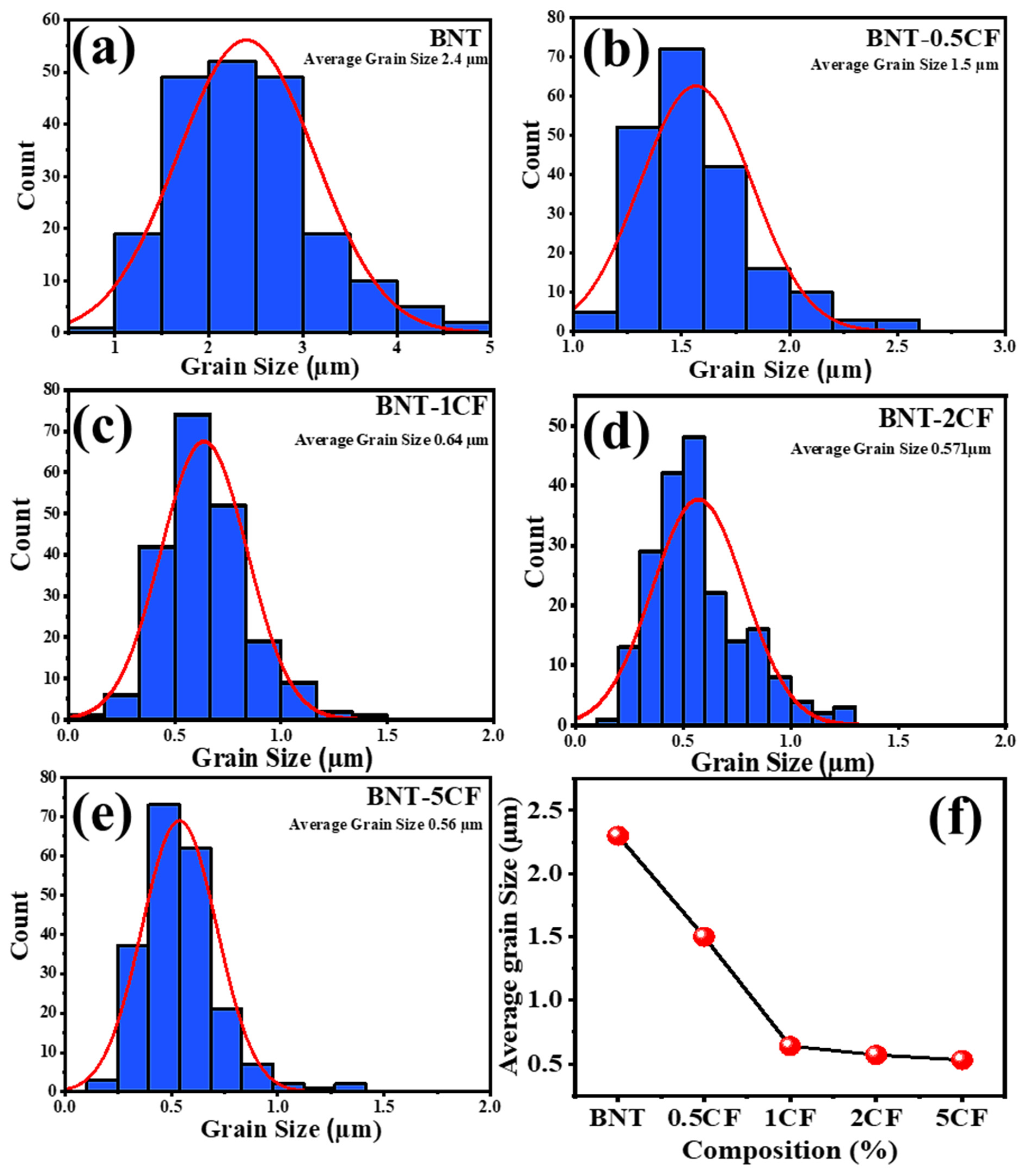
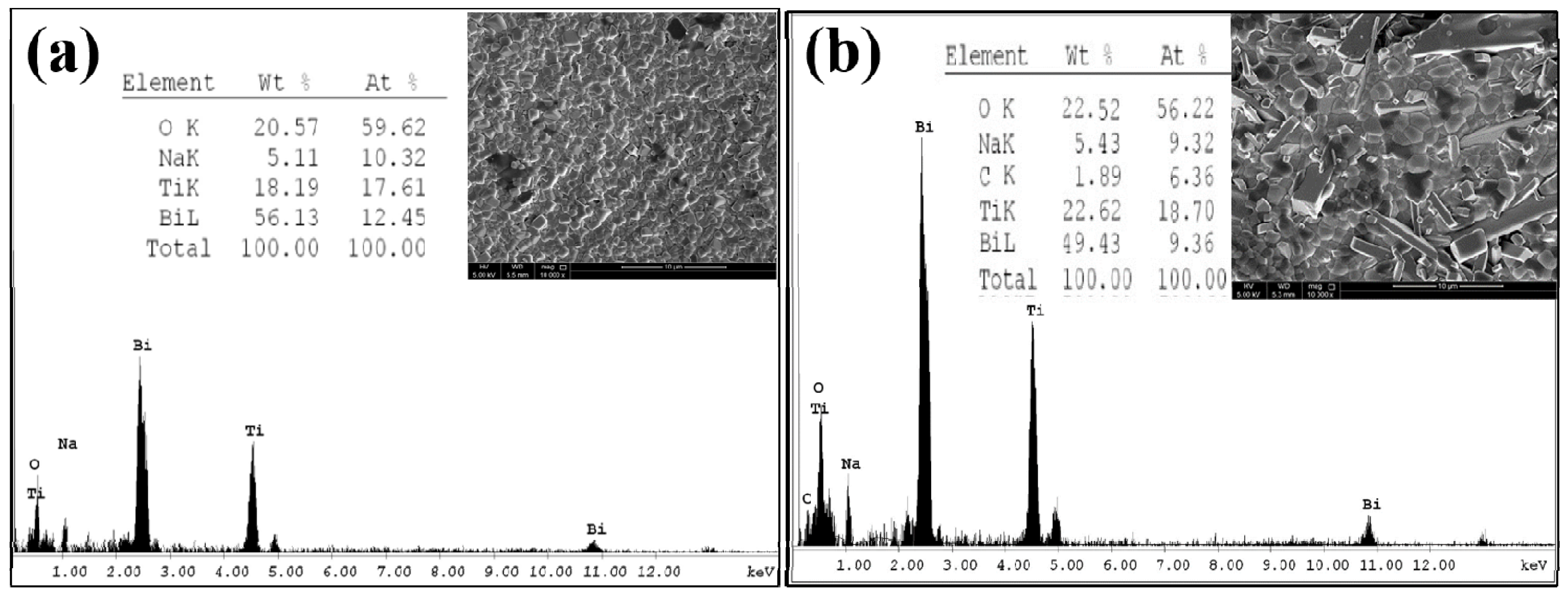
3.2. Scanning Electron Microscopy

Figure 3 displays the particle-size analysis of the BNT powder obtained after ball milling, which shows that the BNT powder has an average particle size of around 500 nm. Moreover, in Figure 4, the FE-SEM results revealed that all the BNT-CF samples were effectively dense and with fully developed rectangular grain shapes, which is typically observed in the microstructure of BNT piezoceramics. It can be noticed that a clear, round equiaxed grain and uniform grain size, without any cluster formation of carbon fibers, prevails in the BNT-CF samples. The carbon fiber is well integrated within the BNT structure while maintaining its individual existence with phase boundaries. Moreover, a comparison of the surface morphology of the BNT and BNT-CF with the carbon fiber composition ranging from x = 0 to 5 is also presented in Figure 4, showing the presence of a dense and compact structure. The grain sizes from the given micrographs were measured using ImageJ software (Version 1.54j), as shown in Figure 5. For the bare BNT, the average grain size is around 2.4 µm, and for the compositions x = 0.5, x = 1, x = 2, and x = 5, the average grain size decreases to 1.5 µm, 0.64 µm, 0.57 µm, and 0.56 µm.
It can be observed that by increasing the carbon fiber content in the BNT-CF, the grain size decreases. The restricted behavior of carbon fibers towards the grains makes it possible to reduce the grain size. This suggests that non-metallic CFs hindered the grain growth in the BNT. Furthermore, the grain growth rate (G) and nucleation (N) are the fundamental factors influencing grain growth. The grain growth rate and nucleation have opposing effects; a small ratio of N to G will result in a high final grain size, while a large ratio of N to G will result in a small final grain size. Therefore, the enhanced nucleation rate induced by the increased nucleation sites created by carbon fibers is mostly responsible for the reduction in grain size. Additionally, the CFs served as pinning points, which probably inhibited grain development at high temperatures [41].
In the microwave-sintered samples, the rapid heating rate of the microwaves prevented undesirable grain growth and provided more fine and uniformly distributed grains, which is considered to be an attractive feature for the processing of piezoelectric materials [42]. Incorporating a dense and uniform microstructure in the materials can greatly enhance their properties. The above discussion reveals that all the sintered BNT-CF samples demonstrate dense structure with minimum porosity.
An EDX analysis of the BNT and BNT-2CF was conducted to determine the sample’s elemental composition. The results are presented in Figure 6, which shows the peaks of Bi, Ti, Na, and O. In contrast, a new peak of carbon emerged in Figure 6b, which confirms the successful incorporation of the carbon into the BNT structure.

3.3. Raman Spectroscopy

In ceramics, the phase transition that occurs due to perovskite distortion can be detected by Raman Spectroscopy [43]. Moreover, this technique was deployed to detect the existence of the Morphotropic Phase Boundary (MPB). Figure 7 displays the Raman spectra for the BNT-CF containing different concentrations of CF from 100 to 1000 cm−1, showing six broad Raman peaks positioned at 137, 279, 529, 580, 758, and 834 cm−1, which is consistent with the already published results [44,45]. The width of the Raman spectra peak shows disorder on the A-site and overlapping of peaks. The peak appears at a lower Raman shift of 137 cm−1 labeled as peak A, showing vibrations of cations on the A-site in the ABO3 perovskite structure [46]. Peaks that appeared between 100 and 200 cm−1 correspond to the confirmed vibration bands of Bi-O and Na-O bonds, and the peak that appeared around 137 cm−1 is associated with the Na-O bond vibrations [47]. Wang et. al. reported that the band indicates the presence of local Na+TiO3 groups of multiple unit cells. Also, Bi-O bonds are not expected in this section, as Bi-O bonds must occur at <100 cm−1 because of the large Bi mass [37]. The Raman data demonstrate no substantial deviations in the Raman shift or magnitude of peak A with rising carbon fiber contents.
Peak B, centered at 280 cm−1, is consigned to Ti-O vibrations [48], whereas peaks C and D at ~529 cm−1 and 580 cm−1 are due to vibrations of TiO6 octahedra [49,50]. Broad peaks emerged from the overlapping of peaks, and disorder of the A-site happened due to the presence of various Bi3+ and Na+ ions [51]. The Raman spectra show that the centered peak B position at ~280 cm−1 slightly moves towards the higher Raman shift with the increasing addition of carbon fiber. This shift may be due to the structural disorder as well as the existence of oxygen vacancies in the system [49].
The modes that exist between the range of 450 and 650 cm−1 are changed after the addition of the CF. The splitting of the peak in region C indicates the presence of a mixed rhombohedral and tetragonal crystal structure that confirms the MPB nature [52]. The spectra at 529 cm−1 and 580 cm−1 are responsive to the deviations in structure from rhombohedral to tetragonal, according to the findings of research on another perovskite type of ceramics [50]. The splitting of these peaks becomes more prominent when the concentration of CF increases. These BNT-CFs at the aimed compositions exhibit an MPB nature, further supporting the XRD data (Figure 2). It is reported that a multi-structure in a solid solution improves dielectric and ferroelectric properties [53,54]. Apart from broadening and weakening in the frequency band between 700 and 900cm-1, no significant changes in composition are noticed for peaks E and F of the BNT. These bands are observed due to the shifting of O [55].

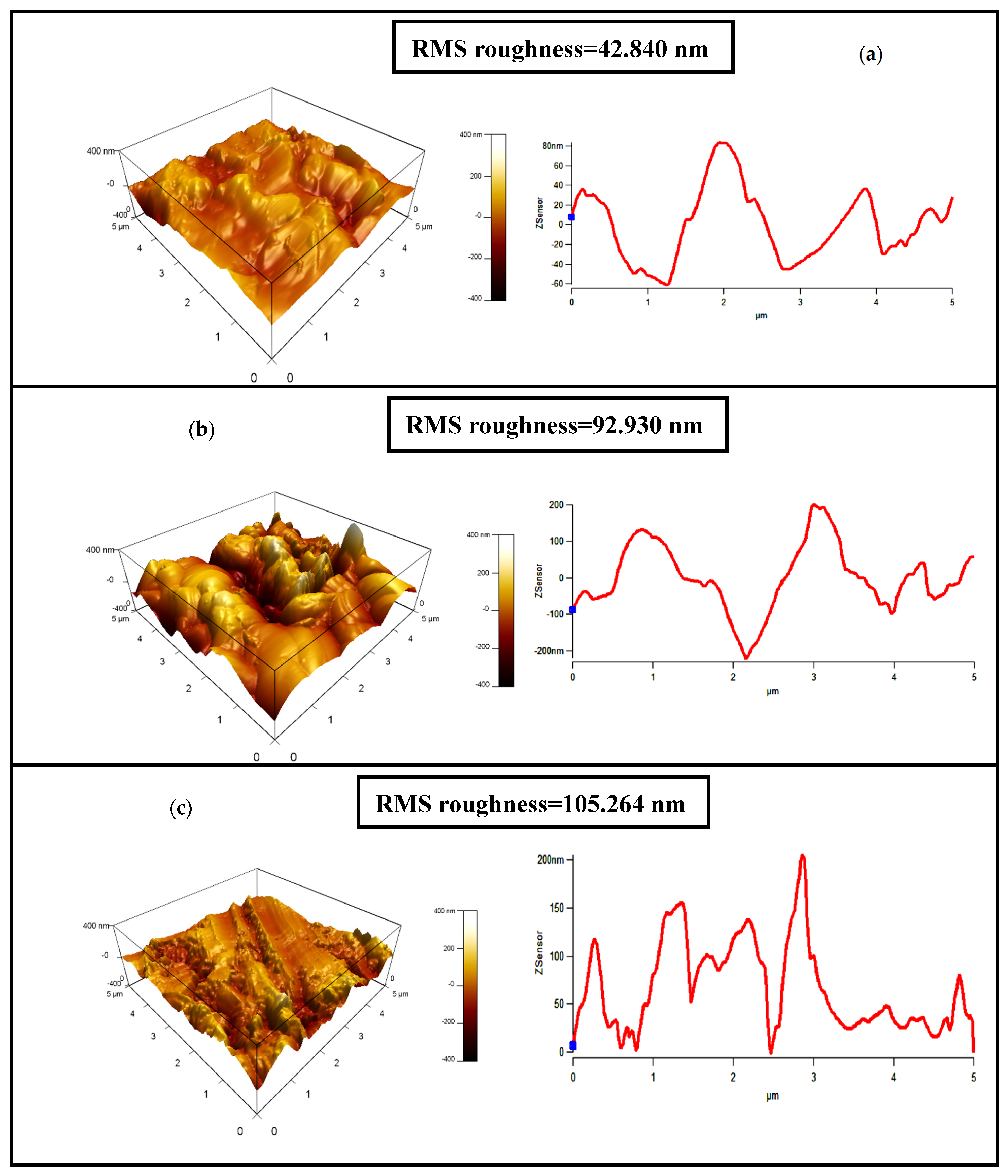
3.4. Atomic Force Microscopy
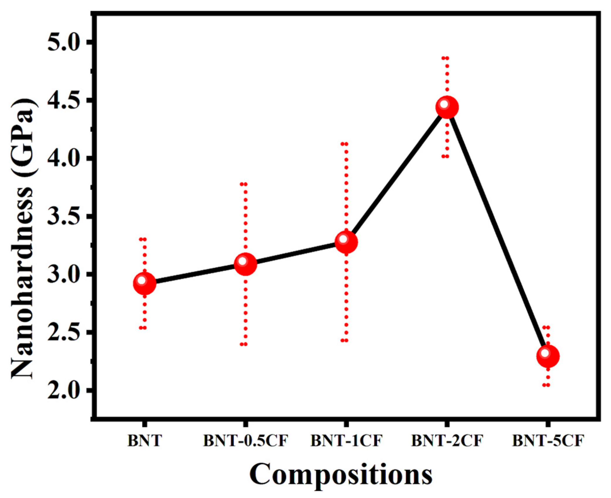
Figure 8 shows the surface topography of the BNT-CF containing different amounts of CF. The surface roughness of the BNT-CF increases with the increasing concentration of CF. The surface roughness value was analyzed by comparing the Root Mean Square (RMS) roughness parameter for the BNT and BNT-CF. The RMS value measured for the bare BNT is 42.840 nm, which presents a smooth surface. However, it is observed that the surface roughness of the BNT-CF increased due to the addition of carbon fiber, and a maximum value of 105.264 nm is achieved for the BNT-5CF.

3.5. Nanohardness

Figure 9 shows the nanohardness value for the BNT and BNT-CF with different concentrations of CF. It can be seen that the nanohardness gradually increases with the increasing content of CF. This increase may be due to the possibility of a dispersion hardening effect due to the presence of hard fibers [56]. Moreover, grain refinement also has a hardening effect because of the presence of CFs within the matrix [41]. Although the increase in CF concentration in the BNT structure helped to increase the hardness of the material, there is a significant drop in the BNT-5CF sample. This suggests that incorporating a high amount of carbon fibers may lead to a mismatch of reinforcing fibers and ceramic matrix, which results in stress concentrations, reduced load-bearing capacity, and, ultimately, lower nanohardness. This is also evident from the Atomic Force Microscopy, where the RMS value for the BNT-5CFs is greater than other compositions. The higher CF concentration significantly impacts the carbon fibers’ alignment within the ceramic matrix. If the fibers are not aligned properly or there is poor interfacial bonding between the ceramic and the fibers, nanohardness can be reduced.

3.6. Conductivity Study

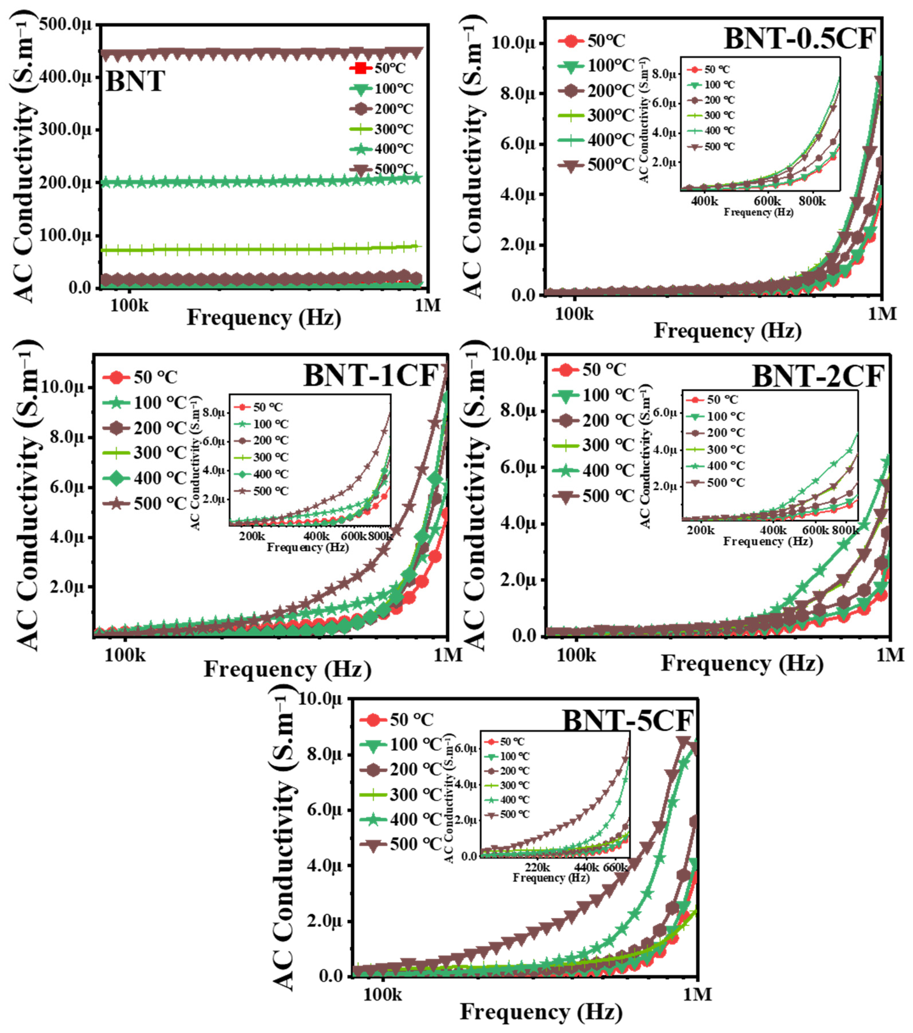
3.6.1. Effect of Frequency on Conductivity

The study of AC conductivity is valuable for gaining a better understanding of the compound’s electrical conductivity by examining its frequency dependency. The fluctuation in AC conductivity with frequency provides information about the behavior of charge carriers (electrons and holes).
To understand the basic feature, a plot is created between the AC conductivity (σac) and frequency at various temperatures. The conductivity value is acquired from the R by the relation
σ ac = l A R
where is thickness and A is the effective area of the material. The fluctuation in AC conductivity of the BNT-CF containing various concentrations of CF as a function of the frequency at various temperatures (50–500 °C) is presented in Figure 10.
For BNT, the conductivity is independent of frequency within this frequency range, so no change in conductivity is observed, even at a frequency value of 1 M Hz. The conductivity of BNT-CF increases at a frequency of 600 KHz by increasing the carbon fiber, and a further increase in carbon fiber results in a shift in the rise in conductivity at low frequency and elevated temperatures. For the BNT-5CF, an increase in conductivity occurs at 200 KHz. The region has little to no effect on frequency at lower temperatures, and then it smoothly relaxes to a strong dispersive region. A further increase in temperature causes broad dispersion in conductivity. At higher temperatures (400–500 °C), the conductivity curves narrow down and seem to merge. However, they did not merge completely. This phenomenon of merging the curves is due to the release of space charges [57].
Moreover, with the increase in temperature and frequency, the conductive ion returns to its original location due to less time and random collisions, making it a failed hop, resulting in failure. As a result, the ratio between successful and unsuccessful hops causes dispersion in conductivity at high frequencies and temperatures. Moreover, the structure transition occurs, providing unoccupied sites with more mobile ions at elevated temperatures. Increased AC conductivity with rising temperature indicates a Negative Temperature Coefficient of Resistance behavior (NTCR). The fluctuation in AC conductivity with temperature spikes after 300 °C. The data reported herein indicate the thermal activation of the conduction mechanism.
There is no significant increase in conductivity at the low-frequency regions for all temperature ranges. Conductivity curves at low frequencies give DC conductivity. The relaxation jump hypothesis helps to explain the observed frequency-independent σdc. Conduction occurs at low frequencies and high temperatures as charged particles bounce from one localized state to another. This leads to a wide range of translational motion of charge carriers, which increases σdc [58].

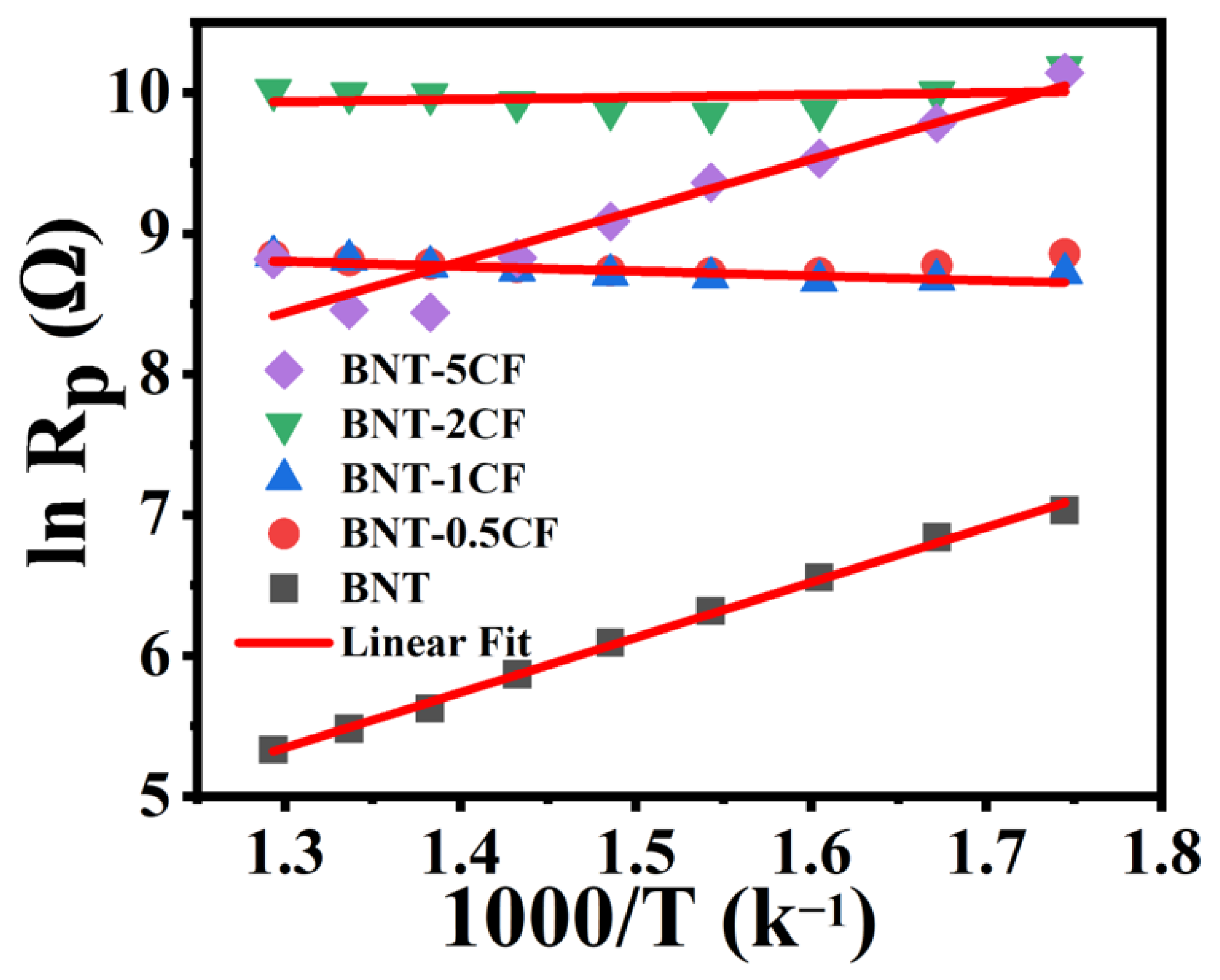
3.6.2. Activation Energy

Activation energies are calculated using the Arrhenius equation, as expressed below, to characterize the conduction mechanism at various frequencies.
This equation is τ = τo exp (Ea/kBT), where τo is the pre-exponential factor, Ea shows the activation energy for charge transfer, kB represents the Boltzmann constant (1.3807 × 10⁻²³ J K−1), and T stands for the absolute temperature. Table 1 shows the calculated activation energies of the sintered BNT-CF containing different concentrations of CF at various frequencies. The values of activation energy appeared to decrease at a high frequency value (1 MHz).
Figure 11 clearly shows that the value of the activation energy decreases with the addition of CF into the BNT-CF. This is due to the fact that carbon fibers are inherently electrically conductive because of the delocalized π-electrons in their structure. When carbon fibers are added to ceramic materials like BNT, they create pathways for the conduction of electrons, which causes a decrease in activation energy.
Carbon fibers can facilitate the movement of charged defects by providing pathways for electron conduction. This can enhance the mobility of ions or vacancies within the ceramic matrix. In ceramic materials, electrical conductivity can influence the migration of charged defects (such as ions or vacancies). It is observed that activation energy tends to drop up to a certain point, and a 5% addition of carbon fiber increased it again. Although the addition of CF in small amount can lower the activation energy by enhancing conductivity and facilitating charge transport, further additions beyond an optimal threshold can lead to detrimental effects such as overcrowding or the disruption of pathways critical for ion movement. These effects can ultimately result in an increase in activation energy, potentially returning it to levels similar to those observed in the absence of carbon fibers. The acquired results indicate that conduction is caused by a thermally stimulated process.

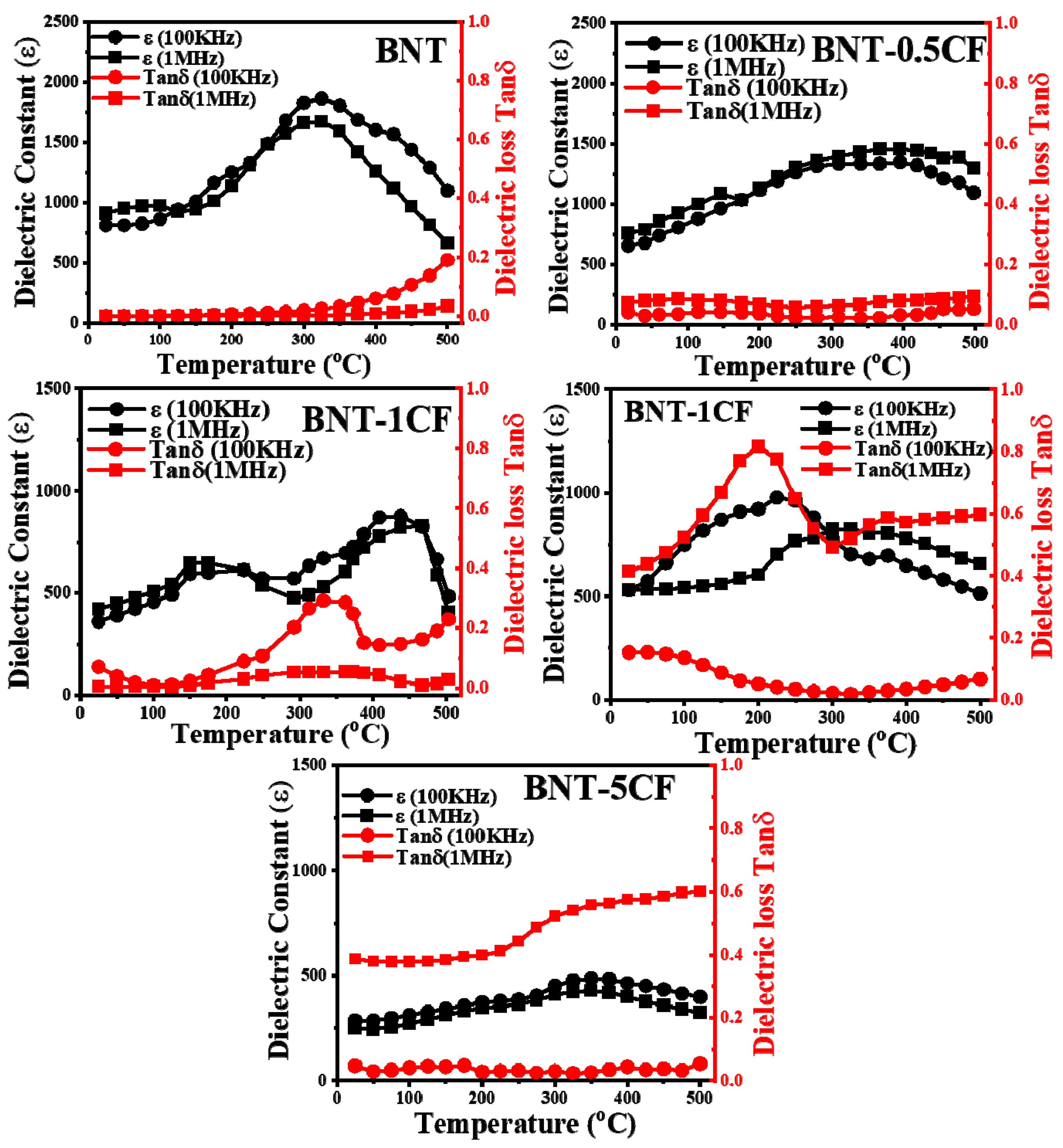
3.6.3. Dielectric Properties

The dielectric behavior strongly depends upon temperature and frequency [59,60]. Figure 12 illustrates the dielectric behavior of the BNT-CF containing different amounts of CF with respect to temperature at various frequencies. Two dielectric humps are observed in these graphs. The first anomaly is observed between room temperature and 180 °C, which can be termed the depolarization temperature (Td) [61], and the second is detected at temperatures above 320 °C. Where the dielectric constant value is maximum, that temperature is the maximum permittivity temperature (Tm) [47,62]. This shows that the increase in CF concentration has caused a decrease in dielectric properties at the frequency of 1 MHz. An increase in the carbon fiber content also increases the dielectric loss (Tanδ). It is illustrated in the graphs that tanδ rises with a temperature rise. The increase in tanδ is more significant at higher temperatures because of the high electrical conductivity. The movement of electric dipoles becomes maximum at high temperatures. At first, the dielectric loss is triggered by the interfacial properties of the composites; after that, the increase in carbon fibers causes a huge amount of heat generation during the polarization process, contributing to the dielectric loss. After a 2% addition of CF, the dielectric constant is half of its initial value because the excessive amount of fiber causes some escalation of the internal pores. Moreover, adding more CF content decreases the dielectric constant, and dielectric loss (tan δ) increases, signifying that the established percolation network is not steady and can be easily damaged by external frequency disturbances. The adjustment between the high values of the dielectric constant coupled with a low dielectric loss of compounds makes them ideal for various device applications.

4. Conclusions

A lead-free piezoelectric composite material (BNT-CF) was developed by reinforcing the Bi0.5Na0.5TiO3 (BNT) matrix with varying concentrations of carbon fiber (CF) by employing the microwave sintering technique. A structural analysis confirmed the formation of a phase-pure crystalline perovskite structure with a stable Morphotropic Phase Boundary (MPB). Microwave sintering of the BNT-CF at a low temperature and shorter dwell time results in superior densification and a more uniform microstructure with minimum porosity. The conductivity of the BNT-CF is influenced by the concentration of the CF, temperature, and frequency. The improvement in the electrical conductivity of the BNT-CF with increasing amounts of CF can be ascribed to the inherent high electrical conductivity of CF, which facilitates the movement of charged defects by providing pathways for electron conduction. Moreover, the dielectric properties of the BNT-CF are sensitive to the amount of CF; a gradual increase in the dielectric loss (Tanδ) and a decrease in the dielectric constant (ε) is noticed with the increase in CF. As a comparison, the BNT-CF with 2% carbon fiber exhibits optimal structural, mechanical, and dielectric properties.

Author Contributions

Conceptualization, F.A. (Fareeha Azam); data curation, F.A. (Fareeha Azam); investigation, F.A. (Fareeha Azam); methodology, F.A. (Fareeha Azam); software, F.A. (Fareeha Azam); writing—original draft, F.A. (Fareeha Azam); project administration, M.A.R.; supervision, M.A.R.; project administration, F.A. (Furqan Ahmed); resources, F.A. (Furqan Ahmed); resources, A.M.; review, A.M.; writing—review and editing, O.F.; formal analysis, O.F.; review, Z.I.; review, M.S.H.; supervision, R.A.S.; formal analysis, R.A.S.; validation, R.A.S.; resources, R.A.S. All authors have read and agreed to the published version of the manuscript.

Funding

This research received no external funding.

Data Availability Statement

The original contributions presented in the study are included in the article, further inquiries can be directed to the corresponding author/s.

Acknowledgments

The authors would like to acknowledge the Department of Metallurgy and Materials Engineering at the University of Engineering and Technology Lahore for providing an opportunity to conduct the current research work. The authors also acknowledge the technical support of the Center for Advanced Materials (CAM) and the Central Laboratory Unit (CLU) of Qatar University, Doha, Qatar. Special thanks are given to the University of Punjab, Lahore, for allowing us to use its vacuum centrifuge. The authors bear responsibility for the opinions stated in this article.

Conflicts of Interest

The authors declare no conflicts of interest.

References

  1. Milewski, J.; Dybiński, O.; Szczęśniak, A.; Martsinchyk, A.; Ćwieka, K.; Xing, W.; Szabłowski, Ł. Identification of Oxygen Ion Conductivity of Ba Doped Bi0.5Na0.5TiO3 (Ba-BNT) Based Matrix Impregnated by Lithium/Potassium Electrolyte for Molten Carbonate Fuel Cells. Int. J. Hydrog. Energy 2024, 51, 412–423. [Google Scholar] [CrossRef]
  2. Tan, J.; Huang, R.; Dai, Y.; Liang, Z.; Feng, J.; Lin, H.-T. Improvement of Electrostrain Properties of BNT-Based Piezoelectric Ceramics by Co-Doping of Sr2+Ta5+ in A and B Sites. Ceram. Int. 2023, 49, 35399–35405. [Google Scholar] [CrossRef]
  3. Manotham, S.; Jaita, P.; Butnoi, P.; Lertcumfu, N.; Rujijanagul, G. Improvements of Depolarization Temperature, Piezoelectric and Energy Harvesting Properties of BNT-Based Ceramics by Doping an Interstitial Dopant. J. Alloys Compd. 2022, 897, 163021. [Google Scholar] [CrossRef]
  4. Shi, J.; Zhao, Y.; Dong, R.; Tian, W.; Liu, X. Polarization Enhancement in Fe Doped BNT Based Relaxors Using Bi Compensation. J. Alloys Compd. 2021, 889, 161720. [Google Scholar] [CrossRef]
  5. Chen, B.; Tian, Y.; Lu, J.; Wu, D.; Qiao, X.; Liang, P.; Du, H.; Peng, Z.; Ren, X.; Chao, X.; et al. Ultrahigh Storage Density Achieved with (1-x)KNN-xBZN Ceramics. J. Eur. Ceram. Soc. 2020, 40, 2936–2944. [Google Scholar] [CrossRef]
  6. Sebastián, E.-G.; Raigoza, C.F.V.; Sonia, G.J. Structural and Magnetic Characterization of (1-x) KNN-xBLFO Ceramic Powders Obtained by the Combustion Reaction Method. J. Magn. Magn. Mater. 2020, 498, 166197. [Google Scholar] [CrossRef]
  7. Zhang, Y.; Li, M.; Li, H.; Zhai, J. Effects of CuO on KNN-Based Ceramics. Inorg. Chem. Commun. 2020, 122, 108299. [Google Scholar] [CrossRef]
  8. Amu-Darko, J.N.O.; Zhang, C.; Hussain, S.; Issaka, E.; Otoo, S.L.; Agyemang, M.F.; Okoroafor, E.C. Dielectric Properties and Relaxor Behavior of (1-x)Ba(Zr0.15Ti0.85)O3—xBa(Mg(1⁄3)Nb(2⁄3))O3 Ceramics for Capacitor Applications. Mater. Chem. Phys. 2022, 287, 126328. [Google Scholar] [CrossRef]
  9. Wang, Y.; Wang, H.; Xu, K.; Wang, B.; Wang, F.; Li, C.; Diao, C.; Huang, H.; Zheng, H. Significantly Improved Energy Storage Performance of Flexible PVDF-Based Nanocomposite by Loading Surface-Hydroxylated BaZr0.2Ti0.8O3 Nanofibers. Ceram. Int. 2022, 48, 16114–16122. [Google Scholar] [CrossRef]
  10. Qi, X.; Ren, P.; Tong, X. Effect of Heterovalent-Ion Doping and Oxygen-Vacancy Regulation on Piezoelectric Properties of KNN Based Lead-Free Ceramics. Ceram. Int. 2023, 49, 34795–34804. [Google Scholar] [CrossRef]
  11. Takenaka, T.; Kei-ichi Maruyama, K.M.; Koichiro Sakata, K.S. (Bi1/2N 1/2)TiO3-BaTiO3 System for Lead-Free Piezoelectric Ceramics. Jpn. J. Appl. Phys. 1991, 30, 2236. [Google Scholar] [CrossRef]
  12. Xu, Q.; Song, Z.; Tang, W.; Hao, H.; Zhang, L.; Appiah, M.; Cao, M.; Yao, Z.; He, Z.; Liu, H. Ultra-Wide Temperature Stable Dielectrics Based on Bi 0.5 Na 0.5 TiO3–NaNbO3 System. J. Am. Ceram. Soc. 2015, 98, 3119–3126. [Google Scholar] [CrossRef]
  13. Zhou, X.; Xue, G.; Luo, H.; Bowen, C.R.; Zhang, D. Phase Structure and Properties of Sodium Bismuth Titanate Lead-Free Piezoelectric Ceramics. Prog. Mater. Sci. 2021, 122, 100836. [Google Scholar] [CrossRef]
  14. Mahboob, S.; Prasad, G.; Kumar, G.S. Impedance Spectroscopy and Conductivity Studies on B Site Modified (Na0.5Bi0.5)(NdxTi1−2xNbx)O3 Ceramics. J. Mater. Sci. 2007, 42, 10275–10283. [Google Scholar] [CrossRef]
  15. Lian, H.; Liang, X.; Shi, M.; Liu, L.; Chen, X. Improved Dielectric Temperature Stability and Energy Storage Properties of BNT-BKT-Based Lead-Free Ceramics. Ceram. Int. 2024, 50, 5021–5031. [Google Scholar] [CrossRef]
  16. Bai, W.; Li, L.; Li, W.; Shen, B.; Zhai, J.; Chen, H. Effect of SrTiO3 Template on Electric Properties of Textured BNT–BKT Ceramics Prepared by Templated Grain Growth Process. J. Alloys Compd. 2014, 603, 149–157. [Google Scholar] [CrossRef]
  17. Devi, C.S.; Kumar, G.S.; Prasad, G. Control of Ferroelectric Phase Transition in Nano Particulate NBT–BT Based Ceramics. Mater. Sci. Eng. B 2013, 178, 283–292. [Google Scholar] [CrossRef]
  18. Machado, R.; Ochoa, D.A.; Dos Santos, V.B.; Cerdeiras, E.; Mestres, L.; García, J.E. High Stability of Properties in Morphotropic Phase Boundary Bi0.5Na0.5TiO3–BaTiO3 Piezoceramics. Mater. Lett. 2016, 183, 73–76. [Google Scholar] [CrossRef]
  19. Nagata, H.; Shinya, T.; Hiruma, Y.; Takenaka, T.; Sakaguchi, I.; Haneda, H. Piezoelectric Properties of Bismuth Sodium Titanate Ceramics. In Ceramic Transactions Series; Nair, K.M., Guo, R., Bhalla, A.S., Hirano, S., Suvorov, D., Eds.; Wiley: Hoboken, NJ, USA, 2006; Volume 167, pp. 213–221. ISBN 978-1-57498-188-9. [Google Scholar]
  20. Kainz, T.; Naderer, M.; Schütz, D.; Fruhwirth, O.; Mautner, F.A.; Reichmann, K. Solid State Synthesis and Sintering of Solid Solutions of BNT–xBKT. J. Eur. Ceram. Soc. 2014, 34, 3685–3697. [Google Scholar] [CrossRef]
  21. Julphunthong, P.; Bongkarn, T.; Maensiri, S. The Effect of Firing Temperatures on Phase Formation, Microstructure and Dielectric Properties of Bi0.5(Na0.74K0.16Li0.10)0.5TiO3 Ceramics Synthesized via the Combustion Route. Ceram. Int. 2015, 41, S143–S151. [Google Scholar] [CrossRef]
  22. Badapanda, T.; Venkatesan, S.; Panigrahi, S.; Kumar, P. Structure and Dielectric Properties of Bismuth Sodium Titanate Ceramic Prepared by Auto-Combustion Technique. Process. Appl. Ceram. 2013, 7, 135–141. [Google Scholar] [CrossRef]
  23. Pu, Y.; Zhang, L.; Cui, Y.; Chen, M. High Energy Storage Density and Optical Transparency of Microwave Sintered Homogeneous (Na0.5Bi0.5)(1–x)BaxTi(1–y)SnyO3 Ceramics. ACS Sustain. Chem. Eng. 2018, 6, 6102–6109. [Google Scholar] [CrossRef]
  24. Ramana, M.V.; Kiran, S.R.; Ramamanohar Reddy, N.; Siva Kumar, K.V.; Murthy, V.R.K.; Murty, B.S. Synthesis of Lead Free Sodium Bismuth Titanate (Nbt) Ceramic by Conventional and Microwave Sintering Methods. J. Adv. Dielectr. 2011, 01, 71–77. [Google Scholar] [CrossRef]
  25. Tian, L.; Nan, J.; Wang, H.; Shen, C. Effect of Microwave Sintering on the Properties of 0.95(Ca0.88Sr0.12) TiO30.05(Bi0.5Na0.5) TiO3 Ceramics. Materials 2019, 12, 803. [Google Scholar] [CrossRef] [PubMed]
  26. Agrawal, D.K. Microwave Processing of Ceramics. Curr. Opin. Solid State Mater. Sci. 1998, 3, 480–485. [Google Scholar] [CrossRef]
  27. Fukushima, H.; Mori, H.; Hatanaka, T.; Matsui, M. Properties and Microstructure of PZT Ceramics Sintered by Microwave. J. Ceram. Soc. Jpn. 1995, 103, 1011–1016. [Google Scholar] [CrossRef]
  28. Bandyopadhyay, P.; Ravi, D.; Ravichandran, R.; Mukhopadhyay, A.K. Carbon Fiber Reinforced Ceramics: A Flexible Material for Sophisticated Applications. In Advanced Flexible Ceramics; Elsevier: Amsterdam, The Netherlands, 2023; pp. 551–566. ISBN 978-0-323-98824-7. [Google Scholar]
  29. Liu, T.; Li, R.; Pei, J.; Xing, X.; Guo, Q. Effect of Different Fibers Reinforcement on the Properties of PZT/PVA Composites. Mater. Chem. Phys. 2020, 239, 122063. [Google Scholar] [CrossRef]
  30. Zhou, X.; Qi, H.; Yan, Z.; Xue, G.; Luo, H.; Zhang, D. Large Energy Density with Excellent Stability in Fine-Grained (Bi0.5Na0.5)TiO3-Based Lead-Free Ceramics. J. Eur. Ceram. Soc. 2019, 39, 4053–4059. [Google Scholar] [CrossRef]
  31. Tunkasiri, T.; Rujijanagul, G. Dielectric Strength of Fine Grained Barium Titanate Ceramics. J. Mater. Sci. Lett. 1996, 15, 1767–1769. [Google Scholar] [CrossRef]
  32. Xiong, Y.; Hu, J.; Nie, X.; Wei, D.; Zhang, N.; Peng, S.; Dong, X.; Li, Y.; Fang, P. One-Step Firing of Carbon Fiber and Ceramic Precursors for High Performance Electro-Thermal Composite: Influence of Graphene Coating. Mater. Des. 2020, 191, 108633. [Google Scholar] [CrossRef]
  33. Ahmad, I.; Yazdani, B.; Zhu, Y. Recent Advances on Carbon Nanotubes and Graphene Reinforced Ceramics Nanocomposites. Nanomaterials 2015, 5, 90–114. [Google Scholar] [CrossRef] [PubMed]
  34. Fan, Z.; Randall, C.A. An Overview of Oxygen Vacancy Dynamics in (1 − x)(Bi1/2Na1/2)TiO3xBaTiO3 Solid Solution. J. Mater. Chem. C 2021, 9, 10303–10308. [Google Scholar] [CrossRef]
  35. Rafiq, M.A.; Tkach, A.; Costa, M.E.; Vilarinho, P.M. Defects and Charge Transport in Mn-Doped K0.5Na0.5NbO3 Ceramics. Phys. Chem. Chem. Phys. 2015, 17, 24403–24411. [Google Scholar] [CrossRef]
  36. Jayakrishnan, A.R.; Alex, K.V.; Kamakshi, K.; Silva, J.P.B.; Sekhar, K.C.; Gomes, M.J.M. Enhancing the Dielectric Relaxor Behavior and Energy Storage Properties of 0.6Ba(Zr0.2Ti0.8)O30.4(Ba0.7Ca0.3)TiO3 Ceramics through the Incorporation of Paraelectric SrTiO3. J. Mater. Sci. Mater. Electron. 2019, 30, 19374–19382. [Google Scholar] [CrossRef]
  37. Wang, J.; Zhou, Z.; Xue, J. Phase Transition, Ferroelectric Behaviors and Domain Structures of (Na1/2Bi1/2)1−xTiPbxO3 Thin Films. Acta Mater. 2006, 54, 1691–1698. [Google Scholar] [CrossRef]
  38. Shan, D.; Qu, Y.; Song, J. Ionic Doping Effects on Crystal Structure and Relaxation Character in Bi0.5Na0.5TiO3 Ferroelectric Ceramics. J. Mater. Res. 2007, 22, 730–734. [Google Scholar] [CrossRef]
  39. Yoon, M.-S.; Khansur, N.H.; Ur, S.-C. The Effect of Pre-Milling/Pre-Synthesis Process and Excess Ba on the Microstructure and Dielectric/Piezoelectric Properties of Nano-Sized 0.94[(Bi0.5Na0.5)TiO3]–0.06[Ba(1+x)TiO3]. Ceram. Int. 2010, 36, 1265–1275. [Google Scholar] [CrossRef]
  40. Bai, W.; Li, P.; Li, L.; Zhang, J.; Shen, B.; Zhai, J. Structure Evolution and Large Strain Response in BNT–BT Lead-Free Piezoceramics Modified with Bi(Ni0.5Ti0.5)O3. J. Alloys Compd. 2015, 649, 772–781. [Google Scholar] [CrossRef]
  41. Kandemir, S.; Bohlen, J.; Dieringa, H. Influence of Recycled Carbon Fiber Addition on the Microstructure and Creep Response of Extruded AZ91 Magnesium Alloy. J. Magnes. Alloys 2023, 11, 2518–2529. [Google Scholar] [CrossRef]
  42. Hao, X. A Review on the Dielectric Materials for High Energy-Storage Application. J. Adv. Dielectr. 2013, 03, 1330001. [Google Scholar] [CrossRef]
  43. Prado, A.; Ramajo, L.; Camargo, J.; Del Campo, A.; Öchsner, P.; Rubio-Marcos, F.; Castro, M. Stabilization of the Morphotropic Phase Boundary in (1 − x)Bi0.5Na0.5TiO3–xBaTiO3 Ceramics through Two Alternative Synthesis Pathways. J. Mater. Sci. Mater. Electron. 2019, 30, 18405–18412. [Google Scholar] [CrossRef]
  44. Sahoo, S.; Hajra, S.; De, M.; Choudhary, R.N.P. Resistive, Capacitive and Conducting Properties of Bi0.5Na0.5TiO3-BaTiO3 Solid Solution. Ceram. Int. 2018, 44, 4719–4726. [Google Scholar] [CrossRef]
  45. Prado, A.; Rubio-Marcos, F.; Ramajo, L.; Castro, M.S. Dielectric and Ferroelectric Properties Evolution of (1−x)(Bi0.5Na0.5TiO3)–xK0.5Na0.5NbO3 Piezoceramics. Bull. Mater. Sci. 2020, 43, 282. [Google Scholar] [CrossRef]
  46. Lidjici, H.; Lagoun, B.; Berrahal, M.; Rguitti, M.; Hentatti, M.A.; Khemakhem, H. XRD, Raman and Electrical Studies on the (1−x)(Na0.5Bi0.5)TiO3−xBaTiO3 Lead Free Ceramics. J. Alloys Compd. 2015, 618, 643–648. [Google Scholar] [CrossRef]
  47. Nesterović, A.; Vukmirović, J.; Stijepović, I.; Milanović, M.; Bajac, B.; Tóth, E.; Cvejić, Ž.; Srdić, V.V. Structure and Dielectric Properties of (1-x)Bi0.5Na0.5TiO3–x BaTiO3 Piezoceramics Prepared Using Hydrothermally Synthesized Powders. R. Soc. Open Sci. 2021, 8, 202365. [Google Scholar] [CrossRef]
  48. Alaoui, I.H.; Lemée, N.; Le Marrec, F.; Mebarki, M.; Cantaluppi, A.; Favry, D.; Lahmar, A. Effect of Oxygen Annealing Atmosphere on Structural, Electrical and Energy Storage Properties of Bi0.5Na0.5TiO3 Polycrystalline Thin Film. Quantum Beam Sci. 2023, 7, 29. [Google Scholar] [CrossRef]
  49. Anthoniappen, J.; Tu, C.S.; Chen, P.-Y.; Chen, C.-S.; Idzerda, Y.U.; Chiu, S.-J. Raman Spectra and Structural Stability in B-Site Manganese Doped (Bi0.5Na0.5)0.925Ba0.075TiO3 Relaxor Ferroelectric Ceramics. J. Eur. Ceram. Soc. 2015, 35, 3495–3506. [Google Scholar] [CrossRef]
  50. Rout, D.; Moon, K.-S.; Kang, S.-J.L.; Kim, I.W. Dielectric and Raman Scattering Studies of Phase Transitions in the (100−x)Na0.5Bi0.5TiO3–xSrTiO3 System. J. Appl. Phys. 2010, 108, 084102. [Google Scholar] [CrossRef]
  51. Kreisel, J.; Glazer, A.M.; Bouvier, P.; Lucazeau, G. High-Pressure Raman Study of a Relaxor Ferroelectric: The Na0.5Bi0.5TiO3 Perovskite. Phys. Rev. B 2001, 63, 174106. [Google Scholar] [CrossRef]
  52. Liu, X.; Zhai, J.; Shen, B. Local Phenomena in Bismuth Sodium Titanate Perovskite Studied by Raman Spectroscopy. J. Am. Ceram. Soc. 2018, 101, 5604–5614. [Google Scholar] [CrossRef]
  53. Trelcat, J.-F.; Courtois, C.; Rguiti, M.; Leriche, A.; Duvigneaud, P.-H.; Segato, T. Morphotropic Phase Boundary in the BNT–BT–BKT System. Ceram. Int. 2012, 38, 2823–2827. [Google Scholar] [CrossRef]
  54. Yan, K.; Ren, S.; Fang, M.; Ren, X. Crucial Role of Octahedral Untilting R3m/P4Mm Morphotropic Phase Boundary in Highly Piezoelectric Perovskite Oxide. Acta Mater. 2017, 134, 195–202. [Google Scholar] [CrossRef]
  55. Parmar, K.; Negi, N.S. Influence of Na/Bi Excess on Structural, Dielectric and Multiferroic Properties of Lead Free (Na0.5Bi0.5)0.99La0.01Ti0.988Fe0.012O3 Ceramic. J. Alloys Compd. 2015, 618, 781–787. [Google Scholar] [CrossRef]
  56. Ureña, A.; Rams, J.; Escalera, M.D.; Sánchez, M. Characterization of Interfacial Mechanical Properties in Carbon Fiber/Aluminium Matrix Composites by the Nanoindentation Technique. Compos. Sci. Technol. 2005, 65, 2025–2038. [Google Scholar] [CrossRef]
  57. Pattanayak, R.; Panigrahi, S.; Dash, T.; Muduli, R.; Behera, D. Electric Transport Properties Study of Bulk BaFe12O19 by Complex Impedance Spectroscopy. Phys. B Condens. Matter 2015, 474, 57–63. [Google Scholar] [CrossRef]
  58. Kanuru, S.R.; Baskar, K.; Dhanasekaran, R. Synthesis, Structural, Morphological and Electrical Properties of NBT–BT Ceramics for Piezoelectric Applications. Ceram. Int. 2016, 42, 6054–6064. [Google Scholar] [CrossRef]
  59. Nie, X.; Wang, J.; Peng, Z.; Chai, Q.; Zhou, Q.; Chao, X.; Yang, Z. High Transparency and Good Electric Properties in Low Symmetry BNT-Based Ceramics. Solid State Sci. 2022, 129, 106906. [Google Scholar] [CrossRef]
  60. Schulz, T.; Veerapandiyan, V.; Deluca, M.; Töpfer, J. Synthesis and Properties of Lead-Free BNT-BT-xCZ Ceramics as High-Temperature Dielectrics. Mater. Res. Bull. 2022, 145, 111560. [Google Scholar] [CrossRef]
  61. Liu, Y.; Ji, Y.; Yang, Y. Growth, Properties and Applications of Bi0.5Na0.5TiO3 Ferroelectric Nanomaterials. Nanomaterials 2021, 11, 1724. [Google Scholar] [CrossRef]
  62. Arya, B.B.; Choudhary, R.N.P. Studies of Structural and Electrical Characteristics of Multi-Substituted Bi0.5Na0.5TiO3 Ferroelectric Ceramics. J. Mater. Sci. Mater. Electron. 2021, 32, 11547–11567. [Google Scholar] [CrossRef]
Figure 1. A schematic representation of BNT–carbon fiber composite formation.
Crystals 14 00798 g001
Figure 2. (a) X-ray diffraction pattern of BNT-CFs microwave-sintered at 1000 °C for 20 min in 2θ ranges from 20 to 80°; (b) the magnifying image of splitting peaks in the range of 45–48°.
Crystals 14 00798 g002
Figure 3. (a) FE-SEM images of BNT powder synthesized using a ball mill; (b) particle-size analysis of BNT powder.
Crystals 14 00798 g003
Figure 4. FE-SEM micrographs of surfaces for (a) BNT, (b) BNT-0.5CF, (c) BNT-1CF, (d) BNT-2CF, and (e) BNT-5CF composites sintered at 1000 °C for 20 min with varying compositions of carbon fibers.
Crystals 14 00798 g004
Figure 5. (a) BNT, (b) BNT-0.5CF, (c) BNT-1CF, (d) BNT-2CF, (e) BNT-5CF, and (f) the reduction in grain size with increasing carbon fiber content.
Crystals 14 00798 g005
Figure 6. EDX analysis of (a) BNT and (b) BNT-2CF composites.
Crystals 14 00798 g006
Figure 7. Raman spectra for the synthesized compositions of BNT-CF at room temperature.
Crystals 14 00798 g007
Figure 8. The AFM images and roughness value of BNT-CF compositions: (a) BNT; (b) BNT-0.5CF; and (c) BNT-5CF.
Crystals 14 00798 g008
Figure 9. Nanohardness value of BNT-CF with varying compositions of CF.
Crystals 14 00798 g009
Figure 10. Variation in AC conductivity with respect to frequency at various temperatures.
Crystals 14 00798 g010
Figure 11. Arrhenius plot of ln resistance vs. 1/temperature.
Crystals 14 00798 g011
Figure 12. Dielectric properties of BNT-CF containing different concentrations of CF with varying frequency and temperature ranges.
Crystals 14 00798 g012
Table 1. Activation energy for sintered composite samples at 1 MHz.
SR. NumberSampleEa
1.BNT0.34
2.BNT-0.5CF0.15
3.BNT-1CF0.1
4.BNT-2CF0.03
5.BNT-5CF0.33
Disclaimer/Publisher’s Note: The statements, opinions and data contained in all publications are solely those of the individual author(s) and contributor(s) and not of MDPI and/or the editor(s). MDPI and/or the editor(s) disclaim responsibility for any injury to people or property resulting from any ideas, methods, instructions or products referred to in the content.

