Article

Microstructural Stability and Creep Behavior of a Re/Ru Single-Crystal Nickel-Based Alloy

Department of Mechanical and Electronic Engineering, Guizhou Communications Polytechnic University, Guiyang 551400, China
Crystals 2025, 15(4), 370; https://doi.org/10.3390/cryst15040370
Submission received: 3 February 2025 / Revised: 6 April 2025 / Accepted: 7 April 2025 / Published: 17 April 2025
(This article belongs to the Special Issue Microstructure and Mechanical Properties of Alloys and Composites)

Abstract

:
By testing the creep properties of a Re/Ru-containing single-crystal alloy specimen and examining the microstructural evolution of the allow at different stages of creep using scanning electron microscopy (SEM) and transmission electron microscopy (TEM), the deformation and damage mechanisms of the alloy under ultra-high temperature conditions were investigated. It was observed that a dislocation network forms before the rafting of the γ′ phase. As creep progresses, this network becomes increasingly dense and complete. Moreover, the dislocation network undergoes a transformation from the <110>-type to the <100>-type configuration, with a hybrid <110>-<100>-type network representing an intermediate state during the transition. Stacking faults were also identified within the γ′ phase, suggesting that the stacking fault energy of this alloy is lower compared to that of other alloys. During creep, dislocations that penetrate the γ′ phase can undergo cross slip from the {111} plane to the {100} plane under applied stress, resulting in the formation of Kear–Wilsdorf (K–W) immobile dislocation locks. These locks hinder further dislocation movement within the γ′ phase. It is concluded that the damage mechanism of the alloy at the later stage of creep under 120 MPa/1160 °C involves initial crack formation at the interface of the twisted raft-like γ/γ′ two-phase structure. As creep continues, the crack propagates in a direction perpendicular to the applied stress axis.

1. Introduction

Single-crystal high-temperature alloys are primarily composed of the γ (Ni) matrix phase and the γ′ (Ni₃Al) strengthening phase. The primary strengthening mechanisms include solid solution strengthening within the γ/γ′ two-phase structure, anomalous yield strengthening of the γ′ phase, and γ/γ′ interfacial strengthening [1]. These alloys exhibit excellent high-temperature mechanical properties, fatigue resistance, and overall reliability [2]. With the ongoing advancement in thrust-to-weight ratios in aero-engines, turbine inlet temperatures have reached 2000–2200 K. This increase imposes more stringent performance requirements on single-crystal turbine blades, which are the critical hot-end components of the engine [3,4]. To meet these demands, alloy performance is commonly improved by adding heavy elements such as W, Re, and Ru [5]. Among these, rhenium (Re) is particularly notable for significantly enhancing creep resistance. However, an excessive Re content can lead to the formation of topologically close-packed (TCP) phases and elemental segregation [6,7]. To address this issue, ruthenium (Ru) is introduced into Re-containing nickel-based alloys due to its ability to mitigate elemental segregation, thereby enhancing microstructural stability. As a result, the relationship between microstructure and properties of Re/Ru-containing alloys before and after creep has attracted widespread attention from researchers worldwide [8,9].
Dislocation movement and its modes play a crucial role in both plastic deformation and creep fracture behavior. When dislocations on different slip planes meet at the γ/γ′ interface, a dislocation network forms. These interfacial networks are not static and can evolve into different configurations over time [10,11]. The observable dislocation networks in single-crystal alloys are typically classified into three types: (1) <110>-type networks composed of dislocations along the <110> direction; (2) <110>-<100> mixed networks with dislocations in both the <110> and <100> directions; and (3) <100>-type networks composed entirely of <100> dislocations. Each type differs in its formation mechanism and morphology, with the <100>-type network having the smallest spacing [12,13]. During creep, dislocation networks hinder the motion of dislocation in the γ matrix and suppress emissions from dislocation sources. This effect contributes to enhanced creep resistance and mechanical performance, ultimately extending the service life of the alloy [14,15]. Moreover, the formation and transformation of dislocation networks help reduce lattice mismatch between γ and γ′ phases. The extent of mismatch influences both the type and density of interfacial dislocation networks [16]. Studies have shown that dislocation networks that are more regular and closely spaced more effectively impede dislocation penetration into the γ′ phase, thereby improving alloy properties. However, for specific alloys, an optimal combination of dislocation type and spacing exists. For instance, the TMS-162 alloy exhibits superior creep resistance when its dislocation network forms a regular rectangular pattern with a spacing of 27 nm [17,18]. The addition of Re increases both lattice mismatch and mismatch-induced stress between the γ and γ′ phases, refining the dislocation network and further enhancing creep resistance [19,20]. Therefore, the type and spacing of interfacial dislocation networks are critical factors influencing creep behavior. Nonetheless, the formation process, types, and morphologies of such networks during ultrahigh-temperature creep in Re/Ru-containing alloys remain unclear.
As creep progresses, the dislocation network eventually degrades. At this stage, dislocations generated in the γ matrix channel can shear into the γ′ phase, forming various fault structures such as superlattice intrinsic stacking faults (SISFs), complex fault structures (CFSs), and anti-phase boundaries (APBs) [21]. The individual addition of Re and Ru, both of which have large atomic radii, reduces the alloy’s stacking fault energy. This leads to the formation of numerous stacking faults during creep [2]. It becomes increasingly difficult for the leading and trailing segments of dislocations to recombine into complete dislocations for continued movement [22]. These stacking faults impede dislocation motion, thereby enhancing creep resistance. Consequently, a greater density of stacking faults during creep typically correlates with improved mechanical properties [23]. However, the creep behavior and microstructural stability of Re/Ru alloys at ultrahigh temperatures—particularly the evolution of dislocation networks and the motion or decomposition of dislocations within the γ′ phase—remain insufficiently understood. Given the close link between deformation and damage mechanisms, and the fact that creep damage is the primary failure mode of single-crystal alloys in service, understanding the relationship between deformation processes and crack initiation and propagation under ultrahigh-temperature conditions is critical.
Based on these considerations, this study investigates the creep properties and microstructural evolution of Re/Ru-containing nickel-based single-crystal alloys through creep testing and microstructural characterization. Special emphasis is placed on the formation and transformation of interfacial dislocation networks and the diffraction contrast analysis of dislocation configurations, with the aim of revealing their deformation and damage mechanisms under ultrahigh-temperature conditions.

2. Experimental Procedures

In this study, a single-crystal high-temperature alloy containing 6% Re and 5% Ru was selected as the research subject. The alloy composition was designed based on predictions of TCP (topologically close-packed) phase precipitation tendencies, using the electron vacancy number method and the d-electron energy level method. The detailed composition is presented in Table 1. The single-crystal rods were fabricated at the Institute of Metal Research, Chinese Academy of Sciences. The process began with melting the master alloy in a vacuum induction melting furnace. Subsequently, a vacuum high-gradient directional solidification furnace was used to produce [001]-oriented single-crystal alloy bars (16 mm in diameter and 180 mm in length) via the crystal selection technique. The heat treatment procedure for the as-cast alloy was as follows: 1300 °C for 2 h, 1310 °C for 6 h, 1315 °C for 10 h, 1323 °C for 10 h, 1328 °C for 10 h, and 1332 °C for 5 h, all followed by air cooling. This was followed by a solution-aging treatment at 1180 °C for 4 h (air cooled) and a final aging treatment at 870 °C for 24 h (air cooled).
After the complete heat treatment process, the test bars were cut into plate-shaped specimens with a 20 mm pitch and a cross-section of 4.5 mm × 2.5 mm using wire electrical discharge machining (EDM). Creep tests were conducted under a constant stress of 120 MPa. During testing, a high-temperature fixture was made of the same alloy material, which also served as a wear component, enabling high-temperature creep testing. To examine the microstructure and morphology at various stages of creep, and to identify the dislocation configuration characteristic at each stage, specimens were subjected to instantaneous air cooling at selected creep times. Scanning electron microscopy (SEM) specimens were prepared through a three-step process: grinding, polishing, and etching. (1) Grinding: Sandpapers of varying coarseness were used to remove both the molten layer produced by wire cutting and the high-temperature oxide layer formed during the creep process. (2) Polishing: Mechanical polishing was carried out using diamond abrasive paste with a particle size of 0.5 μm. (3) Etching: The samples were etched in a solution containing 20 g CuSO₄, 5 mL H₂SO₄, 100 mL HCl, and 80 mL H₂O. Transmission electron microscopy (TEM) specimens were prepared via rough grinding, punching, fine grinding, and twin-jet electropolishing. (1) Rough grinding: The sample was ground to a thickness of approximately 60 μm using sandpaper. (2) Punching: A disk of 3 mm in diameter was punched from the thinned sample using a precision punch. (3) Fine grinding: The disk was further ground using fine sandpaper to a final thickness of approximately 40 μm. (4) Twin-jet electropolishing: Final thinning was performed using a twin-jet electrolytic polishing apparatus in a solution of 10% perchloric acid and 90% ethanol at −30 °C and a 30 mA current.

3. Analysis of Test Results

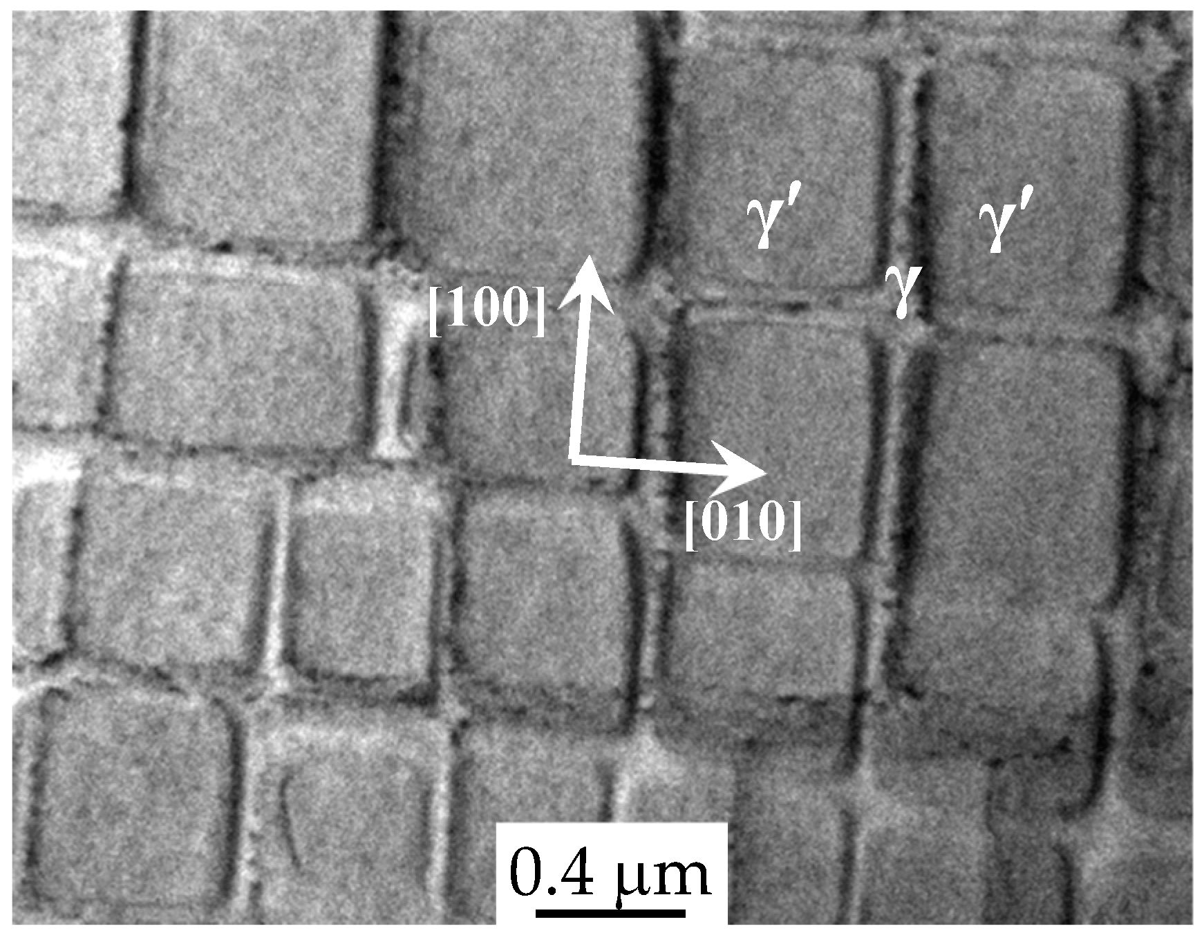
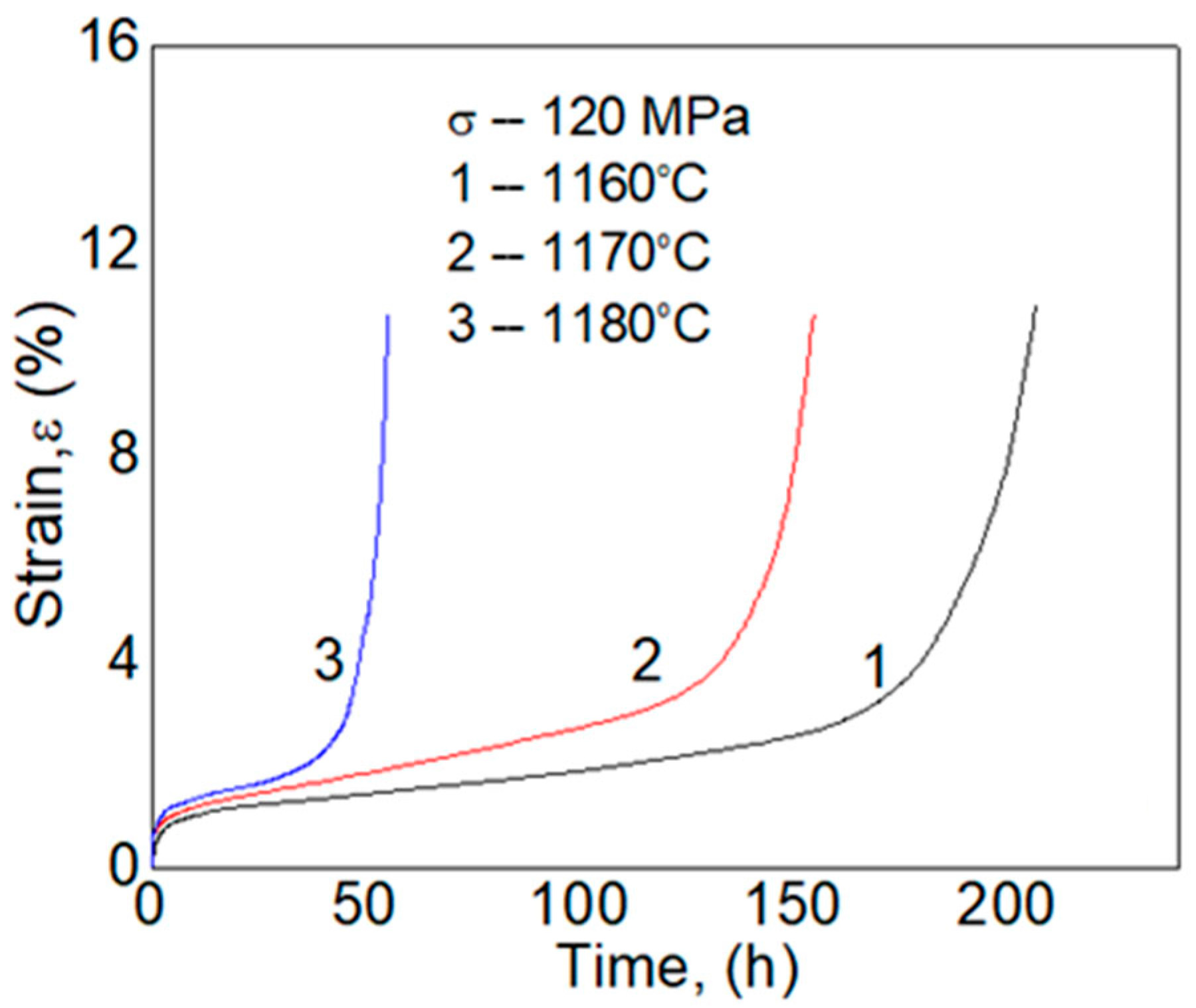
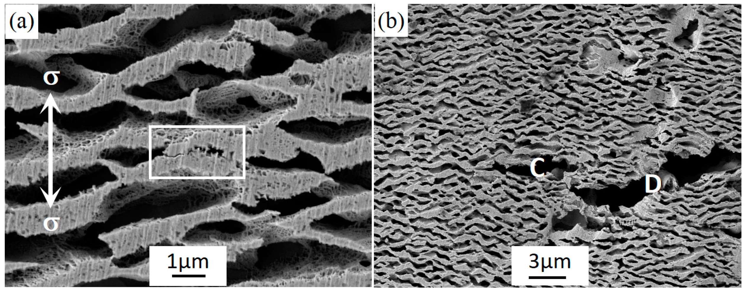
3.1. Microscopic Morphology and Creep Properties

The microstructure of the γ/γ′ two-phase system is shown in Figure 1. It can be observed that no TCP (topologically close-packed) phases precipitate from the γ matrix, and the morphology of adjacent γ phases appears uniform. Cubic γ′ strengthening phases are coherently embedded within the γ matrix along the [100] and [010] directions, as indicated by the arrows in the figure. The volume fraction of the γ phase is approximately 63%, and the dimensions of the γ/γ′ phases are measured to be 435 ± 15 nm and 95 ± 5 nm, respectively.
Figure 2 presents the X-ray diffraction (XRD) patterns of the alloy in the fully heat-treated condition. The peak separation of the γ/γ′ two phases at specific diffraction angles was performed using Origin 8.5 software. After the deconvolution of the composite diffraction peaks, the individual peaks corresponding to the γ and γ′ phases were extracted and positioned beneath the overall synthetic peak. The lattice constants of the γ and γ′ phases were calculated to be 0.3615 nm and 0.3600 nm, respectively, resulting in a lattice misfit of −0.3254%. Compared to alloys that do not contain Re or Ru, the lattice constant of the γ matrix phase in this alloy is relatively large. This is attributed to the enrichment of Re and Ru—both possessing large atomic radii—in the γ matrix phase [24].
The creep curves of the alloy at 120 MPa and temperatures of 1160 °C, 1170 °C, and 1180 °C are shown in Figure 3 [25]. During creep, dislocations exhibit different behaviors of multiplication and motion at various stages, leading to significant variations in the strain rate across different creep phases. According to the characteristics of the strain rate, the creep process can be divided into three distinct stages: the primary (initial) stage, the steady-state stage, and the tertiary (accelerated) stage [26]. The primary creep stage has the shortest duration but exhibits the highest strain rate. This is attributed to the immediate activation of a large number of dislocations in the γ matrix channels upon the application of external stress, resulting in a sharp increase in strain rate. As creep progresses, these dislocations accumulate at the γ/γ′ interface, forming an initial dislocation network (as illustrated in Figure 4). This network contributes to hardening and a rapidly decreasing the strain rate, thus shortening the duration of this stage. The steady-state stage is the longest phase within the creep process. During this period, thermal activation enables the continuous multiplication and motion of dislocations, leading to a gradual softening of the alloy. Simultaneously, the dislocation network evolves into a denser and more complete structure, enhancing resistance to dislocation motions. The dynamic balance between the softening and hardening mechanisms allows the alloy to maintain a relatively stable strain rate over an extended period.
The steady-state creep strain rates of the alloy at 120 MPa and temperatures of 1160 °C, 1170 °C, and 1180 °C gradually increase with temperature, measured as 0.0083%/h, 0.0176%/h, and 0.0219%/h, respectively. Correspondingly, the creep lifetimes are 206 h, 155 h, and 55 h. These results indicate a significant decrease in creep life when the temperature exceeds 1170 °C, suggesting that 1170 °C represents a critical threshold beyond which the mechanical properties of the alloy rapidly deteriorate.

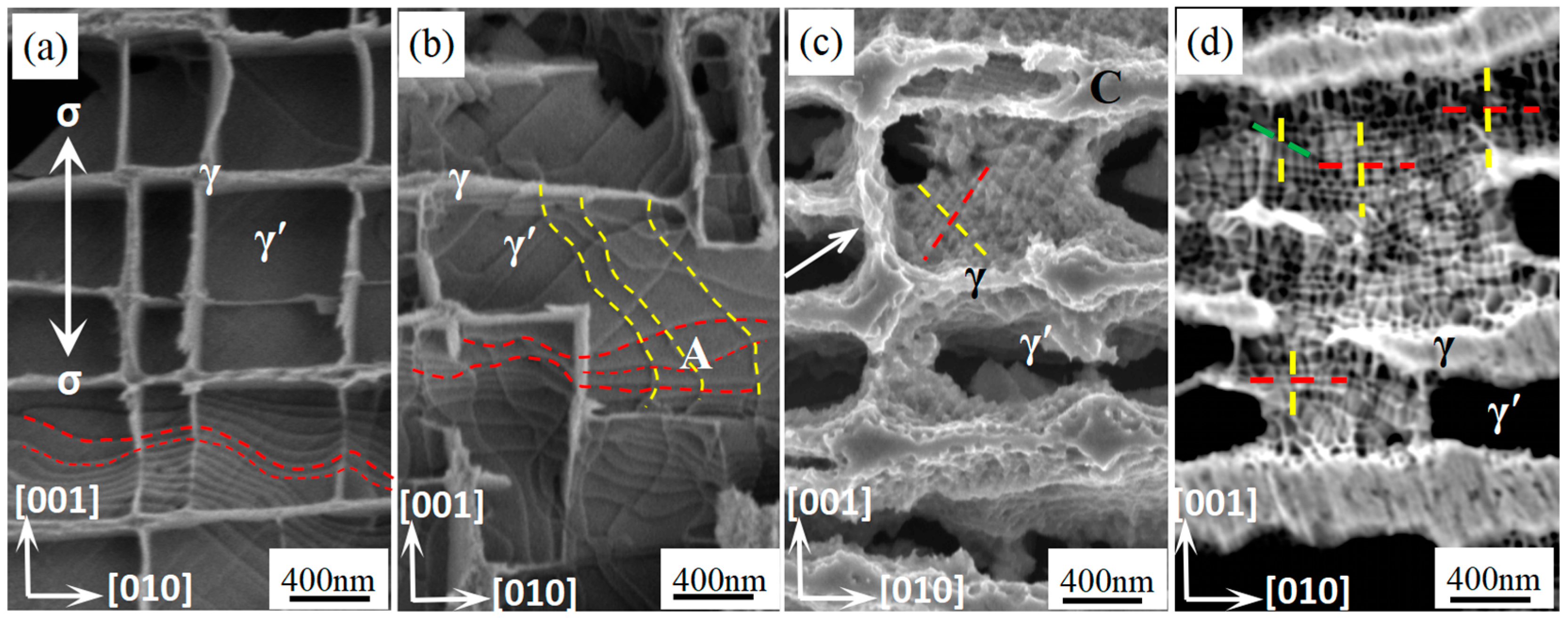
3.2. Microstructure Evolution

Figure 4 illustrates the formation process of the dislocation network at 1160 °C/120 MPa. Figure 4a shows the dislocation morphology within the γ matrix after 2 h of creep. At this stage, the γ′ phase remains cubic and has not yet evolved into a raft-like structure. A large number of <110>-type 60° mixed dislocations are observed in the vertical matrix channels, as indicated by the segments marked by the red lines. These dislocations are believed to originate from (111) edge dislocations through slip sweeping, a mechanism to be further analyzed in Section 4.1. Figure 4b presents the dislocation morphology after 2.5 h of creep at the same temperature and stress. The γ′ phase remains cubic, with no significant morphological changes. Meanwhile, <110>-type 60° mixed dislocations also appear in the horizontal γ matrix channels, marked by the segments indicated by the yellow lines. It is suggested that, in alloys with negative lattice mismatch under tensile stress, the vertical matrix channel experiences higher stress than the horizontal one, causing vertical dislocations to form earlier. When 60° mixed dislocations from both channels intersect, a dislocation mesh begins to form, as seen in region A of Figure 4b. At this stage, the mesh has a relatively large spacing, and although the dislocation network is initiated, the γ′ phase has not yet formed a raft-like structure. This suggests that the dislocation network at the γ/γ′ interface forms before the rafted γ′ phase.
As creep progresses, the morphology of the dislocation network evolves. Figure 4c shows the dislocation structure after 10 h of creep. Most horizontal channels have disappeared, with only a few remaining (indicated by arrows). The vertical channels have widened significantly, as shown in region C. Despite this, the γ′ phase still has not formed a complete raft-like structure. This extended rafting time is attributed to the presence of Re, which diffuses slowly and preferentially enriches the γ matrix near the γ/γ′ interface. This enrichment reduces elemental diffusion, hinders the coarsening of the γ′ phase, delays raft formation, and thus enhances microstructural stability. At this stage, dislocations form a more regular and denser <110>-type network, as shown by the red and yellow crossing segments in Figure 4c. Figure 4d displays the dislocation morphology after 30 h of creep. At this point, all horizontal matrix channels have disappeared, and the γ′ phase has fully rafted, while the vertical matrix channels have further widened. Dislocations now form either a <110>-<100> mixed dislocation network (yellow and green segments) or a <100>-type network (yellow and red segments), and the network spacing has decreased further. According to Zhang et al. [20], a well-formed and dense dislocation network effectively impedes dislocation movement, thereby improving the alloy’s mechanical properties.
Figure 5 shows the microstructure on the (100) plane after fracturing due to creep at 1160 °C/120 MPa for 206 h. The γ and γ′ phases are labeled accordingly in the figure. By examining the microstructure in different regions of the fracture surface, it is possible to deduce the creep damage evolution of the γ/γ′ two-phase system at various stages of the creep process. This approach allows for an assessment of how microstructural degradation develops over time, providing insights into the damage mechanisms and the stability of the γ/γ′ phases under prolonged high-temperature stress conditions.
The microstructural morphology of region A is shown in Figure 5b. Due to the relatively low stress in this region, the γ′ phase does not form a complete raft structure, and γ matrix channels remain parallel to the stress axis, as indicated by the arrow. The microstructures of sample areas B and C are shown in Figure 5c and Figure 5d, respectively. It can be observed that the γ′ phase has transformed into a raft structure, with its size remaining relatively unchanged at approximately 0.4 μm. The raft-like γ′ phase retains a relatively straight morphology, although the distortion of the γ′ phase in Figure 5d is slightly greater than that in Figure 5c. The γ/γ′ two-phase morphology in Figure 5d is more similar to that shown in Figure 4d. The microstructure of region D is shown in Figure 5e. In this region, the raft-like γ′ phase has undergone coarsening, with its size increasing to approximately 0.6 μm. The raft-like γ′ phase also exhibits a twisted morphology, with an angle of approximately 20° relative to the horizontal direction. The microstructure of region E is shown in Figure 5f, where the degree of coarsening and twisting in the rafted γ′ phase is significantly increased. Its thickness has grown to 0.7 μm, and the angle has increased to about 40°. Furthermore, part of the γ′ phase has transformed to have a large morphology, as indicated by the arrows in Figure 5f.
The TEM microstructure of the γ/γ′ two-phase system after creep at 120 MPa and 1160 °C for 120 h and 206 h is shown in Figure 6. The morphology after 120 h of creep is shown in Figure 6a. At this point, the two γ/γ′ phases are relatively smooth and have not undergone significant distortion. A large number of stacking faults are observed within the observed range, as indicated by the white box in the figure. The formation process of stacking faults is thought to proceed as follows: when dislocations in the γ matrix decompose at the γ/γ′ interface, a 1/3<121> leading partial dislocation is first decomposed and sheared into the γ′ phase, followed by a <211> trailing partial dislocation, with an SISF sandwiched between them, as shown in Equation (1).
< 1 ¯ 10 > 1 / 3 < 1 ¯ 2 1 ¯ > + S I S F + 1 / 3 < 2 ¯ 11 >
It is uncommon to observe stacking faults in the γ phase of nickel-based single-crystal alloys when they are subjected to creep conditions above 1100 °C. This phenomenon is attributed to two primary factors. First, a large number of insoluble elements, such as Re, Ru, and W, with large atomic radii, are enriched in the γ matrix phase. This enrichment results in a noticeable increase in the lattice constant of the γ phase, which in turn increases the mismatch between the γ/γ′ phases, thereby providing the driving force for the formation of stacking faults. Second, the addition of Re and Ru can reduce the stacking fault energy of the γ phase, making the formation of stacking faults more likely. Fleischmann et al. [27] have pointed out that reducing the stacking fault energy of an alloy can enhance its mechanical properties. The main reason for this is that alloys with a low stacking fault energy tend to generate stable stacking faults, which are less likely to decompose or move. As a result, the alloy exhibits a longer steady-state creep stage.
Figure 6b shows the microstructure and morphology of the γ/γ′ phases after creeping at 1160 °C/120 MPa for 206 h. It indicates that the rafted γ′ phase has undergone significant coarsening and twisting, and a large number of super-dislocations are observed within the γ′ phase. The super-dislocation traces, which cut into the γ′ phase, are oriented along the [011] and [011] directions at a 45° angle to the stress axis, as indicated in Figure 6b. The smooth rafted γ′ phase has also twisted and fractured at a 45° angle to the stress axis, as shown in regions E and F of the figure. It can be argued that, with the progression of creep time into the later stages, the strain in the alloy increases, leading to a higher dislocation density in the γ channels. As a result, a large number of dislocations accumulate near the dislocation network, generating substantial stress that damages the network. In the region where the dislocation network is disrupted, dislocations shear into the γ′ phase at a 45° angle to the applied stress. As creep continues, the activated dislocations undergo double-oriented slipping under maximum shear stress, causing fractures in the rafted γ′/γ two-phase structure. When (1/2)<110> super-dislocations are blocked during phase slip, they can cross slip onto another {111} plane, forming a dislocation cross-slip configuration with a 90° feature, as indicated by the short white arrows in Figure 6b.

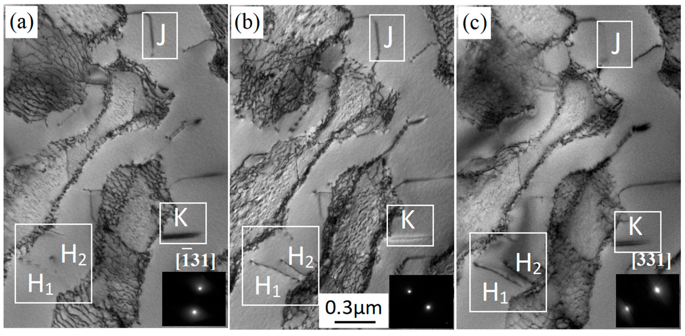
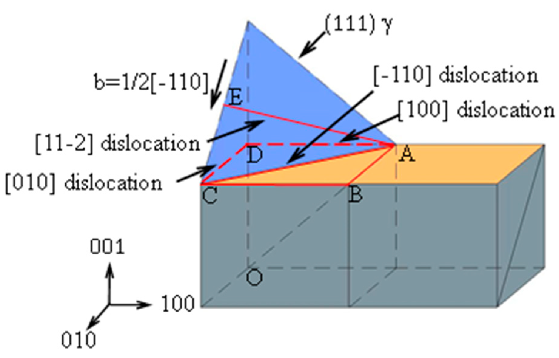
3.3. Dislocation Configuration at Different g-Vectors

Figure 7 shows the interfacial dislocation network after a fracture in the alloy at 1160 °C/120 MPa during 206 h of creep. As seen in Figure 7e, the dislocation interfacial network is composed of red lines in the [100] direction and green lines in the [010] direction. It can be observed that when the g-vectors vary, the same dislocation line appears in different states. The red dislocation line does not show contrast in conditions with g-vectors of [002] (Figure 7b) and [331] (Figure 7d), while it exhibits contrast in conditions with g-vectors of [1 3 ¯ 1] (Figure 7a) and [20 2 ¯ ] (Figure 7c). According to the invisible criteria g·b = 0 and g·b = ±(2/3) of dislocations, it is determined that the Burgers vector of red dislocation line is b = (1/2) [110]. The green dislocation line does not show contrast in the condition of g vector of [1 3 ¯ 1] (Figure 7a), while it exhibits contrast in the condition of the g vectors of [002] (Figure 7b) and [20 2 ¯ ] (Figure 7c) and [331] (Figure 7d), according to the invisible criteria g·b = 0 and g·b = ±(2/3) of dislocations, it is determined that the Burgers vector of the green dislocation line is b = (1/2) [101].
Bright field images of creep with a super dislocation configuration at 1160 °C/120 MPa for 206 h analyzed by TEM are shown in Figure 8. The dislocations in the γ′ phase are shown as H1, H2, J, and K in Figure 8. The images show that when the g-vectors are different, the same dislocation line shows different states.
It can be seen that the dislocation J displays contrast at g-vectors of [ 1 ¯ 31] (Figure 8a) and [022] (Figure 8b), while it does not show contrast at a g-vector of [331] (Figure 8c). According to the invisible criterion g·b = 0 dislocations, it is determined that the Burgers vector of J is bJ = (1/2) [1 1 ¯ 0]. Since the line vectors of the dislocation J are μJ = [110], the slipping planes of the dislocation J are J × μJ = (100). Dislocations K, H1, and H2 display contrast at a g vector of [331] (Figure 8c), while dislocations K, H1, and H2 do not show contrast and display contrast at a g vector of [022] (Figure 8b), respectively. While dislocations K, H1, and H2 display contrast and do not show contrast at a g vector of [ 1 ¯ 31] (Figure 8a), respectively. As such, we determined that the Burgers vector of k and dislocation H1 and H2 are bK = (1/2) [01 1 ¯ ] and bH = (1/2) [101], respectively. Since the line vectors of dislocations K and H1 and H2 are μK = [011] and μH = [211], respectively, the lipping planes of dislocation K is the bK × μK = (100) plane, and the slipping plane of dislocation H is the bH × μH = ( 1 ¯ 11) plane.
The above analysis indicates that the super dislocations cutting into the γ′ phase initially slip into the {111} plane. When these slipping super dislocations encounter larger atoms such as Re or Ru, they are impeded. Some of the super dislocations can cross slip to the {100} plane, forming K-W locks. K-W locks are considered immobile dislocations because dislocations require a significant activation energy to slip in the {100} plane, which increases the alloy’s creep resistance. The alloy retains a considerable amount of K-W locking after a creep fracture. This is a key factor contributing to the superior creep properties of this alloy compared to other alloys. A detailed analysis of this process will be provided in Section 4.2.

3.4. Creep Damage of Alloy

Figure 9 shows the process of crack initiation and propagation during the late creep stage at 1160 °C/120 MPa. The morphology of crack initiation after 160 h of creep is shown in Figure 9a. At this point, the alloy has just entered the third creep stage. Due to the rapid increase in strain, the number of dislocations in the γ matrix increases rapidly, forming dislocation entanglements. This results in damage to the interfacial dislocation network, preventing dislocations from climbing over the γ′ phase. Consequently, a large number of dislocations accumulate at the γ/γ′ interface, leading to stress concentration in regions with a high dislocation density. As creep progresses, the stress concentration continues to rise. Once the stress exceeds the bond strength between the γ/γ′ phases, the two phases begin to separate to relieve the stress, initiating microcracks at the γ′/γ interface, as indicated by the white box in Figure 9a. The initiation of these cracks effectively reduces the stress concentration, resulting in an increased strain rate as the alloy enters the third creep stage. This allows the alloy to creep smoothly at a higher strain rate.
As creep continues, more cracks initiate, and the alloy undergoes more pronounced necking. The effective stress increases steadily. When the angle of the crack tip reaches a critical value, the crack expands along the direction of maximum shear stress, forming larger cracks. The larger cracks observed after the creep fracture at 1160 °C/120 MPa are shown in Figure 9b. These cracks expand perpendicular to the stress axis under maximum shear stress and eventually connect (as labeled C and D in the figure). The formation of large cracks and their eventual coalescence lead to the creep fracture of the alloy, marking the final failure process during creep.

4. Discussion

4.1. Dislocation Network Transformation Processes

The generation and movement of dislocations are crucial for the plastic deformation of the alloy and the ultimate creep fracture. An interfacial dislocation network forms when dislocations from different slip systems meet at the γ/γ′ two-phase interface. This dislocation network can impede the motion of dislocations within the γ matrix and suppress the emission of dislocations from their sources. As a result, the dislocation network significantly contributes to the creep resistance of the alloy. It is important to note that the dislocation network is not static, as it transforms into creep. Different morphologies and densities of the dislocation network influence dislocation behavior in various ways, affecting the alloy’s creep properties accordingly [28,29].
The alloy generates mismatch dislocations under mismatch stress conditions during creep, which in turn forms a dislocation network. In this process the stress field due to the mismatch stress at the interface of the γ′/γ two phases is positive; therefore, only edge dislocations that also generate positive stresses can reduce the mismatch stress [30]. As an example, an edge dislocation with a Burgers vector of b = 1/2[110] and a dislocation line direction of [112] can be plotted with its motion path as shown in Figure 10. The dislocation will slip across the (111) plane of the γ phase until one end of it touches the (100) γ′/γ two-phase interface (position AE). As the slip is impeded, the dislocation moves in a sweeping slip manner in the (111) plane of the γ phase until its other end also hits the (100) γ′/γ two-phase interface (position AC). By sweeping across the plane, the edge dislocation becomes a <110> 60° mixed dislocation, and the edge component changes from b = 1 / 2 1 ¯ 10 to b = 1 / 2 1 ¯ 10 cos 30 . Although a sweeping slip will cause the edge dislocation component to be reduced, it will, at the same time, cause the edge dislocation to change from a point of contact with the (100) γ′/γ two-phase interface to a 60° mixed dislocation with a line of contact with the (100) γ′/γ two-phase interface, so a 60° mixed dislocation can more effectively reduce the mismatch of the alloy. When a large number of 60° mixed dislocations meet at the (100) γ′/γ two-phase interface, the <110> dislocation network is formed as shown in Figure 4a. After the dislocation sweeps and slides to AC to form a <110>-type 60° mixed dislocation, the <110>-direction AC dislocation can form an AB or AD <100>-direction dislocation around point A, or a CD or CB <100>-direction dislocation around point C, and a <100>-direction dislocation network is formed as shown in Figure 4b,c.
The mechanism behind the formation of the dislocation network involves the preferential creation of 60° mixed dislocations in the γ matrix, which occur along the <110> direction. These 60° mixed dislocations with different {111} slip surfaces meet at the γ/γ′ two-phase interface, forming a <110> dislocation network. As creep progresses, the 60° mixed dislocations in the <110> direction can transform into edge dislocations along the <100> direction, indicating that the dislocation network transitions to a <100>-type network. The intermediate state during this transformation corresponds to a hybrid <110><100> dislocation network. It is observed that the denser the dislocation network, the more effective it is at impeding dislocation motion and dislocation emission. In this alloy, a dense <110>-<100> hybrid dislocation network and a <100>-type dislocation network form during creep, as shown in Figure 4d. The analysis suggests that dislocation networks are formed and transformed to more effectively reduce the mismatch between the γ and γ′ phases. The degree of mismatch influences the type and density of the dislocation network. This alloy contains a high concentration of refractory elements (W, Re, and Ru), with both Re and Ru being segregated elements in the γ matrix. During ultra-high-temperature creep, the generation and movement of dislocations, along with the mutual diffusion of elements across the γ/γ′ two-phase boundary, occur simultaneously. Dislocations serve as fast channels for element diffusion, and these processes influence each other [31]. It is proposed that refractory atoms (W, Mo, Re, and Ru), which initially distribute throughout the γ matrix, are repelled along dislocation lines towards the γ′ phase interface at high temperatures and under applied loads. This causes a change in the lattice constant of the γ matrix phase at the γ/γ′ interface, increasing the mismatch stress. The increased mismatch between the γ and γ′ phases results in the formation of a complete <100>-type dislocation network at the γ/γ′ interface, contributing to the alloy’s superior creep resistance.

4.2. Analysis of Re/Ru for Improving Creep Resistance

Nickel-based high-temperature alloys consist of a γ-Ni matrix with a common-lattice interface and γ′-Ni3Al precipitation phase, both of which are face-centered cubic (FCC) structures. In the later stages of creep, as creep resistance decreases, a/2<110> dislocations moving into the γ matrix {111} plane can shear along the ruptured dislocation network into the γ′ phase and move into its {111} plane. With the creep proceeding as such, the dislocations can cross-slip to the {100} plane to form a K-W lock, which is shown by the J and K dislocations in Figure 8. K-W locks are called immobile dislocations because dislocations are more difficult to move and disintegrate because of their larger activation energy in the {100} plane. The presence of the K-W lock is an important reason for the better creep resistance of high-temperature alloys [32]. However, during the third stage of creep at higher temperatures, most of the K-W locks in single-crystal alloys can again cross slip into the {111} plane because of thermal activation, leading to a rapid decrease in creep resistance until creep fracture [33]. Therefore, whether K-W locks are generated and the temperature at which K-W locks can be kept during creep is a significant factor for the creep resistance of an alloy.
During creep, more and more Re and Ru and other heavy metal atoms are repelled to the γ/γ′ two-phase interface biased towards the γ′ phase and slowly form atomic clusters [34]. This can lead to enhanced interactions between the atoms, and the stronger interactions increase the resistance of the dislocations to slip in the {111} plane, forcing the dislocations to cross slip to the {100} plane, forming a K-W lock. In a single Re-containing alloy, under the action of high temperature loading during creep, Re is easily discharged from the γ′ phase into the γ matrix phase, leading to a rapid reduction in Re in the γ′ phase. This results in lower alloying in the γ′ phase and lower K-W activation energy, leading to re-activation of the K-W locks and cross slip to the {111} plane; this is the major reason for the lower retention temperature of the K-W locks in Re-only alloys. When Ru is added to Re-containing alloys, the Ru atoms entering the γ′ phase mainly occupy the position of Al. The Ru element can change the distribution behavior of Re between γ and γ′ phases, so that the Re and W elements that are polarized in the γ matrix are redistributed to the γ′ phase and attached to the vicinity of Ru, resulting in the “reverse distribution” effect [31]. This keeps the Re content in the γ′ phase constant during creep and improves the γ′ phase alloying. Therefore, the K-W lock dislocations of Re/Ru-containing alloys are difficult to reactivate. This is the main reason why more K-W locks are retained in the rafted γ′ phase in the near-fracture region after the present alloy is fractured by creep at 1160 °C/120 MPa for 206 h.

5. Conclusions

  • Stacking Faults in the γ′ Phase: The presence of stacking faults in the γ′ phase during the steady-state creep stage is a key factor contributing to the alloy’s excellent mechanical properties, even under ultra-high temperature conditions.
  • Re and Ru Content: The higher content of Re and Ru in the alloy enhances the driving force for dislocation motion, which promotes the formation of a dense dislocation network before the γ′ phase fully forms a raft-like structure. This dense dislocation network is a crucial factor in the alloy’s excellent mechanical properties during ultra-high-temperature creep.
  • Dislocation Network Formation: The process of dislocation network formation involves the dislocations at the γ/γ′ two-phase interface transforming into <110> 60° mixed dislocations that slip along the (100) plane. These 60° mixed dislocations, which sweep and slip on different {111} planes, meet at the (100)/two-phase interface, leading to the formation of a <110> dislocation network. As creep progresses, the 60° mixed dislocations can be transformed into edge dislocations along the <100> direction, transitioning the dislocation network to a <100>-type. The intermediate state of this transformation is a <110>-<100> mixed dislocation network.
  • Dislocation Shearing and K-W Lock Formation: In the late creep stage, a large number of dislocations shear into the γ′ phase. Some of these dislocations can cross slip to the {100} plane, forming a K-W lock. The high concentration of Ru in the γ′ phase enhances the alloying effect, preventing dislocations from cross slipping back to the {111} plane. This mechanism is a significant contributor to the alloy’s outstanding mechanical properties under ultra-high-temperature conditions.

Funding

We gratefully acknowledge the Guizhou Province Science and Technology Plan Project (QKHJC-ZK [2024] yiban604) (QKHJC-MS [2025] yiban008), Guizhou Science and Platform Talents (CXTD [2021]008), the Natural Science research project of the Education Department of Guizhou Province (qianjiaoji [2023]1100) for sponsoring this research.

Data Availability Statement

The original contributions presented in the study are included in the article, further inquiries can be directed to the author.

Acknowledgments

During the preparation of this manuscript/study, the author used ChatGPT 4.0 for the purposes of English writing improving. The author has reviewed and edited the output and take full responsibility for the content of this publication.

Conflicts of Interest

The author declares no conflict of interest.

References

  1. Tang, Y.T.; D’Souza, N.; Roebuck, B.; Karamched, P.; Panwisawas, C.; Collins, D.M. Ultra-high temperature deformation in a single crystal superalloy: Mesoscale process simulation and micromechanisms. Acta Mater. 2021, 203, 116468. [Google Scholar] [CrossRef]
  2. Yan, H.; Tian, S.; Zhao, G.; Tian, N.; Zhang, S. Creep and damage of a Re/Ru-containing single crystal nickel-based alloy at high temperature. Mater. Sci. Eng. A 2021, 808, 140870. [Google Scholar] [CrossRef]
  3. Yeh, A.C.; Tin, S. Effects of Ru and Re additions on the high temperature flow stresses of Ni-base single crystal superalloys. Scr. Mater. 2005, 52, 519–524. [Google Scholar] [CrossRef]
  4. Liu, S.H.; Liu, C.P.; Liu, W.Q.; Zhang, X.N.; Yan, P.; Wang, C.Y. Investigation of the elemental partitioning behaviour and site preference in ternary model nickel-based superalloys by atom probe tomography and first-principles calculations. Philos. Mag. Struct. Prop. Condens. Matter 2016, 96, 2204–2218. [Google Scholar] [CrossRef]
  5. Liang, X.; Wu, J.; Zhao, Y. Creep Fracture Mechanism of a Single Crystal Nickel Base Alloy Under High Temperature and Low Stress. Met. Mater. Int. 2022, 28, 841–847. [Google Scholar] [CrossRef]
  6. Latief, F.H.; Kakehi, K. Effects of Re content and crystallographic orientation on creep behavior of aluminized Ni-base single crystal superalloys. Mater. Des. 2013, 49, 485–492. [Google Scholar] [CrossRef]
  7. Wang, G.L.; Liu, J.L.; Liu, J.D.; Wang, X.G.; Zhou, Y.Z.; Sun, X.D.; Zhang, H.F.; Jin, T. Temperature dependence of tensile behavior and deformation microstructure of a Re-containing Ni-base single crystal superalloy. Mater. Des. 2017, 130, 131–139. [Google Scholar] [CrossRef]
  8. Wang, X.G.; Liu, J.L.; Jin, T.; Sun, X.F.; Hu, Z.Q.; Do, J.H.; Choi, B.G.; Kim, I.S.; Jo, C.Y. Dislocation motion during high-temperature low-stress creep in Ru-free and Ru-containing single-crystal superalloys. Mater. Des. 2015, 67, 543–551. [Google Scholar] [CrossRef]
  9. Heckl, A.; Neumeier, S.; Göken, M.; Singer, R.F. The effect of Re and Ru on γ/γ′ microstructure, γ-solid solution strengthening and creep strength in nickel-base superalloys. Mater. Sci. Eng. A 2011, 528, 3435–3444. [Google Scholar] [CrossRef]
  10. Vorontsov, V.A.; Kovarik, L.; Mills, M.J. High-resolution electron microscopy of dislocation ribbons in a CMSX-4 superalloy single crystal. Acta Mater. 2012, 60, 4866–4878. [Google Scholar] [CrossRef]
  11. Zhang, J.X.; Harada, H. Dislocation Configurations in Single-Crystal Superalloys during High-Temperature Low-Stress Creep. Adv. Mater. Res. 2011, 306, 433–437. [Google Scholar] [CrossRef]
  12. Zhang, J.X.; Murakumo, T.; Koizumi, Y.; Kobayashi, T.; Harada, H.; Masaki, S. Interfacial dislocation networks strengthening a fourth-generation single-crystal TMS-138 superalloy. Metall. Mater. Trans. A 2002, 33, 3741–3746. [Google Scholar] [CrossRef]
  13. Zhang, J.X.; Harada, H.; Koizumi, Y.; Kobayashi, T. Dislocation motion in the early stages of high-temperature low-stress creep in a single-crystal superalloy with a small lattice misfit. J. Mater. Sci. 2009, 45, 523–532. [Google Scholar] [CrossRef]
  14. Long, H.; Wei, H.; Liu, Y.; Mao, S.; Zhang, J.; Xiang, S.; Chen, Y.; Gui, W.; Li, Q.; Zhang, Z.; et al. Effect of lattice misfit on the evolution of the dislocation structure in Ni-based single crystal superalloys during thermal exposure. Acta Mater. 2016, 120, 95–107. [Google Scholar] [CrossRef]
  15. Long, H.; Mao, S.; Xiang, S.; Chen, Y.; Wei, H.; Zhou, Y.; Liu, J.; Liu, Y. A modification on Brooke formula in calculating the misfit of Ni-based superalloys. Mater. Des. 2017, 126, 12–17. [Google Scholar] [CrossRef]
  16. Zhang, J.; Wang, J.; Harada, H.; Koizumi, Y. The Effect of Lattice Misfit on the Dislocation Motion in Superalloys During High-Temperature Low-Stress Creep. Acta Mater. 2005, 53, 4623–4633. [Google Scholar] [CrossRef]
  17. Carroll, L.J.; Feng, Q.; Pollock, T.M. Interfacial Dislocation Networks and Creep in Directional Coarsened Ru-Containing Nickel-Base Single-Crystal Superalloys. Metall. Mater. Trans. A 2008, 39, 1290–1307. [Google Scholar] [CrossRef]
  18. Zhang, J.X.; Murakumo, T.; Harada, H.; Koizumi, Y.; Kobayashi, T. Creep Deformation Mechanisms in Some Modern Single-Cryatal Superalloys. Superalloys 2004, 2004, 189–195. [Google Scholar] [CrossRef]
  19. Huang, M.; Zhu, J. An overview of rhenium effect in single-crystal superalloys. Rare Met. 2016, 35, 127–139. [Google Scholar] [CrossRef]
  20. Tian, S.; Su, Y.; Qian, B.; Yu, X.; Liang, F.; Li, A. Creep Behavior of Single Crystal Nickel-Baesd Superalloy Containing 4.2% Re. Mater. Des. 2012, 37, 236–242. [Google Scholar] [CrossRef]
  21. Zhang, J.X. Strengthening by γ interfacial dislocation networks in TMS-162 toward a fifth-generation single-crystal superalloy. Metall. Mater. Trans. 2004, 35A, 1911–1913. [Google Scholar] [CrossRef]
  22. Bachurin, D.V.; Weygand, D.; Gumbsch, P. Dislocation-grain boundary interaction in <111> textured thin metal fflms. Acta Mater. 2010, 58, 5232–5241. [Google Scholar]
  23. Ma, S.; Carroll, L.; Pollock, T.M. Development of γ phase stacking faults during high temperature creep of Ru-containing single crystal superalloys. Acta Mater. 2007, 55, 5802–5812. [Google Scholar] [CrossRef]
  24. Tian, S.; Zhang, B.; Yu, H.; Tian, N.; Li, Q. Microstructure evolution and creep behaviors of a directionally solidified nickel-base alloy under long-life service condition. Mater. Sci. Eng. A 2016, 673, 391–399. [Google Scholar] [CrossRef]
  25. Tian, N.; Zhao, G.; Meng, T.; Tian, S.; Liu, L.; Yan, H.; Wang, G.; Jin, F. Ultra-high-temperature creep behavior of a single-crystal nickel-based superalloy containing 6%Re/5%Ru. Mater. Charact. 2021, 180, 111394. [Google Scholar]
  26. Caron, F.D. On the creep behavior at 1033K of new generation single-crystal superalloys. Mater. Sci. Eng. A 2004, 385, 245–257. [Google Scholar]
  27. Fleischmann, E.; Miller, M.K.; Affeldt, E.; Glatzel, U. Quantitative experimental determination of the solid solution hardening potential of rhenium, tungsten and molybdenum in single-crystal nickel-based superalloys. Acta Mater. 2015, 87, 350–356. [Google Scholar] [CrossRef]
  28. Wu, W.P.; Chen, B.; Shen, H.F.; Ding, Z.J. Molecular dynamics simulation of rhenium effects on creep behavior of Ni-based single crystal superalloys. Prog. Nat. Sci. Mater. Int. 2022, 32, 259–266. [Google Scholar] [CrossRef]
  29. Zhu, Y.; Li, Z.; Huang, M. Atomistic modeling of the interaction between matrix dislocation and interfacial misfit dislocation networks in Ni-based single crystal superalloy. Comput. Mater. Sci. 2013, 70, 178–186. [Google Scholar] [CrossRef]
  30. Hosford, W.F. Mechanical Behavior of Materials; Cambridge University: Cambridge, UK, 2005. [Google Scholar]
  31. Shu, D.; Tian, S.; Tian, N.; Liu, L.; Liang, S.; Zhang, B. Influence of Re/Ru on concentration distribution in the γ/γ′ phase of nickel-based single crystal superalloys. Mater. Des. 2017, 132, 197–207. [Google Scholar] [CrossRef]
  32. Asadi, E.; Zaeem, M.A.; Moitra, A.; Tschopp, M.A. Effect of vacancy defects on generalized stacking fault energy of fcc metals. J. Phys. Condens. Matter 2014, 26, 115404. [Google Scholar] [CrossRef] [PubMed]
  33. Mackay, R.A.; Gabb, T.P.; Nathal, M.V. Microstructure-sensitive creep models for nickelbase superalloy single crystals. Mater. Sci. Eng. A 2013, 582, 397–408. [Google Scholar] [CrossRef]
  34. Blavette, D.; Cadel, E.; Pareige, C.; Deconihout, B.; Caron, P. Caron. Phase Transformation and Segregation to Lattice Defects in Ni-Base Superalloys. Microsc. Microanal. 2007, 13, 464–483. [Google Scholar] [CrossRef] [PubMed]
Figure 1. SEM morphology of γ/γ′ two-phase.
Crystals 15 00370 g001
Figure 2. Composed and separated diffraction peaks on the (200) plane of the alloy after full heat treatment.
Crystals 15 00370 g002
Figure 3. Creep curves at 120 MPa.
Crystals 15 00370 g003
Figure 4. Dislocation network morphology of alloys creeping at 1160 °C/120 MPa for different periods. Images (ad) show morphology of alloys crept for 2 h, 2.5 h, 10 h, and 30 h, respectively.
Crystals 15 00370 g004
Figure 5. Microstructure of creep fracture specimen. (a) Schematic diagram of creep fracture sample; (bf) morphologies corresponding to A–E regions.
Crystals 15 00370 g005
Figure 6. Morphology of γ/γ′ phases after creeping at 120 MPa/1160 °C for different times.
Crystals 15 00370 g006
Figure 7. Dislocation network at different g-vectors after fracture at 1160 °C/120 MPa following creep for 206 h. (a) g = [1 3 ¯ 1], (b) g = [002], (c,e) g = [20 2 ¯ ], (d) g = [331].
Crystals 15 00370 g007
Figure 8. Dark-field images of super dislocation configurations taken with different g-vectors: (a) g = [−131], (b) g = [022], (c) g = [331].
Crystals 15 00370 g008
Figure 9. Creep fracture process under 1160 °C/120 MPa. (a) Creep for 160 h; (b) creep for 206 h.
Crystals 15 00370 g009
Figure 10. The dislocation line with a Burgers vector of b = 1/2 [ 1 ¯ 10] is the [11 2 ¯ ] edge dislocation motion path.
Crystals 15 00370 g010
Table 1. Composition of the alloys (mass, wt.%).
ElementAlTaCrCoMoWReRuNi
Chemical composition5.5--2.977.1--6.06560.75
Note: ‘--’ in the table indicates that it is not appropriate to disclose the content of the element.
Disclaimer/Publisher’s Note: The statements, opinions and data contained in all publications are solely those of the individual author(s) and contributor(s) and not of MDPI and/or the editor(s). MDPI and/or the editor(s) disclaim responsibility for any injury to people or property resulting from any ideas, methods, instructions or products referred to in the content.

