Review

Control of Intrinsic Defects in Lithium Niobate Single Crystal for Optoelectronic Applications

by
Rajeev Bhatt
1,2,
Indranil Bhaumik
1,2,
Sarveswaran Ganesamoorthy
2,3,
Riscob Bright
4,
Mohammad Soharab
1,2,
Ashwani Kumar Karnal
1,2,* and
Pradeep Kumar Gupta
1,2
1
Crystal Growth Laboratory, Laser Materials Section, Raja Ramanna Centre for Advanced Technology, Indore 452013, India
2
Homi Bhabha National Institute, Training School Complex, Anushakti Nagar, Mumbai 400094, India
3
X-ray Scattering and Crystal Growth Section, Condensed Matter Physics Division, Material Science Group, IGCAR, Kalpakkam 603102, India
4
TBM Division, Institute for Plasma Research, Bhat, Gandhinagar 382428, India
*
Author to whom correspondence should be addressed.
Crystals 2017, 7(2), 23; https://doi.org/10.3390/cryst7020023
Submission received: 9 December 2016 / Revised: 5 January 2017 / Accepted: 6 January 2017 / Published: 24 January 2017
(This article belongs to the Special Issue Crystal Growth for Optoelectronic and Piezoelectric Applications)

Abstract

:
A single crystal of lithium niobate is an important optoelectronic material. It can be grown from direct melt only in a lithium deficient non-stoichiometric form as its stoichiometric composition exhibits incongruent melting. As a result it contains a number of intrinsic point defects such as Li-vacancies, Nb antisites, oxygen vacancies, as well as different types of polarons and bipolarons. All these defects adversely influence its optical and ferroelectric properties and pose a deterrent to the effective use of this material. Hence, controlling the defects in lithium niobate has been an exciting topic of research and development over the years. In this article we discuss the different methods of controlling the intrinsic defects in lithium niobate and a comparison of the effect of these methods on the crystalline quality, stoichiometry, optical absorption in the UV-vis region, electronic band-gap, and refractive index.

1. Introduction

Lithium niobate (LiNbO3; LN) is a unique photonic material and often referred to as the silicon of photonics [1,2,3,4,5]. It has attracted a great deal of attention over the past three to four decades due to its favorable electro-optic, acousto-optics, non-linear optical properties, ease of fabrication, and robustness [1,2,3,4,5,6,7,8,9,10]. It has generated interest over the years mainly due to its use in nonlinear optical frequency conversion, electro-optical modulation, surface acoustic wave devices, holographic data storage, optical waveguides, and integrated optical applications [11,12,13,14]. In more recent times ferroelectric domain engineering of LN crystal has paved a new pathway for developing periodically poled LiNbO3 (PPLN) for fabricating optical parametric oscillators (OPO) to generate tunable lasers in the visible and mid-infrared radiation [11,15,16], tandem-poled lithium niobate crystals for the broadband green light source [17], laser projectors or display devices [18], and photonic band gap materials [19]. Further, there is a considerable interest in micro-structuring of LN crystals for their use in the micro-electro-mechanical system (MEMS) [20].
Lithium niobate in the stoichiometric composition melts incongruently whereas it melts congruently for a non-stoichiometric composition of 48.6 mol % Li2O and 51.4 mol % Nb2O5 [7,8,21]. Hence, a single crystal of LN can be grown by using conventional melt growth methods like the Czochralski (Cz) technique only from a melt with the aforesaid lithium deficient non-stoichiometric composition, unless a special growth procedure is adopted. Because of congruent melting at this non-stoichiometric composition (congruent LN; CLN) homogeneous and high optical quality CLN single crystals can be grown efficiently with a high conversion percentage of the initial melt (typically ~80%) without any composition variations along the length of the grown crystal [7,9]. Due to Li deficient composition and incongruent vaporization of Li2O, CLN crystals contain a high concentration of Li-vacancies (VLi) that favors the incorporation of unavoidable impurities, particularly transition metals that limits the performance or usability of devices fabricated from it [1,22].
Along with the Li-vacancies the excess Nb5+ ions present in CLN occupy vacant Li sites and form Nb-antisite defects (NbLi5+) [21]. Around 20% of the Li sites are partly occupied by Nb5+. Consequently to ensure charge neutrality a high concentration of Li vacancies is created in the lattice [21]. The presence of these defects and impurities adversely influence the nonlinear optical and ferroelectric properties of LN [21,22,23,24,25]. So, the performance of the devices made out of these crystals becomes limited. Therefore, controlling the defect structure is necessary to improve the properties and the efficacy of LN crystals.
There are several ways to control the defect in LN. One approach is to introduce impurities like Mg, Zn, and Zr into the lattice within a threshold concentration limit [9,10,26,27,28,29]. However, it should be noted that addition of these impurities (external defects) in the melt may give rise to additional growth problems such as composition inhomogeneities, introduction of sub-grain structures and boundaries, striation etc. in the crystals. The other methods to suppress the intrinsic defects are through direct growth of LN in near-stoichiometric composition by high temperature solution growth technique [9,30,31,32,33] or by converting a CLN wafer to near-stoichiometric form by the vapor transport equilibration (VTE) technique in a Li-rich ambience [34,35,36,37]. Although initially much of the attention was paid to growing CLN crystals from Li-deficient congruent melts, during the last two decades significant innovations in growth techniques have directed the research and development towards the growth of homogeneous near-stoichiometric LN (SLN) crystals. In this article the defect control in LN by different techniques and the effect of these preparation methods on the crystalline quality, stoichiometry, optical absorption, band-gap, and refractive index have been compared.

2. Defects in Lithium Niobate and Its Implications on the Optoelectronic Application

2.1. Point Defects in LiNbO3 Crystals

As mentioned in the introduction, along with the inherent thermodynamically generated vacant sites, non-stoichiometry related Frankel defects i.e., Li vacancies VLi−1 and Nb-antisites (NbLi5+) are the main defects in congruent LiNbO3 crystals [9,21,22,38]. Li vacancies are the result of Li deficiency in the composition. The Nb-antisite is generated as the excess Nb of the CLN composition occupies the Li sites. Non-stoichiometry in LiNbO3 arises due to the characteristic difference in its constitutional chemical bonds, i.e., Li–O and Nb–O bonds. The covalent Nb–O bonds are considerably stronger than the ionic Li–O bond [39,40]. Due to the dissimilar bond strength and nearly equal ionic radii of the Li and Nb ions, there is a natural tendency of the available extra Nb ions to occupy the Li sites creating an antisite defect. Consequently, due to the charge difference in the Li+ and Nb5+ ions, additional Li vacancies appear in the LiNbO3 lattice in order to maintain the charge neutrality [21].
Along with Li vacancies and Nb-antisites, there also exist oxygen vacancies (VO2+) and protons (H+) in the form of OH and OD complexes [7,8,9]. Being a transitional metal ion, Nb ions give rise to other defects such as free polaron (NbNb4+), bound polaron (NbLi4+), and bi-polarons (NbLi4+–NbLi4+) by trapping electrons [41]. Similarly, Li-vacancies also form hole-polarons by trapping holes [41]. So, the departure from stoichiometry leads to a high degree of structural disorder and point defects in LN crystals [9,20].
In the literature there are three different models based on Li vacancies [38], Nb vacancies [42], and oxygen vacancies [43] explaining the defect structure of LN. However, the most accepted model, explaining most of the properties of LN, is represented by the Li-site vacancy (V) model: [Li1−5x(NbLi)xV4x][Nb][O3] proposed by Larner et al. [38]. According to this model the structure remains stable up to x = ~0.02 and the congruent melting is for x = 0.018. Figure 1 shows a representative model for the defect structure of CLN [20].

2.2. Effect of Intrinsic Defect on Properties

It is well known that optical properties of a material are sensitive to the intrinsic defects and impurities. The NbLi5+/4+ defects act as electron trap sites and form polaron (NbLi4+) and bipolaron (NbLi4+–NbLi4+) states which are responsible for the photorefractive damage [1,44]. The presence of these defects and impurities leads to light-induced changes in the refractive index that results in the optical distortion [1], phase modulation [22], Bragg scattering [23], and green induced infrared absorption (GIIRA) [45], and consequently decreases the efficiency of nonlinear interactions when the crystal is subjected to an intense visible radiation [22,23]. Because of these defects the value of the optical properties such as non-linear optical coefficient, linear electo-optic coefficient etc. (Table 1) is low in defect rich CLN crystal.
However, these light induced optical effects in CLN can be minimized to a significant extent by operating the device at higher temperature (~180 °C) or by using defect controlled stoichiometric LN having lesser intrinsic defects and impurities [23]. When grown in the near-stoichiometric form (nSLN, Li/Nb ~ 1) the optical properties improve significantly (Table 1) as a result of the decrease in the defect concentration [30,46,47,48,49,50,51,52]. So nSLN is a better choice for nonlinear frequency conversion, as well as photo-refractive and holographic data storage applications [53,54] in comparison to CLN.
Further the intrinsic defects influence the dielectric and ferroelectric properties of CLN [24,25,54,55]. The NbLi5+ antisite defects in CLN act as pinning centers that inhibit the movement of the ferroelectric domain wall in the crystal [9]. Hence, CLN crystals exhibit a high ferroelectric switching field ~21 kV/mm (Table 1) that limits its use for domain engineered devices [49,56]. As the defect concentration is reduced in nSLN the coercive field becomes less than 4 kV/mm [52,53]. Even a coercive field as low as 200 V/mm has been reported for nSLN crystal grown from K2O flux [49]. SLN crystals, therefore, offer favorable properties for the realization of periodically poled devices (PPLN) [54] and domain engineering [52,53] where an electric field has to be applied for poling the material.
Being a ferroelectric material lithium niobate [57] undergoes a structural phase transition from a ferroelectric phase (R3c) to a paraelectric phase ( R 3 ¯ c ) at around 1140 °C. The ferroelectric-to-paraelectric phase transition temperature of LN occurs at different temperatures depending upon the Li/Nb ratio in the crystal [58,59]. It varies from 1140–1200 °C for Li deficient LN to near stoichiometric LN. A strong correlation between the composition and the Curie temperature is established by the O’Bryan equation [60].

3. Preparation of Defect Controlled Crystals

Control of defect in LN has been reported by various methods such as incorporation of certain impurities (Mg2+, Zn2+, Zr4+, Hf4+ etc.) into the lattice within a threshold concentration limit [61,62,63,64,65,66,67,68,69], direct growth of LN in near-stoichiometric composition by high temperature solution growth (HTSG) technique [30,31,32,47,48] or conversion of a congruent LN (CLN) wafer to a near-stoichiometric form by vapor transport equilibration (VTE) in Li-rich ambience [34,35,36,37]. The details of the methods are discussed below.

3.1. Defect Control through Doping

The incorporation of divalent impurities like Mg2+, Zn2+ etc. into the lattice within a threshold concentration limit reduces the intrinsic defects of the CLN crystals and consequently the damage threshold increases [9,10,26,27,28,29,52,61,62,63]. At the same time, some optical properties such as refractive index, electro-optic coefficients, nonlinear optical coefficients, and phase-matching conditions for various configurations of second-harmonic generation (SHG) are influenced by these dopants [18,19]. In the present article Mg has been taken as an example in this context.
In CLN, because of the excess Nb5+ present at Li1+ sites (i.e., NbLi5+) four additional Li vacancies (VLi−1) are created for charge compensation. Up to a threshold concentration, the Mg2+ ions preferentially replace the excess Nb at Li sites. As Mg2+ has a lower valence state than Nb5+ ion, the number of Li-vacancies created due to charge compensation reduces [52,61,62]. In the case of CLN the threshold concentration of Mg is ~4.5 to 5 mol %, beyond which it starts substituting the regular Li site leading to a decrease in the Li/Nb ratio [61]. Zhong et al. [27] showed that the resistance to photo-refractive (optical) damage improves a hundred-fold on doping CLN with 4.6 mol % Mg.
Undoped and Mg doped CLN single crystals were grown from congruent melt using the Czochralski (Cz) technique. The starting material was prepared from 99.998% Li2CO3 and 99.999% Nb2O5 taken in the congruent ratio. A multi-step synthesis route was adopted as described in ref. [70]. An indigenously developed automatic diameter controlling software was used to grow crystals with uniform diameter. Seeding was done using a (00.1) oriented seed as per the procedure describe in ref. [71]. The rotation rate was kept at 25 rpm during seeding, and then gradually reduced to 15 rpm during the growth of the constant diameter body part to obtain good quality crystals. The crystals were pulled at a rate of 2–4 mm/h. Following this methodology high quality single crystals of undoped CLN (for comparison), and 2.0 and 4.0 mol % Mg doped CLN were grown. However, the growth of crystals with 6 mol % Mg using the same growth conditions resulted in cracking due to excess strain because of the higher concentration of Mg. However, a low pulling rate of 1 mm/h and slow post-growth cooling of 50 °C/h led to crack-free 6 mol % Mg-doped crystals [70]. The typical sizes of the grown crystals were ~25 mm in diameter and 30–40 mm in length (Figure 2).

3.2. Defect Control by Growing Near Stoichiometric LN Crystal

Near stoichiometric LN (nSLN) crystals were grown from high temperature solution by the top seeded solution growth (TSSG) technique from two different solutions, namely (a) Li-rich solution (58.0 mol % of Li2O and 42.0 mol % of Nb2O5) [2] and (b) SLN with K2O solvent (K2O/LiNbO3 ~0.16–0.17, molar ratio) [28]. The chemical was synthesized as per the procedure reported in ref. [70]. The axial temperature gradient of the furnace used was ~10 °C/cm. In order to quickly establish the saturation temperature with minimum loss of seed during the seeding procedure the growth was initiated with a c-oriented seed using a seeding technique described in ref. [71]. The large difference in the composition of the Li-rich melt and the growing crystal (nSLN_L) posed problems [9,30,47] such as striation, faceting, and core formation which were avoided by optimizing the growth parameters and by improving the temperature stability of the growth furnace. The pulling and rotation rate were adjusted during the growth to avoid core and inclusions in the grown crystals. The optimized growth parameters for the growth of nearly flat interfaced, inclusion- and crack-free single crystals are: 0.2–0.5 mm/h pulling, 2–20 rpm rotation and 0.04–0.1 °C/h cooling rate for the thermal gradient as mentioned above. Figure 3a shows crystals grown from Li-rich melt (nSLN_L). The sizes of the grown crystals were up to 15–20 mm in diameter and 30–50 mm in length. To avoid composition variation which arises due to a gradual increase in the Li content in the remaining melt during the growth process, crystals with weight less than 5% of the total starting melt were pulled. A nearly flat solid-liquid interface was ensured in order to have a high quality crystal [72] as a non-flat interface leads to highly strained regions near the core of the crystal and results in the generation of extended defects like dislocations, low-angle grain boundaries, cracks etc. in the crystal [72].
Similarly, nSLN crystals (nSLN_K) were also grown using K2O as solvent with similar growth conditions and parameters except for the rotation rates, which were marginally higher (20–5 rpm) in this case (Figure 3b).

3.3. Preparation of Near Stoichiometric Sample by VTE

For enriching the Li content in the grown CLN crystal the vapor transport equilibration (VTE) process was employed. In this method a c-oriented CLN wafer of thickness ~1 mm was hung inside a platinum crucible containing 300 g mixture of pre-reacted lithium-rich Li3NbO4 and LiNbO3 powder [73,74]. The crucible was tightly covered with a platinum foil and heated at 1100 °C for 100 h.

3.4. Test of Optical Homogeneity

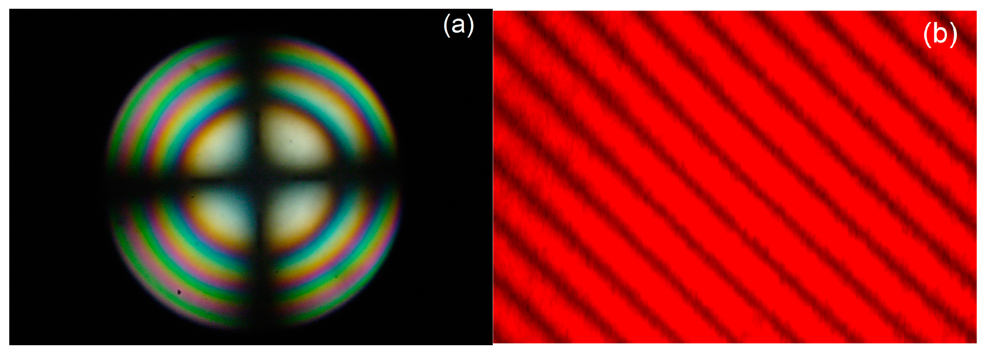
Optical homogeneity of the samples was investigated by concoscopy and orthoscopic birefringence interferometry [75]. The conoscopy patterns of c-plates observed under a polarized light optical microscope (Olympus BX60, Olympus Corporation, Tokyo, Japan) consisted of well-shaped circular rings for all the samples confirming the homogeneity of the samples along the radial direction. Further, the orthoscopy of y-cut samples was carried out to check the homogeneity of the samples along the growth (axial) direction. The setup is comprised of a He-Ne laser, beam expander, polarizers, and a CCD camera. The collimated parallel beam travels through birefringent crystal (y-cut, dimension: 10 × 10 × 1 mm3) placed between cross polarizers with one polarizer placed at 45° with respect to the z-axis of the sample. The phase delay between the ordinary and extraordinary components of the light passes through the sample and polarizers resulting in the formation of interference fringes revealing the birefringence map of the sample. The corresponding phase delay is:
φ = 2πΔn·d/λ
where λ is the wavelength of the laser, d is the sample thickness, and Δn = neno is the birefringence. The birefringence fringe pattern is characterized by nearly straight-line fringes corresponding to contour maps of equal birefringence for all the samples. The nearly straight line fringes and their nearly equal spacing signify the good optical homogeneity of the grown crystals along the growth direction. The order of optical homogeneity was estimated by calculating the per fringe variation in δn), which is given as:
δ ( Δ n ) λ / d 5.2 × 10 4
The estimated optical homogeneity of the all the samples was better than 10−5/mm. Figure 4 shows representative conoscopy and birefringence fringe patterns for a Mg:CLN crystal.

4. Effect of Defect Control Processes on Crystalline Quality

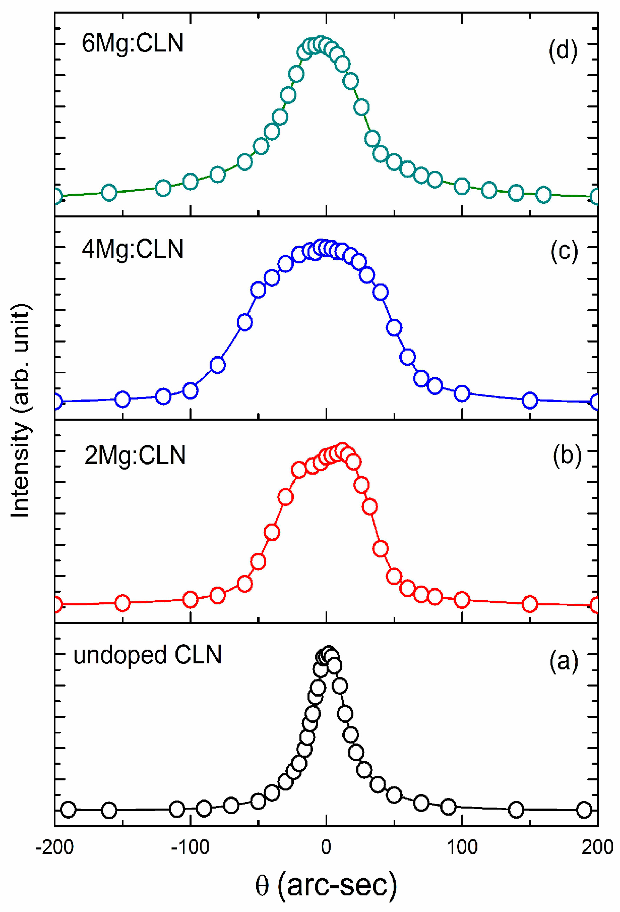
The effect of the defect control on the structural defects and disorder of samples prepared from the crystals grown by Mg doping (Mg:CLN), nSLNs, and VTE treated CLN was analyzed by high resolution X-ray diffraction (HRXRD) measurements for (00.6) diffracting plane in symmetrical Bragg geometry with Mo-Kα1 radiation. Figure 5a–d shows the diffraction curves (DC) of undoped CLN (for comparison) and Mg-doped (2.0, 4.0, and 6.0 mol %) LN crystals. Figure 6a–c shows DCs for nSLN_L and nSLN_K crystals prepared by HTSG, and nSLN_V prepared by the VTE method.
The DCs of the Mg-doped LN (Figure 5b–d) crystals contain a single diffraction peak. The full-width at half-maximum (FWHM) of the DCs estimated using curve fitting are 76, 112, and 65 arc-sec for 2.0, 4.0, and 6.0 mol % Mg doped samples respectively. Overall the FWHMs of Mg:CLN are higher than the CLN sample signifying the presence of relatively more point defects in Mg doped samples. In comparison to CLN, although it has lower Li vacancy and anti-site defect, the divalent Mg ions create a distortion in the lattice around themselves as the ionic radii of Mg2+ (86 pm in octahedral coordination) is more than Nb5+ (78 pm in octahedral coordination). As a result the FWHM in the DC is more than that of CLN.
Further, the FWHM increases as the Mg doping was increased in the 2 and 4 mol % samples (2Mg:CLN and 4Mg:CLN) due to an increase in the lattice distortion with the increase in Mg concentration. However, the lower FWHM (Table 2) in the 6 mol % doped crystal is due to the lower pulling rate, employed to grow this composition without cracks, as pulling rate influences the crystalline perfection. In fact the cracking of the 6 mol % Mg doped crystal (6Mg:CLN) when grown with the pulling rate the same as that used for other compositions (2Mg:CLN and 4Mg:CLN) implies the presence of a relatively higher strain in that particular sample.
The DCs of CLN (Figure 5a) and nSLN_L (Figure 6a) consist of a single diffraction peak that signifies that these crystals are free from any internal sub-grain boundary [76,77,78], which is otherwise usually observed because of the strain generated during the post-growth cooling due to structural phase transformation at ~1140 °C (paraelectric to ferroelectric), growth imperfections, and instabilities. The FWHM of the DCs was evaluated by Lorentz fitting as tabulated in Table 2. Although the samples are devoid of any grain boundary, on close examination an asymmetry in the right wing of the DCs was observed in nSLN_L which may be attributed to the presence of point defects and their agglomerates in the sample causing strain in the lattice around the defect core that leads to defuse scattering.
On the other hand, the DCs for nSLN_V (Figure 6b) and nSLN_K (Figure 6c) are characterized by superimposition of a number of peaks signifying the presence of point defects as well as low angle grain boundaries. The peak fitting revealed that the DC of nSLN_V consists of three additional peaks. The two well separated peaks on the right of the main peak correspond to low angle grain boundaries formed due to the employed thermal treatment. The FWHM of the main peak is ~45 arc-sec.
The DC for SLN_K (Figure 6c) is the widest and consists of several satellite peaks along with the main peak as seen in curve fitting. The fitting shows the presence of low angle grain boundaries with a tilt angle in the range of 57–196 arc-sec. The broad and multi-peak DC of the nSLN_K sample depicts a relatively poor crystalline perfection with respect to other nSLN samples [79].
From the observations of the HRXRD measurements one can conclude that the structural quality of CLN is relatively better than all the three nSLN and the Mg:CLN samples. This may be due to the fact that although nSLN samples are better than CLN in terms of stoichiometry (as seen from the optical measurements described below) with lesser point defects, the higher dimensional defects like dislocation loops and low angle grain boundaries are more in the nSLN samples. It is noteworthy that nSLN crystals grown from K2O solution (nSLN_K) or Li-rich solution (nSLN_L) may contain several growth imperfections that arise during the growth process as the occurrence of constitutional super-cooling is common in such growth methods having additional or excess ions [80]. Further, the temperature fluctuation at the solid-liquid interface during the growth influences the growth rate which subsequently deteriorates the structural quality of the growing crystal. Also, nSLN_L and nSLN_K have similar or more FWHM in comparison to Mg:CLN because of the growth issues related to them. The vapor transport equilibration treated CLN sample, i.e., SLN_V, has similar FWHM to pristine CLN with an asymmetry in the right wing of the DC but lesser FWHM than the nSLN_L and nSLN_K. This suggests that the overall crystalline quality is almost unaffected in VTE though a few low angle grain boundaries appeared due to the involved thermal treatment and the diffusion process.

5. Effect of Defect Control Processes on the Optical Absorption

The optical band-gap and the defect related absorption was investigated by optical transmission measurements carried out using a Jasco V670 spectrophotometer (JASCO International Co., Ltd., Tokyo, Japan). The absorption coefficient (α) was calculated from the transmittance spectra using the relation [81]:
T ( 1 R ) 2 exp ( α d )
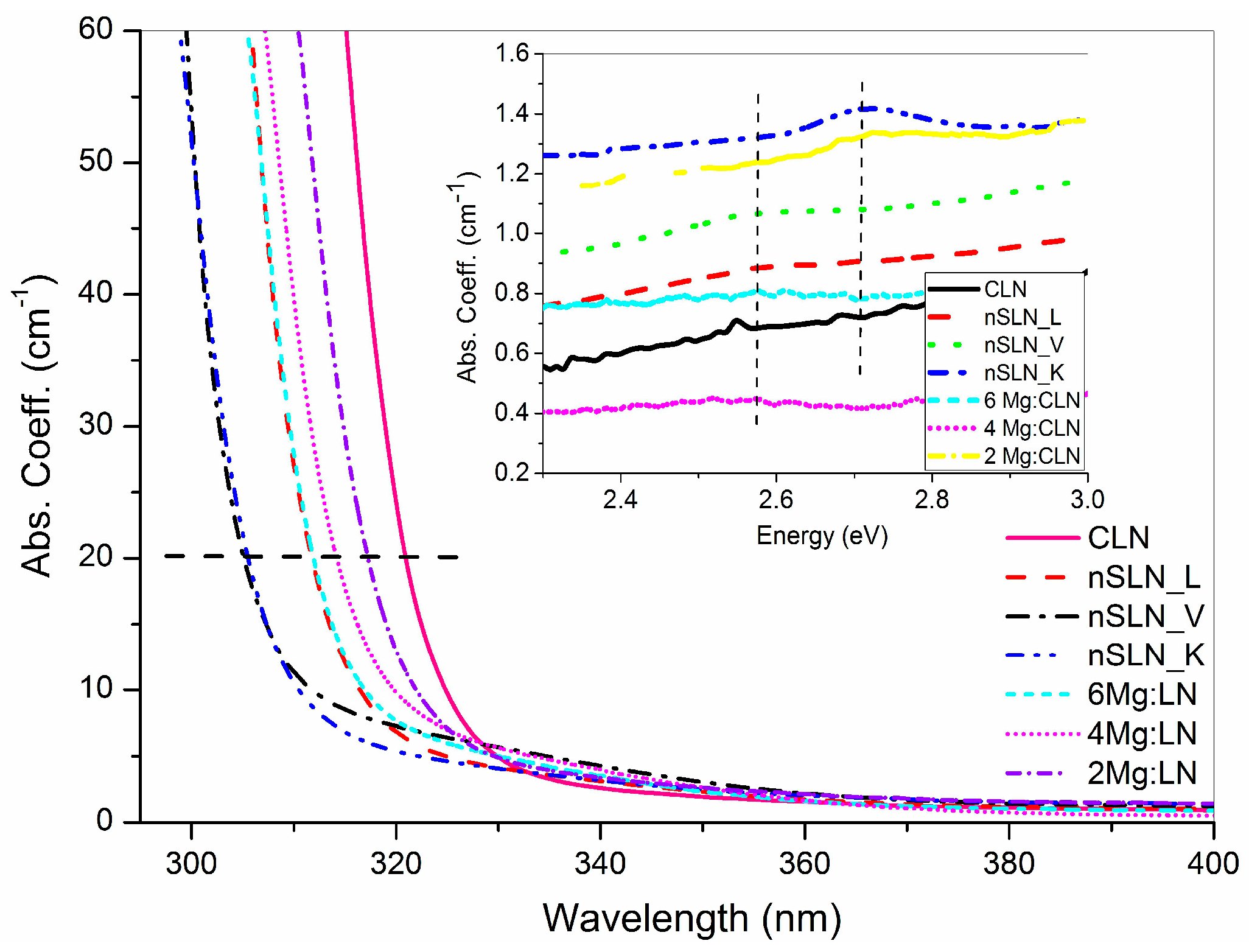
where T is transmittance, R is reflectivity, and d is the sample thickness. Figure 7 shows the absorption spectra of nSLN crystals prepared by different techniques, i.e., nSLN_L, nSLN_K, nSLN_V and the Mg (2, 4, and 6 mol %):CLN crystals along with the spectrum of undoped CLN included for comparison. The absorption spectra are characterized by the fundamental absorption edge (AE) which in LN arises due to the inter-band electronic transition between the 2p orbitals of the O2 (valance band) and the 4d orbitals of the Nb5+ (conduction band) [82]. The AE was estimated as the wavelength at which the absorption coefficient is 20 cm−1 [83] and summarized in Table 2. A blue shift in the fundamental absorption edge of nSLN and Mg doped samples with respect to CLN sample is evident from the plot. The blue shift indicates the influence of intrinsic defects on the fundamental absorption processes and signifies an improvement in the optical band structure and the lattice of LN due to a decrease in intrinsic defects (NbLi+5 and VLi−1) and defect-induced band tailing states that give rise to band narrowing [84]. The disorder in the Nb sub-lattice due to the presence of NbLi5+ antisite defects leads to the distortion in the oxygen octahedron and influences the fundamental AE.
Further, there is a strong correlation between the AE and the Li/Nb ratio in the grown crystal [83] which was used to estimate the Li content in the grown crystals. A shift in AE towards the lower wavelength in comparison to the CLN was observed for all the nSLN samples (Figure 7). This confirms a decrease in the intrinsic defects and an increase in stoichiometry (i.e., Li/Nb) samples which was estimated using the following empirical relation [83]:
E   ~   4.112 0.189 50 c L i
where E (eV) is the photon energy corresponding to the AE and cLi is the Li2O content in the sample in mol %. The values of the AE and the corresponding Li/Nb ratio for all the nSLN crystals are summarized in Table 2. The AE for nSLN_L (310.2 nm) is better than the value reported by Wang et al. i.e., 311 nm for the nSLN_L sample [85]. Further the observed AE for nSLN_K (305.5 nm) grown from K/Nb~0.32 is 305.5 nm. On comparison with the values available in the literature it was found to be in close agreement with the reported values of 305.5 nm [86] and 306 nm [87,88]. Although, there is a report of AE ~303.2 nm for nSLN_K grown from K/Nb ≥ 0.38 and Li/Nb = 1 [86], but this composition leads to a growth of inhomogeneous crystals [84]. According to Peter et al. [84], growth from a K/Nb ratio more than 0.36 and Li/Nb = 1 results in crystals with a bottom portion having multi-phase.
The AE was found to be ~304.6 nm for the sample prepared by the VTE technique (nSLN_V). This value is slightly blue shifted compared to the AE ~305 nm reported by Chen et al. [89] for VTE treated sample. Comparison of the AEs of the samples prepared in the present investigation revealed that the AE is the lowest for nSLN prepared by VTE (nSLN_V). This implies that the VTE technique is the most effective technique for preparing nSLN (particularly for a sample in the form of a thin wafer) in comparison to the other methods. The CLN crystal used for VTE in general contains ~4% Li vacancy and 1% Nb antisites [90]. Annealing of this wafer in Li-rich ambient reduces the Li-vacancies to a great extent by replacing Nb-antisites with regular Li ions via solid-state diffusion at elevated temperature and brings the composition close to the phase boundary limit i.e., 49.9 mol % Li2O [91].
Further, the measured AEs for the Mg:CLN samples are 317.1 nm (2 mol %), 314.2 nm (4 mol %), and 311.6 nm (6 mol %) in comparison to the AE ~320.6 nm for undoped CLN. The observed blue shift in the UV absorption edge is in agreement with the reported literature [85,86,87]. The gradual blue shift confirmed the reduction of the lithium vacancy (VLi) in the grown crystals with the concentration of Mg in the lattice as discussed earlier. However, in comparison to the other processes employed in this investigation the effect of Mg doping on the improvement of stoichiometry is the least (Table 2).
The effect of Mg doping can be represented by Larner’s Li-site defect model [38]: [ L i 1 5 x + 3 y ( M g N b L i ) y ( N b L i ) x y V 4 x 3 y ] [ N b ] O 3 . The reduction in the number of Nb antisites on Mg doping leads to a reduction in the number of localized excitons or other band-tail states that consequently results in a blue shift in the AE.
The influence of the preparation methods on the electronic band-gap of LN was investigated from the absorption spectra using the Tauc relation [81]:
α h v A ( h v E g ) n
where, A is a constant, is photon energy, Eg is the allowed energy gap, and n is an exponent determined by the nature of the electron transition during the absorption process. The value of n is ½ for the allowed direct transition and 2 for the allowed indirect transition. As LN is an indirect band gap material [92,93], the optical band gap characterized by phonon mediated allowed indirect transitions near the fundamental AE in the absorption spectra is estimated using the relation [81]:
α h v { A ( h v E g i n d + h Ω ) 2   for   h ν E g i n d + h Ω 0 otherwise
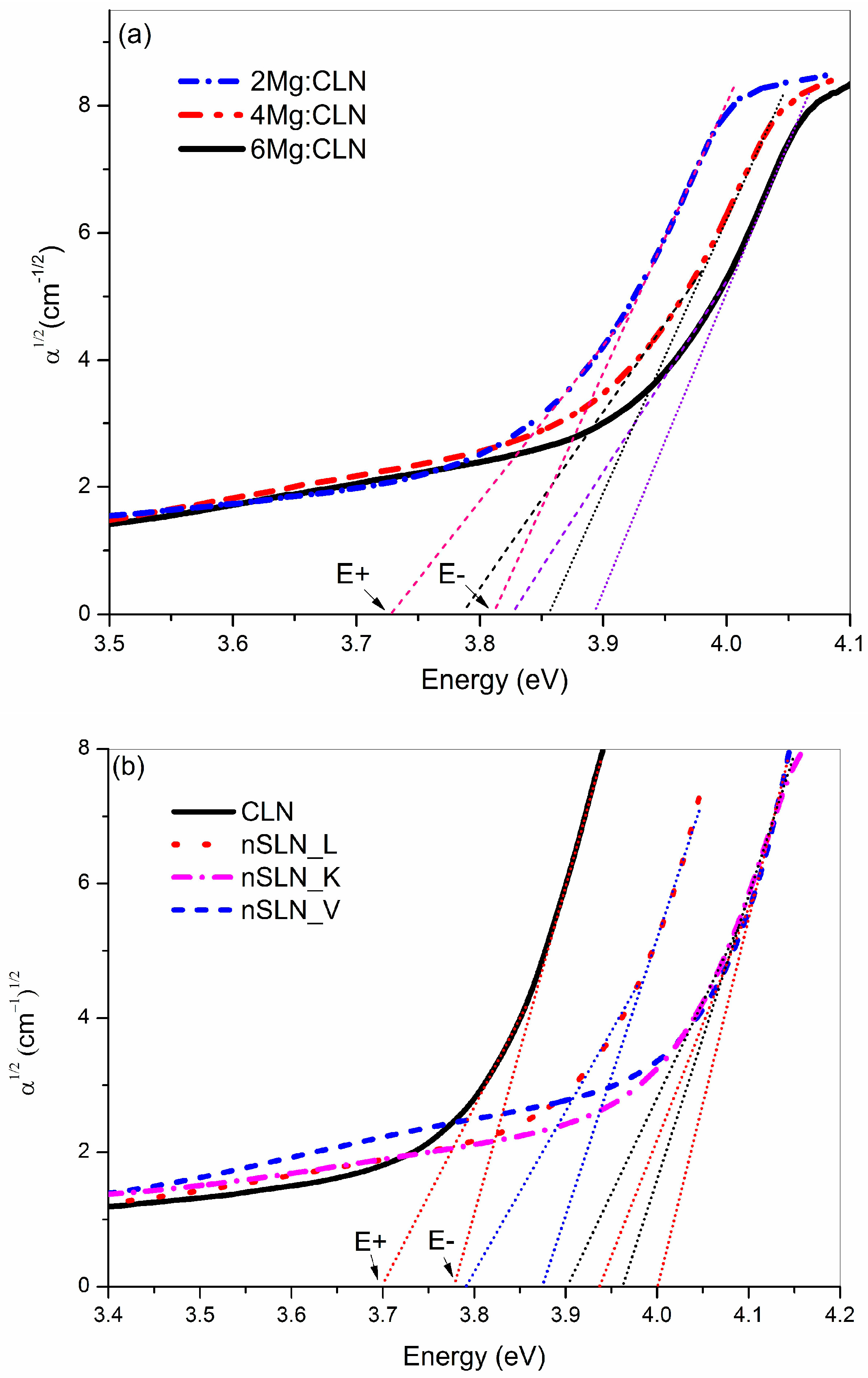
where, E g i n d is the indirect bandgap energy and hΩ is the energy of the absorbed (+) or emitted (−) phonons needed to conserve the momentum. For estimation of the indirect band-gap energy values of (α)1/2 vs. are plotted in Figure 8a,b for all the nSLN and Mg:CLN samples (undoped CLN is included for comparison). The two adjoining linear segments near the band edge describe the phonon assisted fundamental photon absorption process corresponding to the absorption or emission of phonons. The linear fits of the absorption data and their respective intercept values E and E+ with the energy axis at α = 0 were used to estimate the indirect band-gap and the associated phonon energy using Equation (6). The estimated values are summarized in Table 2.
The energy of phonons involved in the inter-band transition is in the range of 30–40 meV (241–322 cm−1), which is associated with the E(TO2)–E(TO6) or A1(TO1)–A1(TO2) modes of Li/O and Nb/O vibrations as per the Raman spectra reported in reference [94]. Moreover, it is clear from the table that the indirect band-gap energy of Mg:CLN and the solution grown/VTE prepared nSLN has increased significantly in comparison to CLN. This certainly indicates a decrease in the concentration of intrinsic defects and trace impurities at the Li sites resulting in a decrease in the band tailing or band narrowing phenomena in the crystals grown by the respective growth methods. The observed increase in band gap energy for Mg doped and nSLN samples confirms a decrease in structural and lattice defects (Li vacancies and NbLi5+ defects). This leads to an increase in the photoconductivity and a decrease in the light induced space charge field that results in an enhancement in the optical damage resistance of the Mg:CLN and nSLN crystals.
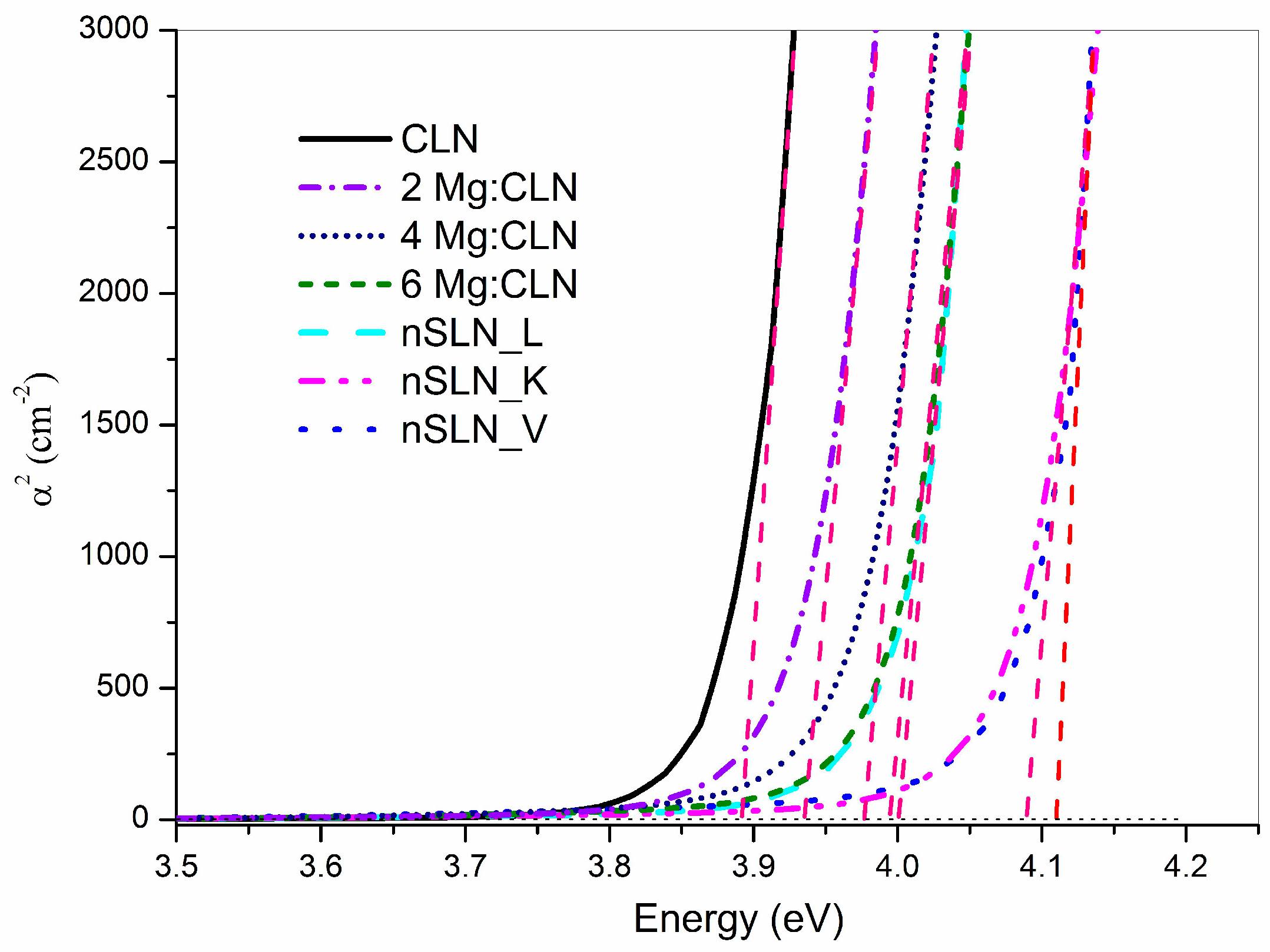
Further, the direct band-gap energy can also be estimated from the direct allowed transition using the Tauc relation (Equation (5)). For estimation, α2 vs. energy () is plotted for all the samples as shown in Figure 9. The steep rise of absorption and its linear fit at higher photon energy depict the direct allowed interband transition [93]. The intercept of the straight line at the energy axis (α2 = 0) yields the direct optical band-gap (Eg) energies which are listed in Table 2. The values show a trend similar to that for the indirect band-gap. The observed direct band-gap energy, for nSLN_V (4.11 eV) is closer to the theoretically estimated value which is 4.7 eV [95]. The observed difference between the theoretically calculated and experimentally measured value is attributed to the excitonic (quasi-particle) effects included in the theoretical model. Referring to the trend in Table 2 it appears that the experimental value will be further closer to the theoretical value [95] if the Li/Nb ratio of the sample approaches unity.
The optical absorption spectra in the visible region were further analyzed to obtain information of the defects in the samples. As shown in Figure 7 (inset), a weak broad absorption band around 2.55 eV (485 nm) was observed. This is in good agreement with the occurrence of a similar band reported in reduced CLN crystals [96]. Hence, the origin of this absorption may be attributed to oxygen vacancies present in the sample. Evidently such absorption is prominent in the nSLN_V sample where the probability of formation of an oxygen vacancy is more as the sample was kept at high temperature for long time. The mechanism of the loss of oxygen (reduction) can be represented as:
O O 1 / 2 O 2 + V O + 2 e
where VO is the oxygen vacancy carrying two positive charges. The electrons released from the oxygen site are trapped at the NbLi5+ defect sites. Depending upon the number of trapped electrons electronic defects such as bound polaron [NbLi4+] (at 1.6 eV), free polaron NbNb4+ (at 0.94 eV), bi-polarons [NbLi4+–NbNb4+] (at 2.5 eV) and Q-polarons (interaction of two bipolarons) (at 3.6 eV) [41,96,97] are formed in the lattice. So, comparing the energy values it appears that the observed absorption at 2.55 eV in the present study is due to the bi-polaron. In Mg:CLN (inset of Figure 7) there are weak peaks near 2.5 eV as well.
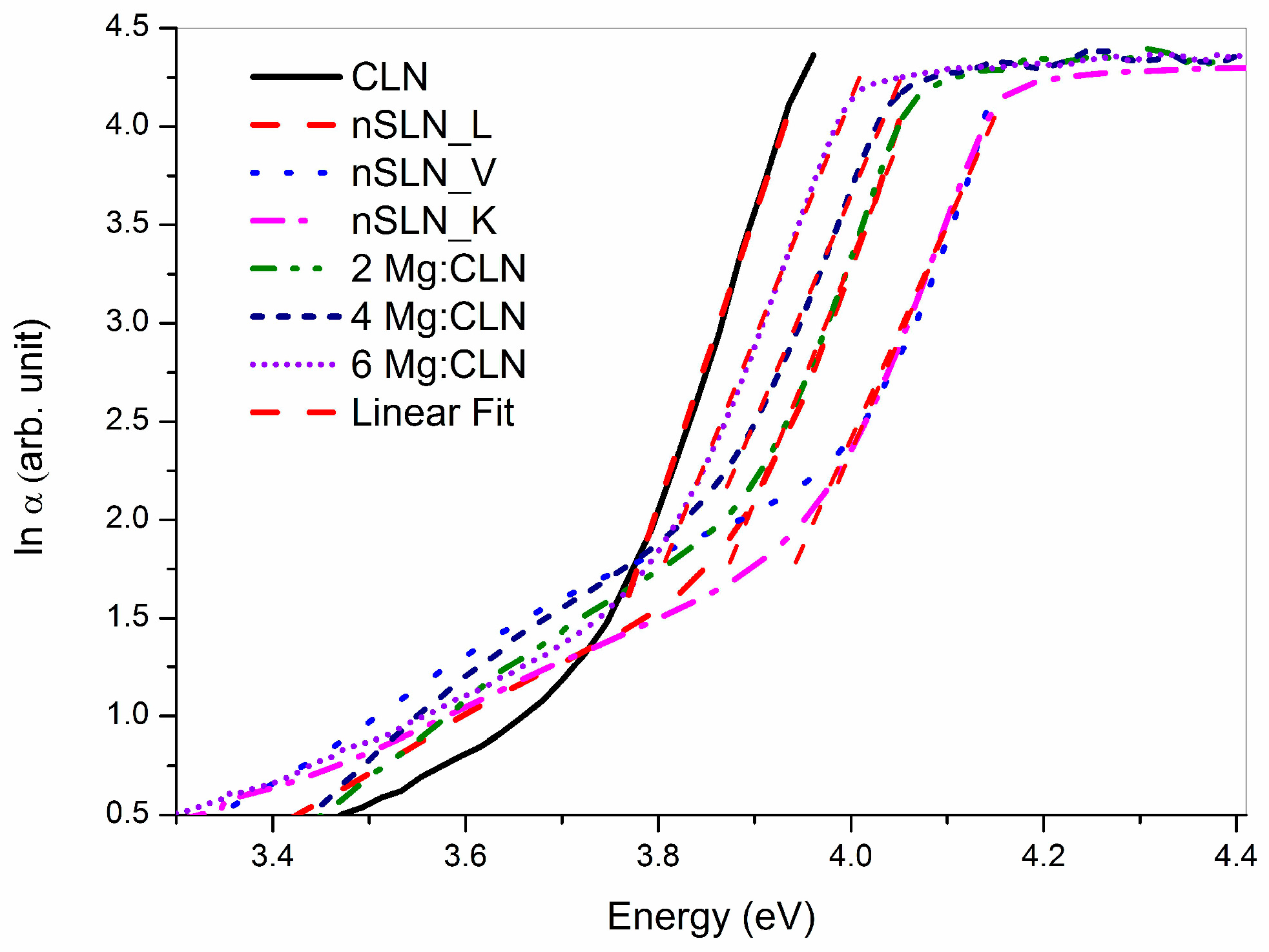
The optical absorption just above (in the wavelength plot) the fundamental AE is due to the structural defects and disorders present in the lattice. These defects give rise to an exponential tail, known as the Urbach tail, in the absorption plot (Figure 7) as their density of states falls sharply away from the conduction and valance band [98,99,100]. This is governed by the Urbach rule [98]:
α α o exp ( h v / E U )
where, αo is a characteristic crystal parameter, is the incident photon energy, and EU is the Urbach energy that corresponds to the width of the defect tail states [93,98,99].
Figure 10 shows the logarithm of absorption coefficient (lnα) vs. incident photo energy plot. As per Equation (8) the linear region shown in the figure near the band absorption edge corresponds to the Urbach tail. The Urbach energy EU was estimated from the inverse of the slope of the linear fit (Table 2). The Urbach energy for CLN (74 meV) is in good agreement with the value (74 meV) estimated by Castillo-Torres [82]. It is to be noted that although there is a decrease in the concentration fo Li vacancies and antisites defects in nSLN samples, the Urbach energy for nSLN crystals (~74 meV) was found to be slightly higher with respect to CLN (65 meV) (Table 2). This is consistent with the observation in HRXRD measurement indicating the fact that the structural defects are more in nSLN samples compared to CLN. Further, the Urbach energy of Mg:CLN is 77, 84, and 76 meV for 2, 4, and 6 mol % Mg doped samples respectively. This is also consistent with the observation in the HRXRD measurements.

6. Effect of Defect Control Processes on the Refractive Index

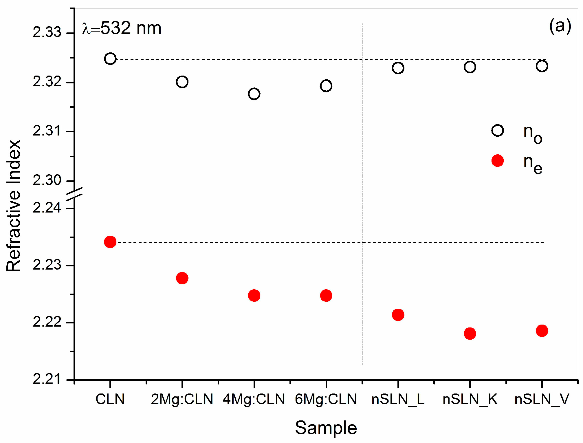
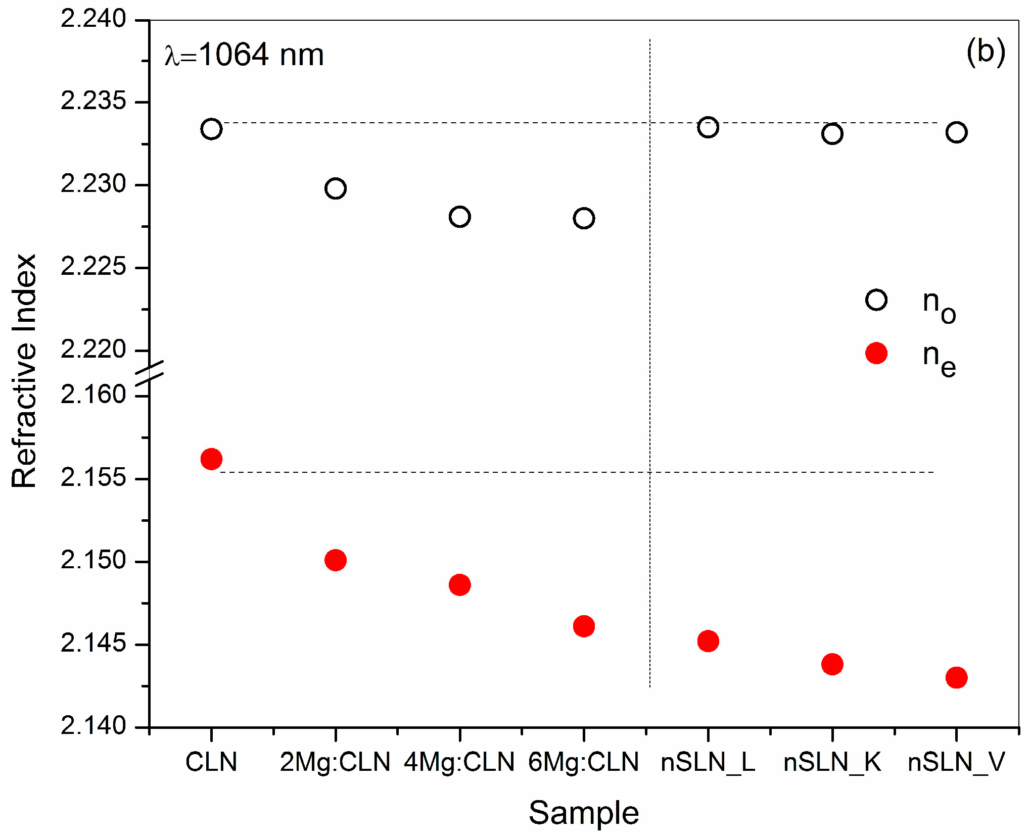
The refractive index of the samples was measured using the Prism coupling technique (Metricon 2010/M) as described in ref. [101]. Measurements were carried out for 532 and 1064 nm at room temperature. Figure 11 shows the variation of the ordinary (no) and extraordinary (ne) refractive indices for CLN along with all the three nSLN samples. It is evident from the plot that the value of no is almost unaffected by the method of the preparation of the samples, whereas the value of ne shows a decreasing trend with an increase in the Li content in the crystal (CLN > nSLN_L > nSLN_K > nSLN_V) for both 532 and 1064 nm. This correlates with the Li/Nb ratio: as the Li/Nb ratio increases the ne decreases. Figure 11 also shows the variation of both the no and ne for Mg:CLN in comparison to that of undoped CLN. A gradual decrease of no and ne with the increase in the Mg doping concentration was noticed, which is attributed to the decrease in the concentration of intrinsic defects of NbLi5+ in CLN due to Mg doping [70]. It shows that Mg ions influence the microscopic polarizability and dielectric susceptibility of CLN for both the polarizations.
The refractive index is correlated to the band gap energy (Eg) by an empirical relation [102]:
n2~1 + c/Eg
where c is a material dependent constant. The decrease in the refractive index in nSLN samples as well as for the Mg doped samples is in agreement with the trend in the shift of AE discussed earlier (Table 2).
The variation in the refractive index is explained on the basis of the nature of constitutional chemical bonds determining the polarizability of the lattice [103]. According to Pauling [103], the ionic character of a bond depends on the relative electro-negativity of the constituent ions. As the electro-negativity of Li, Nb, and O ions are 1.0, 1.2, and 3.5 respectively, the Li–O bond is more ionic than the Nb–O bond. As a result the electrons in the Li–O bonds are more tightly bound to the oxygen atom, and therefore are less polarizable compared to the Nb–O bond [104]. So, the presence of relatively more Nb–O bonds in a lattice results in higher polarizability, hence higher refractive index. Accordingly the refractive index is influenced by the Li/Nb ratio of the sample. It is evident from Figure 11 that the refractive index (especially ne) gradually decreases along with the lowering of the AE listed in Table 2 (i.e., improvement in the Li/Nb ratio) for all seven samples.
Further, Figure 12 shows the variation of the birefringence (Δn = none) in nSLN and the Mg:CLN samples for 532 and 1064 nm. The birefringence of the samples increases with the decrease in AE as a result of the decrease in the value of the ne. The VTE treated sample exhibits the highest birefringence among the samples prepared by all the methods.

7. Conclusions

Defects in the lattice adversely influence several important properties of congruent lithium niobate. There are several ways to control these defects: (a) by introduction of impurities such as Mg into the lattice within a threshold concentration limit, (b) by direct growth of LN in near-stoichiometric composition using a Li-rich melt or K2O solvent by high temperature solution growth and (c) by converting a CLN wafer into near-stoichiometric form by vapor transport equilibration in Li-rich ambience. The study shows that the best stoichiometry (Li/Nb ratio) can be achieved by growth from solution using K2O flux. However, HRXRD measurement revealed that in these crystals the crystalline quality is an issue as it contains low angle grain boundaries. The crystalline quality is the best in the VTE treated nSLN sample with an excellent Li/Nb ratio of ~0.998. However, this method is suitable only for thin wafers. For preparation of bulk crystal, nSLN grown from Li-rich melt is good in crystalline quality (FWHM ~108 arc-sec) with Li/Nb ratio of ~0.985. For optical-damage-resistant Mg doped CLN samples the crystalline quality degrades as the Mg content increases in the crystal. However, it can be minimized by employing slower pulling during the growth of the crystal. The estimation of the Urbach energy, associated with the disorder in the crystal, also supports the observations in the HRXRD measurements for all the samples. The refractive index, especially the extraordinary component (ne), was observed to decrease with an increase in the Li/Nb ratio or decrease in intrinsic defects in the case of nSLN. Whereas both the no and ne were found to decrease with an increase in the Mg content in the Mg:CLN crystals. With the absorption edge showing a blue shift, the corresponding trend in the value of the refractive index is CLN > Mg:CLNs > nSLN grown from Li-rich melt > nSLN grown using K2O solvent > VTE treated CLN. This is due to the relative decrease in the number of easily polarizable Nb–O bonds with the increase in the Li/Nb ratio. The birefringence of the samples shows a reverse trend.

Author Contributions

All the authors have contributed in conceiving and planning the work described in the manuscript; the growth of single crystals were carried out by Rajeev Bhatt, Indranil Bhaumik, Sarveswaran Ganesamoorthy, Riscob Bright and Ashwini Kumar Karnal; Rajeev Bhatt, Indranil Bhaumik and Riscob Bright prepared the samples used for the measurements and characterized those with the help of Sarveswaran Ganesamoorthy and Mohammad Soharab; all the authors participated in the data analysis and interpretation; the manuscript was prepared by Rajeev Bhatt, Indranil Bhaumik and Sarveswaran Ganesamoorthy, and finalized by Ashwini Kumar Karnal and Pradeep Kumar Gupta.

Conflicts of Interest

The authors declare no conflict of interest.

References

  1. Kosters, M.; Sturman, B.; Werheit, P.; Haertle, D.; Buse, K. Optical cleaning of congruent lithium niobate crystals. Nat. Photonics 2009, 3, 510–513. [Google Scholar] [CrossRef]
  2. Imlau, M.; Badorreck, H.; Merschjann, C. Optical nonlinearities of small polarons in lithium niobate. Appl. Phys. Rev. 2015, 2, 040606. [Google Scholar] [CrossRef]
  3. Guarino, A.; Poberaj, G.; Rezzonico, D.; Degl’Innocenti, R.; Gunter, P. Electro-optically tunable microring resonators in lithium niobate. Nat. Photonics 2007, 1, 407. [Google Scholar] [CrossRef]
  4. Soljacic, M.; Joannopoulos, J.D. Enhancement of nonlinear effects using photonic crystals. Nat. Mater. 2004, 3, 211. [Google Scholar] [CrossRef] [PubMed]
  5. Arizmendi, L. Photonic applications of lithium niobate crystals. Phys. Stat. Sol. A 2004, 201, 253. [Google Scholar] [CrossRef]
  6. Ruber, A. Chemistry and Physics of Lithium Niobate; Kaldis, E., Ed.; Current Topics in Materials Science; North-Holland Publ. Co.: Amsterdam, The Netherlands, 1978; vol. 1. [Google Scholar]
  7. Prokhorove, A.M.; Kuzminove, Y.S. Physics and Chemistry of Crystalline Lithium Niobate; Adam Hilger: Bristol, UK; New York, NY, USA, 1990. [Google Scholar]
  8. Wong, K.K. Properties of Lithium Niobate; IET: London, UK, 2002. [Google Scholar]
  9. Volk, T.; Wöhlecke, M. Lithium Niobate: Defects, Photorefraction and Ferroelectric Switching; Springer: Berlin, Germany, 2008; Volume 115. [Google Scholar]
  10. Topics in Applied Physics: Photorefractive Materials and Their Applications II; Gunter, P.; Huignard, J.P. (Eds.) Springer: Berlin, Germany, 1989; Volume 62.
  11. Armstrong, J.A.; Bloembergen, N.; Ducuing, J.; Pershan, P.S. Interactions between light waves in a nonlinear dielectric. Phys. Rev. 1962, 127, 1918. [Google Scholar] [CrossRef]
  12. Buse, K.; Adibi, A.; Psaltis, D. Nonvolatile holographic storage in doubly doped lithium niobate crystals. Nature 1998, 393, 665. [Google Scholar]
  13. Canalias, C.; Pasiskevicius, V. Mirror-less optical parametric oscillator. Nat. Photonics 2007, 1, 459. [Google Scholar] [CrossRef]
  14. Hesselink, L.; Orlov, S.S.; Liu, A.; Akella, A.; Lande, D.; Neurgaonkar, R.R. Photorefractive Materials for Nonvolatile Volume Holographic Data Storage. Science 1998, 282, 1089. [Google Scholar] [CrossRef] [PubMed]
  15. Meyn, J.-P.; Fejer, M.M. Tunable ultraviolet radiation by second-harmonic generation in periodically poled lithium tantalate. Opt. Lett. 1997, 22, 1214. [Google Scholar] [CrossRef] [PubMed]
  16. Lim, H.H.; Prakash, O.; Joo, K.B.; Pandiyan, K.; Cha, M.; Rhee, B.K. Ultra-broadband optical parametric generation and simultaneous RGB generation in periodically poled lithium niobate. Opt. Express 2007, 15, 18294. [Google Scholar] [CrossRef] [PubMed]
  17. Yu, E.N.; Choi, J.W.; Kang, H.; Ko, D.-K.; Fu, S.-H.; Liou, J.-W.; Kung, H.; Choi, H.J.; Kim, B.J.; Cha, M.; et al. Speckle noise reduction on a laser projection display via a broadband green light source. Opt. Express 2014, 22, 3547. [Google Scholar] [CrossRef] [PubMed]
  18. Heese, C.; Phillips, C.R.; Gallmann, L.; Fejer, M.M.; Keller, U. 75 MW few-cycle mid-infrared pulses from a collinear apodized APPLN-based OPCPA. Opt. Express 2012, 20, 18066. [Google Scholar] [CrossRef] [PubMed]
  19. Kitamura, K.; Furukawa, Y.; Ji, Y.; Zgonik, M.; Medrano, C.; Montemezzani, G.; Gunter, P. Photorefractive effect in LiNbO3 crystals enhanced by stoichiometry control. J. Appl. Phys. 1997, 82, 1006. [Google Scholar] [CrossRef]
  20. Xu, H.; Lee, D.; He, J.; Sinnott, S.B.; Gopalan, V.; Dierolf, V.; Phillpot, S.R. Stability of intrinsic defects and defect clusters in LiNbO3 from density functional theory calculations. Phys. Rev. B 2008, 78, 174103. [Google Scholar] [CrossRef]
  21. Schirmer, O.F.; Thiemann, O.; Wohlecke, M. Defects in LiNbO3—I. Experimental aspects. J. Phys. Chem. Solids 1991, 52, 185. [Google Scholar] [CrossRef]
  22. Gopalan, V.; Mitchell, T.E.; Furukawa, Y.; Kitamura, K. The role of nonstoichiometry in 180° domain switching of LiNbO3 crystals. Appl. Phys. Lett. 1998, 72, 1981. [Google Scholar] [CrossRef]
  23. Korkishko, Y.N.; Fedorov, V.A. Ion Exchange in Single Crystal for Integrated Optics and Optoelectronics; Cambridge International Science Publishing: Cambridge, UK, 1999. [Google Scholar]
  24. Fontana, M.; Chah, K.; Aillerie, M.; Mouras, R.; Bourson, P. Optical damage in undoped LiNbO3 crystals. Opt. Mater. 2001, 16, 111. [Google Scholar] [CrossRef]
  25. Ashkin, A.; Boyd, G.D.; Dziedzik, J.M.; Smith, R.G.; Ballman, A.A.; Nassau, K. Optically-induced refractive index inhomogeneities in LiNbO3 and LiTaO3. Appl. Phys. Lett. 1966, 9, 72. [Google Scholar] [CrossRef]
  26. Bryan, D.A.; Gerson, R.; Tomaschke, H.E. Increased optical damage resistance in lithium niobate. Appl. Phys. Lett. 1984, 44, 847. [Google Scholar] [CrossRef]
  27. Zhong, G.; Jin, J.; Wu, Z.K. Measurements of optically induced refractive-index damage of lithium niobate doped with different concentrations of MgO. J. Opt. Soc. Am. 1980, 70, 631. [Google Scholar]
  28. Choubey, R.K.; Sen, P.; Sen, P.K.; Bhatt, R.; Kar, S.; Shukla, V.; Bartwal, K.S. Optical properties of MgO doped LiNbO3 single crystals. Opt. Mater. 2006, 28, 467. [Google Scholar] [CrossRef]
  29. Bhaumik, I.; Ganesamoorthy, S.; Bhatt, R.; Karnal, A.K.; Wadhawan, V.K.; Gupta, P.K.; Kitamura, K.; Takekawa, S.; Nakamura, M. The ferroelectric phase transition in lithium tantalate single crystals: A composition dependence study. J. Appl. Phys. 2008, 103, 014108. [Google Scholar] [CrossRef]
  30. Kitamura, K.; Yamamoto, J.K.; Iyi, N.; Kimura, S.; Hayashi, T. Stoichiometric LiNbO3 single crystal growth by double crucible Czochralski method using automatic powder supply system. J. Cryst. Growth 1992, 116, 327. [Google Scholar] [CrossRef]
  31. Furukawa, Y.; Kitamura, K.; Takekawa, S.; Niwa, K.; Yajima, Y.; Iyi, N.; Mnushkina, I.; Guggenhein, P.; Martin, J. The correlation of MgO-doped near-stoichiometric LiNbO3 composition to the defect structure. J. Cryst. Growth 2000, 211, 230. [Google Scholar] [CrossRef]
  32. Bhatt, R.; Ganesamoorthy, S.; Bhaumik, I.; Sexana, A.; Karnal, A.K.; Gupta, P.K.; George, J.; Ranganathan, K. Photorefractive properties of Fe, Zn co-doped near stoichiometric LiNbO3 crystals at moderate intensities (0.5-6W/cm2). Opt. Laser Technol. 2013, 50, 112. [Google Scholar] [CrossRef]
  33. Bhatt, R.; Bhaumik, I.; Ganesamoorthy, S.; Karnal, A.K.; Gupta, P.K.; Swami, M.K.; Patel, H.S.; Sinha, A.K.; Upadhyay, A. Study of structural defects and crystalline perfection of near stoichiometric LiNbO3 crystals grown from flux and prepared by VTE technique. J. Mol. Struct. 2014, 1075, 377. [Google Scholar] [CrossRef]
  34. Bordui, P.F.; Norwood, R.G.; Jundt, D.H.; Fejer, M.M. Preparation and characterization of off-congruent lithium niobate crystals. J. Appl. Phys. 1992, 71, 875. [Google Scholar] [CrossRef]
  35. Holman, R.L.; Cressman, P.J.; Revelli, J.F. Chemical control of optical damage in lithium niobate. Appl. Phys. Lett. 1978, 32, 280. [Google Scholar] [CrossRef]
  36. Han, H.; Cai, L.; Xiang, B.; Jiang, Y.; Hui, H. Lithium-rich vapor transport equilibration in single-crystal lithium niobate thin film at low temperature. Opt. Mat. Express 2015, 5, 2634. [Google Scholar] [CrossRef]
  37. Hua, P.; Zhang, D.; Cui, Y.; Wang, Y.; Pun, E.Y.B. Off-congruent LiNbO3 crystals prepared by Li-poor vapor transport equilibration for integrated optics. Cryst. Growth Des. 2008, 8, 2125. [Google Scholar] [CrossRef]
  38. Lerner, P.; Legras, C.; Dumas, J.P. Stoechiometrie des monocristaux de metaniobate de lithium. J. Cryst. Growth 1968, 231, 3. [Google Scholar] [CrossRef]
  39. Kityk, I.V.; Janusik, M.M.; Fontana, M.D.; Alleric, M.; Abdi, F. Band structure treatment of the influence of nonstoichiometric defects on optical properties in LiNbO3. J. Appl. Phys. 2001, 90, 5542. [Google Scholar] [CrossRef]
  40. Kar, S.; Bhatt, R.; Shukla, V.; Choubey, R.K.; Sen, P.; Bartwal, K.S. Optical behaviour of VTE treated near stoichiometric LiNbO3 crystals. Solid State Commun. 2006, 137, 283. [Google Scholar] [CrossRef]
  41. Schirmer, O.F.; Imlau, M.; Merschjann, C.; Schoke, B. Electron small polarons and bipolarons in LiNbO3. J. Phys. Condens. Matter 2009, 21, 123201. [Google Scholar] [CrossRef] [PubMed]
  42. Peterson, G.E.; Carnevale, A. 93Nb NMR linewidths in nonstoichiometric lithium niobate. J. Chem. Phys. 1972, 56, 4848. [Google Scholar] [CrossRef]
  43. Fay, H.; Alford, W.J.; Dess, H.M. Dependence of second-harmonic phase-matching temperature in LiNbO3 crystals on melt composition. Appl. Phys. Lett. 1968, 12, 89. [Google Scholar] [CrossRef]
  44. Jermann, F.; Otten, J. Light-induced charge transport in LiNbO3:Fe at high light intensities. J. Opt. Soc. Am. B 1993, 10, 2085. [Google Scholar] [CrossRef]
  45. Furukawa, Y.; Kitamura, K.; Alexandrovski, A.; Route, R.K.; Fejer, M.M.; Foulon, G. Green-induced infrared absorption in MgO doped LiNbO3. Appl. Phys. Lett. 2001, 78, 1970. [Google Scholar] [CrossRef]
  46. Busacca, A.C.; Sones, C.L.; Apostolopoulos, V.; Eason, R.W.; Mailis, S. Surface domain engineering in congruent lithium niobate single crystals: A route to submicron periodic poling. Appl. Phys. Lett. 2002, 81, 4946. [Google Scholar] [CrossRef]
  47. Malovichko, G.; Grachev, V.; Schirmer, O. Interrelation of intrinsic and extrinsic defects–congruent, stoichiometric, and regularly ordered lithium niobate. Appl. Phys. B 1999, 68, 785. [Google Scholar] [CrossRef]
  48. Polgar, K.; Peter, A.; Foldvari, I. Crystal growth and stoichiometry of LiNbO3 prepared by the flux method. Opt. Mater. 2002, 19, 7. [Google Scholar] [CrossRef]
  49. Grisard, A.; Lallier, E.; Polgar, K.; Peter, A. Low electric field periodic poling of thick stoichiometric lithium niobate. Electron. Lett. 2000, 36, 1043. [Google Scholar] [CrossRef]
  50. Kong, Y.; Liu, S.; Xu, J. Recent Advances in the Photorefraction of Doped Lithium Niobate Crystals. Materials 2012, 5, 1954. [Google Scholar] [CrossRef]
  51. Xue, D.; Kitamura, K. An estimation of nonlinear optical properties of lithium niobate family ferroelectrics by the chemical bond model. Jpn. J. Appl. Phys. 2003, 42, 6230. [Google Scholar] [CrossRef]
  52. Weis, R.S.; Gaylord, T.K. Lithium niobate: Summary of physical properties and crystal structure. Appl. Phys. A 1985, 37, 191. [Google Scholar] [CrossRef]
  53. Gopalan, V.; Sanford, N.A.; Aust, J.A.; Kitamura, K.; Furukawa, Y. Ferroelectrics and Dielectrics. In Handbook of Advanced Electronic and Photonic Materials and Devices; Nalwa, H.S., Ed.; Academic Press: San Diego, CA, USA, 2001; vol. 4. [Google Scholar]
  54. Laurell, F. Periodically poled materials for miniature light sources. Opt. Mater. 1999, 11, 235. [Google Scholar] [CrossRef]
  55. Bhaumik, I.; Ganesamoorthy, S.; Bhatt, R.; Karnal, A.K.; Wadhawan, V.K.; Gupta, P.K.; Kumaragurubaran, S.; Kitamura, K.; Takekawa, S.; Nakamura, M. Dielectric and ac conductivity studies on undoped and MgO-doped near-stoichiometric lithium tantalate crystals. J. Appl. Phys. 2008, 103, 74106. [Google Scholar] [CrossRef]
  56. Broderick, N.G.R.; Ross, G.W.; Offerhaus, H.L.; Richardson, D.J.; Hanna, D.C. Hexagonally Poled Lithium Niobate: A Two-Dimensional Nonlinear Photonic Crystal. Phys. Rev. Lett. 2000, 84, 4345. [Google Scholar] [CrossRef] [PubMed]
  57. Matthias, B.T.; Remeika, J.P. Ferroelectricity in the ilmenite structure. Phys. Rev. 1949, 76, 1886. [Google Scholar] [CrossRef]
  58. Barns, R.L.; Carruthers, J.R. Lithium tantalate single crystal stoichiometry. J. Appl. Cryst. 1970, 3, 395. [Google Scholar] [CrossRef]
  59. Ballman, A.A.; Levinstein, H.J.; Capio, C.D.; Brown, H. Optical waveguiding layers in LiNbO3 and LiTaO3. J. Am. Ceram. Soc. 1967, 50, 657. [Google Scholar] [CrossRef]
  60. O’Bryan, H.M.; Gallagher, P.K.; Brandle, C.D. Congruent composition and li-rich phase boundary of LiNbO3. J. Am. Ceram. Soc. 1985, 68, 493. [Google Scholar] [CrossRef]
  61. Iyi, N.; Kitamura, K.; Yajima, Y.; Kimura, S.; Furukawa, Y.; Sato, M. Defect structure model of MgO-doped LiNbO3. J. Solid State Chem. 1995, 118, 148. [Google Scholar] [CrossRef]
  62. Sweeney, K.C.; Hulliburton, L.E.; Bryan, D.A.; Rice, R.R.; Gerson, R.; Tomaschbe, H.E. Point defects in Mg-doped lithium niobate. J. Appl. Phys. 1985, 57, 1036. [Google Scholar] [CrossRef]
  63. Chen, S.S.; Liu, H.D.; Kong, Y.F.; Huang, Z.H.; Xu, J.J.; Zhang, G.Y. The resistance against optical damage of near-stoichiometric LiNbO3:Mg crystals prepared by vapor transport equilibration. Opt. Mater. 2007, 29, 885. [Google Scholar] [CrossRef]
  64. Grabmaier, B.C.; Otto, F. Growth and investigation of MgO-doped LiNbO3. J. Cryst. Growth 1986, 79, 682. [Google Scholar] [CrossRef]
  65. Sen, P.; Sen, P.K.; Bhatt, R.; Kar, S.; Shukla, V.; Bartwal, K.S. The effect of MgO doping on optical properties of LiNbO3 single crystals. Solid State Commun. 2004, 129, 747. [Google Scholar] [CrossRef]
  66. Bhatt, R.; Kar, S.; Shukala, V.; Sen, P.; Sen, P.K.; Bartwal, K.S.; Wadhawan, V.K. Studies on nonlinear optical properties of ferroelectric MgO-LiNbO3 single crystals. Ferroelectrics 2005, 323, 165. [Google Scholar] [CrossRef]
  67. Volk, T.R.; Pryalkin, V.I.; Rubinina, N.M. Optical-damage-resistant LiNbO3:Zn crystal. Opt. Lett. 1990, 15, 996. [Google Scholar] [CrossRef] [PubMed]
  68. Kokanyan, E.P.; Razzari, L.; Cristiani, I.; Degiorgio, V.; Gruber, J.B. Reduced photorefraction in hafnium-doped single-domain and periodically poled lithium niobate crystals. Appl. Phys. Lett. 2004, 84, 1880. [Google Scholar] [CrossRef]
  69. Razzari, L.; Minzioni, P.; Cristiani, I.; Degiorgio, V.; Kokanyan, E.P. Photorefractivity of Hafnium-doped congruent lithium–niobate crystals. Appl. Phys. Lett. 2005, 86, 131914. [Google Scholar] [CrossRef]
  70. Riscob, B.; Bhaumik, I.; Ganesamoorthy, S.; Bhatt, R.; Vijayan, N.; Karnal, A.K.; Wahab, M.A.; Bhagavannarayana, G. Effect of Mg doping on the growth aspects, crystalline perfection, and optical and thermal properties of congruent LiNbO3 single crystals. J. Appl. Cryst. 2013, 46, 1854. [Google Scholar] [CrossRef]
  71. Bhaumik, I.; Ganesamoorthy, S.; Bhatt, R.; Sundar, R.; Karnal, A.K.; Wadhawan, V.K. Novel seeding technique for growing KTiOPO4 single crystals by the TSSG method. J. Cryst. Growth 2002, 243, 522. [Google Scholar] [CrossRef]
  72. Santos, M.T.; Rojo, J.C.; Cintas, A.; Arizmendi, L.; Dieguez, E. Changes in the solid-liquid interface during the growth of Bi12SiO20, Bi12GeO20 and LiNbO3 crystals grown by the Czochralski method. J. Cryst. Growth 1995, 156, 413. [Google Scholar] [CrossRef]
  73. Xu, H.; Lee, D.; Sinnott, S.B.; Gopalan, V.; Dierolf, V.; Phillpot, S.R. Structure and energetics of Er defects in LiNbO3 from first-principles and thermodynamic calculations. Phys. Rev. B 2009, 80, 144104. [Google Scholar] [CrossRef]
  74. Bhatt, R.; Ganesamoorthy, S.; Bhaumik, I.; Karnal, A.K.; Gupta, P.K. Optical bandgap and electrical conductivity studies on near stoichiometric LiNbO3 crystals prepared by VTE process. J. Phys. Chem. Solids 2012, 73, 257. [Google Scholar] [CrossRef]
  75. Yoo, K.C.; Henningsen, T.; Dawson, K.D.G.; Singh, N.B.; Hopkins, R.H. Effects of subgrain structures on the optical homogeneity of Tl3AsSe3 single crystals. J. Appl. Phys. 1988, 64, 827. [Google Scholar] [CrossRef]
  76. Riscob, B.; Bhatt, R.; Vijayan, N.; Bhaumik, I.; Ganesamoorthy, S.; Wahab, M.A.; Rashmi; Bhagavannarayana, G. Structural, optical and thermal properties of Zr–Fe co-doped congruent LiNbO3 single crystals. J. Appl. Cryst. 2013, 46, 601. [Google Scholar] [CrossRef]
  77. Bhatt, R.; Ganesamoorthy, S.; Bhaumik, I.; Karnal, A.K.; Bhagavannarayana, G.; Gupta, P.K. Effect of annealing in Li-rich ambient on the optical absorption and crystallinity of Er doped LiNbO3 crystals. J. Optoelectron. Adv. Mater. 2011, 13, 245. [Google Scholar]
  78. Lal, K.; Bhagavannarayana, G. A high-resolution diffuse X-ray scattering study of defects in dislocation-free silicon crystals grown by the float-zone method and comparison with Czochralski-grown crystals. J. Appl. Cryst. 1989, 22, 209. [Google Scholar] [CrossRef]
  79. Kushwaha, S.K.; Vijayan, N.; Maurya, K.K.; Kumar, A.; Kumar, B.; Somayajulu, K.; Bhagavannarayana, G. Enhancement in crystalline perfection and optical properties of benzophenone single crystals: The remarkable effect of a liquid crystal. J. Appl. Cryst. 2011, 44, 839. [Google Scholar] [CrossRef]
  80. Hurle, D.T.J. Handbook of Crystal Growth: Bulk Crystal Growth A: Basic Techniques; North-Holland Elsevier Science Publishers: Amsterdam, The Netherlands, 1994; Vol. 2. [Google Scholar]
  81. Tauc, J.C. Optical Properties of Solids; North-Holland: Amsterdam, The Netherlands, 1972. [Google Scholar]
  82. Castillo-Torres, J. Optical absorption edge analysis for zinc-doped lithium niobate. Opt. Commun. 2013, 290, 107. [Google Scholar] [CrossRef]
  83. Kovacs, L.; Ruschhaupt, G.; Polgar, K.; Corradi, G.; Wohlecke, M. Composition dependence of the ultraviolet absorption edge in lithium niobate. Appl. Phys. Lett. 1997, 70, 2801. [Google Scholar] [CrossRef]
  84. Peter, A.; Polgar, K.; Ferriol, M.; Poppl, L.; Foldvari, I.; Cochez, M.; Szalle, Z.S. Ternary system Li2O–K2O–Nb2O5: Part II: Growth of stoichiometric lithium niobate. J. Alloy. Compd. 2005, 386, 246. [Google Scholar] [CrossRef]
  85. Wang, H.L.; Hang, Y.; Xu, J.; Zhang, L.H.; Zhu, S.N.; Zhu, Y.Y. Near-stoichiometric LiNbO3 crystal grown using the Czochralski method from Li-rich melt. Mater. Lett. 2004, 58, 3119. [Google Scholar] [CrossRef]
  86. Polgar, K.; Peter, A.; Kovacs, L.; Corradi, G.; Szaller, Z. Growth of stoichiometric LiNbO3 single crystals by top seeded solution growth method. J. Cryst. Growth 1997, 177, 211. [Google Scholar] [CrossRef]
  87. Serrano, M.D.; Bermudez, V.; Arizmendi, L.; Dieguez, E. Determination of the Li/Nb ratio in LiNbO3 crystals grown by Czochralski method with K2O added to the melt. J. Cryst. Growth 2000, 210, 670. [Google Scholar] [CrossRef]
  88. Chen, C.-Y.; Chen, J.-C.; Chia, C.T. Growth and optical properties of different compositions of LiNbO3 single crystal fibers. Opt. Mater. 2007, 30, 393. [Google Scholar] [CrossRef]
  89. Chen, Y.; Zhang, W.; Shu, Y.; Lou, C.; Kong, Y.; Huang, Z. Determination of the Li/Nb ratio in LiNbO3 crystals prepared by vapor transport equilibration method. Opt. Mater. 2003, 23, 295. [Google Scholar] [CrossRef]
  90. Abrahams, S.C.; Marsh, P. Defect structure dependence on composition in lithium niobate. Acta Cryst. B 1986, 42, 61. [Google Scholar] [CrossRef]
  91. Chen, Y.L.; Xu, J.J.; Kong, Y.F.; Chen, S.L.; Zhang, G.Y.; Wen, J.P. Effect of Li diffusion on the domain inversion of LiNbO3 prepared by vapor transport equilibration. Appl. Phys. Lett. 2002, 81, 700. [Google Scholar] [CrossRef]
  92. Schmidt, W.G.; Albrecht, M.; Wippermann, S.; Blankenburg, S.; Rauls, E. LiNbO3 ground and excited state properties from first-principles calculations. Phys. Rev. B 2008, 77, 035106. [Google Scholar] [CrossRef]
  93. Bhatt, R.; Bhaumik, I.; Ganesamoorthy, S.; Karnal, A.K.; Swami, M.K.; Patel, H.S.; Gupta, P.K. Urbach tail and bandgap analysis in near stoichiometric LiNbO3 crystals. Phys. Status Solidi A 2012, 209, 176. [Google Scholar] [CrossRef]
  94. Zhang, Y.; Guilbert, L.; Bourson, P.; Polgar, K.; Fontana, M.D. Characterization of short-range heterogeneities in sub-congruent lithium niobate by micro-Raman spectroscopy. J. Phys. Condens. Matter 2006, 18, 957. [Google Scholar] [CrossRef]
  95. Thierfelder, C.; Sanna, S.; Schindlmayr, A.; Schmidt, W.G. Do we know the band gap of lithium niobate? Phys. Status Solidi C 2010, 7, 362. [Google Scholar] [CrossRef]
  96. Dhar, A.; Mansingh, A. On the correlation between optical and electrical properties in reduced lithium niobate crystals. J. Phys. D Appl. Phys. 1991, 24, 1644. [Google Scholar] [CrossRef]
  97. Akhmadullin, I.S.; Golenishchev-Kutuzov, V.A.; Migachev, S.A. Electronic structure of deep centers in LiNbO3. Phys. Solid State 1998, 40, 1012. [Google Scholar] [CrossRef]
  98. Urbach, F. The long-wavelength edge of photographic sensitivity and of the electronic absorption of solids. Phys. Rev. 1953, 92, 1324. [Google Scholar] [CrossRef]
  99. Redfield, D.; Burke, W.J. Optical absorption edge of LiNbO3. J. Appl. Phys. 1974, 45, 4566. [Google Scholar] [CrossRef]
  100. John, S.; Soukoulis, C.; Cohen, M.H.; Economou, E.N. Theory of electron band tails and the Urbach optical absorption edge. Phys. Rev. Lett. 1986, 57, 1777. [Google Scholar] [CrossRef] [PubMed]
  101. Bhaumik, I.; Bhatt, R.; Ganesamoorthy, S.; Saxena, A.; Karnal, A.K.; Gupta, P.K.; Sinha, A.K.; Deb, S.K. Temperature-dependent index of refraction of monoclinic β-Ga2O3 single crystal. Appl. Opt. 2011, 50, 6006. [Google Scholar] [CrossRef] [PubMed]
  102. Wempal, S.; Didomenico, D. Oxygen-octahedra ferroelectrics-I. Theory of electro-optical and nonlinear optical effects. J. Appl. Phys. 1969, 40, 735. [Google Scholar] [CrossRef]
  103. Philips, J.C. Ionicity of the chemical bond in crystals. Rev. Mod. Phys. 1970, 42, 317. [Google Scholar] [CrossRef]
  104. Levine, B.F. d-electron effects on bond susceptibilities and ionicities. Phys. Rev. B 1973, 7, 2591. [Google Scholar] [CrossRef]
Figure 1. Schematic of the defect structure of a congruent LiNbO3 crystal [20].
Crystals 07 00023 g001
Figure 2. As-grown (a) undoped and (b) Mg (2, 4 and 6 mol % from left to right) doped congruent LiNbO3 crystals.
Crystals 07 00023 g002
Figure 3. Near-stoichiometric LiNbO3 crystals grown from (a) Li-rich melt (nSLN_L) and (b) K2O solvent (nSLN_K).
Crystals 07 00023 g003
Figure 4. (a) Conoscopy and (b) birefringence fringe patterns for a Mg:CLN crystal.
Crystals 07 00023 g004
Figure 5. High resolution X-ray diffraction (HRXRD) curves of (a) undoped; (b) 2.0; (c) 4.0; and (d) 6.0 mol % Mg-doped CLN crystals.
Crystals 07 00023 g005
Figure 6. HRXRD curves of (a) SLN_L; (b) SLN_V; and (c) SLN_K crystals.
Crystals 07 00023 g006
Figure 7. Absorption spectra of CLN, Mg doped CLN and nSLN crystals. Inset shows absorption band due to bi-polaron absorption at around 2.55 eV.
Crystals 07 00023 g007
Figure 8. Dependence of α1/2 on incident photon energy () for (a) Mg:CLN; (b) undoped CLN and nSLN crystals.
Crystals 07 00023 g008
Figure 9. Dependence of α2 on incident photon energy () of CLN, Mg:CLN, and nSLN crystals.
Crystals 07 00023 g009
Figure 10. The dependence of lnα with incident photon energy.
Crystals 07 00023 g010
Figure 11. Refractive index (no and ne) of different (a) Mg:CLN; and (b) nSLN crystals at 532 and 1064 nm wavelength.
Crystals 07 00023 g011aCrystals 07 00023 g011b
Figure 12. Birefringence at 532 and 1064 nm of differently prepared lithium niobate crystals.
Crystals 07 00023 g012
Table 1. A few properties of congruent lithium niobate (CLN) and near-stoichiometric lithium niobate (nSLN) crystals [9,10].
ParameterCLNnSLN
Li2O:Nb2O548.6:51.449.9:50.1
Non-linear optical coefficient (pm/V) @ λ = 633 nmd13 = 6.1d13 = 6.3
d33 = 34.1d33 = 44.0 (33% Higher)
Linear electo-optic coefficient (pm/V) @ λ = 1064 nmr31 = 10.0r31 = 10.4
r33 = 31.5r33 = 38.3 (22% Higher)
Coercive field (kV/mm) @ room temperature~21<4 (80% Lower)
Table 2. High resolution X-ray diffraction (HRXRD) and optical parameters of the LiNbO3 crystals prepared by different methods.
SampleFWHM of DC (arc-sec)AE (nm)Li/Nb (by Equation (4))Egind (eV)Ep (meV)Egd (eV)EU (meV)
CLN29320.60.9363.7440.53.8964.9
2Mg:CLN76317.1*3.7739.23.9380.1
4Mg:CLN112314.2*3.8235.13.9782.2
6Mg:CLN65311.6*3.8634.23.9974.4
nSLN_L108310.20.9853.8342.54.0074.0
nSLN_Kmulti-peak305.50.9963.9332.14.0974.1
nSLN_V65304.60.9983.9733.34.1173.6
* Equation (4) is not valid for Mg doped samples.