3.1. Effect of the Number of Textile Layers
The influence of different textile layers on the flexural behaviour of TRC specimens is presented through the load–deflection curves in
Figure 7. In
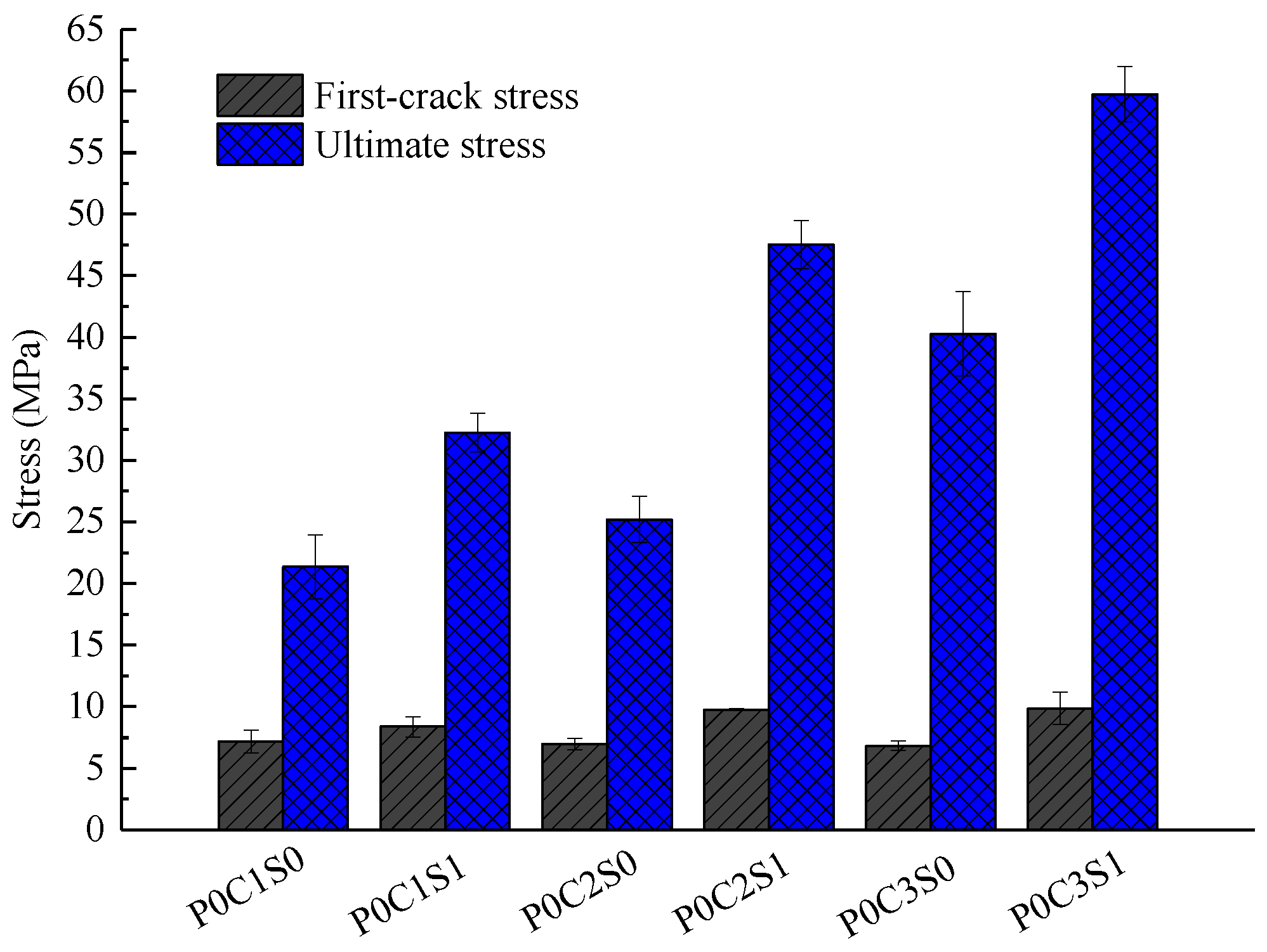
Figure 8, the first-crack and ultimate stresses of the specimens are compared. The experimental data, including the first-crack load, first-crack stress, ultimate load, ultimate stress, ultimate deflection, flexural toughness and crack number, of all the TRC specimens are listed in
Table 6. Toughness, which is an important index for presenting the energy absorption capability of the TRC specimens, is calculated as the area under the load–deflection curve.
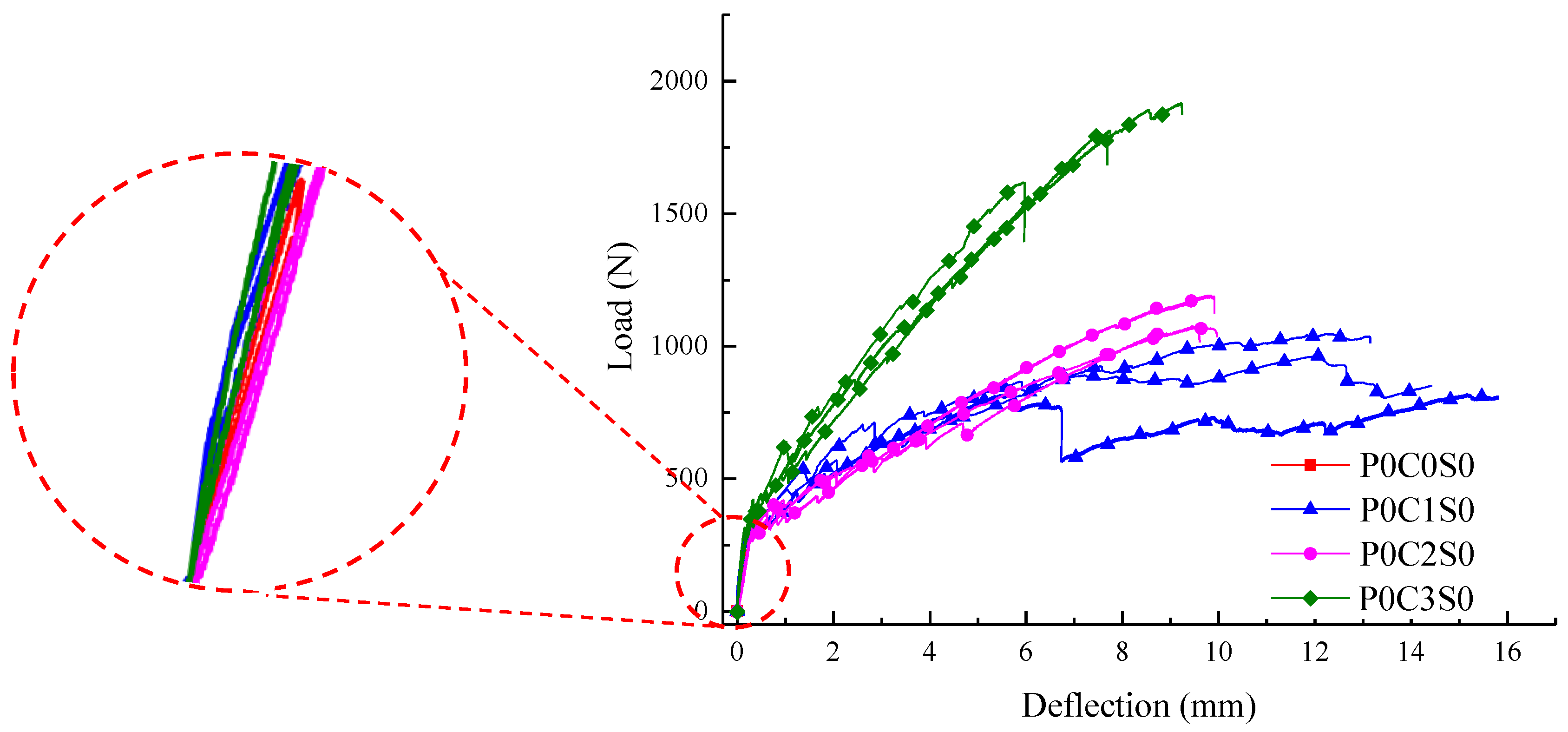
The load increased linearly with the deflection for the un-cracked specimens, as shown in
Figure 7. After cracking, the curves showed considerable difference between unreinforced and reinforced specimens. For the unreinforced specimens, the load suddenly dropped after the first crack appeared, and the specimens showed a brittle failure with a single crack. For the TRC specimen, the load-deflection curve started to fluctuate after the first crack appeared, and the load continued to increase after a course of fluctuation. Finally, failure of the TRC specimen occurred after reaching the ultimate load.
The bearing capacity of the TRC specimens gradually improved with increased textile layers, as displayed in
Figure 7 and
Figure 8 and
Table 6. The average ultimate stress of one-layer TRC specimens was 21.35 MPa. The average ultimate stress of two-layer and three-layer TRC specimens increased by approximately 17.6% and 88.7%, respectively, compared with the one-layer TRC specimens. The two-layer TRC specimens failed in debonding along the matrix-textile interface, and the tensile strength of the textiles was not utilized. However, the three-layer TRC specimens showed shear failure mode. Therefore, the ultimate stress of the three-layer TRC specimens was greatly improved.
In
Figure 7, the slope of the curve in the post-cracking stage was lower than that in the pre-cracking stage, which indicated that the flexural stiffness of the cracked TRC specimen reduced. However, smaller reduction in the flexural stiffness could be observed with the increase in the textile layers. In the post-cracking stage, the crack width increased and cracks propagated upward as the load increased. Thus, the neutral axis of the TRC specimen moved upward, and the contribution of the textiles on the section stiffness becomes more noticeable because the textiles mainly bore the tension force at the cracks. Therefore, smaller reduction in post-cracking flexural stiffness of the TRC specimens could be observed with increased textile layers [
23]. Simultaneously, the deformation of the specimen under the same load was reduced with increasing number of textile layers.
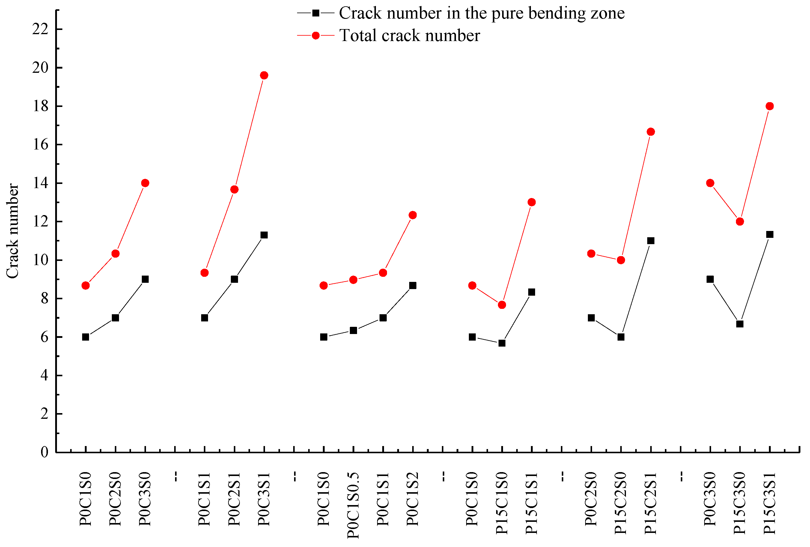
Figure 9 exhibits the crack patterns of P0C1S0, P0C2S0, and P0C3S0. The crack numbers in the tension and pure bending zones of all the specimens were compared, as shown in
Figure 10. The TRC specimens showed multiple cracking behaviour under loading. The cracks were uniformly distributed in the tension zone of the specimens, and most of them appeared in the pure bending zone of the specimens. When the cracking moment of the weakest section was reached, the first crack appeared at the corresponding location of the TRC specimen. As the load continued to increase, another crack appeared at the next weak section of the specimen. Repetition of this process led to the phenomenon of multiple cracking of the TRC specimens. In general, increased textile layers result in increased crack number but reduced average crack spacing, as shown in
Figure 10 and
Table 6.
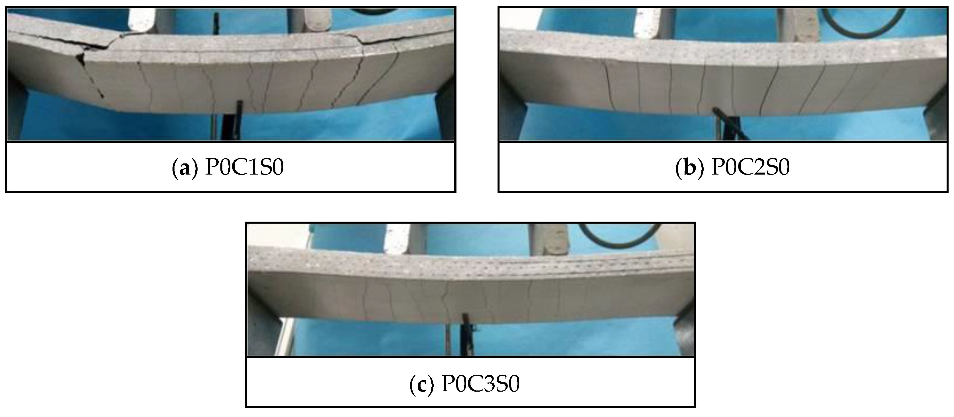
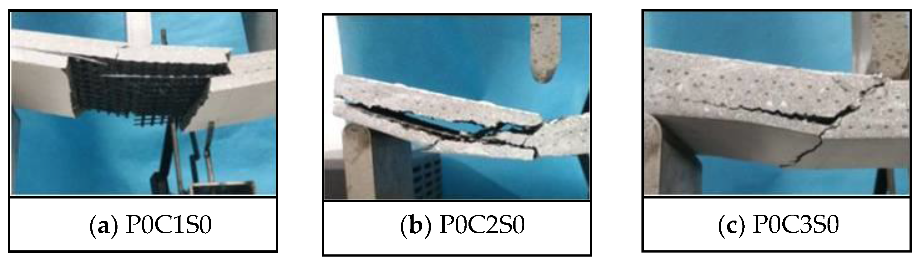
Figure 11 exhibits the failure modes of P0C1S0, P0C2S0, and P0C3S0. The failure of P0C1S0 and P0C2S0 resulted from the longitudinal crack along the matrix-textile interface, and the longitudinal crack propagated with the increased load. Finally, P0C1S0 and P0C2S0 broke down due to the collapse of the matrix, as shown in
Figure 11a,b. However, P0C3S0 demonstrated the typical shear failure accompanied by slight matrix-textile interfacial debonding, as shown in
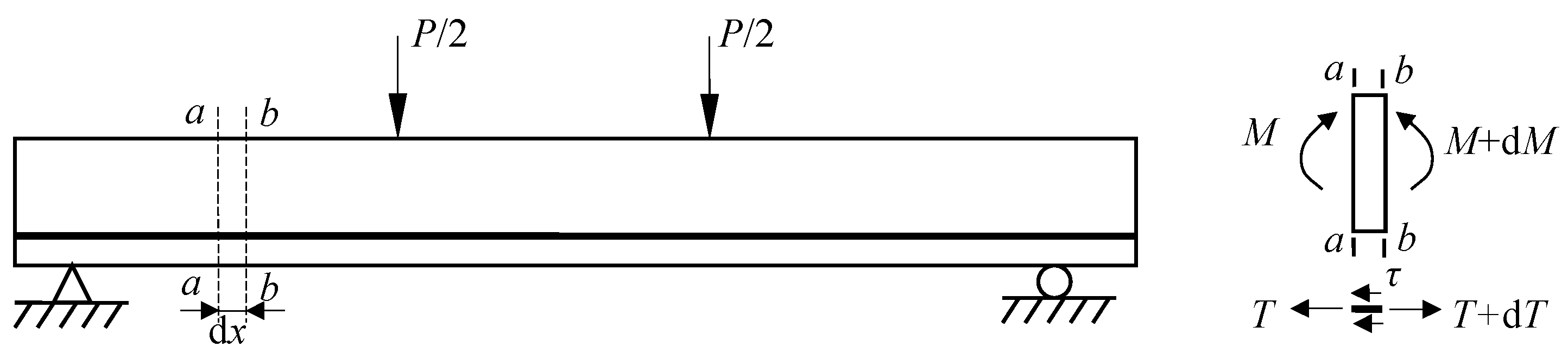
Figure 11c. The possibility of debonding failure in the TRC specimen declined with increasing number of textile layers. As demonstrated in
Figure 12 , an infinitesimal segment of length d
x was taken from the shear-bending zone of the TRC specimens. A tension increment d
T of the textile between the
b-
b section and
a-
a section was apparent because the moment in the
b-
b section was greater than that in the
a-
a section. The interfacial stress on the textile along the infinitesimal segment of length d
x could balance the tension increment d
T. The textiles were separated from the matrix when the interfacial stress exceeded the bond strength of the matrix-textile interface. However, under the same load, the tensile stress of the textile was reduced with increasing number of textile layers. Thus, the tension increment d
T of the textile along the infinitesimal segment of length d
x was reduced, as well as the matrix-textile interfacial stress. The debonding length along the matrix-textile interface was consequently shortened with increasing number of textile layers.
3.2. Effect of Steel Fibres
Figure 13 shows the load-deflection responses of the specimens P0C1S1, P0C2S1, and P0C3S1. The first-crack and ultimate stresses of the specimens are compared in
Figure 8. In
Figure 13, the load of specimen P0C0S1 slightly decreased after the ultimate load, and 2–3 cracks could be observed at failure of the specimen. This phenomenon indicated that the ductility of the plain matrix was improved by steel fibres. In
Figure 8 and
Table 6, the ultimate stress of P0C0S1 was 12.54 MPa, which increased by 151.3% in comparison with the plain matrix. In comparison with those of P0C1S0, the first-crack stress, ultimate stress and toughness of P0C1S1 increased by 16.7%, 51.1%, and 23.5%, respectively. The first-crack stress, ultimate stress and toughness of P0C2S1 increased by 39.8%, 89.2%, and 143.1%, respectively, compared with those of P0C2S0. The first-crack stress, ultimate stress and toughness of P0C3S1 increased by 44.3%, 48.3%, and 119.1%, respectively, compared with those of P0C3S0. The steel fibres in the matrix improved the crack resistance of the specimens, and as a result, the first-crack stress was increased. In addition, the steel fibres inserted into the grids of the textiles improved the interfacial bonding performance between the textile and matrix, and as a result, the ultimate stress and flexural toughness were increased. With increased number of textile layers, the influence of the steel fibres on first-crack stress and flexural toughness became more pronounced. However, the influence of the steel fibres on the ultimate stress of the two-layer specimen was most significant compared with that of the one-layer and three-layer specimens. The two-layer TRC specimens without steel fibres showed serious debonding failure, and the tensile strength of the textile was not utilized. However, the matrix-textile interfacial bonding performance of the two-layer specimens was improved due to the steel fibres, thereby providing a better utilization of the textiles. Therefore, the ultimate stress of the two-layer specimens were significantly improved.
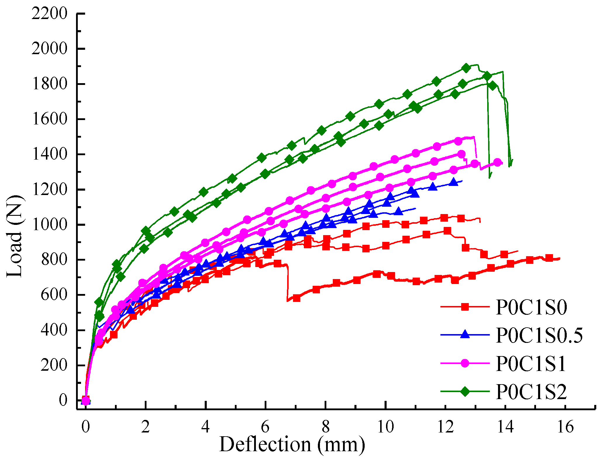
Figure 14 shows the load-deflection responses of the TRC specimens with single layer of textile and 0.5%, 1%, and 2% volume content of steel fibres. In
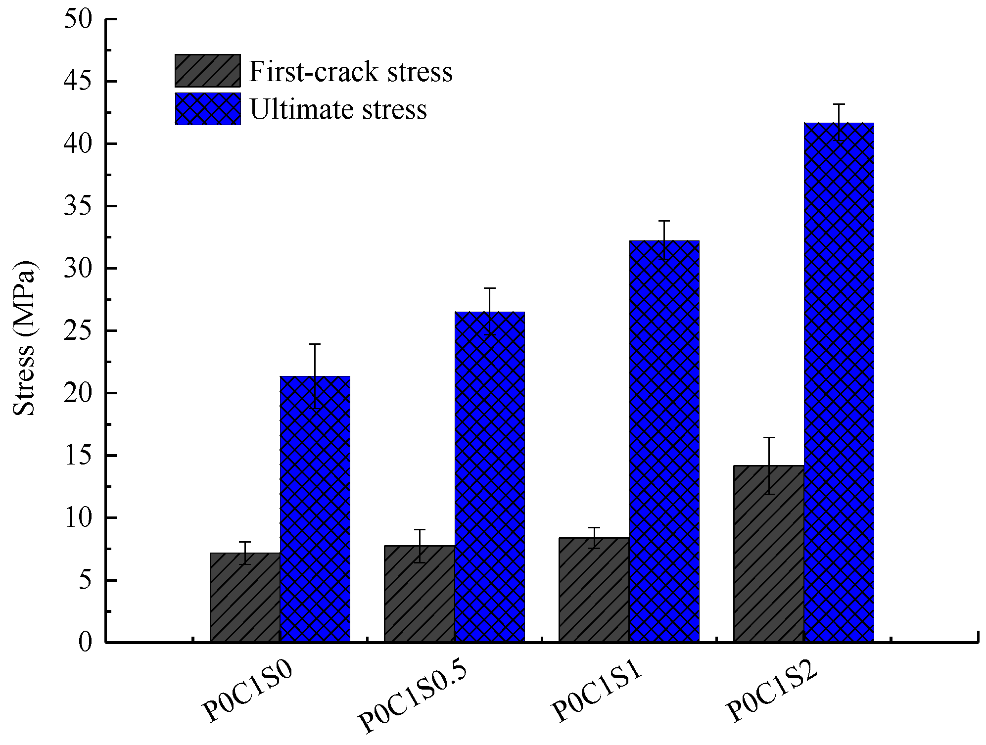
Figure 15, the first-crack and ultimate stresses of the corresponding specimens were compared. In
Figure 14 and
Figure 15 and
Table 6, the first-crack stress of the specimens with 0.5%, 1%, and 2% volume content of steel fibres increased by 7.8%, 16.7%, and 84.7%, respectively, compared with those of P0C1S0. The increments in ultimate stress for the specimens with 0.5%, 1%, and 2% volume content of steel fibres were 24.3%, 51%, and 95.4%, respectively, compared with those of P0C1S0. A 0.5% volume content of steel fibres did not show considerable effect on the flexural toughness of the specimen. However, the flexural toughness of the specimens with 1% and 2% volume content of steel fibres increased by 23.5% and 73.5%, respectively, compared with those of P0C1S0. Within the scope of the test, the first-crack stress and ultimate stress improved with increasing volume content of steel fibres, and improvement in the ultimate stress was greater than that in the first-crack stress. When the volume content of steel fibres is 0.5%, the defects in the matrix due to the addition of steel fibres decrease the ultimate deflection of the specimens, thus no improvement on the flexural toughness of the specimens with 0.5% volume content of steel fibres can be observed. Moreover, the load-deflection curve became smoother with the increase in the steel fibres in the specimen.
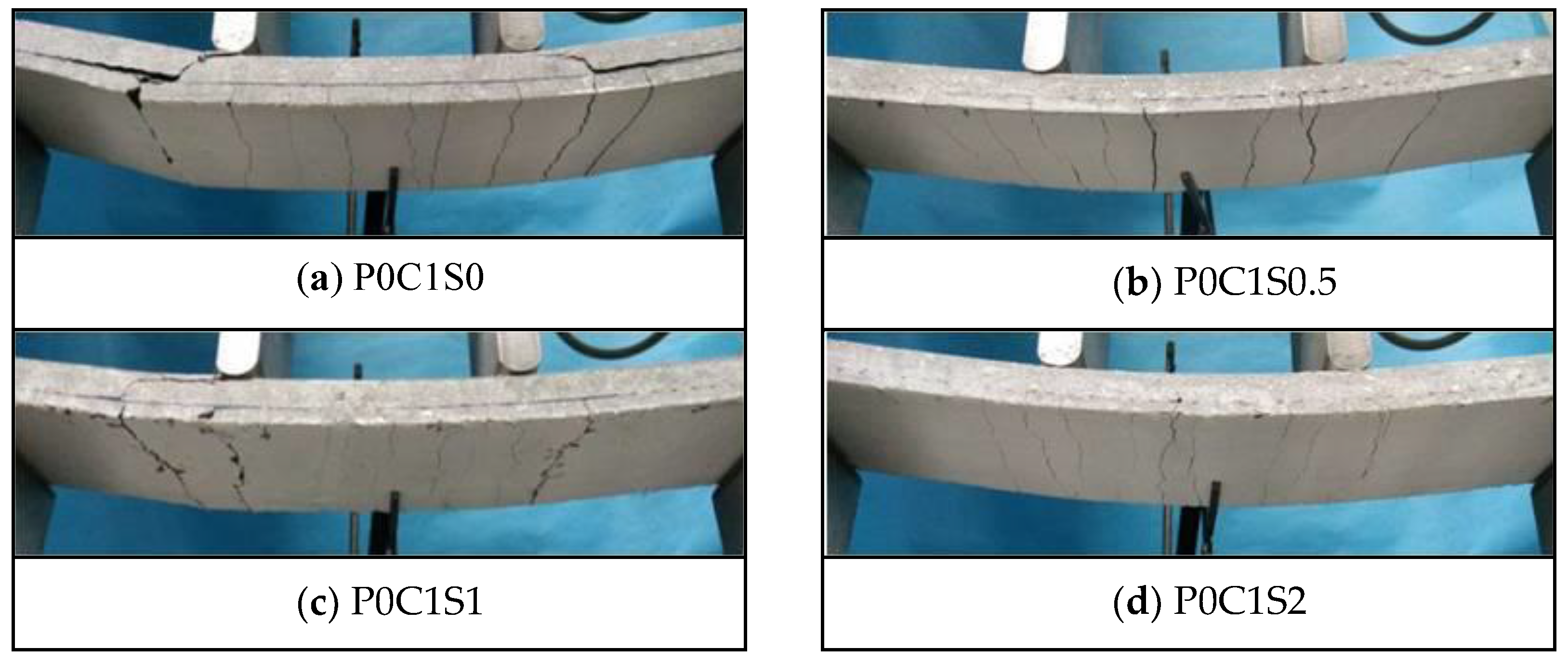
Figure 16 demonstrates the cracking patterns of specimens P0C1S0, P0C1S0.5, P0C1S1, and P0C1S2. The steel fibres could effectively increase the crack number of the specimens and reduce the average crack spacing accordingly, as displayed in
Figure 12 and
Figure 16 and
Table 6. The cracks at the bottom of P0C1S0 and P0C1S0.5 were straight continuous cracks, and the cracks at the bottom of P0C1S1 and P0C1S2 were irregular short cracks. Increasing the volume content of steel fibres resulted in its increased restraint to matrix, changing the cracking pattern at the bottom of the specimens. The bridging effect of the steel fibres considerably restrained the propagation of cracks. However, the ultimate deflection of the TRC specimens with more steel fibres increased, which led to the increase in the total width of the cracks at the bottom of the specimens. As a result, the crack number was increased, and the average crack spacing was reduced.
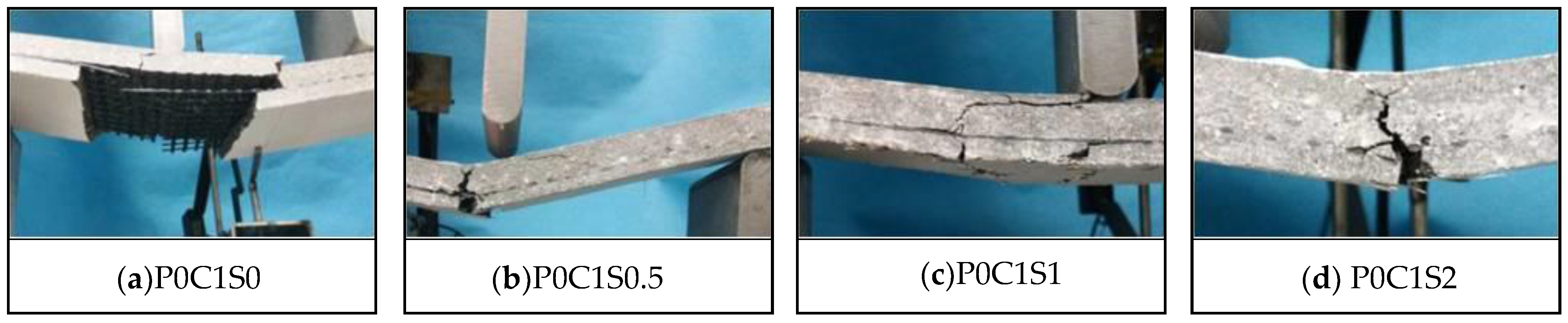
The failure modes of the TRC specimens with different volume contents of steel fibres are shown in
Figure 17. When P0C1S2 failed, the bottom textile was broken, and debonding along the matrix-textile interface did not occur, as depicted in
Figure 17d. The 2% volume content of steel fibres in the specimens prevented the matrix-textile interfacial debonding. Meanwhile, no obvious oblique crack could be observed on P0C1S2, which indicated that the shear behaviour of the specimen improved. In
Figure 17b,c, the P0C1S0.5 and P0C1S1 failed along with matrix-textile interfacial debonding, and the failure mode of P0C1S1 was shear failure. The failure modes of P0C1S0.5 and P0C1S1 indicated that the 0.5% and 1% volume contents of steel fibres could not adequately improve the matrix-textile interfacial bonding performance and shear behaviour.
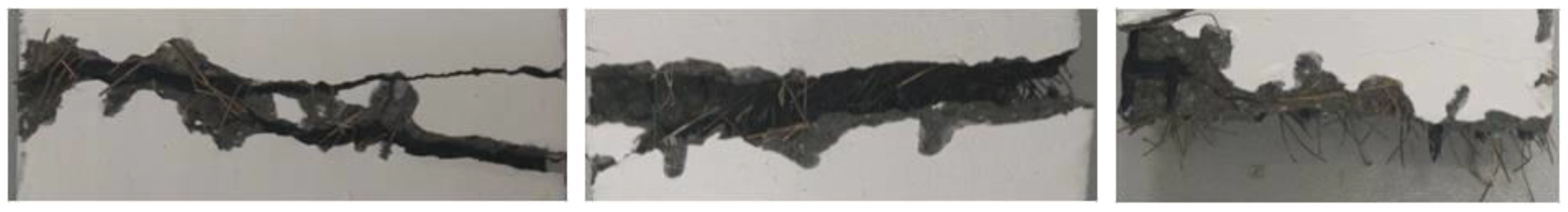
In general, the steel fibres improved the bearing capacity and flexural toughness of the TRC specimens. The cracking pattern, which featured multiple-cracking behaviour, could be observed on the specimens with steel fibres. The steel fibres that bridged over the cracks (
Figure 18) were pulled out with the increase in crack width. The process of pulling out the steel fibres consumed energy, resulting in the improvement of the flexural toughness. Simultaneously, the steel fibres that bridged over the cracks bore the tensile stress transferred from the cracking matrix, thus improving the bearing capacity of the specimens. The anchoring effect of the steel fibres inserted in the grids of the textiles prevented relative slip between the textiles and matrix, resulting in the improvement of the matrix-textile interfacial bonding performance. Improved interfacial bonding performance could ensure co-working between the textile and matrix and better use of the tensile strength of the textiles. As a result, the bearing capacities of the TRC specimens were improved. Moreover, the crack number was increased, average crack spacing was reduced and the load-deflection curves became smooth with increased volume of steel fibres.
3.3. Effect of Prestress
In this section, the influence of 15% prestress level on the flexural behaviour of the TRC specimens, and the influence of 1% volume content of steel fibres on the flexural behaviour of TRC specimens with 15% prestress level are discussed.
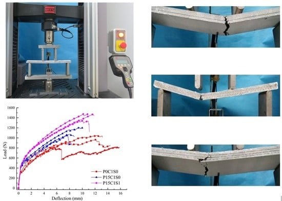
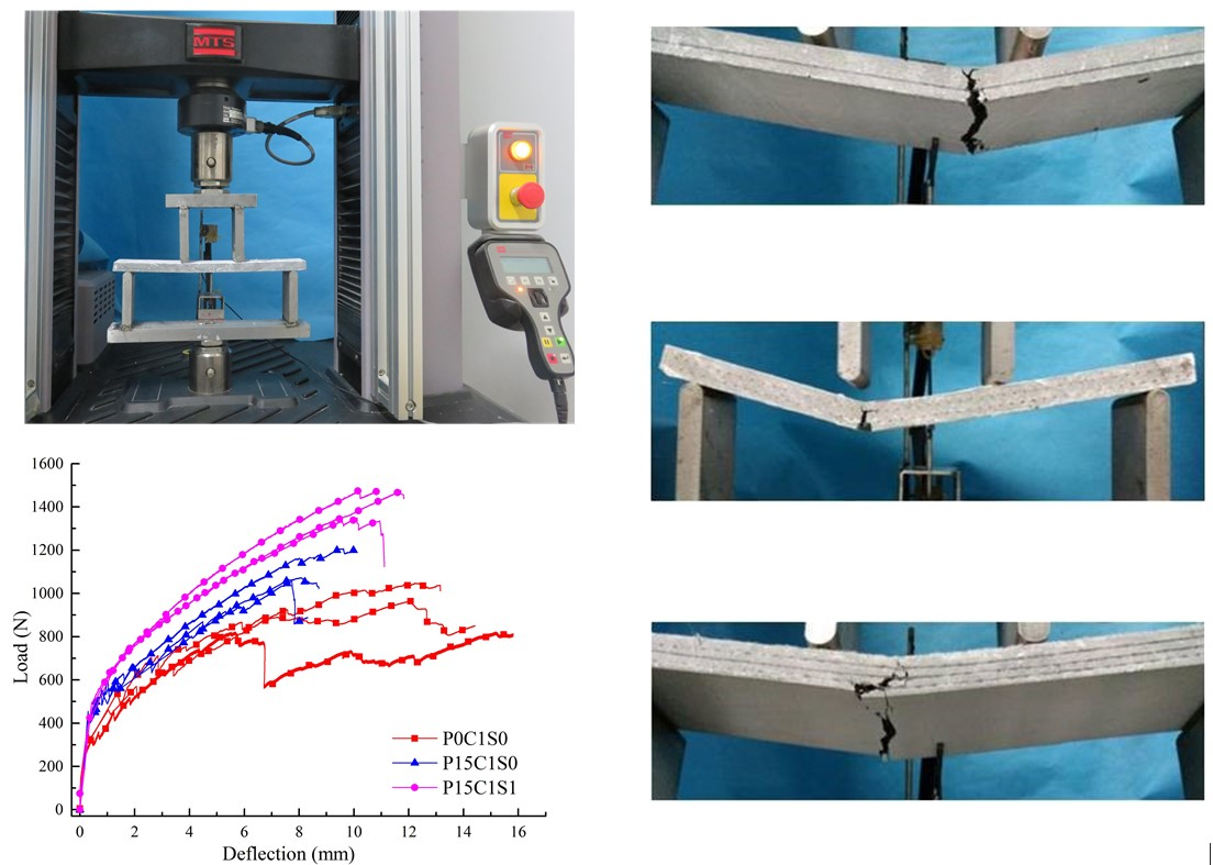
Figure 19 and
Table 6 summarized the experimental data of the prestressed TRC specimens. In
Figure 20, the first-crack and ultimate stresses of the corresponding specimens were compared. As shown in
Figure 19, prestress on the textile improved the bearing capacity of the TRC specimens and reduced the ultimate deflection. However, the bearing capacity of the prestressed TRC specimens was further improved, and the deforming capacity was enhanced due to the addition of steel fibres. In
Figure 20 and
Table 6, the first-crack stresses of P15C1S0 and P15C1S1 increased by 36.2% and 49.4%, respectively, compared with those of P0C1S0, and the increases in the ultimate stress were 18% and 51.9%. The first-crack stresses of P15C2S0 and P15C2S1 increased by 40.5% and 74.8%, respectively, compared with those of P0C2S0, and the corresponding increases in the ultimate stress were 13.4% and 71.2%. The first-crack stresses of P15C3S0 and P15C3S1 increased by 45.9% and 169.4%, respectively, compared with those of P0C3S0, and the corresponding increases in the ultimate stress were 16.2% and 79.1%.
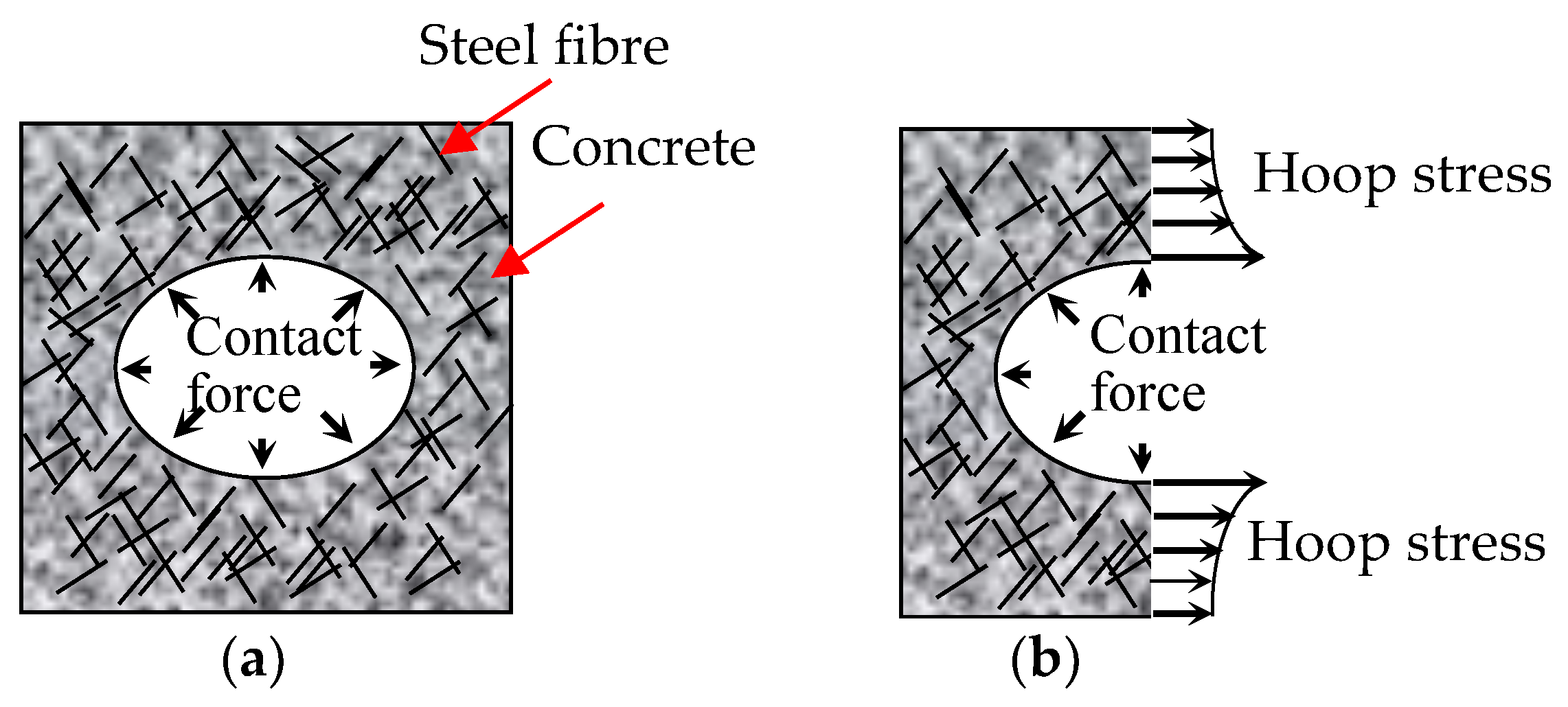
The comparison of data above indicated that the prestress on textile improved the first-crack and ultimate stresses of the TRC specimens, and the improvement on the first-crack stress was more pronounced. The release of the pre-tension on both ends of the textile provided the matrix initial compressive stress during the manufacture of the prestressed TRC plates, and the initial compressive stress on the matrix should be offset before cracking. Thus, the first-crack stress was increased by the prestress. In addition, the prestress brought about the effects of Poisson’s ratio. The warp yarns possessed a certain retraction after the release of the pre-tension on the textile. The cross section of yarns increases due to effect of Poisson’s ratio, thus the warp yarns squeezes the surrounding cementitious matrix, as depicted in
Figure 21a. Therefore, the interfacial friction, that is, bond performance, between the textile and matrix improved, and the tensile strength of the textile was better used [
24,
25]. However, prestress reduced the deforming capacity of the TRC specimens, thereby reducing the ultimate deflection. For a prestressed specimen, the textile obtained a certain initial strain before testing. The ultimate tensile strain of the textile was constant. Hence, the maximal deformation of the bottom textile decreased due to the initial strain of the textile, thereby reducing the ultimate deflection of the TRC specimens. The increase in the first-crack stress due to prestress was particularly pronounced with the increase in textile layers. The initial compressive stress on the matrix increased with more textile layers in the specimens, hence higher tensile stress was required. Adding 1% volume content of steel fibres into the prestressed TRC specimens could further improve the first-crack and ultimate stresses.
Table 5 showed that the effect of the prestress on the first-crack stress was more pronounced than that on the ultimate stress, and the effect of the steel fibres on the ultimate stress was more pronounced than that on the first-crack stress.
Figure 22 demonstrates the cracking patterns of the prestressed TRC specimens. The specimens exhibited multiple cracking behaviour, but the crack numbers of P15C1S0, P15C2S0, and P15C3S0 were less than those of the non-prestressed specimens. With regard to P15C1S1, P15C2S1, and P15C3S1, the prestress combined with steel fibres further improved the interfacial bonding performance between the textile and matrix. In addition, the steel fibres considerably restrained the propagation of cracks and increased the ultimate deflection of the specimens. Therefore, the crack number of the specimens increased and the average crack spacing was reduced.
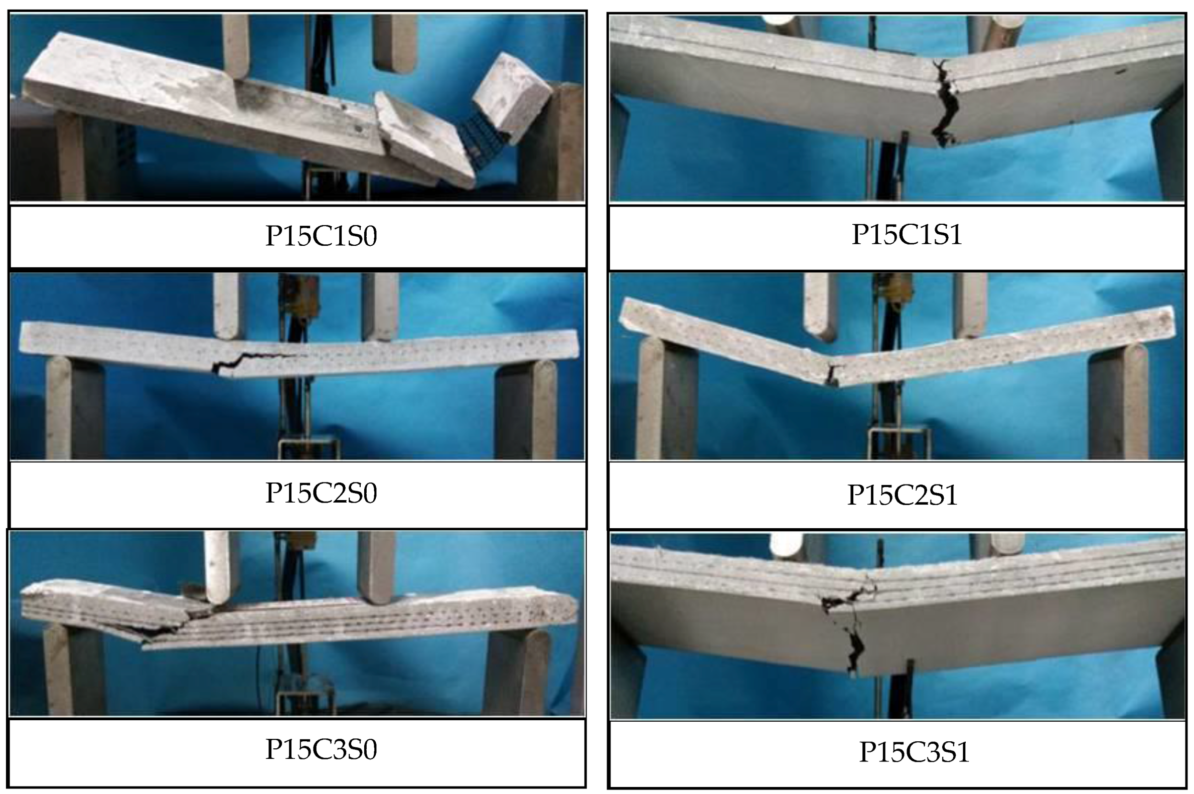
The failure modes of the prestressed TRC specimens are shown in
Figure 23. Although the prestress on the textiles could improve the matrix-textile interfacial bonding performance of P15C1S0, P15C2S0, and P15C3S0, the failure modes of the prestressed specimens were similar with those of the non-prestressed ones. The bottom textile was broken at failure for P15C1S1, P15C2S1, and P15C3S1, and debonding in the matrix-textile interface and oblique cracks in the shear-bending zone could not be observed. The matrix with steel fibres could better bear the circumferential stress caused by the transversal expansion of the warp yarns, as depicted in
Figure 21b. Therefore, the friction between the textile and matrix were effectively improved. The failure modes above indicated that the steel fibres could further improve the matrix-textile interfacial bonding performance, leading to the enhancement on the flexural and shear behaviour of the TRC specimens.


