In-Situ Bubble Stretching Assisted Melt Extrusion for the Preparation of HDPE/UHMWPE/CF Composites

 ,
,
Abstract
:
1. Introduction
2. Experimental
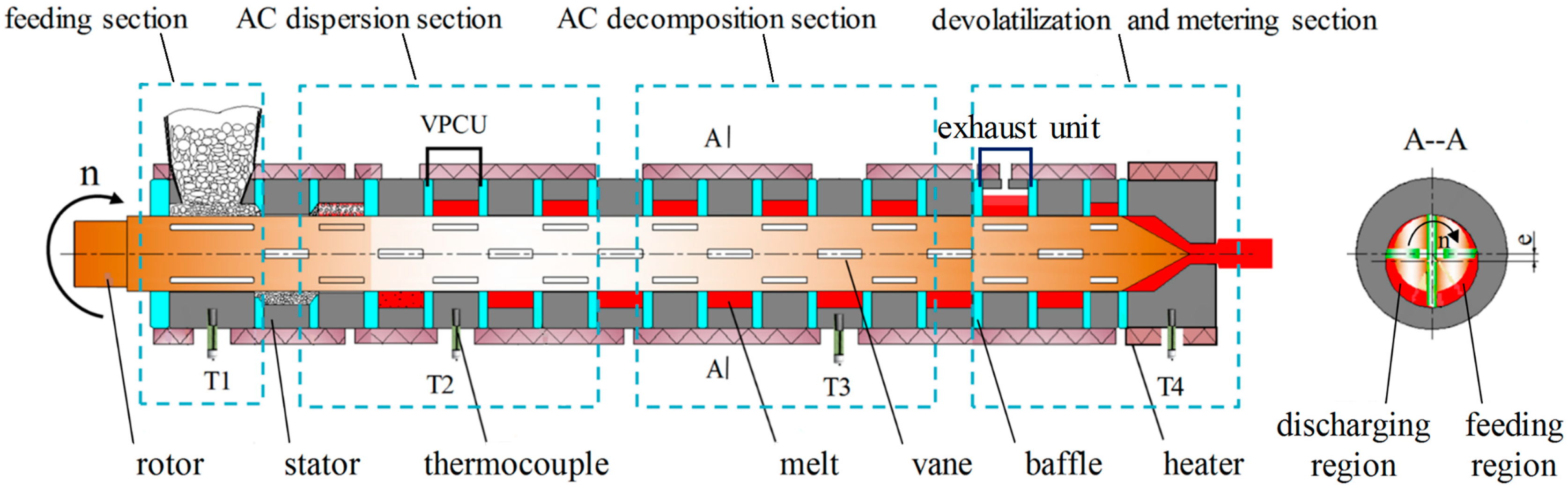
2.1. Vane Extruder
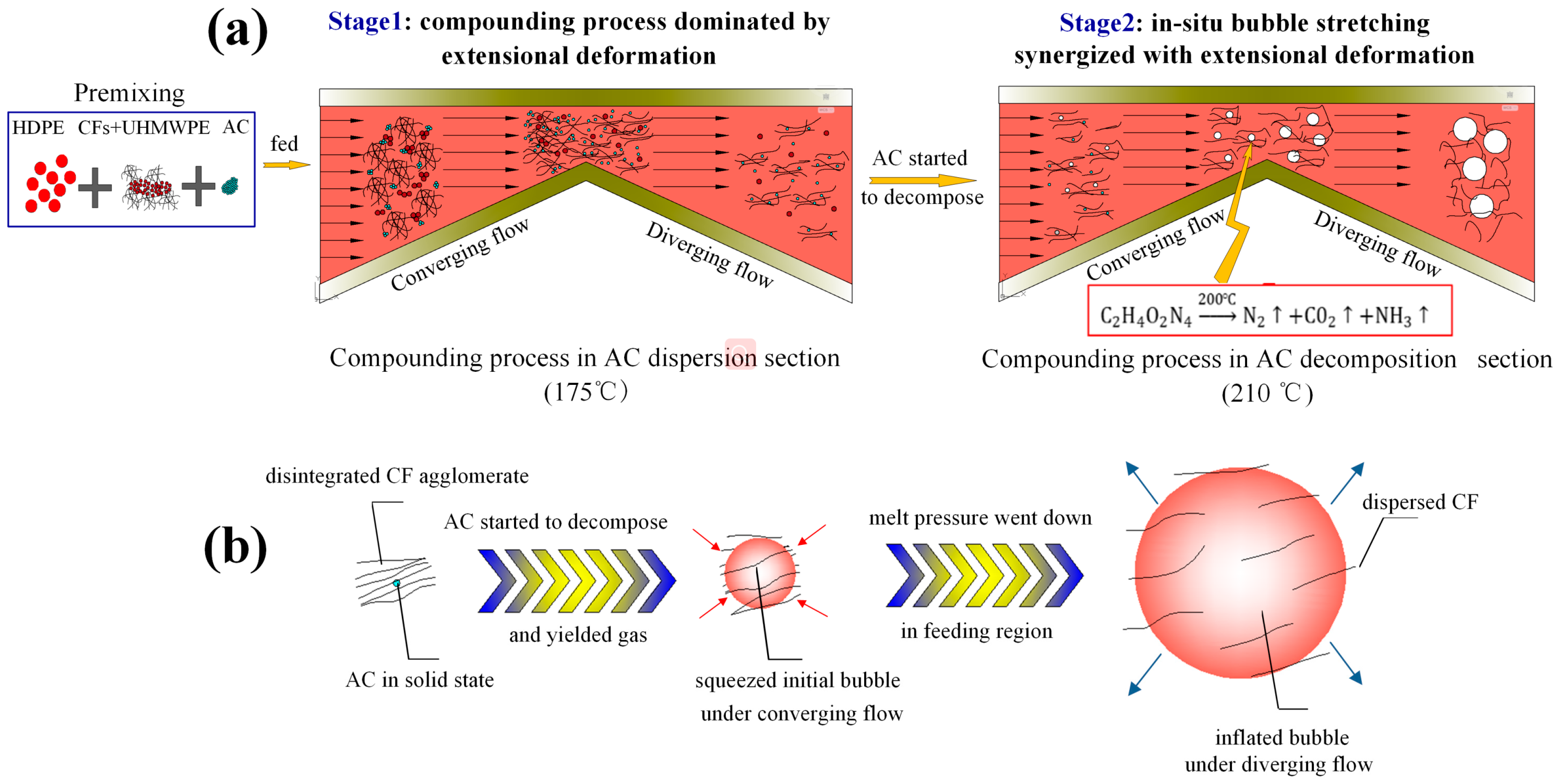
2.2. Compounding Process under Synergy of Extensional Deformation and ISBS
2.2.1. Feeding
2.2.2. Compounding Dominated by Extensional Deformation
2.2.3. Compounding under Synergy of Extensional Deformation and ISBS
2.2.4. Devolatilization and Metering
2.3. Materials
2.4. Sample Preparation
2.5. Characterization
2.5.1. Morphology Observation
2.5.2. Differential Scanning Calorimetry (DSC)
2.5.3. Thermogravimetric Analysis (TGA)
2.5.4. Rheological Properties Analysis
2.5.5. Mechanical Test
3. Results and Discussion
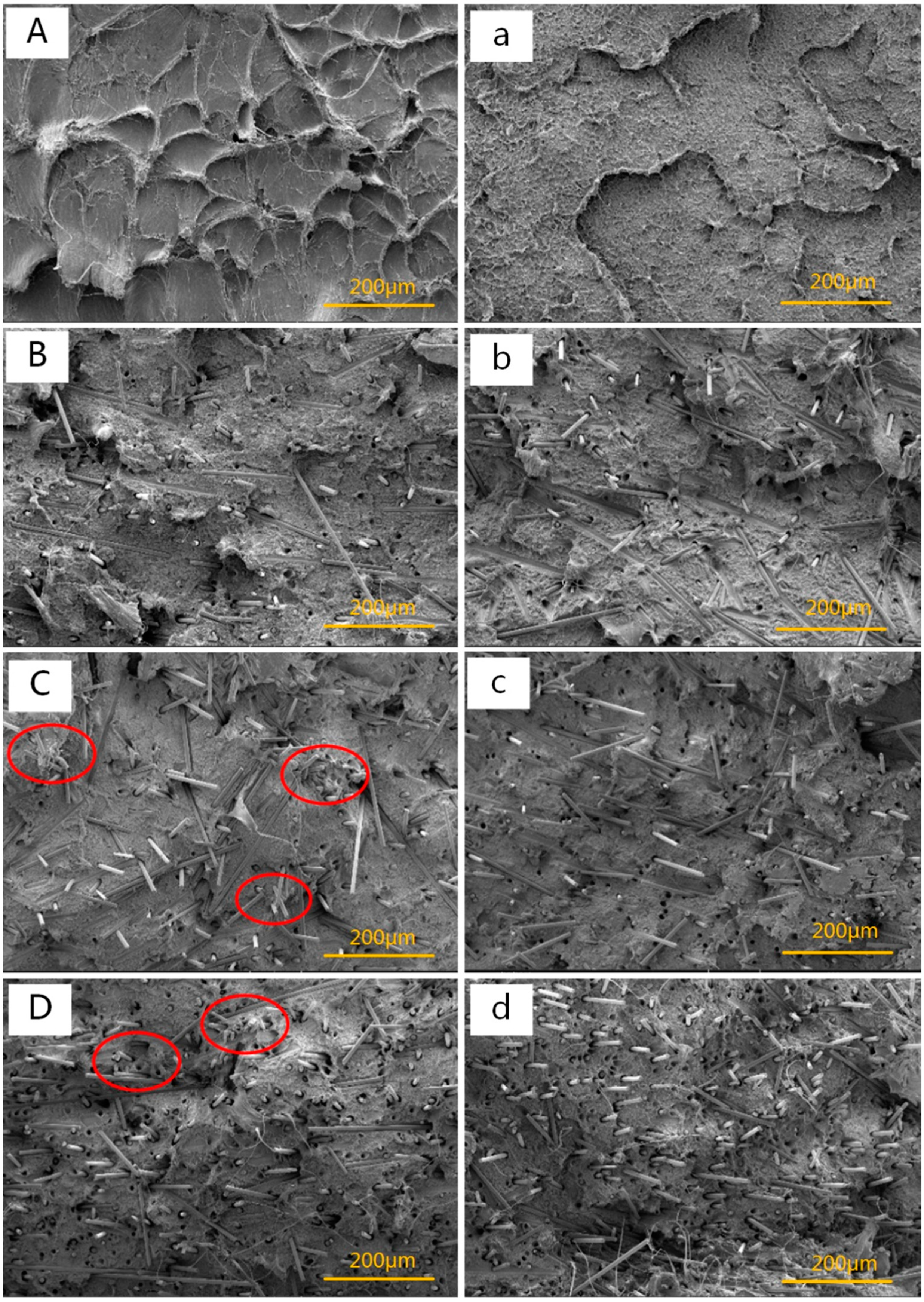
3.1. Morphology Observation
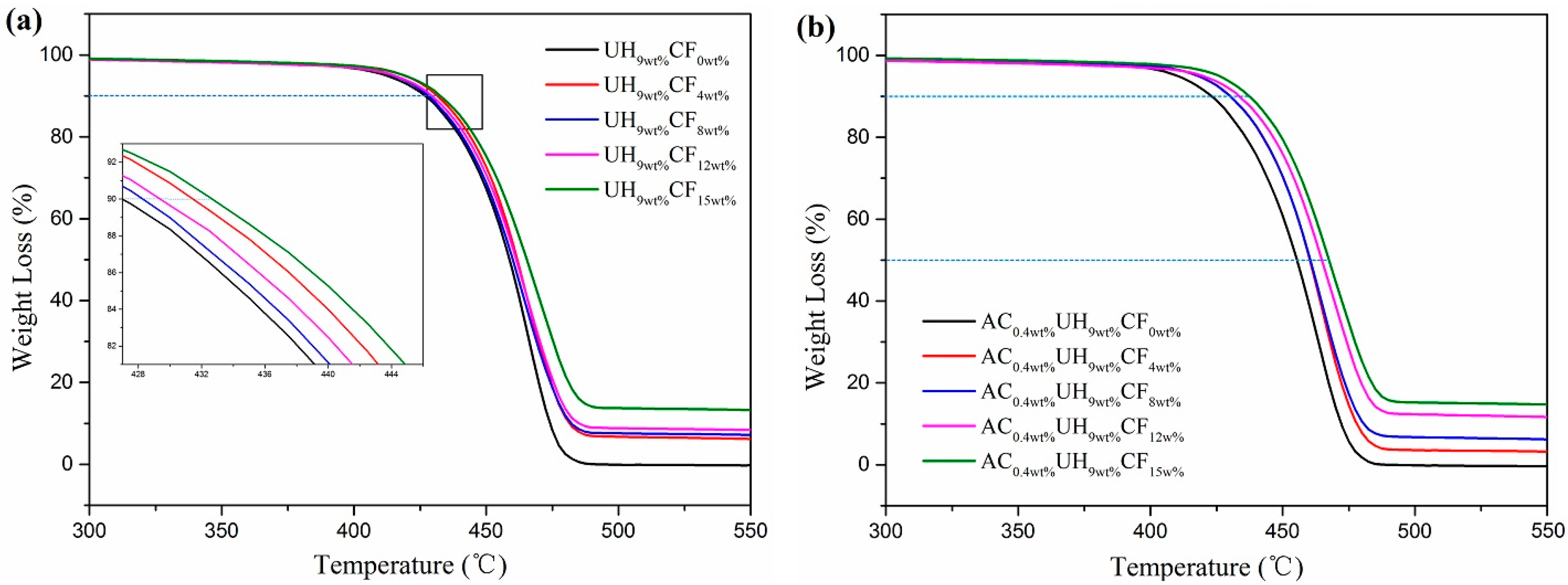
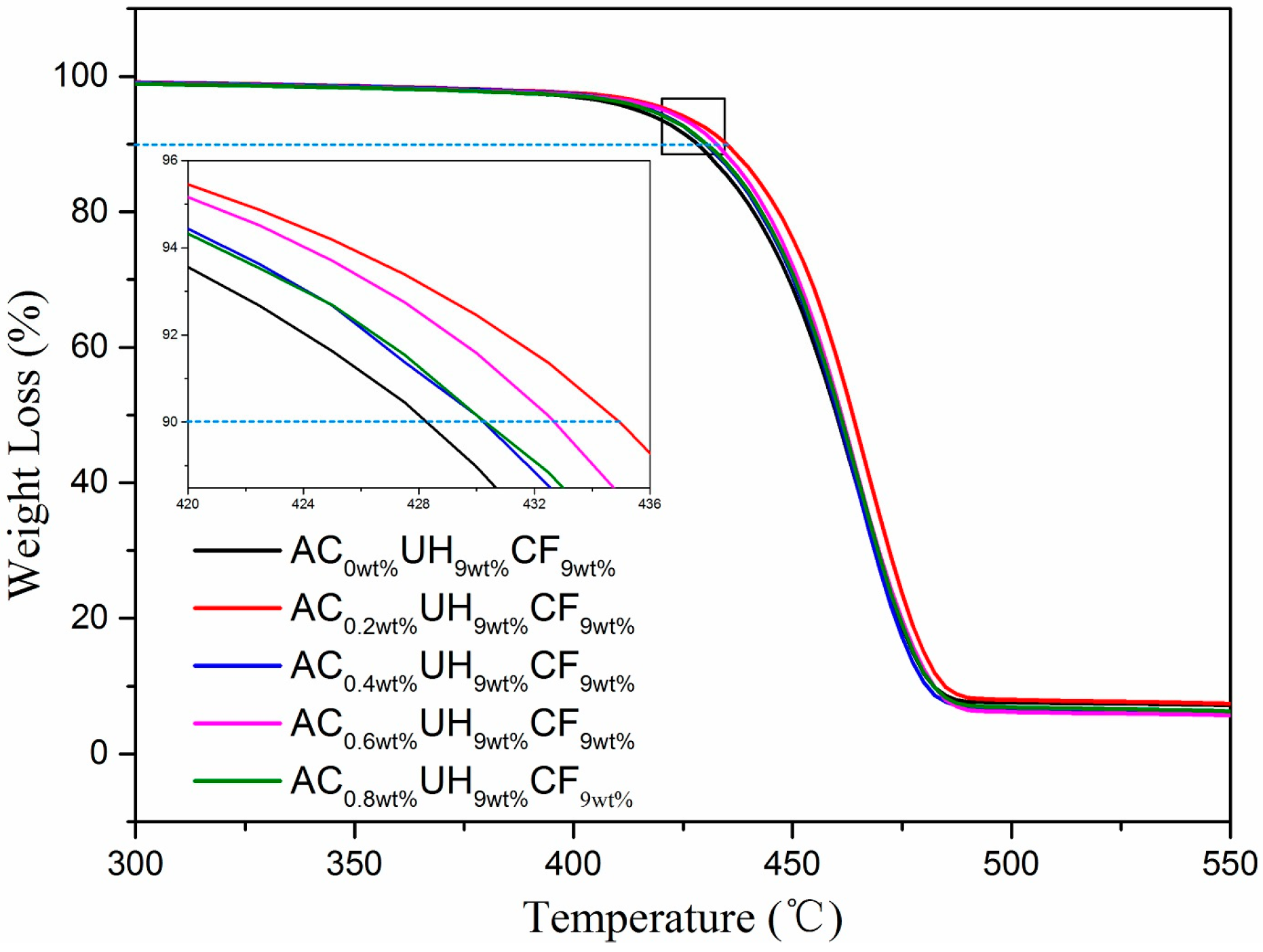
3.2. Thermogravimetric Analysis
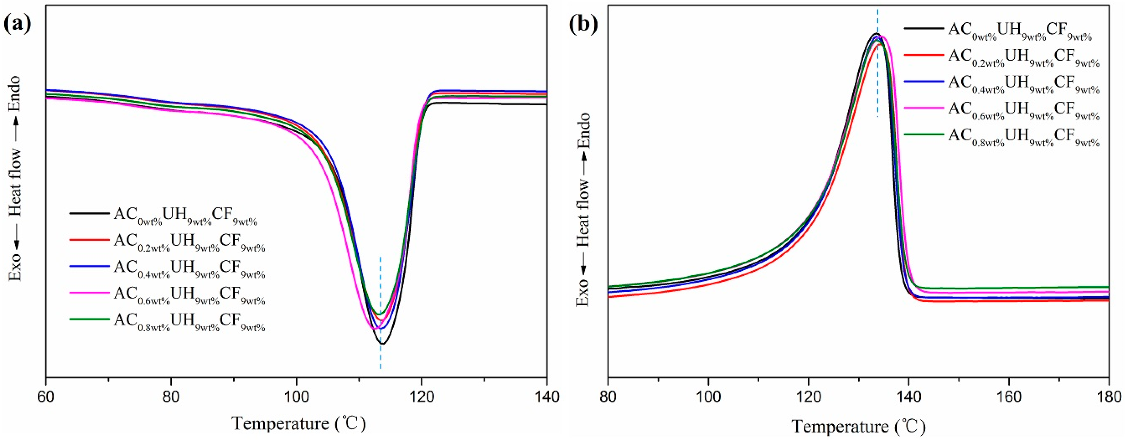
3.3. DSC Analysis
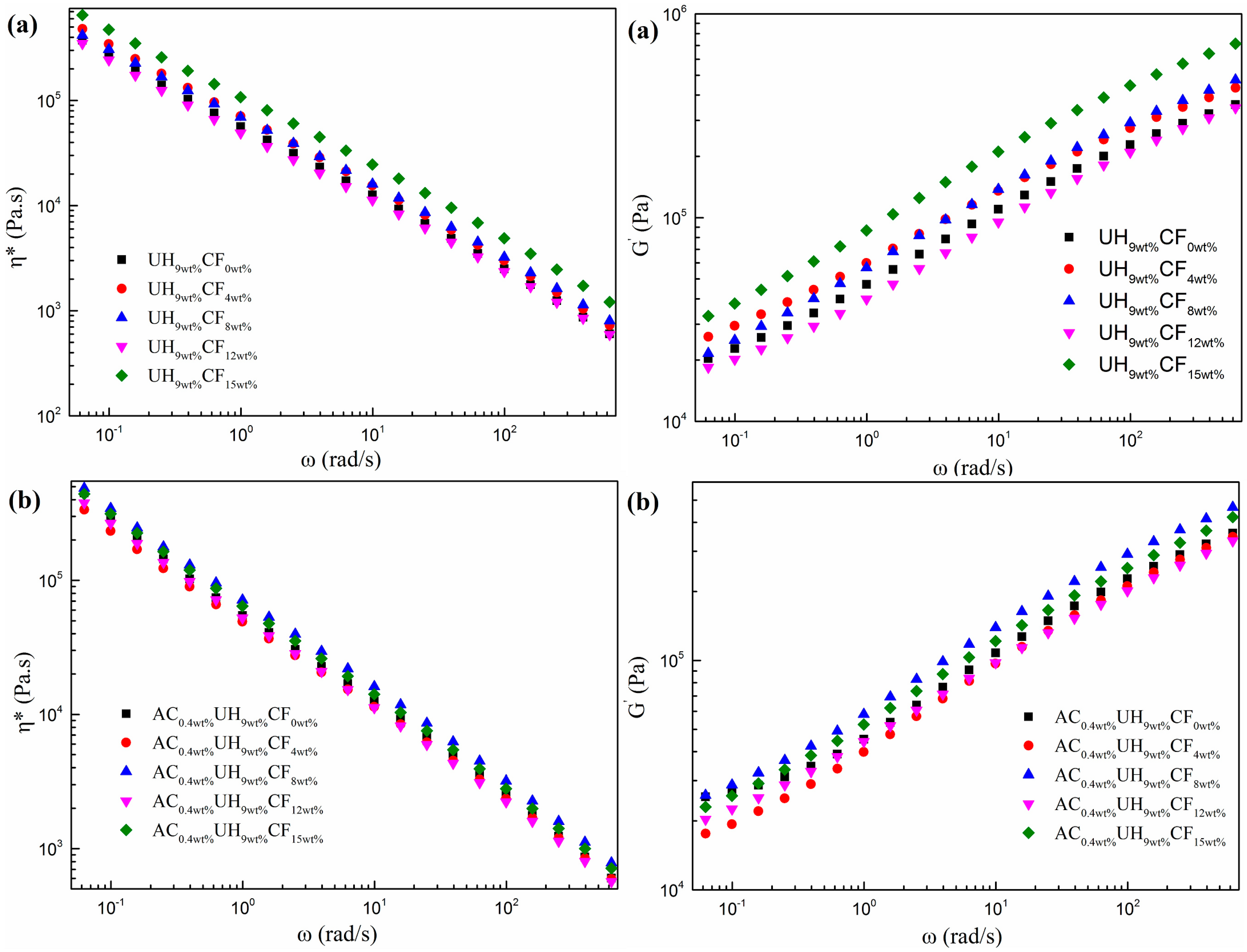
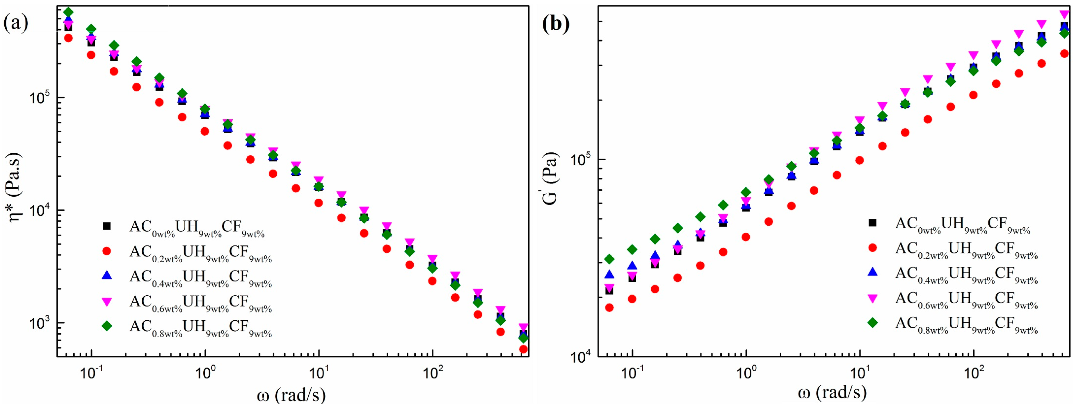
3.4. Rheological Properties Analysis
3.5. Mechanical Properties
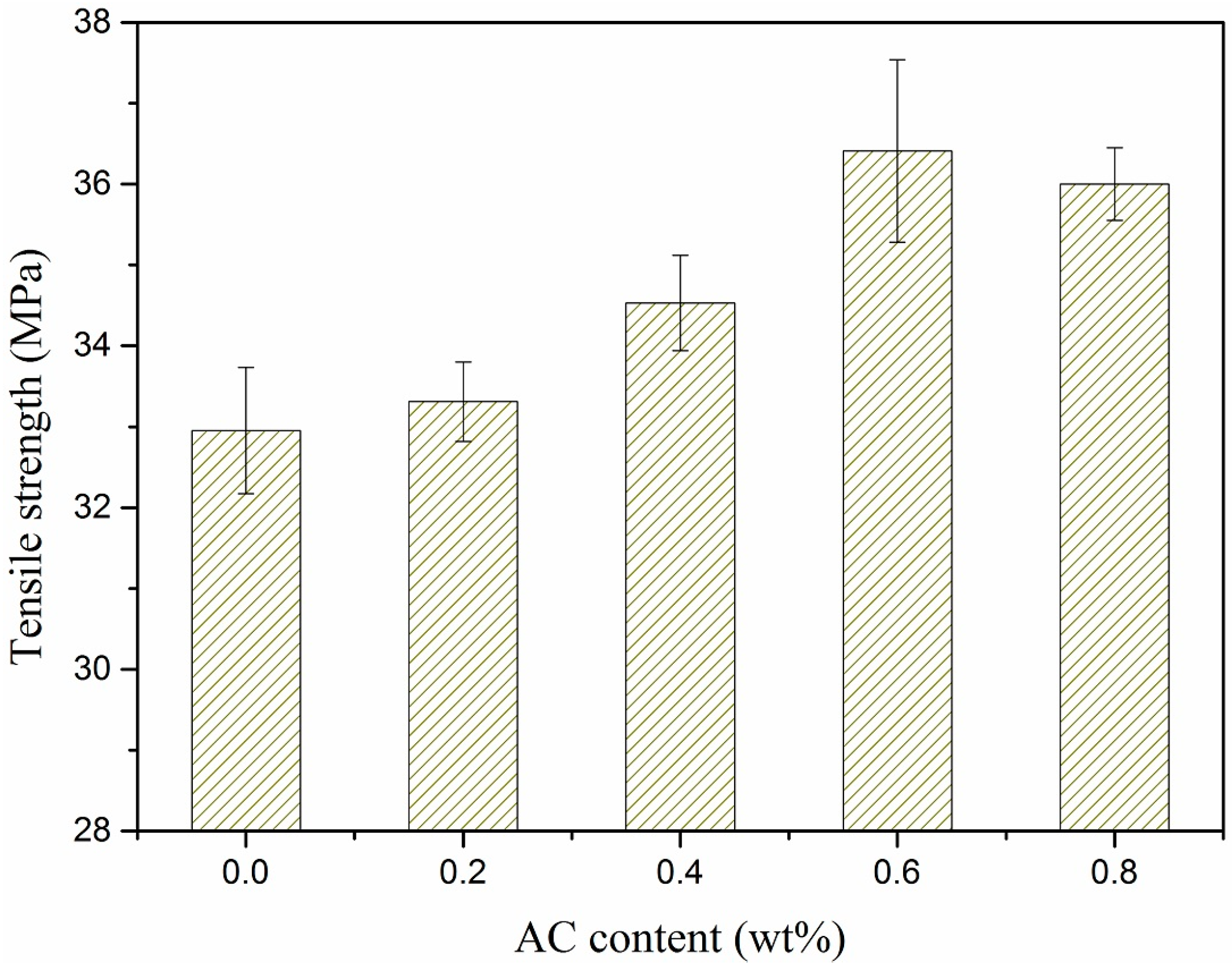
3.5.1. Tensile Strength
3.5.2. Impact Strength
4. Conclusions
Author Contributions
Funding
Conflicts of Interest
References
- Sewda, K.; Maiti, S.N. Dynamic mechanical properties of high density polyethylene and teak wood flour composites. Polym. Bull. 2013, 70, 2657–2674. [Google Scholar] [CrossRef]
- Xiang, F.M.; Wu, J.; Liu, L.; Huang, T.; Wang, Y.; Chen, C.; Peng, Y.; Jiang, C.X.; Zhou, Z.W. Largely enhanced ductility of immiscible high density polyethylene/polyamide 6 blends via nano-bridge effect of functionalized multiwalled carbon nanotubes. Polym. Adv. Technol. 2011, 22, 2533–2542. [Google Scholar] [CrossRef]
- Zhou, Y.; Yin, B.; Li, L.P.; Yang, M.B.; Feng, J.M. Characterization of PP/EPDM/HDPE Ternary Blends: The Role of Two EPDM with Different Viscosity and Processing Method. Polym. Plast. Technol. 2012, 51, 983–990. [Google Scholar] [CrossRef]
- Jaggi, H.S.; Satapathy, B.K.; Ray, A.R. Viscoelastic properties correlations to morphological and mechanical response of HDPE/UHMWPE blends. J. Polym. Res. 2014, 21, 482. [Google Scholar] [CrossRef]
- Matar, M.; Azambre, B.; Cochez, M.; Vahabi, H.; Fradet, F. Influence of modified mesoporous silica SBA-15 on the flammability of intumescent high-density polyethylene. Polym. Adv. Technol. 2016, 27, 1363–1375. [Google Scholar] [CrossRef]
- Sun, P.; Qian, T.Y.; Ji, X.Y.; Wu, C.; Yan, Y.S.; Qi, R.R. HDPE/UHMWPE composite foams prepared by compression molding with optimized foaming capacity and mechanical properties. J. Appl. Polym. Sci. 2018, 135, 46768. [Google Scholar] [CrossRef]
- Hu, L.; Leclair, E.; Diez, C.; Vuillaume, P.Y. Enhancement of thermal and mechanical properties of high density polyethylene using commercial clays. Int. J. Plast. Technol. 2017, 21, 313–325. [Google Scholar] [CrossRef]
- Savas, L.A.; Tayfun, U.; Dogan, M. The use of polyethylene copolymers as compatibilizers in carbon fiber reinforced high density polyethylene composites. Compos. Part B Eng. 2016, 99, 188–195. [Google Scholar] [CrossRef]
- Wang, Y.; Xia, L.; Xin, Z.X. Triple shape memory effect of foamed natural Eucommia ulmoides gum/high-density polyethylene composites. Polym. Adv. Technol. 2018, 29, 190–197. [Google Scholar] [CrossRef]
- Xiong, C.; Qi, R.R.; Gong, W.J. The preparation and properties of wood flour/high density polyethylene composites by in-situ reaction extrusion. Polym. Adv. Technol. 2009, 20, 273–279. [Google Scholar] [CrossRef]
- Kahar, A.W.M.; Ismail, H.; Hamid, A.A. The correlation between crosslink density and thermal properties of high-density polyethylene/natural rubber/thermoplastic tapioca starch blends prepared via dynamic vulcanisation approach. J. Therm. Anal. Calorim. 2016, 123, 301–308. [Google Scholar] [CrossRef]
- Xu, L.; Chen, C.; Zhong, G.J.; Lei, J.; Xu, J.Z.; Hsiao, B.S. Tuning the Superstructure of Ultrahigh-Molecular-Weight Polyethylene/Low-Molecular-Weight Polyethylene Blend for Artificial Joint Application. ACS Appl. Mater. Interfac. 2012, 4, 1521–1529. [Google Scholar] [CrossRef] [PubMed]
- Fu, J.; Ghali, B.W.; Lozynsky, A.J.; Oral, E.; Muratoglu, O.K. Wear resistant UHMWPE with high toughness by high temperature melting and subsequent radiation cross-linking. Polymer 2011, 52, 1155–1162. [Google Scholar] [CrossRef]
- Aguilar, M.; Martín, S.; Vega, J.F.; Muñoz-Escalona, A.; Martínez-Salazar, J. Processability of a metallocene-catalyzed linear PE improved by blending with a small amount of UHMWPE. J. Polym. Sci. Pol. Phys. 2005, 43, 2963–2971. [Google Scholar] [CrossRef]
- Xue, Y.; Wu, W.; Jacobs, O.; Schadel, B. Tribological behaviour of UHMWPE/HDPE blends reinforced with multi-wall carbon nanotubes. Polym. Test. 2006, 25, 221–229. [Google Scholar] [CrossRef]
- Alon, Y.; Marom, G. On the beta transition in high density polyethylene: The effect of transcrystallinity. Macromol. Rapid. Comm. 2004, 25, 1387–1391. [Google Scholar] [CrossRef]
- Bartels, C.R.; Crist, B.; Graessley, W.W. Self-diffusion coefficient in melts of linear polymers: Chain length and temperature dependence for hydrogenated polybutadiene. Macromolecules 1984, 17, 2702–2708. [Google Scholar] [CrossRef]
- Zhang, J.G. The mechanical and tribological behaviors of LMPB-g-MAH-treated carbon fiber-filled SBR composite. J. Thermoplast. Compos. Mater. 2014, 27, 611–619. [Google Scholar] [CrossRef]
- Sharma, M.; Bijwe, J. Influence of fiber-matrix adhesion and operating parameters on sliding wear performance of carbon fabric polyethersulphone composites. Wear 2011, 271, 2919–2927. [Google Scholar] [CrossRef]
- Dlamini, D.S.; Mishra, S.B.; Mishra, A.K.; Mamba, B.B. Comparative studies of the morphological and thermal properties of clay/polymer nanocomposites synthesized via melt blending and modified solution blending methods. J. Compos. Mater. 2011, 45, 2211–2216. [Google Scholar] [CrossRef]
- Chen, Y.; Nie, X.; Zhou, S.T.; Zou, H.W.; Liang, M.; Liu, P.B. Investigations of environmental stress cracking resistance of HDPE/UHMWPE and LDPE/UHMWPE blends. J. Polym. Res. 2013, 20, 141. [Google Scholar] [CrossRef]
- Shokoohi, S.; Arefazar, A.; Naderi, G. Compatibilized PP/EPDM/PA6 ternary blends: Extended morphological studies. Polym. Adv. Technol. 2012, 23, 418–424. [Google Scholar] [CrossRef]
- Miroshnikov, Y.P.; Egorov, A.K.; Egorova, M.V. Measuring of Coalescence in Polymer Melt Blends Flowing Through Converging Channels. J. Appl. Polym. Sci. 2011, 120, 2724–2733. [Google Scholar] [CrossRef]
- Wang, C.; Ying, S. Batch foaming of short carbon fiber reinforced polypropylene composites. Fiber Polym. 2013, 14, 815–821. [Google Scholar] [CrossRef]
- Scott, C.E.; Macosko, C.W. Model experiments concerning morphology development during the initial stages of polymer blending. Polym. Bull. 1991, 26, 341–348. [Google Scholar] [CrossRef]
- Qu, J.P. Method and a Device for Plasticizing and Transporting Polymer Material Based on Elongation Rheology. U.S. Patent 8,573,828, 5 November 2013. [Google Scholar]
- Yin, X.C.; Yang, Z.T.; Feng, Y.H.; Qu, J.P.; He, G.J. Mixing method and device by virtue of biaxial tension deformation synergetic effect. C.N. Patent 103,770,231, 5 July 2014. [Google Scholar]
- Zou, W.; Chen, R.Y.; Wu, C.R.; Qu, J.P. Influence of process parameters on property of PP/EPDM blends prepared by a novel vane extruder. J. Polym. Eng. 2016, 36, 899–908. [Google Scholar] [CrossRef]
- Huang, Z.X.; Zhou, L.Y.; Zhang, G.Z.; Qu, J.P.; He, H.Z. Study on the properties of polyethylene/montmorillonite nanocomposites prepared by a novel vane mixer. J. Appl. Polym. Sci. 2015, 132, 42600. [Google Scholar] [CrossRef]
- Yin, X.C.; Li, S.; He, G.J.; Feng, Y.H.; Wen, J.S. Preparation and characterization of CNTs/UHMWPE nanocomposites via a novel mixer under synergy of ultrasonic wave and extensional deformation. Ultrason. Sonochem. 2018, 43, 15–22. [Google Scholar] [CrossRef]
- Wu, D.M.; Meng, Q.Y.; Liu, Y.; Ding, Y.M.; Chen, W.H.; Xu, H.; Ren, D.Y. In situ bubble-stretching dispersion mechanism for additives in polymers. J. Polym. Sci. Pol. Phys. 2003, 41, 1051–1058. [Google Scholar] [CrossRef]
- Chen, Z.G.; Liu, S.M.; Yan, S.J.; Shu, X.; Yuan, Y.C.; Huang, H.H.; Zhao, J.Q. Overall improvement in dielectric and mechanical properties of porous graphene fluoroxide/polyimide nanocomposite films via bubble-stretching approach. Mater. Des. 2017, 117, 150–156. [Google Scholar] [CrossRef]
- Yang, Z.T.; Li, Q.S.; Tong, Y.Z.; Wu, T.; Feng, Y.H. Homogeneous dispersion of multiwalled carbon nanotubes via in situ bubble stretching and synergistic cyclic volume stretching for conductive LDPE/MWCNTs nanocomposites. Polym. Eng. Sci. 2019, 59, 2072–2081. [Google Scholar] [CrossRef]
- Yin, X.C.; Li, Y.; Cheng, D.; Feng, Y.H.; He, G.J. Improvements in thermal conductivity and mechanical properties of HDPE/nano-SiC composites by the synergetic effect of extensional deformation and ISBS. J. Appl. Polym. Sci. 2019, 136, 47648. [Google Scholar] [CrossRef]
- Jia, S.; Qu, J.P.; Wu, C.; Liu, W.; Chen, R.; Zhai, S.; Huang, Z.; Chen, F. Novel Dynamic Elongational Flow Procedure for Reinforcing Strong, Tough, Thermally Stable Polypropylene/Thermoplastic Polyurethane Blends. Langmuir 2013, 29, 13509–13517. [Google Scholar] [CrossRef] [PubMed]
- Qu, J.P.; Zhao, X.Q.; Li, J.B.; Cai, S.Q. Power consumption in the compacting process of polymer particulate solids in a vane extruder. J. Appl. Polym. Sci. 2013, 127, 3923–3932. [Google Scholar] [CrossRef]
- Hussain, Y.A.; Grant, C.S. Ibuprofen impregnation into submicron polymeric films in supercritical carbon dioxide. J. Supercrt. Fluid. 2012, 71, 127–135. [Google Scholar] [CrossRef]
- Zhang, Q.H.; Lippits, D.R.; Rastogi, S. Dispersion and rheological aspects of SWNTs in ultrahigh molecular weight polyethylene. Macromolecules 2006, 39, 658–666. [Google Scholar] [CrossRef]
- Vega, J.F.; da Silva, Y.; Vicente-Alique, E.; Nunez-Ramirez, R.; Trujillo, M.; Arnal, M.L.; Muller, A.J.; Dubois, P.; Martinez-Salazar, J. Influence of Chain Branching and Molecular Weight on Melt Rheology and Crystallization of Polyethylene/Carbon Nanotube Nanocomposites. Macromolecules 2014, 47, 5668–5681. [Google Scholar] [CrossRef]
- Bryk, M.T. Degradation of Filled Polymers; Ellis Horwood: New York, NY, USA, 1991; p. 71. [Google Scholar]
- Kashiwagi, T.; Du, F.; Douglas, J.F. Nanoparticle networks reduce the flammability of polymer nanocomposites. Nat. mater. 2005, 4, 928–933. [Google Scholar] [CrossRef]
- Yoo, H.J.; Han, C.D. Oscillatory behavior of a gas bubble growing (or collapsing) in viscoelastic liquids. Aiche J. 1982, 28, 1002–1009. [Google Scholar] [CrossRef]
- Cai, L.F.; Huang, X.B.; Rong, M.Z.; Ruan, W.H.; Zhang, M.Q. Effect of grafted polymeric foaming agent on the structure and properties of nano-silica/polypropylene composites. Polymer 2006, 47, 7043–7050. [Google Scholar] [CrossRef]
- Sarasini, F.; Tirillò, J.; Sergi, C.; Seghini, M.C.; Cozzarini, L.; Graupner, N. Effect of basalt fibre hybridisation and sizing removal on mechanical and thermal properties of hemp fibre reinforced HDPE composites. Compos. Struct. 2018, 188, 394–406. [Google Scholar] [CrossRef] [Green Version]
- Yin, C.L.; Liu, Z.Y.; Gao, Y.J.; Yang, M.B. Effect of compounding procedure on morphology and crystallization behavior of isotactic polypropylene/high-density polyethylene/carbon black ternary composites. Polym. Adv. Technol. 2012, 23, 1112–1120. [Google Scholar] [CrossRef]
- Kyu, T.; Vadhar, P. Cocrystallization and Miscibility Studies of Blends of Ultrahigh Molecular Weight Polyethylene with Conventional Polyethylenes. J. Appl. Polym. Sci. 1986, 32, 5575–5584. [Google Scholar] [CrossRef]
- Jacobson, K. Oxidation of ultra high molecular weight polyethylene (UHMWPE) part 1: Interpretation of the chemiluminescence curve recorded during thermal oxidation. Polym. Degrad. Stabil. 2006, 91, 2126–2132. [Google Scholar] [CrossRef]
- Ren, X.; Wang, X.Q.; Sui, G.; Zhong, W.H.; Fuqua, M.A.; Ulven, C.A. Effects of Carbon Nanofibers on Crystalline Structures and Properties of Ultrahigh Molecular Weight Polyethylene Blend Fabricated Using Twin-Screw Extrusion. J. Appl. Polym. Sci. 2007, 107, 2837–2845. [Google Scholar] [CrossRef]
- Lozano, K.; Barrera, E.V. Nanofiber-reinforced thermoplastic composites. I. Thermoanalytical and mechanical analyses. J. Appl. Polym. Sci. 2001, 79, 125–133. [Google Scholar] [CrossRef]
- Li, F.; Liu, Y.; Qu, C.B.; Xiao, H.M.; Hua, Y.; Sui, G.X.; Fu, S.Y. Enhanced mechanical properties of short carbon fiber reinforced polyethersulfone composites by graphene oxide coating. Polymer 2015, 59, 155–165. [Google Scholar] [CrossRef]
- Huang, J.T.; Lu, X.; Zhang, G.Z.; Qu, J.P. Study on the rheological, thermal and mechanical properties of thermoplastic polyurethane/poly (butylene terephthalate) blends. Polym. Test. 2014, 36, 69–74. [Google Scholar] [CrossRef]
- Karsli, N.G.; Aytac, A. Tensile and thermomechanical properties of short carbon fiber reinforced polyamide 6 composites. Compos. Part B-Eng. 2013, 51, 270–275. [Google Scholar] [CrossRef]
- Jacob, M.; Francis, B.; Thomas, S.; Varughese, K.T. Dynamical mechanical analysis of sisal/oil palm hybrid fiber-reinforced natural rubber composites. Polym. Composite. 2006, 27, 671–680. [Google Scholar] [CrossRef]
- Li, W.; Guan, C.; Xu, J.; Mu, J.S.; Gong, D.R.; Chen, Z.R.; Zhou, Q. Disentangled UHMWPE/POSS nanocomposites prepared by ethylene in situ polymerization. Polymer 2014, 55, 1792–1798. [Google Scholar] [CrossRef]


| Samples | T10% (°C) | T50% (°C) | Tmax (°C) | Cr (%) |
|---|---|---|---|---|
| UH9wt%CF0wt% | 425.5 | 459.1 | 475.6 | 0.35 |
| AC0.4wt%UH9wt%CF0wt% | 423.2 | 455.8 | 475.9 | 0.43 |
| UH9wt%CF4wt% | 431.2 | 460.5 | 479.0 | 2.52 |
| AC0.4wt%UH9wt%CF4wt% | 430.2 | 459.8 | 478.3 | 2.88 |
| UH9wt%CF8wt% | 428.6 | 460.9 | 480.3 | 6.70 |
| AC0.4wt%UH9wt%CF8wt% | 430.1 | 459.2 | 478.2 | 6.57 |
| UH9wt%CF12wt% | 429.4 | 461.6 | 480.7 | 10.99 |
| AC0.4wt%UH9wt%CF12w% | 433.9 | 462.2 | 482.9 | 10.96 |
| UH9wt%CF15wt% | 432.5 | 465.0 | 484.1 | 14.79 |
| AC0.4wt%UH9wt%CF15w% | 437.4 | 464.0 | 484.2 | 14.19 |
| Samples | T10% (°C) | T50% (°C) | Tmax (°C) | Cr (%) |
|---|---|---|---|---|
| AC0wt%UH9wt%CF9wt% | 428.6 | 459.9 | 480.3 | 6.70 |
| AC0.2wt%UH9wt%CF9wt% | 434.9 | 462.3 | 482.2 | 6.12 |
| AC0.4wt%UH9wt%CF9wt% | 430.1 | 459.2 | 478.2 | 6.57 |
| AC0.6wt%UH9wt%CF9wt% | 432.6 | 460.1 | 480.8 | 6.17 |
| AC0.8wt%UH9wt%CF9wt% | 430.5 | 460.6 | 480.6 | 6.64 |
| Samples | Tc (°C) | Tm (°C) | ΔHm (J/g) | Xc (%) |
|---|---|---|---|---|
| UH9wt%CF0wt% | 112.0 | 134.7 | 176.1 | 60.1 |
| AC0.4wt%UH9wt%CF0wt% | 112.9 | 134.6 | 165.4 | 56.4 |
| UH9wt%CF4wt% | 113.9 | 132.7 | 174.9 | 62.2 |
| AC0.4wt%UH9wt%CF4wt% | 112.3 | 134.8 | 158.6 | 56.3 |
| UH9wt%CF8wt% | 113.8 | 133.7 | 155.6 | 57.7 |
| AC0.4wt%UH9wt%CF8wt% | 113.5 | 133.6 | 150.3 | 55.7 |
| UH9wt%CF12wt% | 112.7 | 135.4 | 154.1 | 59.7 |
| AC0.4wt%UH9wt%CF12wt% | 112.4 | 134.6 | 141.9 | 55.0 |
| UH9wt%CF15wt% | 113.2 | 134.6 | 152.1 | 60.0 |
| AC0.4wt%UH9wt%CF15wt% | 114.3 | 132.9 | 137.3 | 55.1 |
| Samples | Tc (°C) | Tm (°C) | ΔHm (J/g) | Xc (%) |
|---|---|---|---|---|
| AC0wt%UH9wt%CF9wt% | 113.8 | 133.7 | 155.6 | 57.7 |
| AC0.2wt%UH9wt%CF9wt% | 113.6 | 134.4 | 151.1 | 56.6 |
| AC0.4wt%UH9wt%CF9wt% | 113.5 | 133.6 | 150.3 | 56.4 |
| AC0.6wt%UH9wt%CF9wt% | 112.6 | 134.4 | 150.0 | 56.2 |
| AC0.8wt%UH9wt%CF9wt% | 113.2 | 133.6 | 150.6 | 56.5 |
© 2019 by the authors. Licensee MDPI, Basel, Switzerland. This article is an open access article distributed under the terms and conditions of the Creative Commons Attribution (CC BY) license (http://creativecommons.org/licenses/by/4.0/).
Share and Cite
Yin, X.; Yin, Y.; Cheng, D.; Feng, Y.; Zhang, G.; Wen, J. In-Situ Bubble Stretching Assisted Melt Extrusion for the Preparation of HDPE/UHMWPE/CF Composites. Polymers 2019, 11, 2054. https://doi.org/10.3390/polym11122054
Yin X, Yin Y, Cheng D, Feng Y, Zhang G, Wen J. In-Situ Bubble Stretching Assisted Melt Extrusion for the Preparation of HDPE/UHMWPE/CF Composites. Polymers. 2019; 11(12):2054. https://doi.org/10.3390/polym11122054
Chicago/Turabian StyleYin, Xiaochun, Youhua Yin, Di Cheng, Yanhong Feng, Guizhen Zhang, and Jinsong Wen. 2019. "In-Situ Bubble Stretching Assisted Melt Extrusion for the Preparation of HDPE/UHMWPE/CF Composites" Polymers 11, no. 12: 2054. https://doi.org/10.3390/polym11122054