Effect of a Dual Functional Polymer on the Electro-Optical Properties of Blue Phase Liquid Crystals

Abstract
:
1. Introduction
2. Materials and Methods
3. Results
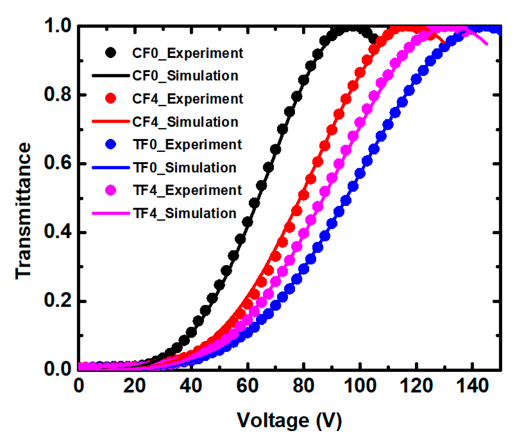
3.1. Kerr Effect
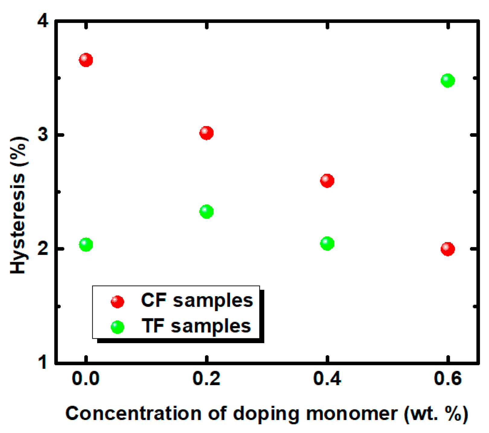
3.2. Hysteresis
3.3. Residual Birefringence
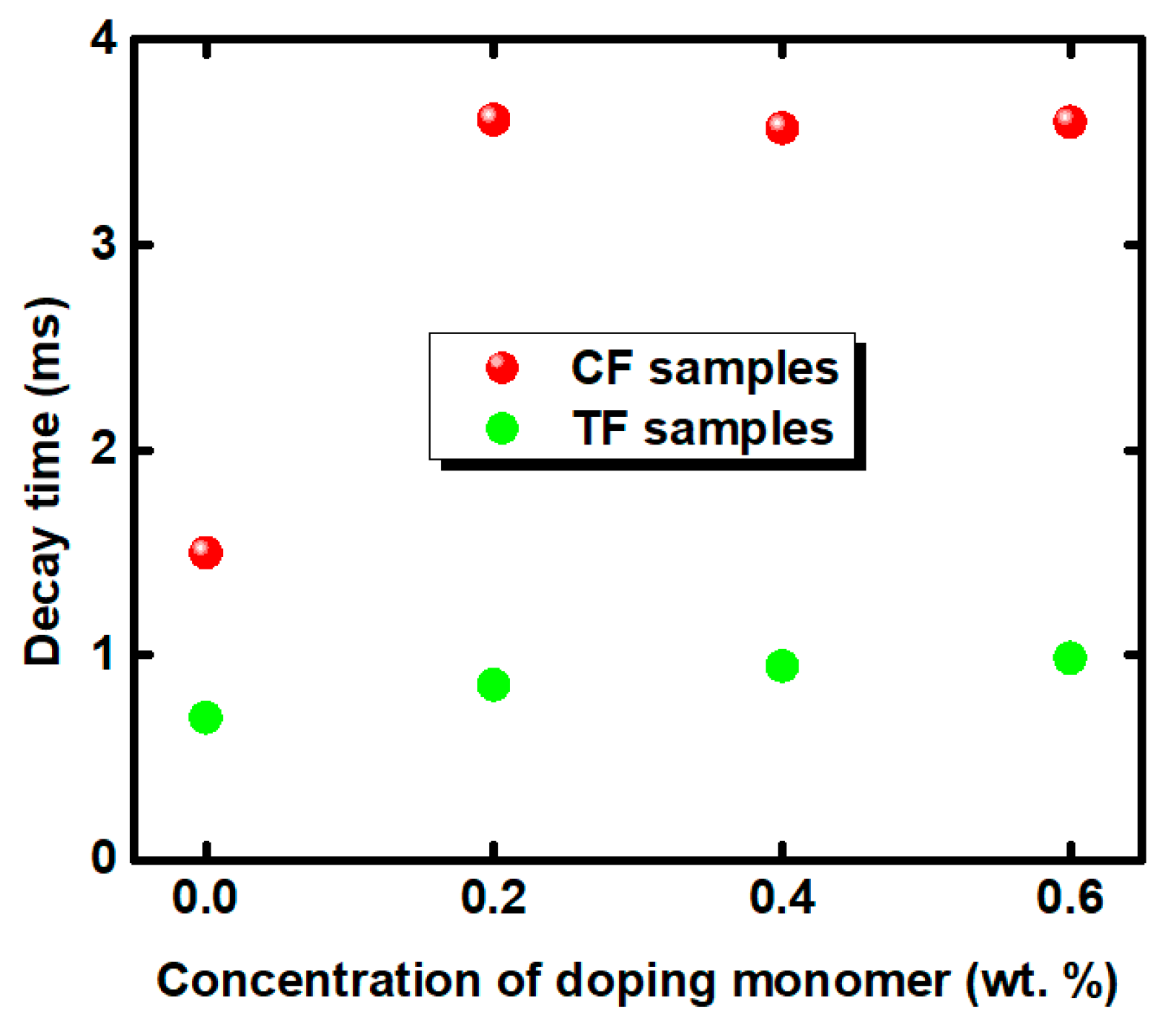
3.4. Response Time
4. Conclusions
Author Contributions
Funding
Conflicts of Interest
References
- Kikuchi, H.; Yokota, M.; Hisakado, Y.; Yang, H.; Kajiyama, T. Polymer-stabilized liquid crystal blue phases. Nat. Mater. 2002, 1, 64–68. [Google Scholar] [CrossRef] [PubMed]
- Hisakado, Y.; Kikuchi, H.; Nagamura, T.; Kajiyama, T. Large electro-optic Kerr effect in polymer-stabilized liquid-crystalline blue phases. Adv. Mater. 2005, 17, 96–98. [Google Scholar] [CrossRef]
- Higashiguchi, K.; Yasui, K.; Kikuchi, H. Direct observation of polymer-stabilized blue phase I structure with confocal laser scanning microscope. J. Am. Chem. Soc. 2008, 130, 6326–6327. [Google Scholar] [CrossRef] [PubMed]
- Castles, F.; Day, F.V.; Morris, S.M.; Ko, D.H.; Gardiner, D.J.; Qasim, M.M.; Nosheen, S.; Hands, P.J.W.; Choi, S.S.; Friend, R.H.; et al. Blue-phase templated fabrication of three-dimensional nanostructures for photonic applications. Nat. Mater. 2012, 11, 599–603. [Google Scholar] [CrossRef] [PubMed]
- Coles, H.J.; Pivnenko, M.N. Liquid crystal ‘blue phases’ with a wide temperature range. Nature 2005, 436, 997–1000. [Google Scholar] [CrossRef] [PubMed]
- Yan, J.; Rao, L.; Jiao, M.; Li, Y.; Cheng, H.C.; Wu, S.T. Polymer-stabilized optically isotropic liquid crystals for next-generation display and photonics applications. J. Mater. Chem. 2011, 21, 7870–7877. [Google Scholar] [CrossRef]
- Gerber, P.R. Electro-optical effects of a small-pitch blue-phase system. Mol. Cryst. Liq. Cryst. 1985, 116, 197–206. [Google Scholar] [CrossRef]
- Martínez-González, J.A.; Li, X.; Sadati, M.; Zhou, Y.; Zhang, R.; Nealey, P.F.; de Pablo, J.J. Directed self-assembly of liquid crystalline blue-phases into ideal single-crystals. Nat. Commun. 2017, 8, 15854. [Google Scholar] [CrossRef]
- Gharbi, M.A.; Manet, S.; Lhermitte, J.; Brown, S.; Milette, J.; Toader, V.; Reven, L. Reversible nanoparticle cubic lattices in blue phase liquid crystals. ACS Nano. 2016, 10, 3410–3415. [Google Scholar] [CrossRef]
- Henrich, O.; Stratford, K.; Cates, M.E.; Marenduzzo, D. Structure of blue phase III of cholesteric liquid crystals. Phys. Rev. Lett. 2011, 106, 107801. [Google Scholar] [CrossRef]
- Choi, H.; Higuchi, H.; Kikuchi, H. Fast electro-optic switching in liquid crystal blue phase II. Appl. Phys. Lett. 2011, 98, 131905. [Google Scholar] [CrossRef]
- Kim, S.; Kim, K.; Jo, S.Y.; Choi, S.W. Uniform alignment of liquid crystalline cubic blue phase II via rubbing treatment. Mol. Cryst. Liq Cryst. 2015, 611, 186–191. [Google Scholar] [CrossRef]
- Zhou, K.; Bisoyi, H.K.; Jin, J.Q.; Yuan, C.L.; Liu, Z.; Shen, D.; Lu, Y.Q.; Zheng, Z.; Zhang, W.; Li, Q. Light-Driven Reversible Transformation between Self-Organized Simple Cubic Lattice and Helical Superstructure Enabled by a Molecular Switch Functionalized Nanocage. Adv. Mater. 2018, 30, 1800237. [Google Scholar] [CrossRef] [PubMed]
- Wang, M.; Zou, C.; Li, C.; Sun, J.; Wang, L.; Hu, W.; Zhang, C.H.; Zhang, L.Y.; He, W.L.; Yang, H. Bias-Polarity Dependent Bidirectional Modulation of Photonic Bandgap in a Nanoengineered 3D Blue Phase Polymer Scaffold for Tunable Laser Application. Adv. Opt. Mater. 2018, 6, 1800409. [Google Scholar] [CrossRef]
- Yuan, Y.; Li, Y.; Chen, C.P.; Liu, S.; Rong, N.; Li, W.; Li, X.; Zhou, P.; Lu, J.; Liu, R. Polymer-stabilized blue-phase liquid crystal grating cured with interfered visible light. Opt. Express 2015, 23, 20007–20013. [Google Scholar] [CrossRef]
- Lin, J.D.; Huang, S.Y.; Wang, H.S.; Lin, S.H.; Mo, T.S.; Horng, C.T.; Yeh, H.C.; Chen, L.J.; Lin, H.L.; Lee, C.R. Spatially tunable photonic bandgap of wide spectral range and lasing emission based on a blue phase wedge cell. Opt. Express 2014, 22, 29479–29492. [Google Scholar] [CrossRef] [PubMed]
- Chen, K.M.; Gauza, S.; Xianyu, H.; Wu, S.T. Submillisecond gray-level response time of a polymer-stabilized blue-phase liquid crystal. J. Display. Technol. 2010, 6, 49–51. [Google Scholar] [CrossRef]
- Huang, Y.; Chen, H.; Tan, G.; Tobata, H.; Yamamoto, S.-I.; Okabe, E.; Lan, Y.F.; Tsai, C.Y.; Wu, S.T. Optimized blue-phase liquid crystal for field-sequential-color displays. Opt. Mater. Express 2017, 7, 641–650. [Google Scholar] [CrossRef]
- Chen, Y.; Xu, D.; Wu, S.T.; Yamamoto, S.I.; Haseba, Y. A low voltage and submillisecond-response polymer-stabilized blue phase liquid crystal. Appl. Phys. Lett. 2013, 102, 141116. [Google Scholar] [CrossRef] [Green Version]
- Ge, Z.; Rao, L.; Gauza, S.; Wu, S.T. Modeling of blue phase liquid crystal displays. J. Display. Technol. 2009, 5, 250–256. [Google Scholar] [CrossRef]
- Yan, J.; Guo, Z.; Xing, Y.; Li, Q. Investigation of fringing electric field effect on high-resolution blue phase liquid crystal spatial light modulator. Appl. Opt. 2015, 54, 7169–7174. [Google Scholar] [CrossRef] [PubMed]
- Tan, J.; Song, Y.; Zhu, J.L.; Ni, S.B.; Wang, Y.J.; Sun, X.Y.; Lu, J.G.; Yang, B.R.; Shieh, H.P.D. Blue phase LC/polymer Fresnel lens fabricated by holographics. J. Display. Technol. 2013, 10, 157–161. [Google Scholar] [CrossRef]
- Liu, Y.; Lan, Y.F.; Zhang, H.; Zhu, R.; Xu, D.; Tsai, C.Y.; Lu, J.K.; Sugiura, N.; Lin, Y.-C.; Wu, S.T. Optical rotatory power of polymer-stabilized blue phase liquid crystals. Appl. Phys. Lett. 2013, 102, 131102. [Google Scholar] [CrossRef] [Green Version]
- Chen, K.M.; Gauza, S.; Xianyu, H.; Wu, S.T. Hysteresis effects in blue-phase liquid crystals. J. Display. Technol. 2010, 6, 318–322. [Google Scholar] [CrossRef]
- Rao, L.; Yan, J.; Wu, S.T.; Lai, Y.C.; Chiu, Y.H.; Chen, H.Y.; Liang, C.C.; Wu, C.M.; HSieh, P.J.; Liu, S.J.; et al. Critical field for a hysteresis-free BPLC device. J. Display. Technol. 2011, 7, 627–629. [Google Scholar]
- Lan, Y.F.; Tsai, C.Y.; Lu, J.K.; Sugiura, N. Mechanism of hysteresis in polymer-network stabilized blue phase liquid crystal. Polymer (Guildf.) 2013, 54, 1876–1879. [Google Scholar] [CrossRef]
- Rao, L.; Ge, Z.; Wu, S.T.; Lee, S.H. Low voltage blue-phase liquid crystal displays. Appl. Phys. Lett. 2009, 95, 231101. [Google Scholar] [CrossRef] [Green Version]
- Cheng, H.C.; Yan, J.; Ishinabe, T.; Wu, S.T. Vertical field switching for blue-phase liquid crystal devices. Appl. Phys. Lett. 2011, 98, 261102. [Google Scholar] [CrossRef] [Green Version]
- Rao, L.; Yan, J.; Wu, S.T.; Yamamoto, S.; Haseba, Y. A large Kerr constant polymer-stabilized blue phase liquid crystal. Appl. Phys. Lett. 2011, 98, 081109. [Google Scholar] [CrossRef] [Green Version]
- Hsieh, P.J.; Chen, H.-M.P. Hysteresis-free polymer-stabilised blue phase liquid crystals comprising low surface tension monomers. Liq. Cryst. 2015, 42, 216–221. [Google Scholar] [CrossRef]
- Yan, J.; Cheng, H.C.; Gauza, S.; Li, Y.; Jiao, M.; Rao, L.; Wu, S.T. Extended Kerr effect of polymer-stabilized blue-phase liquid crystals. Appl. Phys. Lett. 2010, 96, 071105. [Google Scholar] [CrossRef] [Green Version]


| Sample | BPLC (wt %) | RM257 (wt %) | C12A (wt %) | TMPTA (wt %) | ETB (wt %) | RG184 (wt %) |
|---|---|---|---|---|---|---|
| CF0 | 92.0 | 4.2 | 3.5 | \ | 0 | 0.3 |
| CF2 | 3.3 | \ | 0.2 | |||
| CF4 | 3.1 | \ | 0.4 | |||
| CF6 | 2.9 | \ | 0.6 | |||
| TF0 | 92.0 | 4.2 | \ | 3.5 | 0 | 0.3 |
| TF2 | \ | 3.3 | 0.2 | |||
| TF4 | \ | 3.1 | 0.4 | |||
| TF6 | \ | 2.9 | 0.6 |
© 2019 by the authors. Licensee MDPI, Basel, Switzerland. This article is an open access article distributed under the terms and conditions of the Creative Commons Attribution (CC BY) license (http://creativecommons.org/licenses/by/4.0/).
Share and Cite
Gao, L.; Wang, K.-M.; Zhao, R.; Ma, H.-M.; Sun, Y.-B. Effect of a Dual Functional Polymer on the Electro-Optical Properties of Blue Phase Liquid Crystals. Polymers 2019, 11, 1128. https://doi.org/10.3390/polym11071128
Gao L, Wang K-M, Zhao R, Ma H-M, Sun Y-B. Effect of a Dual Functional Polymer on the Electro-Optical Properties of Blue Phase Liquid Crystals. Polymers. 2019; 11(7):1128. https://doi.org/10.3390/polym11071128
Chicago/Turabian StyleGao, Liang, Ke-Meng Wang, Rui Zhao, Hong-Mei Ma, and Yu-Bao Sun. 2019. "Effect of a Dual Functional Polymer on the Electro-Optical Properties of Blue Phase Liquid Crystals" Polymers 11, no. 7: 1128. https://doi.org/10.3390/polym11071128