The Influence of the Use of Polymer Lining within the Roller Press Gravity Feeder on Briquette Quality


Abstract
:
1. Introduction
2. Materials and Methods
- materials of inorganic origin:
- hydrated lime,
- artificial fertiliser for lawns,
- material of organic origin/fuels:
- charcoal,
- heavy industry waste:
- electric arc furnace dust (EAFD) mixtures.
3. Results
4. Discussion
5. Conclusions
Funding
Acknowledgments
Conflicts of Interest
References
- Zhang, G.; Sun, Y.; Xu, Y. Review of briquette binders and briquetting mechanism. Renew. Sustain. Energy Rev. 2018, 82, 477–487. [Google Scholar] [CrossRef]
- Mroziński, A.; Flizikowski, J.; Tomporowski, A.; Kruszelnicka, W.; Piasecka, I.; Kasner, R. Research of Wood Biomass Briquetting Process. Res. Gate 2018, 2. [Google Scholar] [CrossRef]
- Bembenek, M.; Wdaniec, P.; Baran, E. Production of a granulated mineral fertilizer from waste gypsum in a flat-matrix granulator. Przem. Chem. 2020, 99, 236–238. (In Polish) [Google Scholar] [CrossRef]
- Talaśka, K.; Malujda, I.; Wilczyński, D. Agglomeration of Natural Fibrous Materials in Perpetual Screw Technique—A Challenge for Designer. Procedia Eng. 2016, 136, 63–69. [Google Scholar] [CrossRef] [Green Version]
- Kruszelnicka, W. A New Model for Environmental Assessment of the Comminution Process in the Chain of Biomass Energy Processing. Energies 2020, 13, 330. [Google Scholar] [CrossRef] [Green Version]
- Pietsch, W. An interdisciplinary approach to size enlargement by agglomeration. Powder Technol. 2003, 130, 8–13. [Google Scholar] [CrossRef]
- Magdziarz, A.; Kuźnia, M.; Bembenek, M.; Gara, P.; Hryniewicz, M. Briquetting of EAF dust for its utilisation in metallurgical processes. Chem. Process. Eng. 2015, 36, 263–271. [Google Scholar] [CrossRef] [Green Version]
- Macko, M.; Mroziński, A.; Prentki, A. Simulations CAE of wood pellet machine. MATEC Web Conf. 2019, 254, 02028. [Google Scholar] [CrossRef]
- Obidziński, S. Pelletization process of postproduction plant waste. Int. Agrophys. 2012, 3, 279–284. [Google Scholar] [CrossRef]
- Baiul, K.V. Synthesis of Roller Press Rational Design for Composite Solid Fuel Production. Probl. Energeticii Reg. 2019, 2, 103–116. [Google Scholar] [CrossRef]
- Bembenek, M. Research and prospects for new areas of using roller presses. Przem. Chem. 2017, 9, 1845–1847. (In Polish) [Google Scholar] [CrossRef]
- Hryniewicz, M.; Bembenek, M.; Janewicz, A.; Kosturkiewicz, B. Agglomeration of fine-grained materials in roll presses with asymmetrical compaction unit. Przem. Chem. 2015, 94, 2223–2226. (In Polish) [Google Scholar] [CrossRef]
- Baiul, K.; Solodka, N.; Khudyakov, A.; Vashchenko, S.V. Selection of rational surface configuration for roller press tires. Powder Metall. Met. Ceram. 2020, 9–21. [Google Scholar] [CrossRef]
- Kosturkiewicz, B.; Janewicz, A.; Hryniewicz, M. Selection method for the roll press feeder. J. Mach. Constr. Maint. 2017, 3, 45–51. [Google Scholar]
- Karwat, B.; Rubacha, P.; Stańczyk, E. Simulational and experimental determination of the exploitation parameters of a screw conveyor. Eksploat. Niezawodn. 2020, 22, 741–747. [Google Scholar] [CrossRef]
- Kothalkar, C.; Modak, J.P.; Tatwawadi, V.H.; Dey, A.C. Variable Dispensing Capacity Screw Feeder Based Powder Dispenser: Improving the Design by Studying the Effect of the Hopper Side Wall Slope (φs) on Performance of the Dispenser. IJERT 2013, 2, 2823–2832. [Google Scholar]
- Dutta, A.B.; Kolhatkar, M. Study of Types of Failures in Silos. GJRA 2013, 2, 41–43. [Google Scholar]
- Bradley, M.S.A.; Berry, R.J.; Farnish, R.J. Methods for Design of Hoppers. Silos, Bins and Bunkers for Reliable Gravity Flow, for Pharmaceutical, Food, Mineral and Other Applications. In Wolfson Centre for Bulk Solids Handling Technology; University of Greenwich: Chatham, UK, 2015. [Google Scholar]
- Schulze, D. Powders and Bulk Solids: Behavior, Characterization, Storage and Flow; Springer: Berlin/Heidelberg, Germany, 2007. [Google Scholar] [CrossRef]
- Tomporowski, A.; Flizikowski, J.; Kruszelnicka, W. A new concept of roller-plate mill. Przem. Chem. 2017, 96, 1750–1755. (In Polish) [Google Scholar] [CrossRef]
- Kumar, V.; Arora, R.; Goyal, D.; Pal, D.; Sehgal, S. Investigations of powder flow patterns in hopper model through discrete element method. Met. Powder Rep. 2020, 75, 40–47. [Google Scholar] [CrossRef]
- Gallego, E.; Ruiz, A.; Aguado, P.J. Simulation of silo filling and discharge using ANSYS and comparison with experimental data. Comput. Electron. Agric. 2015, 118, 281–289. [Google Scholar] [CrossRef]
- Sielamowicz, I.; Belevicius, R. Experimental and Computational Analysis of Granular Material Flow in Model Silos. IPPT Rep. Fundam. Technol. Res. 2013, 1, 1–317. [Google Scholar]
- Tangri, H.; Guo, Y.; Curtis, J.S. Hopper discharge of elongated particles of varying aspect ratio: Experiments and DEM simulations. Chem. Eng. Sci. X 2019, 4. [Google Scholar] [CrossRef]
- Grudzień, K.; Chaniecki, Z.; Romanowski, A.; Niedostatkiewicz, M.; Sankowski, D. ECT Image Analysis Methods for Shear Zone Measurements during Silo Discharging Process. Chin. J. Chem. Eng. 2012, 20, 337–345. [Google Scholar] [CrossRef]
- Albaraki, S.; Antony, S.J. How does internal angle of hoppers affect granular flow? Experimental studies using digital particle image velocimetry. Powder Technol. 2014, 268, 253–260. [Google Scholar] [CrossRef]
- Liao, Z.; Xu, J.; Sun, C.; Yang, Y.; Pei, Y.; Kou, M.; Hu, Z.; Meng, L.; Wen, L. Influence of particle packed pattern on the transient granular flow in a wedge-shaped hopper. Adv. Powder Technol. 2020, 31, 670–677. [Google Scholar] [CrossRef]
- Lobato, J.C.; Mascarenhas, F.P.; Mesquita, A.L.A. Conical hopper design for mass flow—Case of red mud. Holos 2016, 2, 120–131. [Google Scholar] [CrossRef] [Green Version]
- López-Rodríguez, D.; Gella, D.; To, K.; Maza, D.; Garcimartín, A.; Zuriguel, I. Effect of hopper angle on granular clogging. Phys. Rev. 2019, 99. [Google Scholar] [CrossRef] [PubMed] [Green Version]
- Staron, L.; Lagrée, P.-L.; Popinet, S. The granular silo as a continuum plastic flow: The hour-glass vs the clepsydra. Phys. Fluids 2012, 24, 1–8. [Google Scholar] [CrossRef] [Green Version]
- Wang, X.; Yang, Z.; Li, B. The Friction Stress Distribution of Loose Materials to Silo Walls in Deep Pyramidal Silos. KONA 2018, 35, 273–282. [Google Scholar] [CrossRef] [Green Version]
- Serrano, D.A.; Medina, A.; Ruiz Chavarria, G.; Pliego, M.; Klapp, J. Mass flow rate of granular material flowing from tilted bins. Powder Technol. 2015, 286, 438–443. [Google Scholar] [CrossRef]
- Huang, X.; Zheng, Q.; Yu, A.; Yan, W. Optimised curved hoppers with maximum mass discharge rate—An experimental study. Powder Technol. 2020, 377, 350–360. [Google Scholar] [CrossRef]
- Huang, X.; Zheng, Q.; Yu, A.; Yan, W. Shape optimization of conical hoppers to increase mass discharging rate. Powder Technol. 2020, 361, 179–189. [Google Scholar] [CrossRef]
- Larsson, S. Particle Methods for Modelling Granular Material Flow. Ph.D. Thesis, Luleä University of Technology, Luleä, Sweden, 2019. [Google Scholar]
- Zhang, T.F.; Gan, J.Q.; Pinson, D.; Zhou, Z.Y. Size-induced segregation of granular materials during filling a conical hopper. Powder Technol. 2018, 340, 331–343. [Google Scholar] [CrossRef]
- Mellmann, J.; Hoffman, T.; Fürll, C. Mass flow during unloading of agricultural bulk materials from silos depending on particle form, flow properties and geometry of the discharge opening. Powder Technol. 2014, 253, 46–52. [Google Scholar] [CrossRef]
- Fank, M.Z.; Nascimento, J.W.B.; Cardoso, D.L.; Meira, A.S.; Willrich, F.L. Vertical pressures and compressive friction force in a large silo. Eng. Agric. 2018, 38, 498–503. [Google Scholar] [CrossRef]
- Calderon, C.A.; Villagran Olivares, M.C.; Unac, R.O.; Vidales, A.M. Correlations between flow rate parameters and the shape of the grains in a silo discharge. Powder Technol. 2017, 320, 43–50. [Google Scholar] [CrossRef]
- Hammadeh, H.; Askifi, F.; Ubysz, A.; Maj, M.; Zeno, A. Effect of using insert on the flow pressure in cylindrical silo. Studia Geotech. Mech. 2019, 41, 1–7. [Google Scholar] [CrossRef] [Green Version]
- To, K.; Yen, Y.; Mo, Y.; Huang, J. Granular flow from silos with rotating orifice. Phys. Rev. 2019, 100. [Google Scholar] [CrossRef] [Green Version]
- Sun, D.; Lu, H.; Cao, J.; Wu, Y.; Guo, X.; Gong, X. Flow mechanisms and solid flow rate prediction of powders discharged from hoppers with an insert. Powder Technol. 2020, 367, 277–284. [Google Scholar] [CrossRef]
- Shelley, S. Ensure proper material flow with these vibrating hoppers. Chem. Eng. 2015, 122, 33. [Google Scholar]
- Zhang, C.; Qiu, C.; Pu, C.; Fan, X.; Cao, P. The mechanism of vibrations-aided gravitational flow with overhanging style in hopper. Powder Technol. 2018, 327, 291–302. [Google Scholar] [CrossRef]
- Pneumatic Impactors Series PKL from the Industry Leader. Available online: https://www.nettervibration.com/product-line/pneumatic-impactors-series-pkl/?lang=en (accessed on 25 July 2020).
- Aussillous, P.; Zhou, Y.; Ruyer, P.; Lagrée, P.-L. Discharge flow of granular media from silos with a lateral orifice and injection of air. EPJ Web Conf. 2017, 140, 1–4. [Google Scholar] [CrossRef]
- Lu, H.; Cao, J.; Guo, X.; Gong, X.; Fu, L. Design optimization of an aerated hopper for discharge of cohesive pulverized coal. Powder Technol. 2019, 357, 186–192. [Google Scholar] [CrossRef]
- Wyleciał, T.; Urbaniak, D.; Zajemska, M.; Boryca, J. Research of bulk material granularity influence on the fluidized pneumatic sluice efficiency. Inż. Ap. Chem. 2017, 56, 222–223. (In Polish) [Google Scholar]
- Poliacetal (pom)–TWORZYWA SZTUCZNE–Tworzywa Sztuczne–Plastem. Available online: http://www.plastem.pl/oferta/tworzywa-sztuczne/poliacetal-pom/ (accessed on 25 July 2020).
- Polietylen PE 1000, 500, 300—Tecafine, Boraflon, Tivar. Available online: https://enimat.pl/polietylen-pe/ (accessed on 25 July 2020).
- Nawóz do Trawników Super Wieloskładnikowy—Agrecol. Available online: https://agrecol.pl/produkt/nawoz-do-trawnikow-super-wieloskladnikowy/ (accessed on 25 July 2020).


| Paramert | POM C | UHMW-PE |
|---|---|---|
| Yield Point, MPa | 67 | 17 |
| Elongation at Yield point, % | 9 | 20 |
| Stress at Break, MPa | 67 | 50 |
| Impact strength with Notch (Charpy), kJ/m2 | 165 | 170 |
| Melting Point, °C | 166 | 130 |
| Long-lasting Maximum Usable Temperature °C | 140 | 80 |
| Density, g/cm3 | 1.41 | 0.93 |
| Water Absorption, % | 0.1 | 0.01 |
| Parameter | POM C, μm | UHMW-PE, μm |
|---|---|---|
| Rz—Greatest Height of the Profile | 13.88 | 4.91 |
| Rt—Total Height of the Profile | 18.82 | 8.97 |
| Ra—Arithmetic Mean of the Profile Ordinates | 2.56 | 0.73 |
| Sm—Average Width of Grooves of the Profile Elements | 364.0 | 225.1 |
| Parameter | Without Lining | POM C | UHMW-PE |
|---|---|---|---|
| Material 1—Calcium Hydroxide | |||
| Drop Strength after 1 Day, % | 43.8 | 82.5 | 59.1 |
| Drop Strength after 30 Days, % | 60.8 | 80.6 | 64.0 |
| Compressive Strength after 1 Day, n | 105.7 | 153.6 | 99.5 |
| Compressive Strength after 30 Days, n | 136.5 | 271.9 | 218.8 |
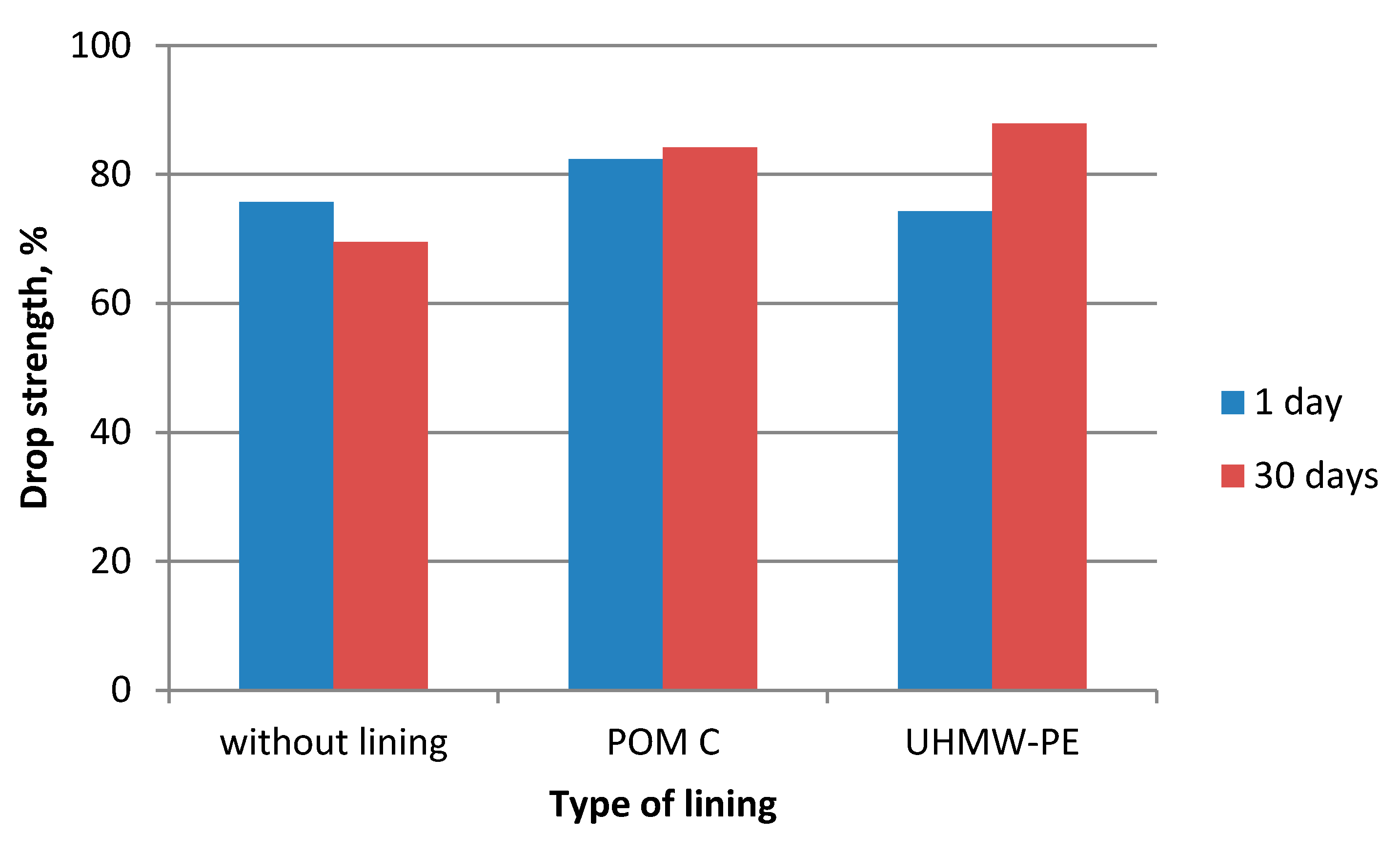
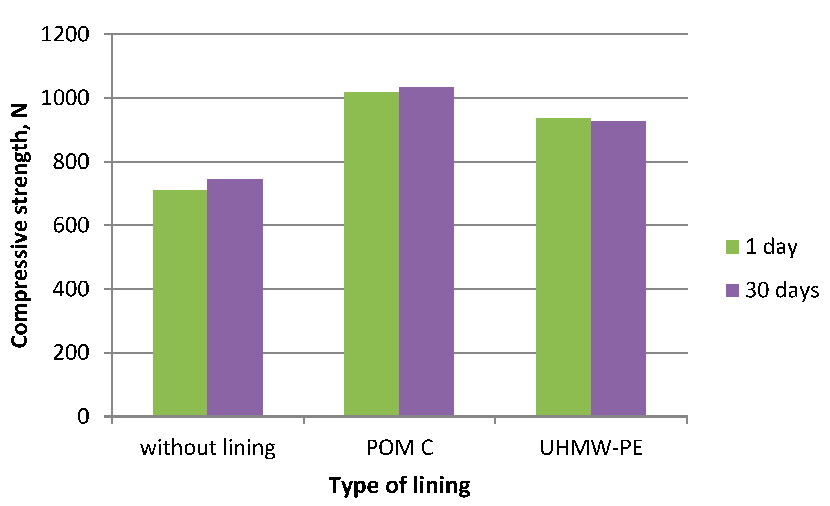
| Material 2—Fertiliser | |||
| Drop Strength after 1 Day, % | 75.7 | 82.4 | 74.3 |
| Drop Strength after 30 Days, % | 69.5 | 84.2 | 87.9 |
| Compressive Strength after 1 Day, n | 709.6 | 1018.4 | 936.6 |
| Compressive Strength after 30 Days, n | 746.6 | 1032.8 | 927.0 |
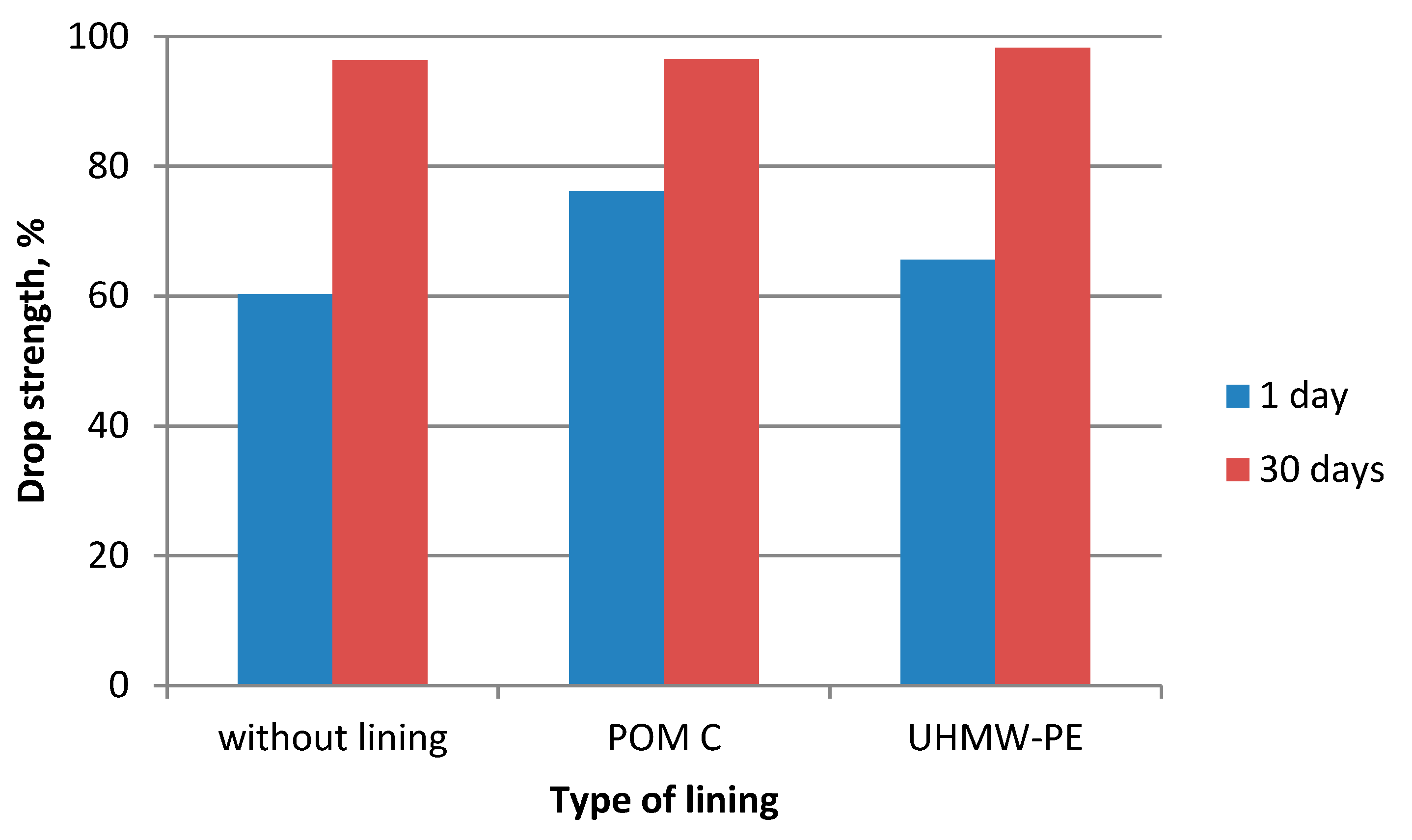
| Material 3—Charcoal Fines Mixed with 4% of Starch | |||
| Drop Strength after 1 Day, % | 60.3 | 76.2 | 65.6 |
| Drop Strength after 30 Day, % | 96.4 | 96.5 | 98.3 |
| Compressive Strength after 1 Days, n | -- 1 | -- 1 | -- 1 |
| Compressive Strength after 30 Days, n | 279.8 | 290.9 | 302.3 |
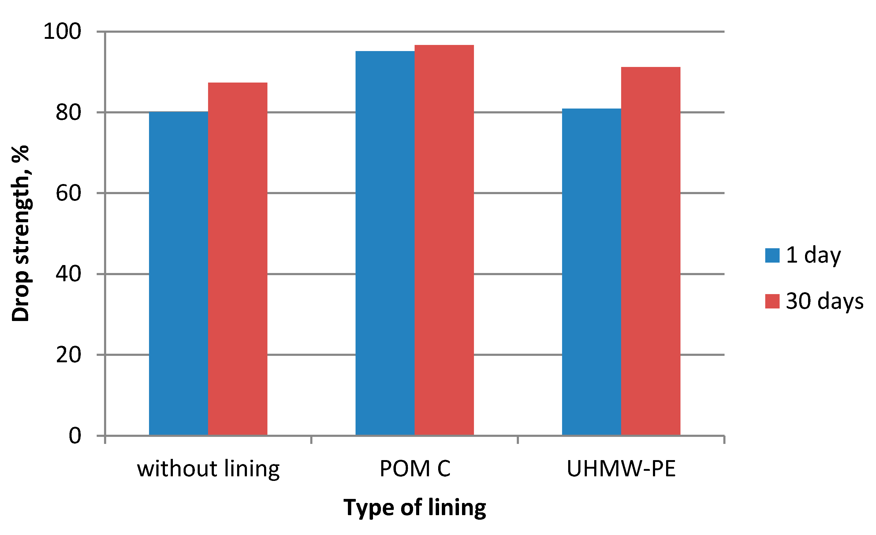
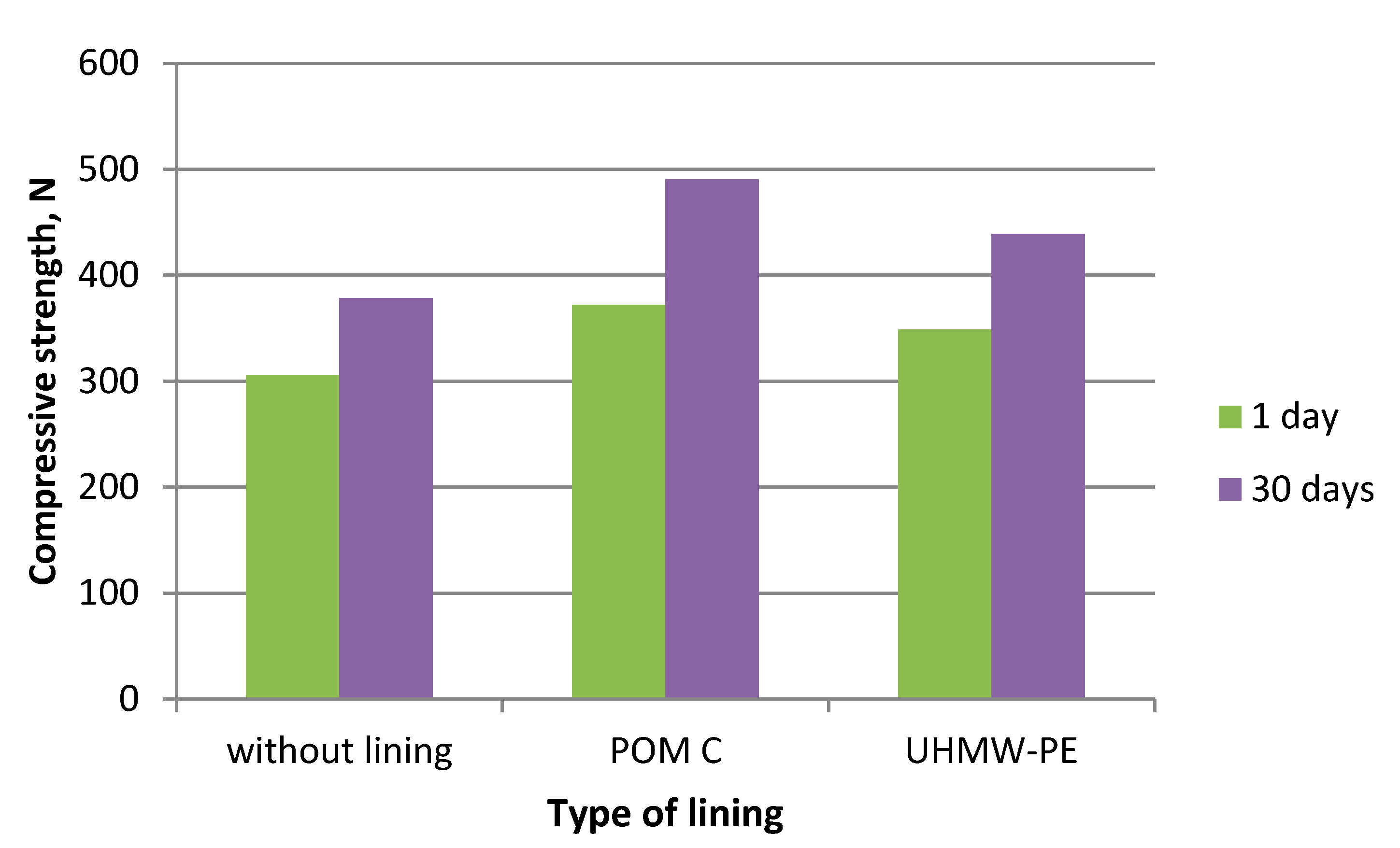
| Material 6—EAFD Mixture | |||
| Drop Strength after 1 Day, % | 80.1 | 95.1 | 80.9 |
| Drop Strength after 30 Days, % | 87.3 | 96.6 | 91.2 |
| Compressive Strength after 1 Day, n | 306 | 398.8 | 383.1 |
| Compressive Strength after 30 Days, n | 378.3 | 490.3 | 438.8 |
| Parameter | POM C | UHMW-PE | ||
|---|---|---|---|---|
| 1 day | 30 Days | 1 Day | 30 Days | |
| Material 1—Calcium Hydroxide | ||||
| Drop Strength, % | 88.4 | 32.6 | 34.9 | 5.3 |
| Compressive Strength, % | 45.3 | 99.2 | −5.9 | 60.3 |
| Material 2—Fertiliser | ||||
| Drop Strength, % | 8.9 | 21.2 | −1.8 | 26.5 |
| Compressive Strength, % | 43.5 | 38.3 | 32.0 | 24.2 |
| Material 3—Charcoal Fines Mixed with 4% of Starch | ||||
| Drop Strength, % | 26.4 | 0.1 | 8.8 | 2.0 |
| Compressive Strength, % | -- 1 | 4.0 | -- 1 | 8.0 |
| Material 6—EAFD Mixture | ||||
| Drop Strength, % | 18.7 | 10.7 | 1.0 | 4.5 |
| Compressive Strength, % | 21.6 | 29.6 | 13.9 | 16.0 |
Publisher’s Note: MDPI stays neutral with regard to jurisdictional claims in published maps and institutional affiliations. |
© 2020 by the author. Licensee MDPI, Basel, Switzerland. This article is an open access article distributed under the terms and conditions of the Creative Commons Attribution (CC BY) license (http://creativecommons.org/licenses/by/4.0/).
Share and Cite
Bembenek, M. The Influence of the Use of Polymer Lining within the Roller Press Gravity Feeder on Briquette Quality. Polymers 2020, 12, 2489. https://doi.org/10.3390/polym12112489
Bembenek M. The Influence of the Use of Polymer Lining within the Roller Press Gravity Feeder on Briquette Quality. Polymers. 2020; 12(11):2489. https://doi.org/10.3390/polym12112489
Chicago/Turabian StyleBembenek, Michał. 2020. "The Influence of the Use of Polymer Lining within the Roller Press Gravity Feeder on Briquette Quality" Polymers 12, no. 11: 2489. https://doi.org/10.3390/polym12112489
APA StyleBembenek, M. (2020). The Influence of the Use of Polymer Lining within the Roller Press Gravity Feeder on Briquette Quality. Polymers, 12(11), 2489. https://doi.org/10.3390/polym12112489