Morphology, Thermal and Mechanical Properties of Co-Continuous Porous Structure of PLA/PVA Blends by Phase Separation


Abstract
:1. Introduction
2. Materials and Methods
2.1. Materials
2.2. Sample Preparation
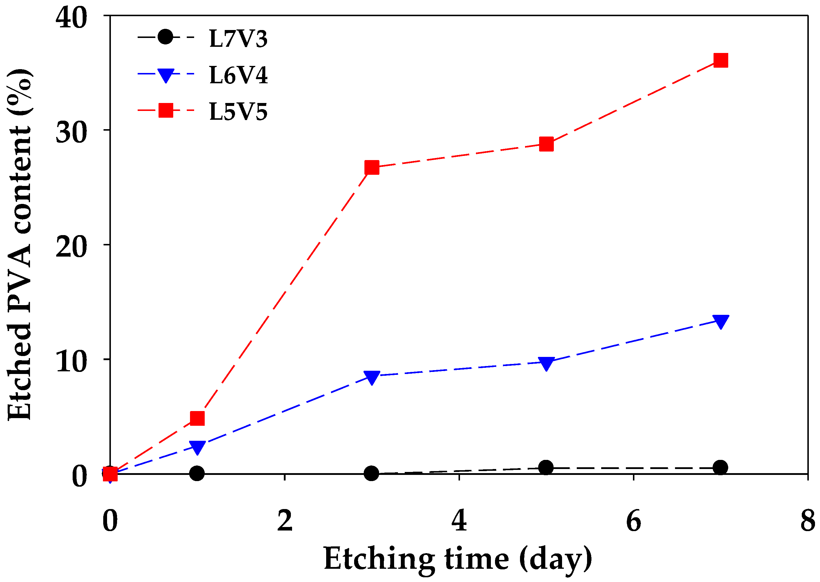
2.3. Phase Separation
2.4. Characterization
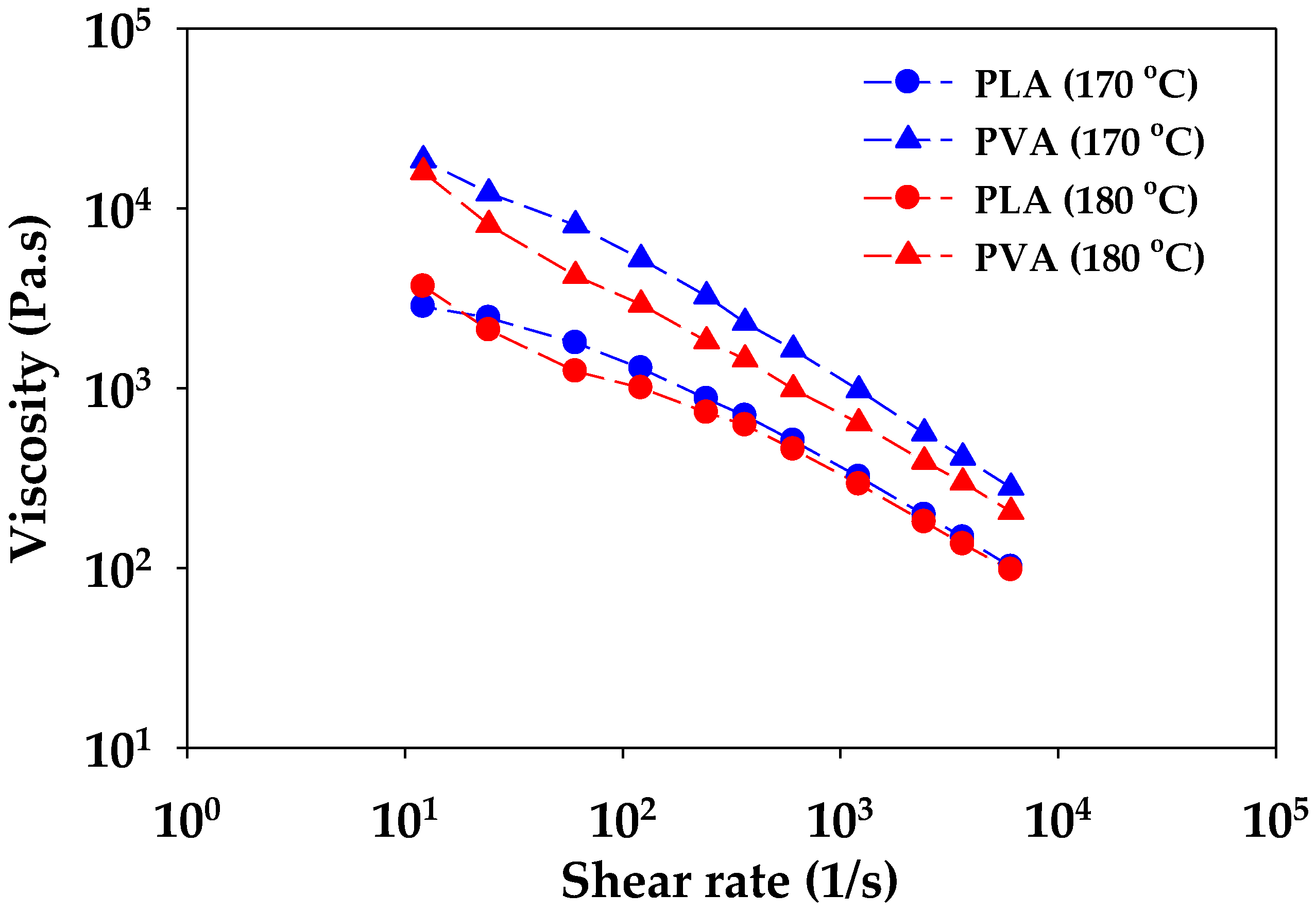
2.4.1. Rheology
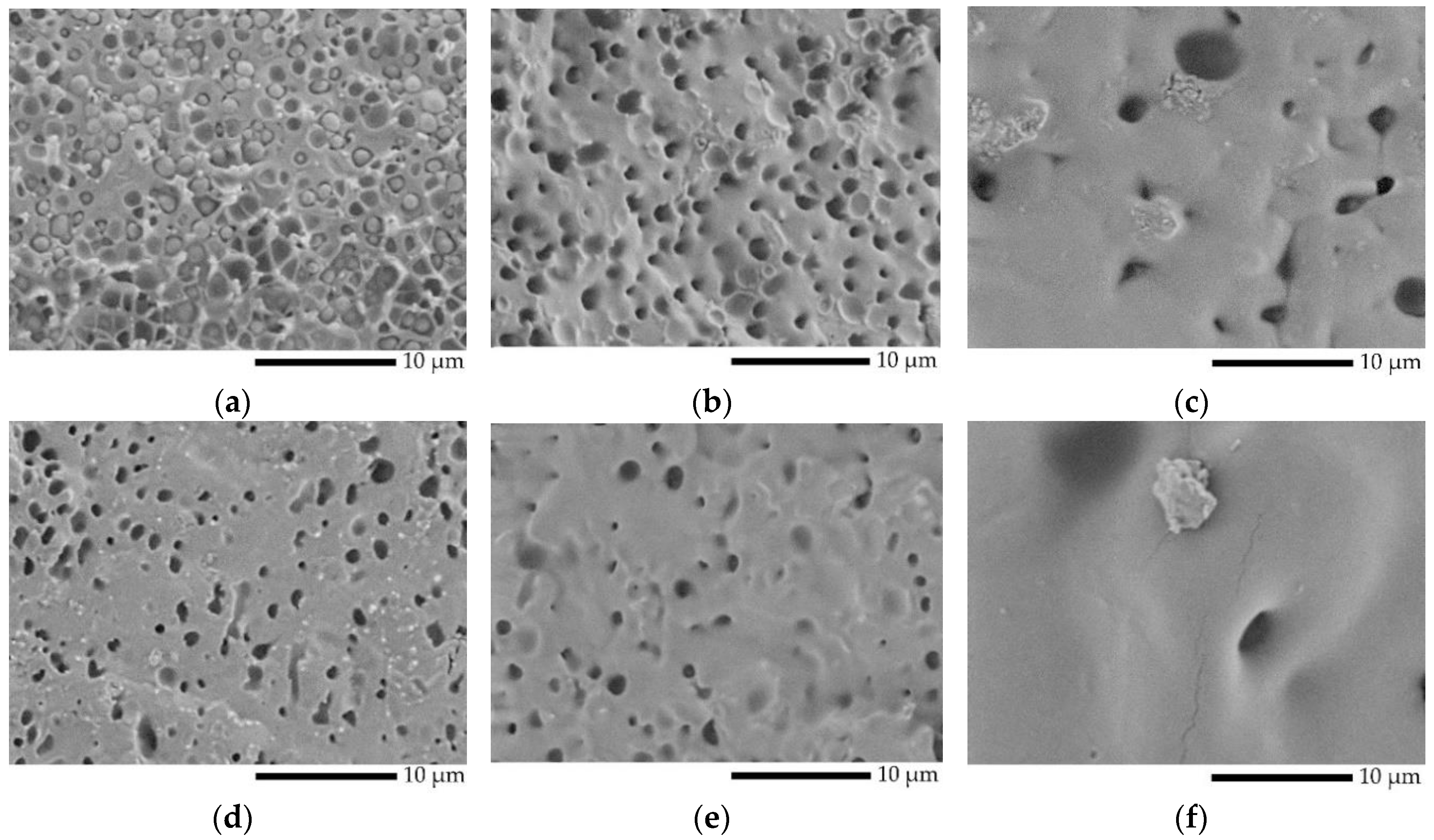
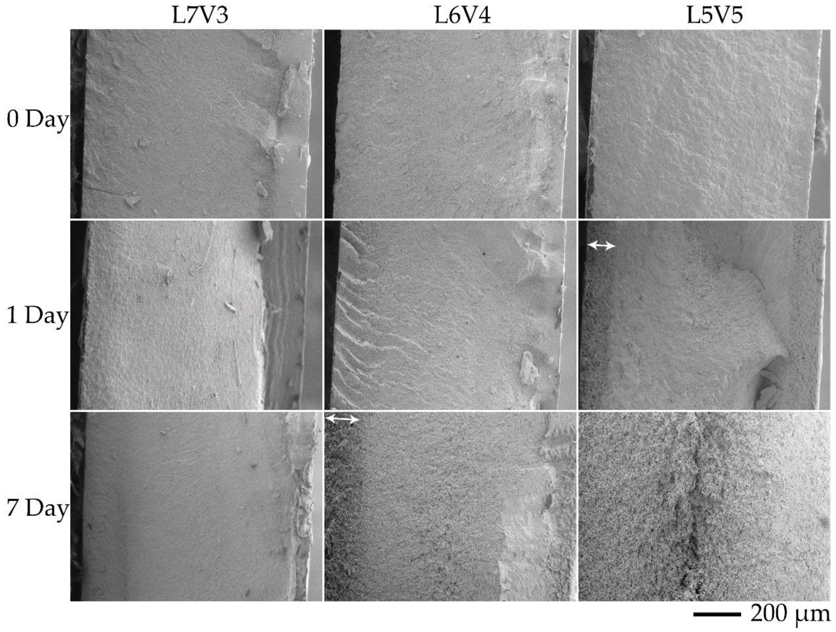
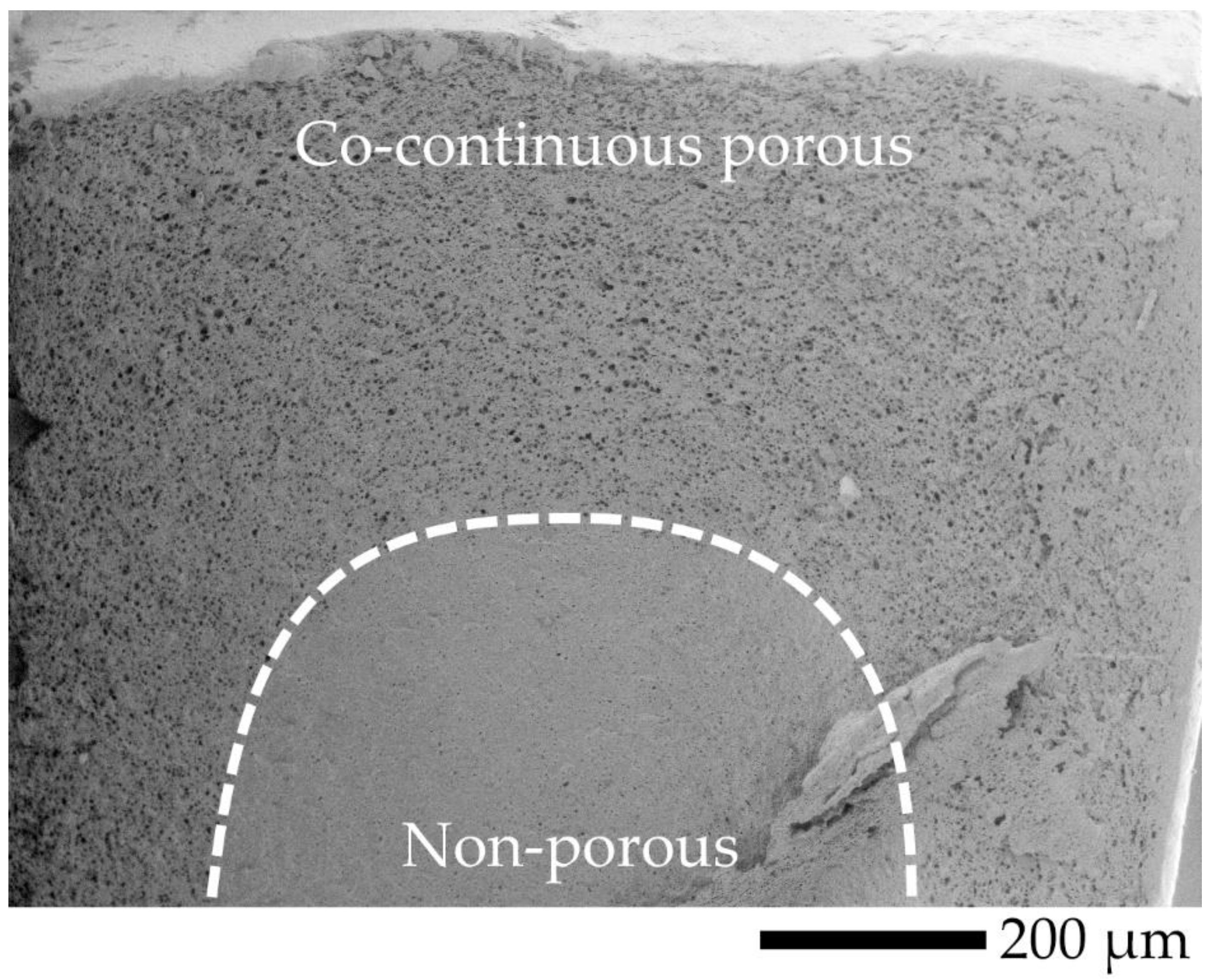
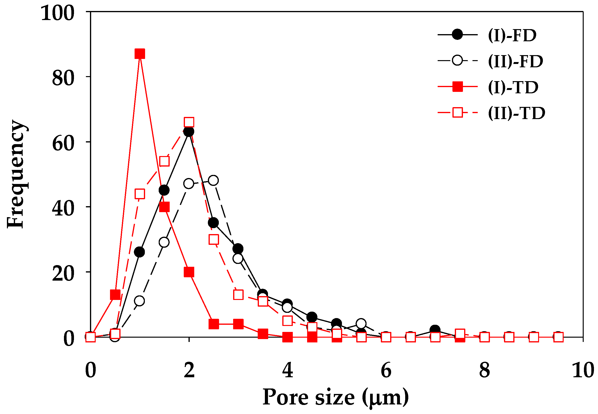
2.4.2. Morphology
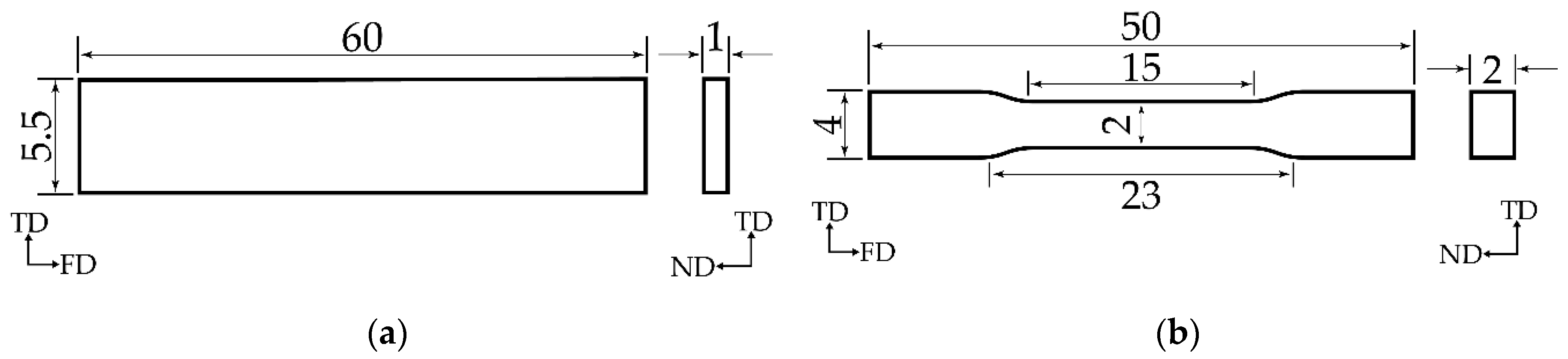
2.4.3. Flexural and Tensile Strength
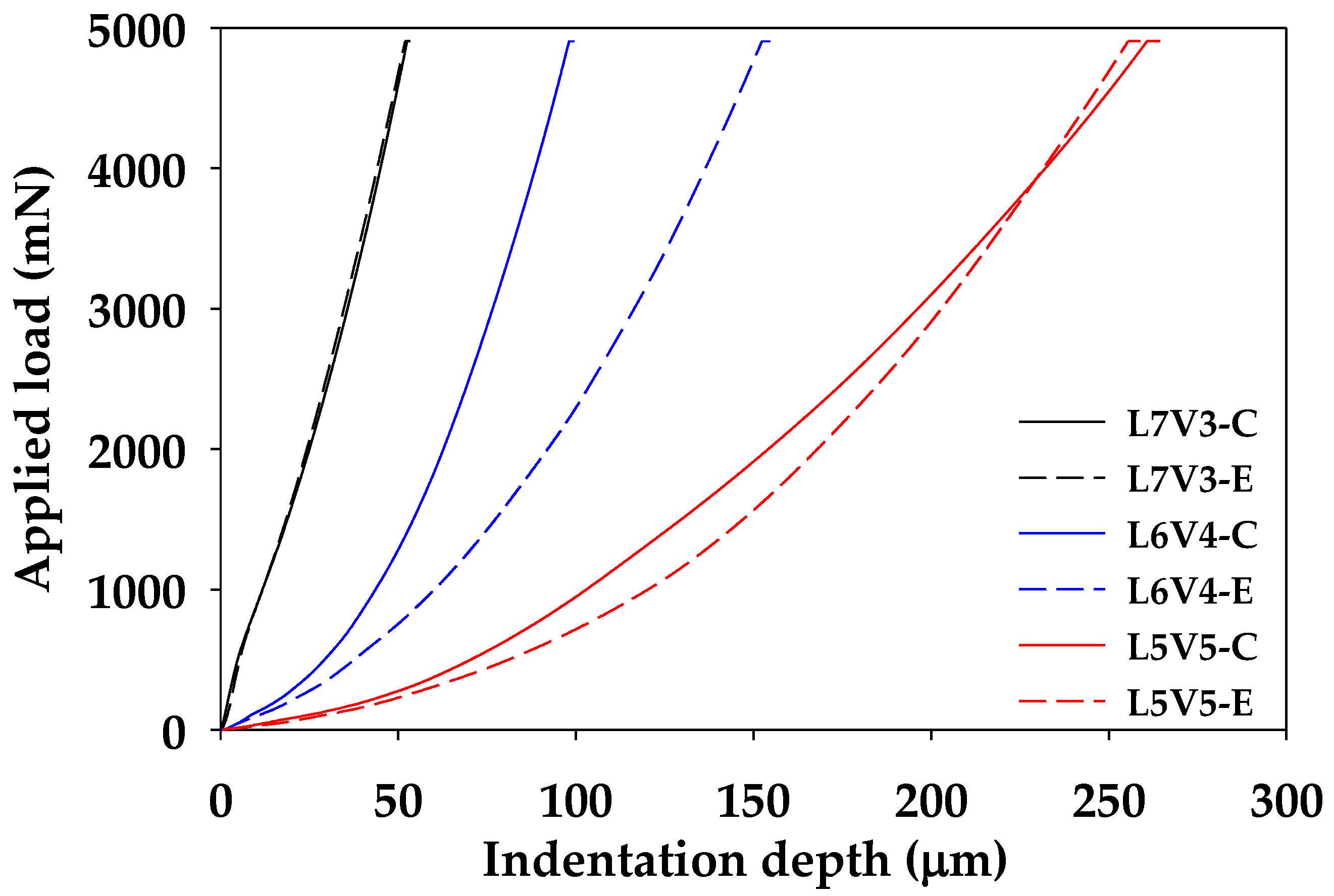
2.4.4. Indention
2.4.5. Density
2.4.6. Differential Scanning Calorimetry (DSC)
3. Results and Discussion
3.1. Rheology and Morphology
3.2. Thermal Properties
3.3. Mechanical Properties
4. Conclusions
Author Contributions
Funding
Conflicts of Interest
References
- Lam, K.H.; Nijenhuis, A.J.; Bartels, H.; Postema, A.R.; Jonkman, M.F.; Pennings, A.J.; Nieuwenhuis, P. Reinforced Poly(L-Lactic Acid) Fibres as Suture Material. J. Appl. Biomater. 1995, 6, 191–197. [Google Scholar] [CrossRef] [PubMed]
- Shah Mohammadi, M.; Bureau, M.N.; Nazhat, S.N. Polylactic Acid (PLA) Biomedical Foams for Tissue Engineering. In Biomedical Foams for Tissue Engineering Applications; Woodhead Publishing: Cambridge, UK, 2014; pp. 313–334. [Google Scholar] [CrossRef]
- Gavril, G.-L.; Wrona, M.; Bertella, A.; Świeca, M.; Râpă, M.; Salafranca, J.; Nerín, C. Influence of Medicinal and Aromatic Plants into Risk Assessment of a New Bioactive Packaging Based on Polylactic Acid (PLA). Food Chem. Toxicol. 2019, 132, 110662. [Google Scholar] [CrossRef] [PubMed]
- Qazi, T.H.; Rai, R.; Boccaccini, A.R. Tissue Engineering of Electrically Responsive Tissues Using Polyaniline Based Polymers: A Review. Biomaterials 2014, 35, 9068–9086. [Google Scholar] [CrossRef] [PubMed]
- Lowen, J.M.; Leach, J.K. Functionally Graded Biomaterials for Use as Model Systems and Replacement Tissues. Adv. Funct. Mater. 2020, 1909089. [Google Scholar] [CrossRef]
- Ou, J.; Liu, K.; Jiang, J.; Wilson, D.A.; Liu, L.; Wang, F.; Wang, S.; Tu, Y.; Peng, F. Micro-/Nanomotors toward Biomedical Applications: The Recent Progress in Biocompatibility. Small 2020, 1906184. [Google Scholar] [CrossRef]
- Furth, M.E.; Atala, A. Tissue Engineering. In Principles of Tissue Engineering; Academic Press: Waltham, MA, USA, 2014; pp. 83–123. [Google Scholar] [CrossRef]
- Tonelli, F.M.P.; de Cássia Oliveira Paiva, N.; de Medeiros, R.V.B.; Pinto, M.C.X.; Tonelli, F.C.P.; Resende, R.R. Tissue Engineering. In Current Developments in Biotechnology and Bioengineering; Elsevier: Cambridge, MA, USA, 2017; pp. 315–324. [Google Scholar] [CrossRef]
- Mathieu, L.M.; Montjovent, M.-O.; Bourban, P.-E.; Pioletti, D.P.; Månson, J.-A.E. Bioresorbable Composites Prepared by Supercritical Fluid Foaming. J. Biomed. Mater. Res. A 2005, 75, 89–97. [Google Scholar] [CrossRef]
- Gregor, A.; Filová, E.; Novák, M.; Kronek, J.; Chlup, H.; Buzgo, M.; Blahnová, V.; Lukášová, V.; Bartoš, M.; Nečas, A.; et al. Designing of PLA Scaffolds for Bone Tissue Replacement Fabricated by Ordinary Commercial 3D Printer. J. Biol. Eng. 2017, 11, 31. [Google Scholar] [CrossRef]
- Huang, A.; Jiang, Y.; Napiwocki, B.; Mi, H.; Peng, X.; Turng, L.-S. Fabrication of Poly(ε-Caprolactone) Tissue Engineering Scaffolds with Fibrillated and Interconnected Pores Utilizing Microcellular Injection Molding and Polymer Leaching. RSC Adv. 2017, 7, 43432–43444. [Google Scholar] [CrossRef] [Green Version]
- Izquierdo, R.; Garcia-Giralt, N.; Rodriguez, M.T.; Cáceres, E.; García, S.J.; Gómez Ribelles, J.L.; Monleón, M.; Monllau, J.C.; Suay, J. Biodegradable PCL Scaffolds with an Interconnected Spherical Pore Network for Tissue Engineering. J. Biomed. Mater. Res. A 2008, 85, 25–35. [Google Scholar] [CrossRef]
- Pan, Z.; Ding, J. Poly(Lactide-Co-Glycolide) Porous Scaffolds for Tissue Engineering and Regenerative Medicine. Interface Focus 2012, 2, 366–377. [Google Scholar] [CrossRef] [Green Version]
- McKenna, E.; Klein, T.J.; Doran, M.R.; Futrega, K. Integration of an Ultra-Strong Poly(Lactic-Co-Glycolic Acid) (PLGA) Knitted Mesh into a Thermally Induced Phase Separation (TIPS) PLGA Porous Structure to Yield a Thin Biphasic Scaffold Suitable for Dermal Tissue Engineering. Biofabrication 2019, 12, 015015. [Google Scholar] [CrossRef] [Green Version]
- Zhou, X.-H.; Wei, D.-X.; Ye, H.-M.; Zhang, X.; Meng, X.; Zhou, Q. Development of Poly(Vinyl Alcohol) Porous Scaffold with High Strength and Well Ciprofloxacin Release Efficiency. Mater. Sci. Eng. C 2016, 67, 326–335. [Google Scholar] [CrossRef] [PubMed]
- Li, G.; Qin, S.; Liu, X.; Zhang, D.; He, M. Structure and Properties of Nano-Hydroxyapatite/Poly(Butylene Succinate) Porous Scaffold for Bone Tissue Engineering Prepared by Using Ethanol as Porogen. J. Biomater. Appl. 2019, 33, 776–791. [Google Scholar] [CrossRef] [PubMed]
- Senatov, F.; Anisimova, N.; Kiselevskiy, M.; Kopylov, A.; Tcherdyntsev, V.; Maksimkin, A. Polyhydroxybutyrate/Hydroxyapatite Highly Porous Scaffold for Small Bone Defects Replacement in the Nonload-Bearing Parts. J. Bionic Eng. 2017, 14, 648–658. [Google Scholar] [CrossRef]
- Xiao, L.; Wang, B.; Yang, G.; Gauthier, M. Poly(Lactic Acid)-Based Biomaterials: Synthesis, Modification and Applications. In Biomedical Science, Engineering and Technology; Ghista, D.N., Ed.; IntechOpen: Rijeka, Croatia, 2012. [Google Scholar] [CrossRef] [Green Version]
- Dhandayuthapani, B.; Yoshida, Y.; Maekawa, T.; Kumar, D.S. Polymeric Scaffolds in Tissue Engineering Application: A Review. Int. J. Polym. Sci. 2011, 2011, 290602. [Google Scholar] [CrossRef]
- Kramschuster, A.; Turng, L.-S. An Injection Molding Process for Manufacturing Highly Porous and Interconnected Biodegradable Polymer Matrices for Use as Tissue Engineering Scaffolds. J. Biomed. Mater. Res. B Appl. Biomater. 2010, 92, 366–376. [Google Scholar] [CrossRef]
- Wang, X.; Li, W.; Kumar, V. A Method for Solvent-Free Fabrication of Porous Polymer Using Solid-State Foaming and Ultrasound for Tissue Engineering Applications. Biomaterials 2006, 27, 1924–1929. [Google Scholar] [CrossRef]
- An, J.; Chua, C.K.; Leong, K.F.; Chen, C.-H.; Chen, J.-P. Solvent-Free Fabrication of Three Dimensionally Aligned Polycaprolactone Microfibers for Engineering of Anisotropic Tissues. Biomed. Microdevices 2012, 14, 863–872. [Google Scholar] [CrossRef]
- Aramwit, P.; Ratanavaraporn, J.; Ekgasit, S.; Tongsakul, D.; Bang, N. A Green Salt-Leaching Technique to Produce Sericin/PVA/Glycerin Scaffolds with Distinguished Characteristics for Wound-Dressing Applications: Salt-Leached Sericin/PVA/Glycerin Scaffolds as a Wound Dressing. J. Biomed. Mater. Res. B Appl. Biomater. 2015, 103, 915–924. [Google Scholar] [CrossRef]
- Zhang, K.; Wang, Y.; Jiang, J.; Wang, X.; Hou, J.; Sun, S.; Li, Q. Fabrication of Highly Interconnected Porous Poly(ε-Caprolactone) Scaffolds with Supercritical CO2 Foaming and Polymer Leaching. J. Mater. Sci. 2019, 54, 5112–5126. [Google Scholar] [CrossRef]
- Thadavirul, N.; Pavasant, P.; Supaphol, P. Development of Polycaprolactone Porous Scaffolds by Combining Solvent Casting, Particulate Leaching, and Polymer Leaching Techniques for Bone Tissue Engineering: Development of Polycaprolactone Porous Scaffolds. J. Biomed. Mater. Res. A 2014, 102, 3379–3392. [Google Scholar] [CrossRef] [PubMed]
- Kim, H.; Yang, G.H.; Kim, G. Three-Dimensional Gelatin/PVA Scaffold with Nanofibrillated Collagen Surface for Applications in Hard-Tissue Regeneration. Int. J. Biol. Macromol. 2019, 135, 21–28. [Google Scholar] [CrossRef] [PubMed]
- Sun, X.-R.; Cao, Z.-Q.; Bao, R.-Y.; Liu, Z.; Xie, B.-H.; Yang, M.-B.; Yang, W. A Green and Facile Melt Approach for Hierarchically Porous Polylactide Monoliths Based on Stereocomplex Crystallite Network. ACS Sustain. Chem. Eng. 2017, 5, 8334–8343. [Google Scholar] [CrossRef]
- Zhang, X.; Wang, X.; Liu, X.; Lv, C.; Wang, Y.; Zheng, G.; Liu, H.; Liu, C.; Guo, Z.; Shen, C. Porous Polyethylene Bundles with Enhanced Hydrophobicity and Pumping Oil-Recovery Ability via Skin-Peeling. ACS Sustain. Chem. Eng. 2018, 6, 12580–12585. [Google Scholar] [CrossRef]
- Ye, M.; Mohanty, P.; Ghosh, G. Morphology and Properties of Poly Vinyl Alcohol (PVA) Scaffolds: Impact of Process Variables. Mater. Sci. Eng. C 2014, 42, 289–294. [Google Scholar] [CrossRef] [PubMed]
- Pötschke, P.; Paul, D.R. Formation of Co-Continuous Structures in Melt-Mixed Immiscible Polymer Blends. J. Macromol. Sci.-Polym. Rev. 2003, 43, 87–141. [Google Scholar] [CrossRef]
- Willemse, R.C.; Posthuma De Boer, A.; Van Dam, J.; Gotsis, A.D. Co-Continuous Morphologies in Polymer Blends: A New Model. Polymer 1998, 39, 5879–5887. [Google Scholar] [CrossRef]
- Scaffaro, R.; Lopresti, F.; Botta, L.; Rigogliuso, S.; Ghersi, G. Melt Processed PCL/PEG Scaffold with Discrete Pore Size Gradient for Selective Cellular Infiltration. Macromol. Mater. Eng. 2016, 301, 182–190. [Google Scholar] [CrossRef]
- Ghavidel Mehr, N.; Li, X.; Ariganello, M.B.; Hoemann, C.D.; Favis, B.D. Poly(ε-Caprolactone) Scaffolds of Highly Controlled Porosity and Interconnectivity Derived from Co-Continuous Polymer Blends: Model Bead and Cell Infiltration Behavior. J. Mater. Sci. Mater. Med. 2014, 25, 2083–2093. [Google Scholar] [CrossRef]
- Salerno, A.; Zeppetelli, S.; Di Maio, E.; Iannace, S.; Netti, P.A. Architecture and Properties of Bi-Modal Porous Scaffolds for Bone Regeneration Prepared via Supercritical CO2 Foaming and Porogen Leaching Combined Process. J. Supercrit. Fluids 2012, 67, 114–122. [Google Scholar] [CrossRef]
- Gao, M.; Ren, Z.; Yan, S.; Sun, J.; Chen, X. An Optical Microscopy Study on the Phase Structure of Poly(L-Lactide Acid)/Poly(Propylene Carbonate) Blends. J. Phys. Chem. B 2012, 116, 9832–9837. [Google Scholar] [CrossRef] [PubMed]
- Tsuji, H.; Muramatsu, H. Blends of Aliphatic Polyesters. IV. Morphology, Swelling Behavior, and Surface and Bulk Properties of Blends from Hydrophobic Poly(L-Lactide) and Hydrophilic Poly(Vinyl Alcohol). J. Appl. Polym. Sci. 2001, 81, 2151–2160. [Google Scholar] [CrossRef]
- Thomas, S.; Harrats, C.; Groeninckx, G. Micro- and Nanostructured Polymer Blends: State of the Art Challenges, and Future Prospects. In Micro- and Nanostructured Multiphase Polymer Blend Systems: Phase Morphology and Interfaces; CRC Press: Boca Raton, FL, USA, 2006; pp. 1–33. [Google Scholar] [CrossRef]
- Kappert, E.J.; Raaijmakers, M.J.T.; Tempelman, K.; Cuperus, F.P.; Ogieglo, W.; Benes, N.E. Swelling of 9 Polymers Commonly Employed for Solvent-Resistant Nanofiltration Membranes: A Comprehensive Dataset. J. Membr. Sci. 2019, 569, 177–199. [Google Scholar] [CrossRef] [Green Version]
- Alfrey, T., Jr.; Gurnee, E.F.; Lloyd, W.G. Diffusion in Glassy Polymers. J. Polym. Sci. Part C Polym. Symp. 1966, 12, 249–261. [Google Scholar] [CrossRef]
- Silberberg, A. The Role of Matrix Mechanical Stress in Swelling Equilibrium and Transport through Networks. Macromolecules 1980, 13, 742–748. [Google Scholar] [CrossRef]
- Ouyang, H.; Lee, W.H.; Shih, M.C. Three Stages of Crystallization in Poly(Ethylene Terephthalate) during Mass Transport. Macromolecules 2002, 35, 8428–8432. [Google Scholar] [CrossRef]
- Bärwinkel, S.; Seidel, A.; Hobeika, S.; Hufen, R.; Mörl, M.; Altstädt, V. Morphology Formation in PC/ABS Blends during Thermal Processing and the Effect of the Viscosity Ratio of Blend Partners. Materials 2016, 9, 659. [Google Scholar] [CrossRef] [PubMed] [Green Version]
- Fox, T.G. Influence of Diluent and of Copolymer Composition on the Glass Temperature of a Polymer System. Bull. Am. Phys. Soc. 1956, 1, 123. [Google Scholar]
- Zhang, J.; Tashiro, K.; Tsuji, H.; Domb, A.J. Disorder-to-Order Phase Transition and Multiple Melting Behavior of Poly(L-Lactide) Investigated by Simultaneous Measurements of WAXD and DSC. Macromolecules 2008, 41, 1352–1357. [Google Scholar] [CrossRef]
- Iñiguez-Franco, F.; Auras, R.; Burgess, G.; Holmes, D.; Fang, X.; Rubino, M.; Soto-Valdez, H. Concurrent Solvent Induced Crystallization and Hydrolytic Degradation of PLA by Water-Ethanol Solutions. Polymer 2016, 99, 315–323. [Google Scholar] [CrossRef] [Green Version]
- Shuai, X.; He, Y.; Asakawa, N.; Inoue, Y. Miscibility and Phase Structure of Binary Blends of Poly(L-Lactide) and Poly(Vinyl Alcohol). J. Appl. Polym. Sci. 2001, 81, 762–772. [Google Scholar] [CrossRef]


| Code | PLA (wt.%) | PVA (wt.%) |
|---|---|---|
| L7V3 | 70 | 30 |
| L6V4 | 60 | 40 |
| L5V5 | 50 | 50 |
| Code | Tg (°C) | Tcc (°C) | Tm,PVA (°C) | Tm,PLA (°C) | Xc (%) |
|---|---|---|---|---|---|
| PLA | 62.2 | 108.8 | - | 169.0 | 12.6 |
| PLA7E 1 | 62.0 | 110.3 | - | 168.6 | 12.4 |
| PLA7C 1 | 61.8 | 109.6 | - | 168.7 | 12.3 |
| PVA | 57.0 | - | 150.3 | - | 9.6 |
| L7V3 | 61.4 | 106.0 | 152.0 | 167.4 | 9.3 |
| L6V4 | 61.3 | 108.2 | 153.2 | 167.2 | 9.2 |
| L5V5 | 60.7 | 102.4 | 152.1 | 165.9 | 9.7 |
| Code | Flexural Properties | Tensile Properties | ||||
|---|---|---|---|---|---|---|
| Modulus (GPa) | Strength (MPa) | Displacement (mm) | Modulus (GPa) | Strength (MPa) | Elongation at Break (%) | |
| PLA | 2.7 | 100.9 | 10.1 | 2.9 | 68.8 | 10.1 |
| PLA7 1 | 2.5 | 95.7 | 8.4 | 3.0 | 69.5 | 7.3 |
| PVA | 5.2 | 120.8 | 9.9 | 3.0 | 116.1 | 45.9 |
| L7V3 | 2.7 | 75.9 | 3.8 | 2.6 | 66.1 | 3.8 |
| L6V4 | 2.6 | 73.7 | 4.1 | 2.9 | 67.0 | 3.9 |
| L5V5 | 2.7 | 67.5 | 3.1 | 3.1 | 62.3 | 3.3 |
| Code | Porosity (%) | Flexural Properties | Tensile Properties | |||
|---|---|---|---|---|---|---|
| Modulus (GPa) | Strength (MPa) | Modulus (GPa) | Strength (MPa) | Elongation at Break (%) | ||
| L7V3 | 0.0 | 2.7 | 75.9 | 2.6 | 66.0 | 3.8 |
| 0.5 | 2.5 | 73.7 | 2.8 | 64.4 | 3.7 | |
| 0.3 | 2.2 | 64.5 | 2.7 | 66.9 | 3.7 | |
| 0.7 | 1.9 | 54.1 | 2.6 | 61.9 | 3.6 | |
| 1.6 | 1.7 | 51.3 | 2.6 | 66.2 | 3.7 | |
| L6V4 | 0.0 | 2.6 | 73.7 | 2.9 | 67.0 | 3.9 |
| 6.8 | 1.5 | 41.5 | 2.9 | 68.1 | 3.6 | |
| 13.4 | 1.3 | 42.0 | 2.7 | 60.9 | 3.4 | |
| 19.0 | 1.4 | 35.6 | 2.3 | 47.2 | 3.3 | |
| 25.0 | 1.3 | 29.1 | 2.2 | 48.9 | 3.3 | |
| L5V5 | 0.0 | 2.7 | 67.5 | 3.1 | 62.3 | 3.3 |
| 13.8 | 0.9 | 28.6 | 2.0 | 40.0 | 2.4 | |
| 32.0 | 0.6 | 16.1 | 0.8 | 10.2 | 1.9 | |
| 42.4 | 0.5 | 15.5 | 0.8 | 11.4 | 2.2 | |
| 43.4 | 0.3 | 12.4 | 0.6 | 8.2 | 2 | |
© 2020 by the authors. Licensee MDPI, Basel, Switzerland. This article is an open access article distributed under the terms and conditions of the Creative Commons Attribution (CC BY) license (http://creativecommons.org/licenses/by/4.0/).
Share and Cite
Chuaponpat, N.; Ueda, T.; Ishigami, A.; Kurose, T.; Ito, H. Morphology, Thermal and Mechanical Properties of Co-Continuous Porous Structure of PLA/PVA Blends by Phase Separation. Polymers 2020, 12, 1083. https://doi.org/10.3390/polym12051083
Chuaponpat N, Ueda T, Ishigami A, Kurose T, Ito H. Morphology, Thermal and Mechanical Properties of Co-Continuous Porous Structure of PLA/PVA Blends by Phase Separation. Polymers. 2020; 12(5):1083. https://doi.org/10.3390/polym12051083
Chicago/Turabian StyleChuaponpat, Natthapong, Tsubasa Ueda, Akira Ishigami, Takashi Kurose, and Hiroshi Ito. 2020. "Morphology, Thermal and Mechanical Properties of Co-Continuous Porous Structure of PLA/PVA Blends by Phase Separation" Polymers 12, no. 5: 1083. https://doi.org/10.3390/polym12051083