
Effect of Core Architecture on Charpy Impact and Compression Properties of Tufted Sandwich Structural Composites


Abstract
:1. Introduction
2. Materials and Methods
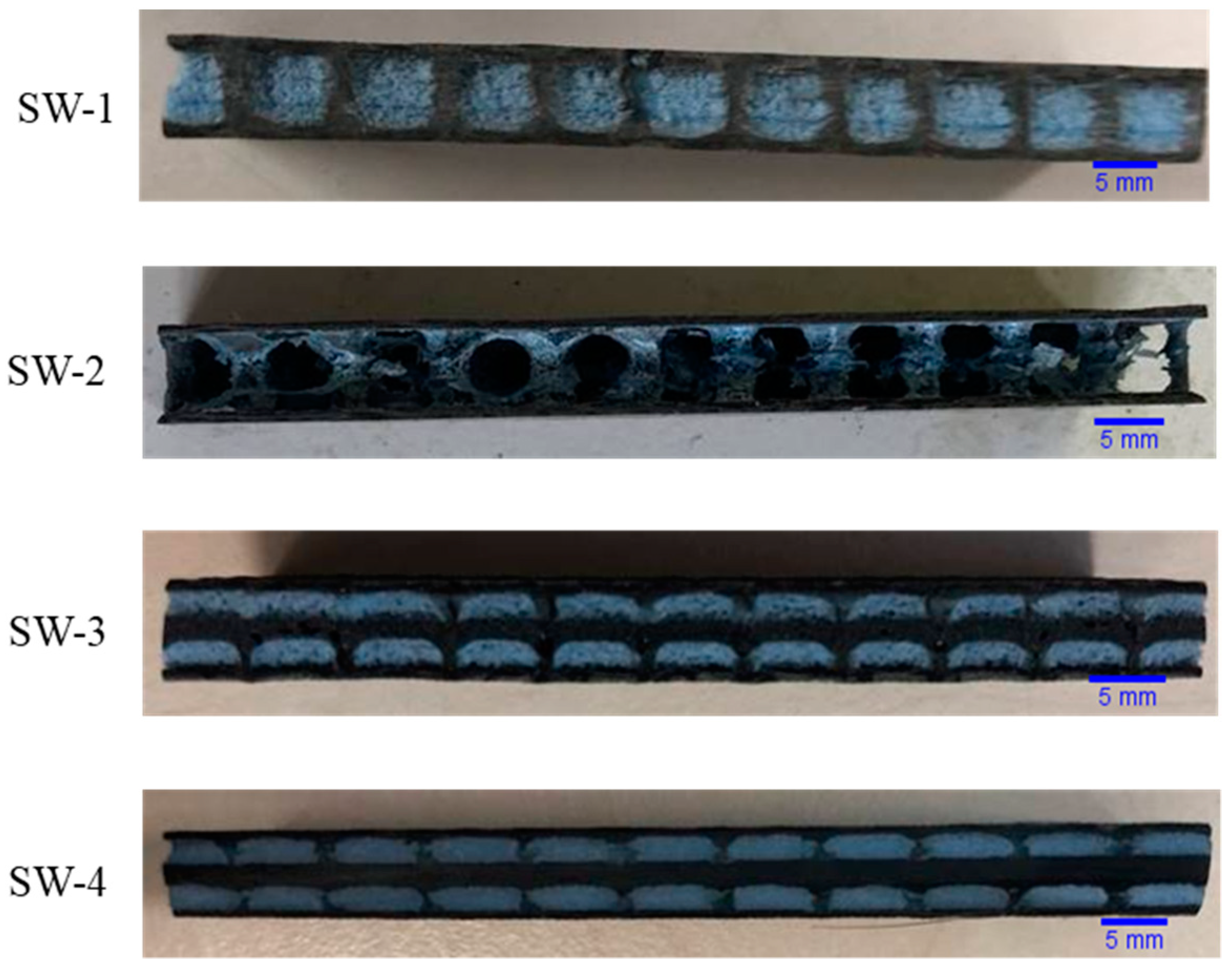
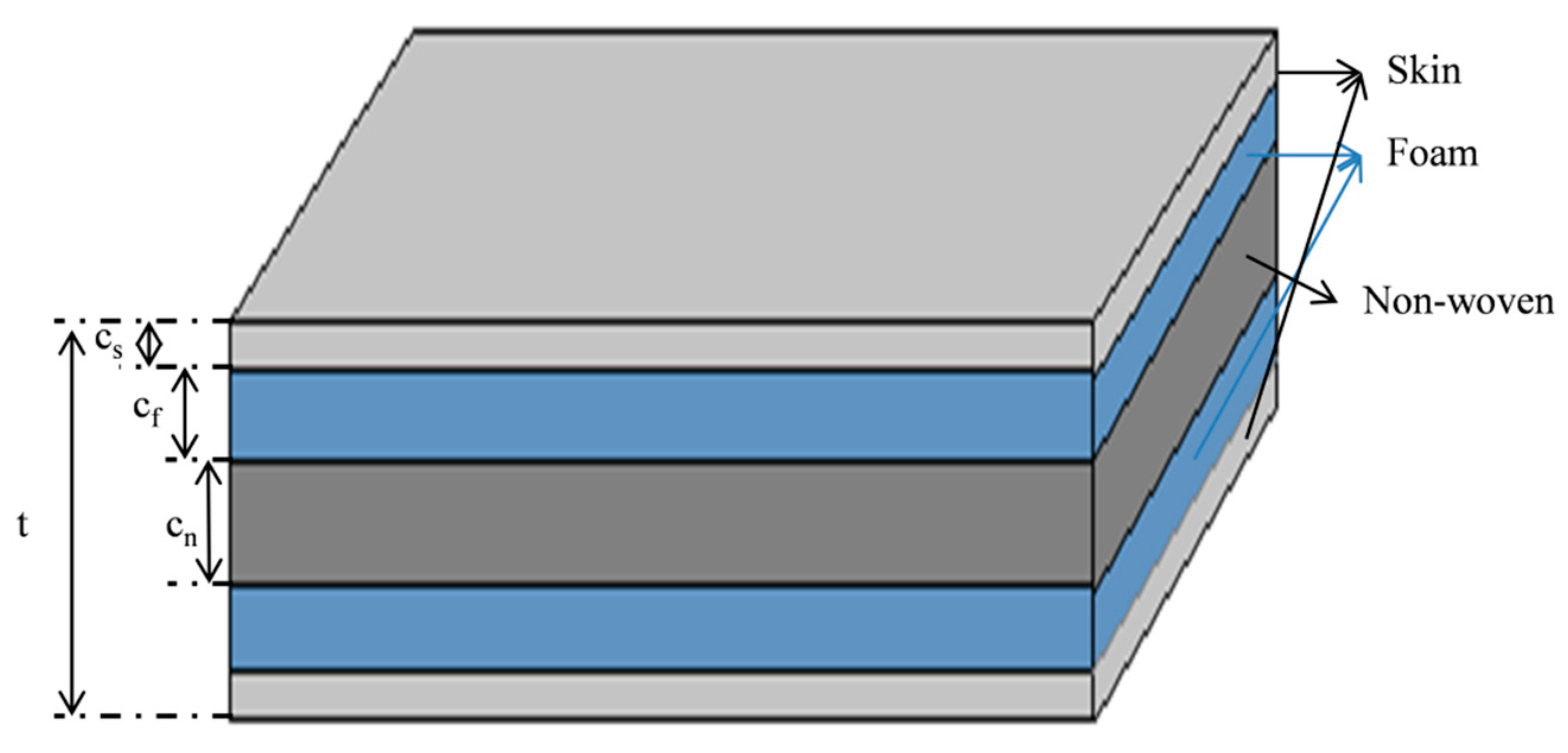
2.1. Process of Sandwich Composite Manufacturing
2.2. Experimental Methods
2.2.1. Flatwise CompressiveTtest
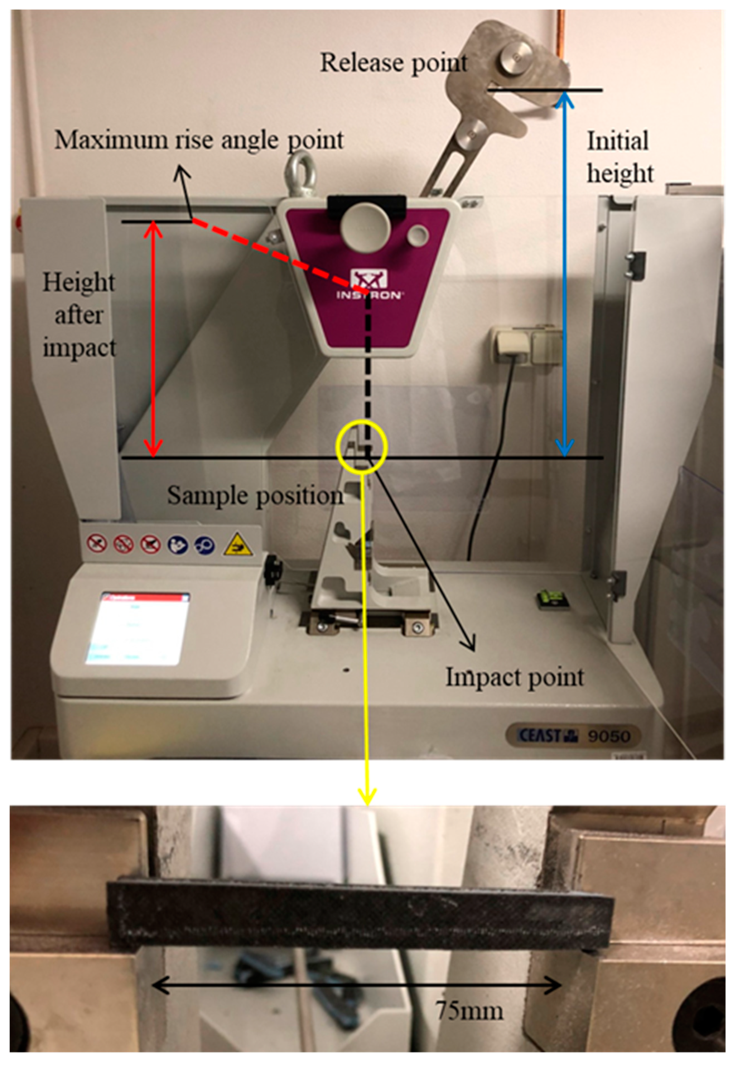
2.2.2. Charpy Impact Test
3. Results
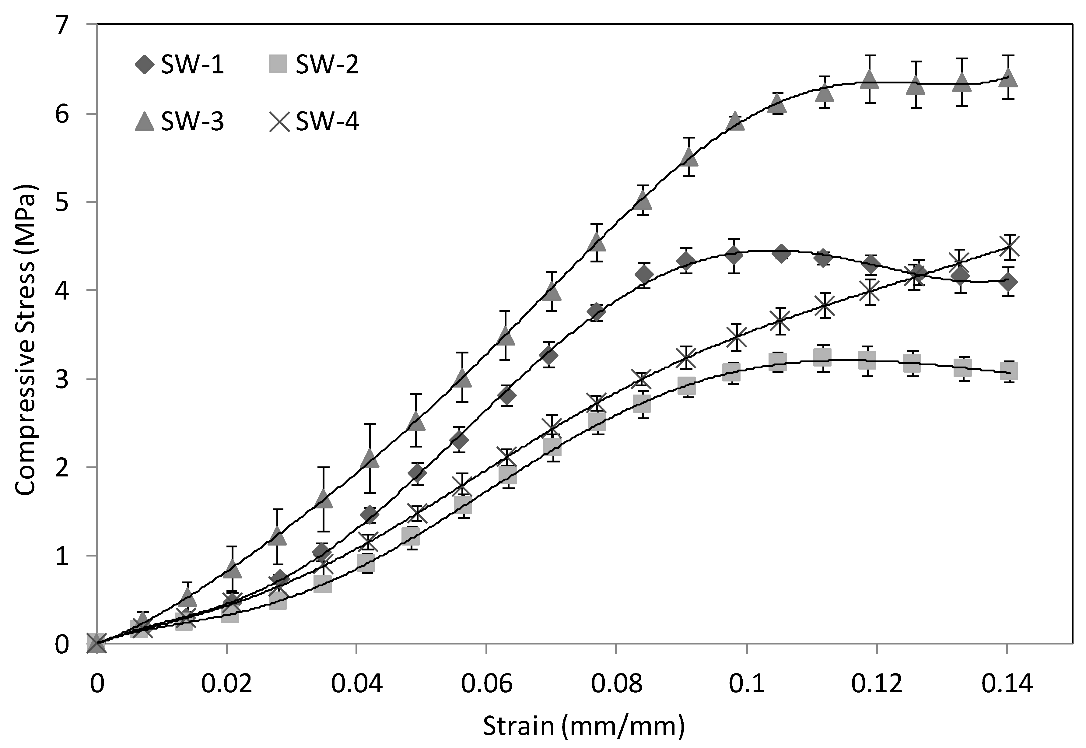
3.1. Compression
3.2. Charpy Impact
4. Conclusions
- Improvement of the manufacturing process to strictly control the resin content of the sample.
- A new observation method to determine the status of each reinforcement and the failure mode.
- Improvement of the calculation model to accurately determine the compressive strength and modulus.
Author Contributions
Funding
Data Availability Statement
Acknowledgments
Conflicts of Interest
References
- Al-fatlawi, A.; Jármai, K.; Kovács, G. Optimal design of a fiber-reinforced plastic composite sandwich structure for the base plate of aircraft pallets in order to reduce weight. Polymers (Basel) 2021, 13, 834. [Google Scholar] [CrossRef]
- Mouritz, A.P. Compression properties of z-pinned sandwich composites. J. Mater. Sci. 2006, 41, 5771–5774. [Google Scholar] [CrossRef]
- Nanayakkara, A.; Feih, S.; Mouritz, A.P. Experimental analysis of the through-thickness compression properties of z-pinned sandwich composites. Compos. Part A Appl. Sci. Manuf. 2011, 42, 1673–1680. [Google Scholar] [CrossRef]
- Hu, Y.; Zhu, J.; Wang, J.; Wu, Y. Interfacial Failure in Stitched Foam Sandwich Composites. Materials (Basel) 2021, 14, 2275. [Google Scholar] [CrossRef] [PubMed]
- Du, L.; Jiao, G. Indentation study of Z-pin reinforced polymer foam core sandwich structures. Compos. Part A Appl. Sci. Manuf. 2009, 40, 822–829. [Google Scholar] [CrossRef]
- Nanayakkara, A.; Feih, S.; Mouritz, A.P. Experimental impact damage study of a z-pinned foam core sandwich composite. J. Sandw. Struct. Mater. 2012, 14, 469–486. [Google Scholar] [CrossRef]
- Kaya, G.; Selver, E. Impact resistance of Z-pin-reinforced sandwich composites. J. Compos. Mater. 2019, 53, 3681–3699. [Google Scholar] [CrossRef]
- M’membe, B.; Gannon, S.; Yasaee, M.; Hallett, S.R.; Partridge, I.K. Mode II delamination resistance of composites reinforced with inclined Z-pins. Mater. Des. 2016, 94, 565–572. [Google Scholar] [CrossRef] [Green Version]
- Knopp, A.; Scharr, G. Tensile Properties of Z-Pin Reinforced Laminates with Circumferentially Notched Z-Pins. J. Compos. Sci. 2020, 4, 78. [Google Scholar] [CrossRef]
- Tekalur, S.A.; Bogdanovich, A.E.; Shukla, A. Shock loading response of sandwich panels with 3-D woven E-glass composite skins and stitched foam core. Compos. Sci. Technol. 2009, 69, 736–753. [Google Scholar] [CrossRef]
- Mouritz, A.P.; Bannister, M.K.; Falzon, P.J.; Leong, K.H. Review of applications for advanced three-dimensional fibre textile composites. Compos. Part A Appl. Sci. Manuf. 1999, 30, 1445–1461. [Google Scholar] [CrossRef]
- Gereke, T.; Cherif, C. A review of numerical models for 3D woven composite reinforcements. Compos. Struct. 2019, 209, 60–66. [Google Scholar] [CrossRef]
- Lascoup, B.; Aboura, Z.; Khellil, K.; Benzeggagh, M. Prediction of out-of-plane behavior of stitched sandwich structure. Compos. Part B Eng. 2012, 43, 2915–2920. [Google Scholar] [CrossRef]
- Lascoup, B.; Aboura, Z.; Khellil, K.; Benzeggagh, M. Homogenization of the core layer in stitched sandwich structures. Compos. Sci. Technol. 2010, 70, 350–355. [Google Scholar] [CrossRef]
- Zheng, X.T.; Zhang, J.F.; Yang, F.; Chai, Y.N.; Li, Y. Experimental and analytical study on the mechanical behavior of stitched sandwich composite panel with a foam core. Adv. Mater. Res. 2008, 33–37, 477–482. [Google Scholar] [CrossRef]
- Hao, S.; Wang, P.; Legrand, X.; Liu, L.; Soulat, D. Influence of the tufting pattern on the formability of tufted multi-layered preforms. Compos. Struct. 2019, 228, 111356. [Google Scholar]
- Liu, L.S.; Zhang, T.; Wang, P.; Legrand, X.; Soulat, D. Influence of the tufting yarns on formability of tufted 3-Dimensional composite reinforcement. Compos. Part A Appl. Sci. Manuf. 2015. [Google Scholar] [CrossRef]
- Dell’Anno, G.; Treiber, J.W.G.; Partridge, I.K. Manufacturing of composite parts reinforced through-thickness by tufting. Robot. Comput. Integr. Manuf. 2016, 37, 262–272. [Google Scholar] [CrossRef]
- Che, L.; Xu, G.D.; Zeng, T.; Cheng, S.; Zhou, X.W.; Yang, S.C. Compressive and shear characteristics of an octahedral stitched sandwich composite. Compos. Struct. 2014, 112, 179–187. [Google Scholar] [CrossRef]
- May-Pat, A.; Avilés, F.; Aguilar, J. Mechanical properties of sandwich panels with perforated foam cores. J. Sandw. Struct. Mater. 2011, 13, 427–444. [Google Scholar] [CrossRef]
- Jijun, H.; Zuoguang, Z.; Min, L.; Zhijie, S.; Yizuo, G. The influence of preparing method on novel x-truss/foam sandwich structure. J. Reinf. Plast. Compos. 2009, 28, 1553–1565. [Google Scholar] [CrossRef]
- Yalkin, H.E.; Icten, B.M.; Alpyildiz, T. Enhanced mechanical performance of foam core sandwich composites with through the thickness reinforced core. Compos. Part B Eng. 2015, 79, 383–391. [Google Scholar] [CrossRef]
- Zhou, D.; Stronge, W.J. Mechanical properties of fibrous core sandwich panels. Int. J. Mech. Sci. 2005, 47, 775–798. [Google Scholar] [CrossRef]
- Long, D.; Guiqiong, J.; Tao, H. Investigation of the effect of Z-pin reinforcement on the collapse of foam-cored sandwich panels. J. Reinf. Plast. Compos. 2008, 27, 1211–1224. [Google Scholar] [CrossRef]
- Cartié, D.D.; Fleck, N.A. The effect of pin reinforcement upon the through-thickness compressive strength of foam-cored sandwich panels. Compos. Sci. Technol. 2003, 63, 2401–2409. [Google Scholar] [CrossRef]
- Nishi, Y.; Tsuchikura, N.; Nanba, S.; Yamamoto, T.; Faudree, M.C. Charpy impact of sandwich structural composites (CFRP/PC/CFRP) of polycarbonate (PC) cores covered with carbon fiber cross textile reinforced epoxy polymer (CFRP) thin sheets as a function of temperature. Mater. Trans. 2012, 53, 1288–1294. [Google Scholar] [CrossRef] [Green Version]
- Srivastava, V.K. Impact Behaviour of Sandwich GFRP-Foam-GFRP Composites. Int. J. Compos. Mater. 2012, 2, 63–66. [Google Scholar] [CrossRef]
- Alsubari, S.; Zuhri, M.Y.M.; Sapuan, S.M.; Ishak, M.R.; Ilyas, R.A.; Asyraf, M.R.M. Potential of natural fiber reinforced polymer composites in sandwich structures: A review on its mechanical properties. Polymers (Basel) 2021, 13, 423. [Google Scholar] [CrossRef]
- ASTM C365-16. Standard Test Method for Flatwise Compressive Properties of Sandwich Cores; ASTM International: West Conshohocken, PA, USA, 2016. [Google Scholar]
- ISO 179-1: 2010. Plastics—Determination of Charpy Impact Properties—Part 1: Non-Instrumented Impact Test; ISO: Geneva, Switzerland, 2010. [Google Scholar]
- Tita, V.; Caliri, M.F. Numerical simulation of anisotropic polymeric foams. Lat. Am. J. Solids Struct. 2012, 9, 259–279. [Google Scholar] [CrossRef] [Green Version]
- Mao, N.; Russell, S.J. Fibre to Fabric: Nonwoven Fabrics; Elsevier Ltd.: Amsterdam, The Netherlands, 2015; ISBN 9780857095619. [Google Scholar]
- Albooyeh, A.; Eskandarzadeh, S.; Mousavi, A. Influence of different foaming conditions on the mechanical, physical, and structural properties of polypropylene foam. Mech. Adv. Compos. Struct. 2019, 6, 225–237. [Google Scholar] [CrossRef]
- Junaedi, H.; Albahkali, E.; Baig, M.; Dawood, A.; Almajid, A. Ductile to Brittle Transition of Short Carbon Fiber-Reinforced Polypropylene Composites. Adv. Polym. Technol. 2020, 2020, 1–10. [Google Scholar] [CrossRef]


| Sample ID | Core Material | TT Reinforcement | Thickness (mm) |
|---|---|---|---|
| SW-1 | 3 layers of foam | Yarn/resin cylinders | 7.27 ± 0.29 |
| SW-2 | Hollow | 6.75 ± 0.16 | |
| SW-3 | Foam/Non-woven | 6.58 ± 0.17 | |
| SW-4 | Pure resin cylinders | 6.46 ± 0.15 |
| Raw Materials | Weight Parameter | Young’s Modulus (GPa) | Elongation at Break |
|---|---|---|---|
| Skin fabric | 285 g/m2 | 24.4 | 3.5% |
| Non-woven | 210 g/m2 | 15.8 | - |
| Tufting yarn | Linear density: 2 × 67 Tex | 240.0 | 1.7% |
| Foam | Density: 0.01 g/cm3 | 1.6 × 10⁻² | 6.7% |
| Epoxy resin | Density: 1.2 g/cm3 | 2.9 | 1.7% |
| Sample ID | Compressive Strength (MPa) | Specific Compressive Strength (kN·m/kg) | CV (Coefficient of Variation) | Compressive Modulus (MPa) | Specific Compressive Modulus (kN·m/kg) |
|---|---|---|---|---|---|
| SW-1 | 4.42 | 9.52 | 2.78% | 64.32 | 138.61 |
| SW-2 | 3.24 | 7.60 | 5.48% | 45.17 | 95.70 |
| SW-3 | 6.40 | 9.27 | 3.40% | 67.23 | 97.46 |
| SW-4 | 3.45 | 5.55 | 6.09% | 44.82 | 72.17 |
Publisher’s Note: MDPI stays neutral with regard to jurisdictional claims in published maps and institutional affiliations. |
© 2021 by the authors. Licensee MDPI, Basel, Switzerland. This article is an open access article distributed under the terms and conditions of the Creative Commons Attribution (CC BY) license (https://creativecommons.org/licenses/by/4.0/).
Share and Cite
Chen, C.; Wang, P.; Legrand, X. Effect of Core Architecture on Charpy Impact and Compression Properties of Tufted Sandwich Structural Composites. Polymers 2021, 13, 1665. https://doi.org/10.3390/polym13101665
Chen C, Wang P, Legrand X. Effect of Core Architecture on Charpy Impact and Compression Properties of Tufted Sandwich Structural Composites. Polymers. 2021; 13(10):1665. https://doi.org/10.3390/polym13101665
Chicago/Turabian StyleChen, Chen, Peng Wang, and Xavier Legrand. 2021. "Effect of Core Architecture on Charpy Impact and Compression Properties of Tufted Sandwich Structural Composites" Polymers 13, no. 10: 1665. https://doi.org/10.3390/polym13101665