
Analytical Review on Eccentric Axial Compression Behavior of Short and Slender Circular RC Columns Strengthened Using CFRP


Abstract
:1. Introduction
2. Research Significance
3. Experimental Tests
4. Model Development
4.1. Effect of Confinement by FRP Wraps
4.2. Effect of Longitudinal FRP Wraps
4.3. Effect of Internal Steel Reinforcement r
4.4. Peak Axial Strength and Strain
4.5. Analytical Prediction of Slenderness Limit
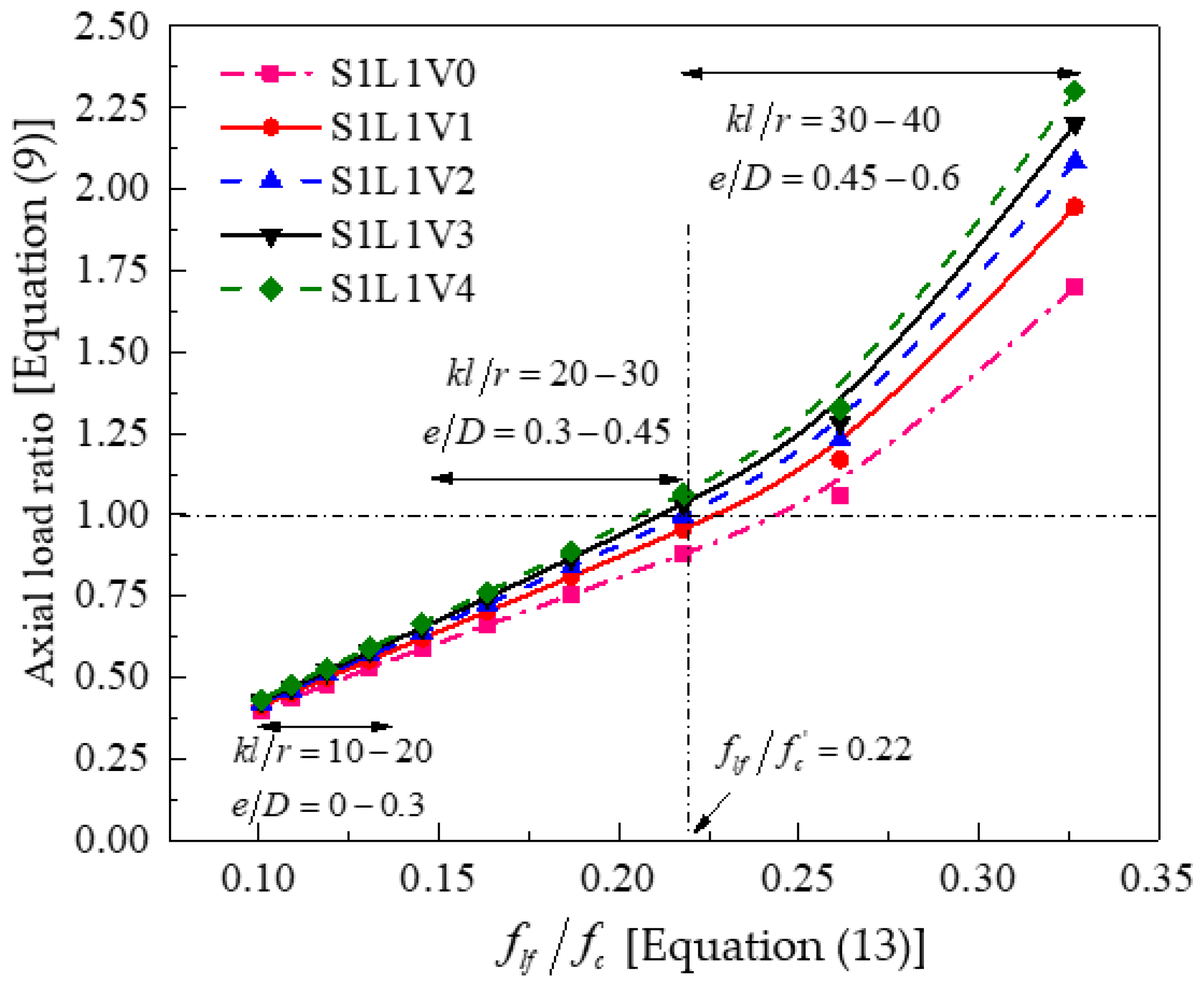
4.6. Minimum Amount of FRP for Adequate Confinement
4.7. Complete Stress–Strain Model
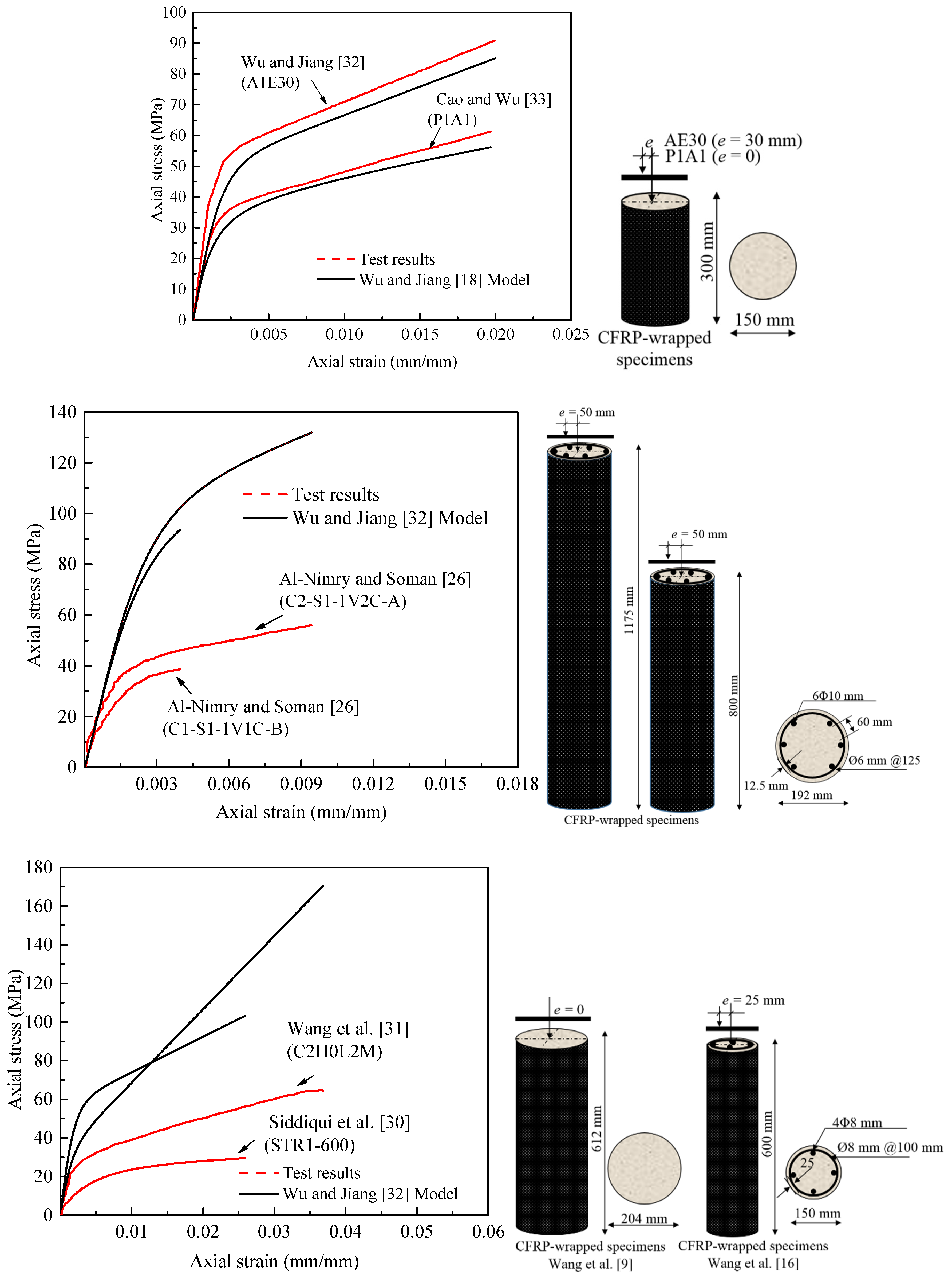
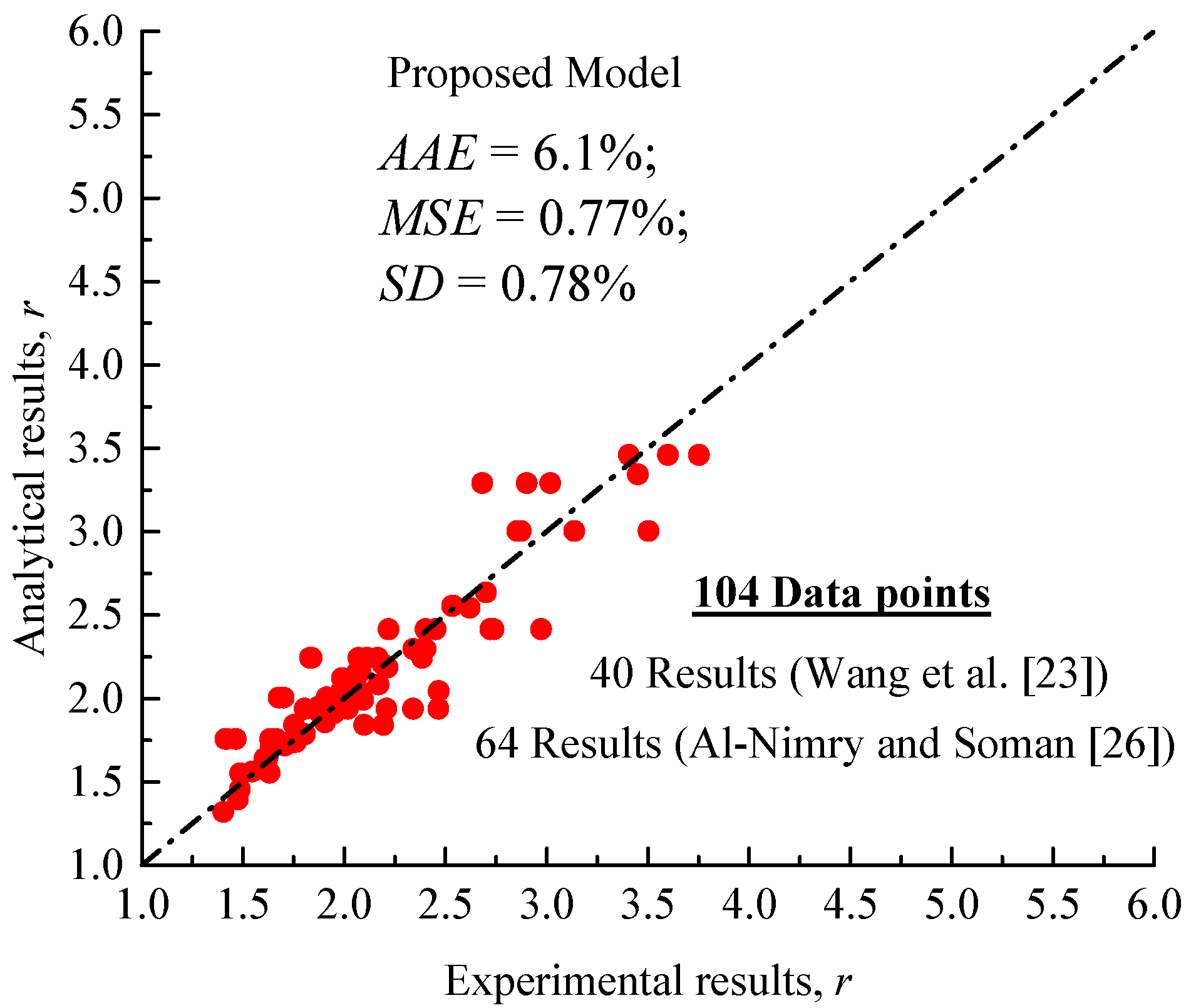
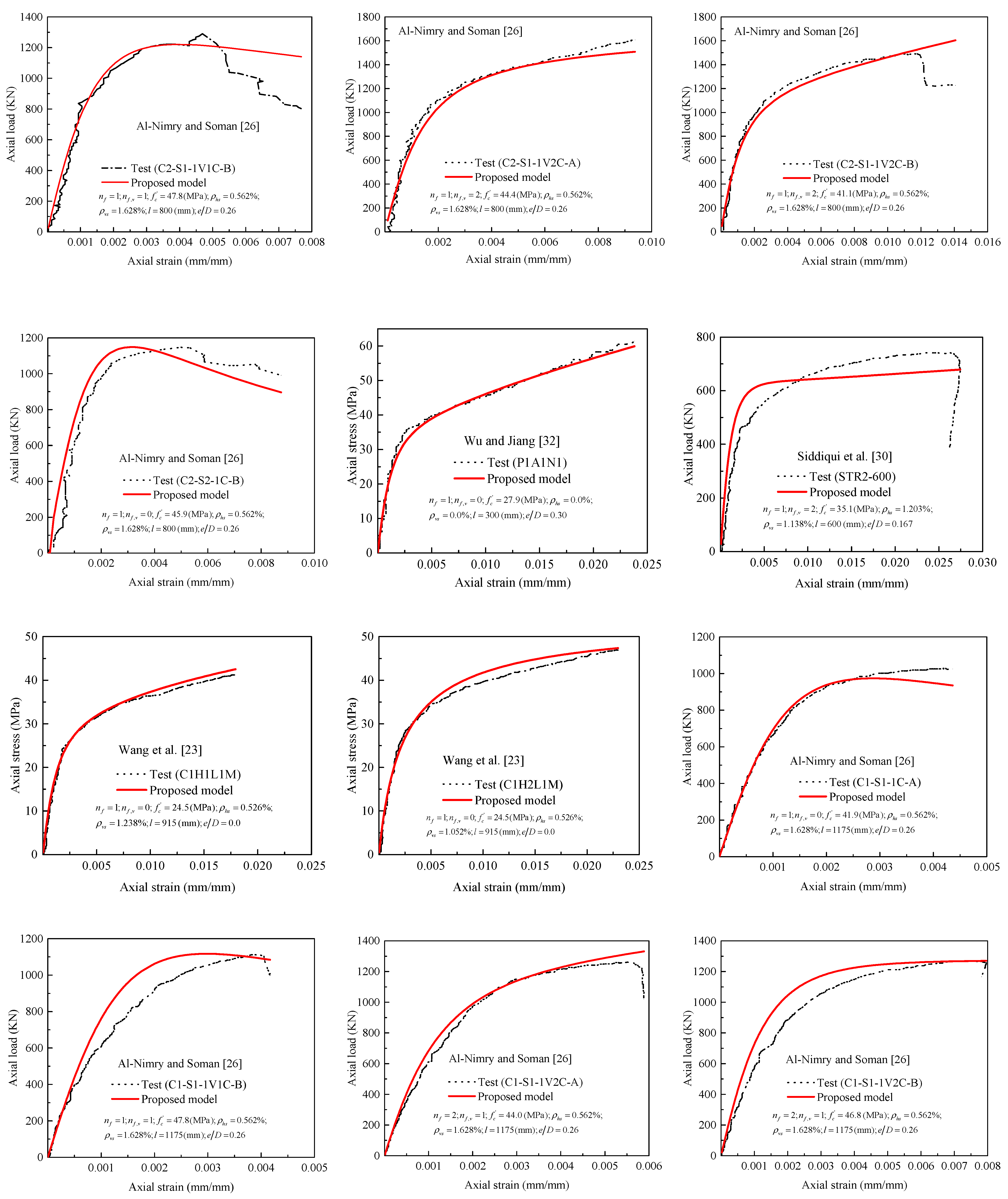
4.8. Performance of the Proposed Stress-Strain Model
5. P–M Interaction Diagrams
5.1. Background
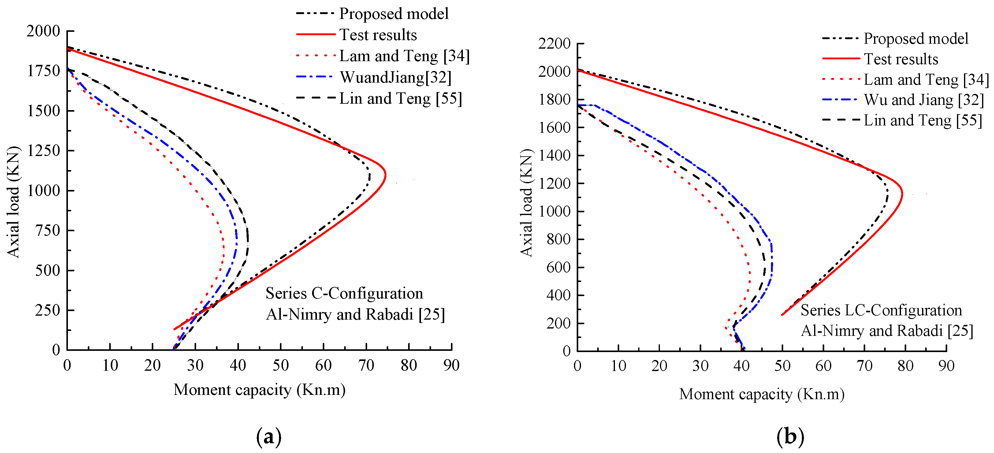
5.2. Performance of Proposed and Existing P–M Models
6. Conclusions and Future Research
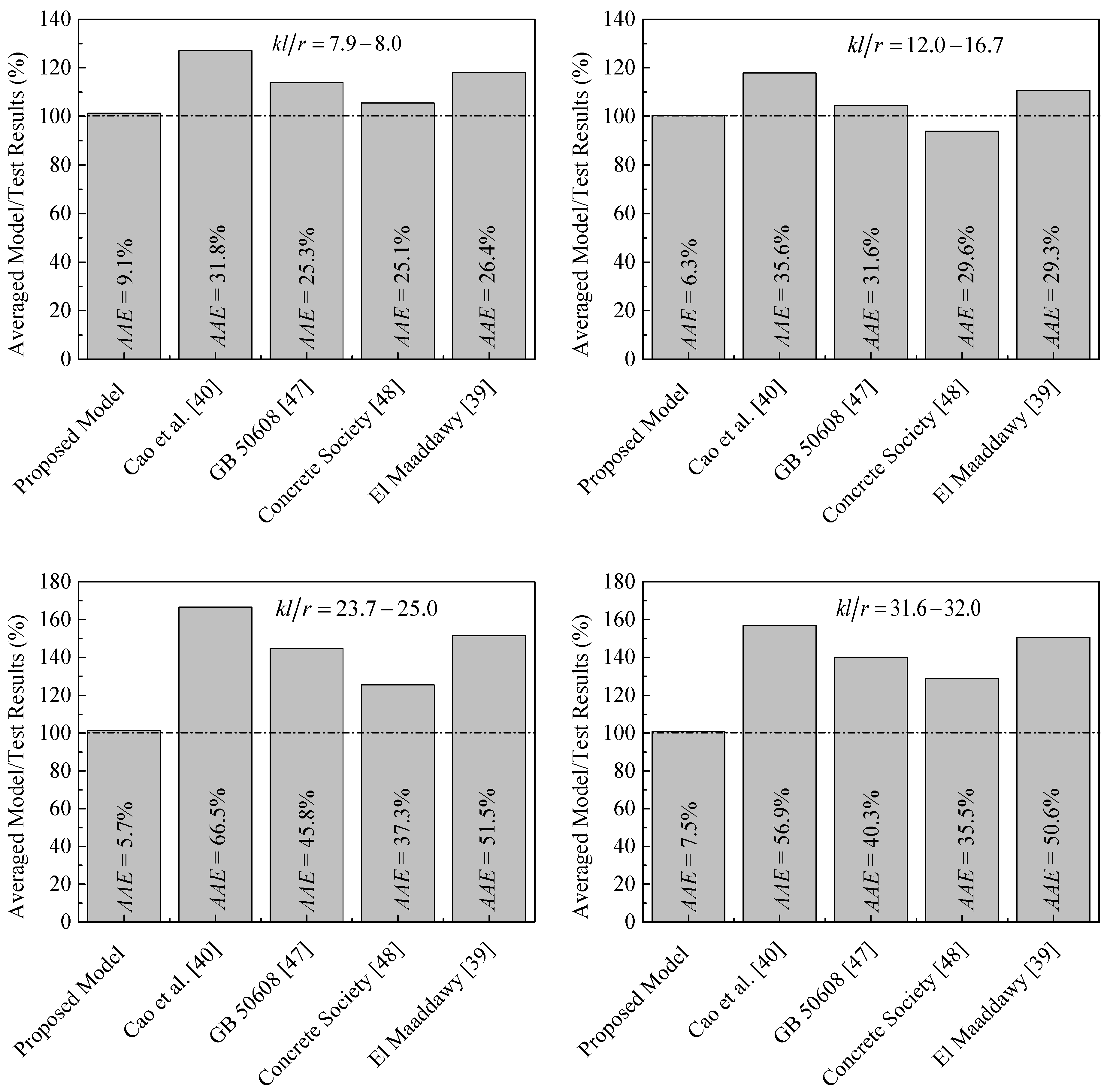
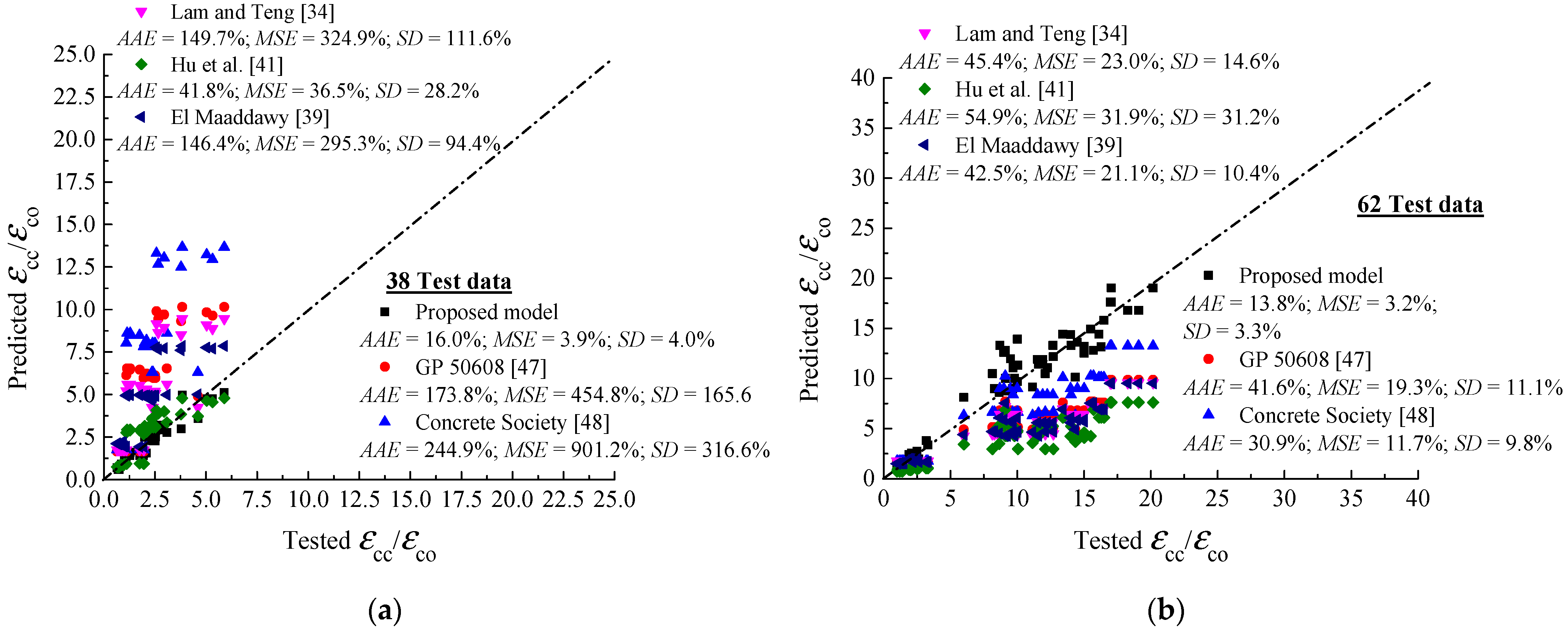
- None of the existing design codes and models, among them the GB 50608 [47] and Concrete Society [48], provide accurate predictions for the peak strength and strain, and due to the large test data and parameters studied in the present paper, this finding contradicts a recent conclusion made by Xing et al. [76].
- A design-oriented stress–strain model was newly developed using a database of 207 FRP-confined plain and RC columns under different loading conditions. The model parameters included longitudinal and hoop steel reinforcement ratio, amount of FRP hoop wraps, presence of longitudinal FRP sheets, slenderness ratio, eccentric loading ratio, column section’s size, and compressive strength of unconfined concrete.
- Based on a parametric investigation by the model, the sufficiently confined concrete threshold under eccentric loads was proposed to be 0.22, which is larger than that of Pham and Hadi. [66], since the test database employed in their study mostly contains results of small-scale circular specimens under concentric loading.
- For slender columns, significantly underestimated predictions of the P–M responses were obtained using both the existing concentric and eccentric stress–strain models of FRP-confined concrete cylinders. However, good agreement between the proposed predictions and tested responses was found, confirming that the model can simulate slender RC columns experiencing greater flexural resistance when strengthened with lateral and longitudinal FRP sheets.
Author Contributions
Funding
Institutional Review Board Statement
Informed Consent Statement
Data Availability Statement
Acknowledgments
Conflicts of Interest
Appendix A

| Specimens | Concrete | Internal Steel Reinforcement | Fiber-Reinforced Polymer | Key Results | ||||||||||||
|---|---|---|---|---|---|---|---|---|---|---|---|---|---|---|---|---|
| No. | Specimen | D (mm) | l (mm) | e (mm) | fc’ (MPa) | Hoop reo. | Vertical reo. | fyl (MPa) | fyh (MPa) | nf | nf,v | tf (mm) | ff (MPa) | Ef (GPa) | εfu (%) | Nu (KN) |
| Al-Nimry and Rahadi [25] | ||||||||||||||||
| 1 | G0-U-A | 192 | 1200 | 0 | 58.95 | Ø6@96 mm | 6Φ10 mm | 418 | 524 | 0 | 0 | 0.166 | 4900 | 300 | 2.1 | 1529 |
| 2 | G0-U-B | 192 | 1200 | 0 | 58.95 | Ø6@96 mm | 6Φ10 mm | 418 | 524 | 0 | 0 | 0.166 | 4900 | 300 | 2.1 | 1573 |
| 3 | G0-C-A | 192 | 1200 | 0 | 58.95 | Ø6@96 mm | 6Φ10 mm | 418 | 524 | 1 | 0 | 0.166 | 4900 | 300 | 2.1 | 1930 |
| 4 | G0-C-B | 192 | 1200 | 0 | 58.95 | Ø6@96 mm | 6Φ10 mm | 418 | 524 | 1 | 0 | 0.166 | 4900 | 300 | 2.1 | 1872 |
| 5 | G0-LC-A | 192 | 1200 | 0 | 58.95 | Ø6@96 mm | 6Φ10 mm | 418 | 524 | 1 | 1 | 0.166 | 4900 | 300 | 2.1 | 1987 |
| 6 | G0-LC-B | 192 | 1200 | 0 | 58.95 | Ø6@96 mm | 6Φ10 mm | 418 | 524 | 1 | 1 | 0.166 | 4900 | 300 | 2.1 | 2041 |
| 7 | G0-LC-C | 192 | 1200 | 0 | 58.95 | Ø6@96 mm | 6Φ10 mm | 418 | 524 | 1 | 1 | 0.166 | 4900 | 300 | 2.1 | 2021 |
| 8 | G25-U-A | 192 | 1200 | 25 | 58.95 | Ø6@96 mm | 6Φ10 mm | 418 | 524 | 0 | 0 | 0.166 | 4900 | 300 | 2.1 | 1351 |
| 9 | G25-U-B | 192 | 1200 | 25 | 58.95 | Ø6@96 mm | 6Φ10 mm | 418 | 524 | 0 | 0 | 0.166 | 4900 | 300 | 2.1 | 1154 |
| 10 | G25-C-A | 192 | 1200 | 25 | 58.95 | Ø6@96 mm | 6Φ10 mm | 418 | 524 | 1 | 0 | 0.166 | 4900 | 300 | 2.1 | 1545 |
| 11 | G25-C-B | 192 | 1200 | 25 | 58.95 | Ø6@96 mm | 6Φ10 mm | 418 | 524 | 1 | 0 | 0.166 | 4900 | 300 | 2.1 | 1580 |
| 12 | G25-LC | 192 | 1200 | 25 | 58.95 | Ø6@96 mm | 6Φ10 mm | 418 | 524 | 1 | 1 | 0.166 | 4900 | 300 | 2.1 | 1682 |
| 13 | G50-U-A | 192 | 1200 | 50 | 58.95 | Ø6@96 mm | 6Φ10 mm | 418 | 524 | 0 | 0 | 0.166 | 4900 | 300 | 2.1 | 900 |
| 14 | G50-U-B | 192 | 1200 | 50 | 58.95 | Ø6@96 mm | 6Φ10 mm | 418 | 524 | 0 | 0 | 0.166 | 4900 | 300 | 2.1 | 894 |
| 15 | G50-C | 192 | 1200 | 50 | 58.95 | Ø6@96 mm | 6Φ10 mm | 418 | 524 | 1 | 0 | 0.166 | 4900 | 300 | 2.1 | 1210 |
| 16 | G50-LC-A | 192 | 1200 | 50 | 58.95 | Ø6@96 mm | 6Φ10 mm | 418 | 524 | 1 | 1 | 0.166 | 4900 | 300 | 2.1 | 1341 |
| 17 | G50-LC-B | 192 | 1200 | 50 | 58.95 | Ø6@96 mm | 6Φ10 mm | 418 | 524 | 1 | 1 | 0.166 | 4900 | 300 | 2.1 | 1303 |
| 18 | G65-U | 192 | 1200 | 65 | 58.95 | Ø6@96 mm | 6Φ10 mm | 418 | 524 | 0 | 0 | 0.166 | 4900 | 300 | 2.1 | 789 |
| 19 | G65-C | 192 | 1200 | 65 | 58.95 | Ø6@96 mm | 6Φ10 mm | 418 | 524 | 1 | 0 | 0.166 | 4900 | 300 | 2.1 | 1048 |
| 20 | G65-LC | 192 | 1200 | 65 | 58.95 | Ø6@96 mm | 6Φ10 mm | 418 | 524 | 1 | 1 | 0.166 | 4900 | 300 | 2.1 | 1122 |
| Al-Nimry and Soman [26] | ||||||||||||||||
| 21 | C1-S1-A | 192 | 1175 | 50 | 41.1 | Ø6@125 mm | 6Φ10 mm | 451 | 528 | 0 | 0 | 0.166 | 4900 | 300 | 2.1 | 831 |
| 22 | C1-S1-B | 192 | 1175 | 50 | 41.1 | Ø6@125 mm | 6Φ10 mm | 451 | 528 | 0 | 0 | 0.166 | 4900 | 300 | 2.1 | 806 |
| 23 | C1-S1-1C-A | 192 | 1175 | 50 | 41.9 | Ø6@125 mm | 6Φ10 mm | 451 | 528 | 1 | 0 | 0.166 | 4900 | 300 | 2.1 | 1031 |
| 24 | C1-S1-1C-B | 192 | 1175 | 50 | 41.9 | Ø6@125 mm | 6Φ10 mm | 451 | 528 | 1 | 0 | 0.166 | 4900 | 300 | 2.1 | 1043 |
| 25 | C1-S1-1V1C-A | 192 | 1175 | 50 | 44.4 | Ø6@125 mm | 6Φ10 mm | 451 | 528 | 1 | 1 | 0.166 | 4900 | 300 | 2.1 | 1011 |
| 26 | C1-S1-1V1C-B | 192 | 1175 | 50 | 47.8 | Ø6@125 mm | 6Φ10 mm | 451 | 528 | 1 | 1 | 0.166 | 4900 | 300 | 2.1 | 1122 |
| 27 | C1-S1-1V-2C-A | 192 | 1175 | 50 | 44 | Ø6@125 mm | 6Φ10 mm | 451 | 528 | 2 | 1 | 0.166 | 4900 | 300 | 2.1 | 1263 |
| 28 | C1-S1-1V-2C-B | 192 | 1175 | 50 | 46.8 | Ø6@125 mm | 6Φ10 mm | 451 | 528 | 2 | 1 | 0.166 | 4900 | 300 | 2.1 | 1273 |
| 29 | C1-S2-A | 192 | 1175 | 50 | 39.5 | Ø6@187.5 mm | 6Φ10 mm | 451 | 528 | 0 | 0 | 0.166 | 4900 | 300 | 2.1 | 824 |
| 30 | C1-S2-B | 192 | 1175 | 50 | 39.5 | Ø6@187.5 mm | 6Φ10 mm | 451 | 528 | 0 | 0 | 0.166 | 4900 | 300 | 2.1 | 777 |
| 31 | C1-S2-1C-A | 192 | 1175 | 50 | 45.7 | Ø6@187.5 mm | 6Φ10 mm | 451 | 528 | 1 | 0 | 0.166 | 4900 | 300 | 2.1 | 941 |
| 32 | C1-S2-1C-B | 192 | 1175 | 50 | 45.7 | Ø6@187.5 mm | 6Φ10 mm | 451 | 528 | 1 | 0 | 0.166 | 4900 | 300 | 2.1 | 970 |
| 33 | C1-S2-1V1C-A | 192 | 1175 | 50 | 41 | Ø6@187.5 mm | 6Φ10 mm | 451 | 528 | 1 | 1 | 0.166 | 4900 | 300 | 2.1 | 972 |
| 34 | C1-S2-1V1C-B | 192 | 1175 | 50 | 41 | Ø6@187.5 mm | 6Φ10 mm | 451 | 528 | 1 | 1 | 0.166 | 4900 | 300 | 2.1 | 946 |
| 35 | C1-S2-1V-2C-A | 192 | 1175 | 50 | 42.7 | Ø6@187.5 mm | 6Φ10 mm | 451 | 528 | 2 | 1 | 0.166 | 4900 | 300 | 2.1 | 1290 |
| 36 | C1-S2-1V-2C-B | 192 | 1175 | 50 | 45.9 | Ø6@187.5 mm | 6Φ10 mm | 451 | 528 | 2 | 1 | 0.166 | 4900 | 300 | 2.1 | 1302 |
| 37 | C2-S1-A | 192 | 800 | 50 | 44 | Ø6@125 mm | 6Φ10 mm | 451 | 528 | 0 | 0 | 0.166 | 4900 | 300 | 2.1 | 879 |
| 38 | C2-S1-B | 192 | 800 | 50 | 44 | Ø6@125 mm | 6Φ10 mm | 451 | 528 | 0 | 0 | 0.166 | 4900 | 300 | 2.1 | 867 |
| 39 | C2-S1-1C-A | 192 | 800 | 50 | 46.8 | Ø6@125 mm | 6Φ10 mm | 451 | 528 | 1 | 0 | 0.166 | 4900 | 300 | 2.1 | 1205 |
| 40 | C2-S1-1C-B | 192 | 800 | 50 | 46.8 | Ø6@125 mm | 6Φ10 mm | 451 | 528 | 1 | 0 | 0.166 | 4900 | 300 | 2.1 | 1309 |
| 41 | C2-S1-1V1C-A | 192 | 800 | 50 | 47.8 | Ø6@125 mm | 6Φ10 mm | 451 | 528 | 1 | 1 | 0.166 | 4900 | 300 | 2.1 | 1298 |
| Al-Nimry and Soman [26] | ||||||||||||||||
| 42 | C2-S1-1V1C-B | 192 | 800 | 50 | 47.8 | Ø6@125 mm | 6Φ10 mm | 451 | 528 | 1 | 1 | 0.166 | 4900 | 300 | 2.1 | 1254 |
| 43 | C2-S1-1V-2C-A | 192 | 800 | 50 | 44.4 | Ø6@125 mm | 6Φ10 mm | 451 | 528 | 2 | 1 | 0.166 | 4900 | 300 | 2.1 | 1608 |
| 44 | C2-S1-1V-2C-B | 192 | 800 | 50 | 41.1 | Ø6@125 mm | 6Φ10 mm | 451 | 528 | 2 | 1 | 0.166 | 4900 | 300 | 2.1 | 1501 |
| 45 | C2-S2-A | 192 | 800 | 50 | 42.7 | Ø6@187.5 mm | 6Φ10 mm | 451 | 528 | 0 | 0 | 0.166 | 4900 | 300 | 2.1 | 815 |
| 46 | C2-S2-B | 192 | 800 | 50 | 42.7 | Ø6@187.5 mm | 6Φ10 mm | 451 | 528 | 0 | 0 | 0.166 | 4900 | 300 | 2.1 | 863 |
| 47 | C2-S2-1C-A | 192 | 800 | 50 | 45.9 | Ø6@187.5 mm | 6Φ10 mm | 451 | 528 | 1 | 0 | 0.166 | 4900 | 300 | 2.1 | 1210 |
| 48 | C2-S2-1C-B | 192 | 800 | 50 | 45.9 | Ø6@187.5 mm | 6Φ10 mm | 451 | 528 | 1 | 0 | 0.166 | 4900 | 300 | 2.1 | 1147 |
| 49 | C2-S2-1V1C-A | 192 | 800 | 50 | 45.7 | Ø6@187.5 mm | 6Φ10 mm | 451 | 528 | 1 | 1 | 0.166 | 4900 | 300 | 2.1 | 1214 |
| 50 | C2-S2-1V1C-B | 192 | 800 | 50 | 41 | Ø6@187.5 mm | 6Φ10 mm | 451 | 528 | 1 | 1 | 0.166 | 4900 | 300 | 2.1 | 1189 |
| 51 | C2-S2-1V-2C-A | 192 | 800 | 50 | 43.1 | Ø6@187.5 mm | 6Φ10 mm | 451 | 528 | 2 | 1 | 0.166 | 4900 | 300 | 2.1 | 1555 |
| 52 | C2-S2-1V-2C-B | 192 | 800 | 50 | 41.1 | Ø6@187.5 mm | 6Φ10 mm | 451 | 528 | 2 | 1 | 0.166 | 4900 | 300 | 2.1 | 1405 |
| Bisby and Ranger [27] | ||||||||||||||||
| 53 | U-0 | 152 | 608 | 0 | 33.2 | Ø6.4@100 mm | 4Φ6.4 mm | 710 | 710 | 0 | 0 | 0.12 | 4100 | 234 | 1.7 | 497 |
| 54 | C-0 | 152 | 608 | 0 | 33.2 | Ø6.4@100 mm | 4Φ6.4 mm | 710 | 710 | 1 | 0 | 0.12 | 4100 | 234 | 1.7 | 873 |
| 55 | U-5 | 152 | 608 | 5 | 33.2 | Ø6.4@100 mm | 4Φ6.4 mm | 710 | 710 | 0 | 0 | 0.12 | 4100 | 234 | 1.7 | 459 |
| 56 | C-5 | 152 | 608 | 5 | 33.2 | Ø6.4@100 mm | 4Φ6.4 mm | 710 | 710 | 1 | 0 | 0.12 | 4100 | 234 | 1.7 | 770 |
| 57 | U-10 | 152 | 608 | 10 | 33.2 | Ø6.4@100 mm | 4Φ6.4 mm | 710 | 710 | 0 | 0 | 0.12 | 4100 | 234 | 1.7 | 447 |
| 58 | C-10 | 152 | 608 | 10 | 33.2 | Ø6.4@100 mm | 4Φ6.4 mm | 710 | 710 | 1 | 0 | 0.12 | 4100 | 234 | 1.7 | 664 |
| 59 | U-20 | 152 | 608 | 20 | 33.2 | Ø6.4@100 mm | 4Φ6.4 mm | 710 | 710 | 0 | 0 | 0.12 | 4100 | 234 | 1.7 | 351 |
| 60 | C-20 | 152 | 608 | 20 | 33.2 | Ø6.4@100 mm | 4Φ6.4 mm | 710 | 710 | 1 | 0 | 0.12 | 4100 | 234 | 1.7 | 579 |
| Fitzwilliam and Bisby [28] | ||||||||||||||||
| 61 | 300U-A | 152 | 300 | 20 | 30.5 | Ø6.4@100 mm | 4Φ6.4 mm | 693 | 693 | 0 | 0 | 0.12 | 4100 | 234 | 1.7 | 467 |
| 62 | 300U-B | 152 | 300 | 20 | 30.5 | Ø6.4@100 mm | 4Φ6.4 mm | 693 | 693 | 0 | 0 | 0.12 | 4100 | 234 | 1.7 | 460 |
| 63 | 300C-1-0-A | 152 | 300 | 20 | 30.5 | Ø6.4@100 mm | 4Φ6.4 mm | 693 | 693 | 1 | 0 | 0.12 | 4100 | 234 | 1.7 | 672 |
| 64 | 300C-1-0-B | 152 | 300 | 20 | 30.5 | Ø6.4@100 mm | 4Φ6.4 mm | 693 | 693 | 1 | 0 | 0.12 | 4100 | 234 | 1.7 | 683 |
| 65 | 300C-1-2-A | 152 | 300 | 20 | 30.5 | Ø6.4@100 mm | 4Φ6.4 mm | 693 | 693 | 1 | 2 | 0.12 | 4100 | 234 | 1.7 | 681 |
| 66 | 300C-2-0-A | 152 | 300 | 20 | 30.5 | Ø6.4@100 mm | 4Φ6.4 mm | 693 | 693 | 2 | 0 | 0.12 | 4100 | 234 | 1.7 | 670 |
| 67 | 300C-2-0-B | 152 | 300 | 20 | 30.5 | Ø6.4@100 mm | 4Φ6.4 mm | 693 | 693 | 2 | 0 | 0.12 | 4100 | 234 | 1.7 | 911 |
| 68 | 600U-A | 152 | 600 | 20 | 30.5 | Ø6.4@100 mm | 4Φ6.4 mm | 693 | 693 | 0 | 0 | 0.12 | 4100 | 234 | 1.7 | 426 |
| 69 | 600C-1-0-A | 152 | 600 | 20 | 30.5 | Ø6.4@100 mm | 4Φ6.4 mm | 693 | 693 | 1 | 0 | 0.12 | 4100 | 234 | 1.7 | 561 |
| 70 | 900U-A | 152 | 900 | 20 | 30.5 | Ø6.4@100 mm | 4Φ6.4 mm | 693 | 693 | 0 | 0 | 0.12 | 4100 | 234 | 1.7 | 397 |
| 71 | 900C-1-0-A | 152 | 900 | 20 | 30.5 | Ø6.4@100 mm | 4Φ6.4 mm | 693 | 693 | 1 | 0 | 0.12 | 4100 | 234 | 1.7 | 549 |
| 72 | 1200U-A | 152 | 1200 | 20 | 30.5 | Ø6.4@100 mm | 4Φ6.4 mm | 693 | 693 | 0 | 0 | 0.12 | 4100 | 234 | 1.7 | 388 |
| 73 | 1200U-B | 152 | 1200 | 20 | 30.5 | Ø6.4@100 mm | 4Φ6.4 mm | 693 | 693 | 0 | 0 | 0.12 | 4100 | 234 | 1.7 | 411 |
| 74 | 1200C-1-0-A | 152 | 1200 | 20 | 30.5 | Ø6.4@100 mm | 4Φ6.4 mm | 693 | 693 | 1 | 0 | 0.12 | 4100 | 234 | 1.7 | 449 |
| 75 | 1200C-1-0-B | 152 | 1200 | 20 | 30.5 | Ø6.4@100 mm | 4Φ6.4 mm | 693 | 693 | 1 | 0 | 0.12 | 4100 | 234 | 1.7 | 480 |
| 76 | 1200C-1-2-A | 152 | 1200 | 20 | 30.5 | Ø6.4@100 mm | 4Φ6.4 mm | 693 | 693 | 1 | 2 | 0.12 | 4100 | 234 | 1.7 | 582 |
| 77 | 1200C-1-4-A | 152 | 1200 | 20 | 30.5 | Ø6.4@100 mm | 4Φ6.4 mm | 693 | 693 | 1 | 4 | 0.12 | 4100 | 234 | 1.7 | 671 |
| 78 | 1200C-2-0-A | 152 | 1200 | 20 | 30.5 | Ø6.4@100 mm | 4Φ6.4 mm | 693 | 693 | 2 | 0 | 0.12 | 4100 | 234 | 1.7 | 537 |
| Jiang et al. [29] | ||||||||||||||||
| 79 | L1E0A | 150 | 300 | 0 | 38.1 | - | - | - | - | 1 | 0 | 0.11 | 4743.6 | 268 | 1.77 | 979.5 |
| 80 | L1E0B | 150 | 300 | 0 | 38.1 | - | - | - | - | 1 | 0 | 0.11 | 4743.6 | 268 | 1.77 | 950.9 |
| 81 | L1E10A | 150 | 300 | 10 | 38.1 | - | - | - | - | 1 | 0 | 0.11 | 4743.6 | 268 | 1.77 | 779.3 |
| 82 | L1E10B | 150 | 300 | 10 | 38.1 | - | - | - | - | 1 | 0 | 0.11 | 4743.6 | 268 | 1.77 | 744.8 |
| 83 | L1E20A | 150 | 300 | 20 | 38.1 | - | - | - | - | 1 | 0 | 0.11 | 4743.6 | 268 | 1.77 | 602.9 |
| 84 | L1E20B | 150 | 300 | 20 | 38.1 | - | - | - | - | 1 | 0 | 0.11 | 4743.6 | 268 | 1.77 | 610.2 |
| 85 | L1E30A | 150 | 300 | 30 | 38.1 | - | - | - | - | 1 | 0 | 0.11 | 4743.6 | 268 | 1.77 | 452.1 |
| 86 | L1E30B | 150 | 300 | 30 | 38.1 | - | - | - | - | 1 | 0 | 0.11 | 4743.6 | 268 | 1.77 | 464.6 |
| 87 | L2E0A | 150 | 300 | 0 | 39.4 | - | - | - | - | 2 | 0 | 0.11 | 4690.4 | 266.5 | 1.76 | 1306.3 |
| 88 | L2E0B | 150 | 300 | 0 | 39.4 | - | - | - | - | 2 | 0 | 0.11 | 4690.4 | 266.5 | 1.76 | 1359 |
| 89 | L2E10A | 150 | 300 | 10 | 39.4 | - | - | - | - | 2 | 0 | 0.11 | 4690.4 | 266.5 | 1.76 | 1099.6 |
| 90 | L2E10B | 150 | 300 | 10 | 39.4 | - | - | - | - | 2 | 0 | 0.11 | 4690.4 | 266.5 | 1.76 | 1084.6 |
| 91 | L2E20A | 150 | 300 | 20 | 39.4 | - | - | - | - | 2 | 0 | 0.11 | 4690.4 | 266.5 | 1.76 | 899.6 |
| 92 | L2E20B | 150 | 300 | 20 | 39.4 | - | - | - | - | 2 | 0 | 0.11 | 4690.4 | 266.5 | 1.76 | 904.4 |
| 93 | L2E30A | 150 | 300 | 30 | 39.4 | - | - | - | - | 2 | 0 | 0.11 | 4690.4 | 266.5 | 1.76 | 668 |
| 94 | L2E30B | 150 | 300 | 30 | 39.4 | - | - | - | - | 2 | 0 | 0.11 | 4690.4 | 266.5 | 1.76 | 648.6 |
| Siddiqui et al. [30] | ||||||||||||||||
| 95 | STR1-600 | 150 | 600 | 25 | 35.1 | Ø6@100 mm | 4Φ8 mm | 420 | 275 | 1 | 0 | 1 | 846 | 77.3 | 1.1 | 541.3 |
| 96 | STR2-600 | 150 | 600 | 25 | 35.1 | Ø6@100 mm | 4Φ8 mm | 420 | 275 | 1 | 2 | 1 | 846 | 77.3 | 1.1 | 745.2 |
| 97 | STR3-600 | 150 | 600 | 25 | 35.1 | Ø6@100 mm | 4Φ8 mm | 420 | 275 | 1 | 4 | 1 | 846 | 77.3 | 1.1 | 829.9 |
| 98 | STR2-900 | 150 | 900 | 25 | 35.1 | Ø6@100 mm | 4Φ8 mm | 420 | 275 | 1 | 2 | 1 | 846 | 77.3 | 1.1 | 580.9 |
| 99 | STR3-900 | 150 | 900 | 25 | 35.1 | Ø6@100 mm | 4Φ8 mm | 420 | 275 | 1 | 4 | 1 | 846 | 77.3 | 1.1 | 660.9 |
| 100 | STR2-1200 | 150 | 1200 | 25 | 35.1 | Ø6@100 mm | 4Φ8 mm | 420 | 275 | 1 | 2 | 1 | 846 | 77.3 | 1.1 | 545.2 |
| 101 | STR3-1200 | 150 | 1200 | 25 | 35.1 | Ø6@100 mm | 4Φ8 mm | 420 | 275 | 1 | 4 | 1 | 846 | 77.3 | 1.1 | 647.1 |
| Wang et al. [31] | ||||||||||||||||
| 102 | P-E0-1 | 150 | 300 | 0 | 37.7 | - | - | - | - | 0 | 0 | 0.167 | 3400 | 240 | 1.6 | 664 |
| 103 | P-E0-2 | 150 | 300 | 0 | 37.7 | - | - | - | - | 2 | 0 | 0.167 | 3400 | 240 | 1.6 | 1542 |
| 104 | F-E0-1 | 150 | 300 | 0 | 37.7 | - | - | - | - | 2 | 0 | 0.167 | 3400 | 240 | 1.6 | 1612 |
| 105 | F-E0-2 | 150 | 300 | 0 | 37.7 | - | - | - | - | 2 | 0 | 0.167 | 3400 | 240 | 1.6 | 1053 |
| 106 | F-E15-1 | 150 | 300 | 15 | 37.7 | - | - | - | - | 2 | 0 | 0.167 | 3400 | 240 | 1.6 | 1069 |
| 107 | F-E15-2 | 150 | 300 | 15 | 37.7 | - | - | - | - | 2 | 0 | 0.167 | 3400 | 240 | 1.6 | 802 |
| 108 | F-E25-1 | 150 | 300 | 25 | 37.7 | - | - | - | - | 2 | 0 | 0.167 | 3400 | 240 | 1.6 | 790 |
| 109 | F-E25-2 | 150 | 300 | 25 | 37.7 | - | - | - | - | 0 | 0 | 0.167 | 3400 | 240 | 1.6 | 664 |
| Wu and Jiang [32] | ||||||||||||||||
| 110 | A0E0 | 150 | 300 | 0 | 21.2 | - | - | - | - | 0 | 0 | 0.167 | 4192 | 254 | 1.84 | 370.8 |
| 111 | B0E0 | 150 | 300 | 0 | 21.2 | - | - | - | - | 0 | 0 | 0.167 | 4192 | 254 | 1.84 | 379.8 |
| 112 | A0E10 | 150 | 300 | 10 | 21.2 | - | - | - | - | 0 | 0 | 0.167 | 4192 | 254 | 1.84 | 337.8 |
| 113 | B0E10 | 150 | 300 | 10 | 21.2 | - | - | - | - | 0 | 0 | 0.167 | 4192 | 254 | 1.84 | 330.9 |
| 114 | A0E20 | 150 | 300 | 20 | 21.2 | - | - | - | - | 0 | 0 | 0.167 | 4192 | 254 | 1.84 | 300.9 |
| 115 | B0E20 | 150 | 300 | 20 | 21.2 | - | - | - | - | 0 | 0 | 0.167 | 4192 | 254 | 1.84 | 291.9 |
| 116 | A0E30 | 150 | 300 | 30 | 21.2 | - | - | - | - | 0 | 0 | 0.167 | 4192 | 254 | 1.84 | 288.9 |
| 117 | B0E30 | 150 | 300 | 30 | 21.2 | - | - | - | - | 0 | 0 | 0.167 | 4192 | 254 | 1.84 | 271.9 |
| Wu and Jiang [32] | ||||||||||||||||
| 118 | A0E40 | 150 | 300 | 40 | 21.2 | - | - | - | - | 0 | 0 | 0.167 | 4192 | 254 | 1.84 | 248.9 |
| 119 | B0E40 | 150 | 300 | 40 | 21.2 | - | - | - | - | 0 | 0 | 0.167 | 4192 | 254 | 1.84 | 238.9 |
| 120 | A0E50 | 150 | 300 | 50 | 21.2 | - | - | - | - | 0 | 0 | 0.167 | 4192 | 254 | 1.84 | 202.9 |
| 121 | B0E50 | 150 | 300 | 50 | 21.2 | - | - | - | - | 0 | 0 | 0.167 | 4192 | 254 | 1.84 | 185.9 |
| 122 | A1E0 | 150 | 300 | 0 | 28.7 | - | - | - | - | 1 | 0 | 0.167 | 4192 | 254 | 1.84 | 1048.6 |
| 123 | B1E0 | 150 | 300 | 0 | 28.7 | - | - | - | - | 1 | 0 | 0.167 | 4192 | 254 | 1.84 | 968.7 |
| 124 | A1E10 | 150 | 300 | 10 | 28.7 | - | - | - | - | 1 | 0 | 0.167 | 4192 | 254 | 1.84 | 938.7 |
| 125 | B1E10 | 150 | 300 | 10 | 28.7 | - | - | - | - | 1 | 0 | 0.167 | 4192 | 254 | 1.84 | 880.7 |
| 126 | A1E20 | 150 | 300 | 20 | 28.7 | - | - | - | - | 1 | 0 | 0.167 | 4192 | 254 | 1.84 | 850.7 |
| 127 | B1E20 | 150 | 300 | 20 | 28.7 | - | - | - | - | 1 | 0 | 0.167 | 4192 | 254 | 1.84 | 739.7 |
| 128 | A1E30 | 150 | 300 | 30 | 28.7 | - | - | - | - | 1 | 0 | 0.167 | 4192 | 254 | 1.84 | 755.7 |
| 129 | B1E30 | 150 | 300 | 30 | 28.7 | - | - | - | - | 1 | 0 | 0.167 | 4192 | 254 | 1.84 | 768.7 |
| 130 | A1E40 | 150 | 300 | 40 | 28.7 | - | - | - | - | 1 | 0 | 0.167 | 4192 | 254 | 1.84 | 691.7 |
| 131 | B1E40 | 150 | 300 | 40 | 28.7 | - | - | - | - | 1 | 0 | 0.167 | 4192 | 254 | 1.84 | 633.8 |
| 132 | A1E50 | 150 | 300 | 50 | 28.7 | - | - | - | - | 1 | 0 | 0.167 | 4192 | 254 | 1.84 | 474.8 |
| 133 | B1E50 | 150 | 300 | 50 | 28.7 | - | - | - | - | 1 | 0 | 0.167 | 4192 | 254 | 1.84 | 434.8 |
| 134 | A2E0 | 150 | 300 | 0 | 30.1 | - | - | - | - | 2 | 0 | 0.167 | 4192 | 254 | 1.84 | 1557.5 |
| Wu and Jiang [32] | ||||||||||||||||
| 135 | B2E0 | 150 | 300 | 0 | 30.1 | - | - | - | - | 2 | 0 | 0.167 | 4192 | 254 | 1.84 | 1597.5 |
| 136 | A2E10 | 150 | 300 | 10 | 30.1 | - | - | - | - | 2 | 0 | 0.167 | 4192 | 254 | 1.84 | 1463.5 |
| 137 | B2E10 | 150 | 300 | 10 | 30.1 | - | - | - | - | 2 | 0 | 0.167 | 4192 | 254 | 1.84 | 1434.5 |
| 138 | A2E20 | 150 | 300 | 20 | 30.1 | - | - | - | - | 2 | 0 | 0.167 | 4192 | 254 | 1.84 | 1267.6 |
| 139 | B2E20 | 150 | 300 | 20 | 30.1 | - | - | - | - | 2 | 0 | 0.167 | 4192 | 254 | 1.84 | 1349.5 |
| 140 | A2E30 | 150 | 300 | 30 | 30.1 | - | - | - | - | 2 | 0 | 0.167 | 4192 | 254 | 1.84 | 1164.6 |
| 141 | B2E30 | 150 | 300 | 30 | 30.1 | - | - | - | - | 2 | 0 | 0.167 | 4192 | 254 | 1.84 | 1201.6 |
| 142 | A2E40 | 150 | 300 | 40 | 30.1 | - | - | - | - | 2 | 0 | 0.167 | 4192 | 254 | 1.84 | 908.7 |
| 143 | B2E40 | 150 | 300 | 40 | 30.1 | - | - | - | - | 2 | 0 | 0.167 | 4192 | 254 | 1.84 | 862.7 |
| 144 | A2E50 | 150 | 300 | 50 | 30.1 | - | - | - | - | 2 | 0 | 0.167 | 4192 | 254 | 1.84 | 704.7 |
| 145 | B2E50 | 150 | 300 | 50 | 30.1 | - | - | - | - | 2 | 0 | 0.167 | 4192 | 254 | 1.84 | 678.7 |
| Wang et al. [23] | ||||||||||||||||
| 146 | C1H1L0M | 305 | 915 | 0 | 24.5 | Ø6@80 mm | 8Φ12 mm | 340 | 397 | 0 | - | 0.167 | 4340 | 244 | 1.78 | 41.5 |
| 147 | C1H2L0M | 305 | 915 | 0 | 24.5 | Ø6@40 mm | 8Φ12 mm | 340 | 397 | 0 | - | 0.167 | 4340 | 244 | 1.78 | 62.1 |
| 148 | C1H1L1M | 305 | 915 | 0 | 24.5 | Ø6@80 mm | 8Φ12 mm | 340 | 397 | 1 | - | 0.167 | 4340 | 244 | 1.78 | 41.5 |
| 149 | C1H1L1C | 305 | 915 | 0 | 24.5 | Ø6@80 mm | 8Φ12 mm | 340 | 397 | 1 | - | 0.167 | 4340 | 244 | 1.78 | 43.1 |
| 150 | C1H0L1M | 305 | 915 | 0 | 24.5 | - | - | - | 397 | 1 | - | 0.167 | 4340 | 244 | 1.78 | 35.0 |
| 151 | C1H0L2M | 305 | 915 | 0 | 24.5 | - | - | - | 397 | 2 | - | 0.167 | 4340 | 244 | 1.78 | 55.3 |
| 152 | C1H1L2M | 305 | 915 | 0 | 24.5 | Ø6@80 mm | 8Φ12 mm | 340 | 397 | 2 | - | 0.167 | 4340 | 244 | 1.78 | 52.2 |
| 153 | C1H1L2C | 305 | 915 | 0 | 24.5 | Ø6@80 mm | 8Φ12 mm | 340 | 397 | 2 | - | 0.167 | 4340 | 244 | 1.78 | 61.8 |
| 154 | C1H2L1M | 305 | 915 | 0 | 24.5 | Ø6@40 mm | 8Φ12 mm | 340 | 397 | 1 | - | 0.167 | 4340 | 244 | 1.78 | 47.0 |
| 155 | C1H2L2M | 305 | 915 | 0 | 24.5 | Ø6@40 mm | 8Φ12 mm | 340 | 397 | 2 | - | 0.167 | 4340 | 244 | 1.78 | 62.1 |
| 156 | C2H1L0M | 204 | 612 | 0 | 24.5 | Ø6@120 mm | 6Φ10 mm | 312 | 397 | 0 | - | 0.167 | 4340 | 244 | 1.78 | 52.1 |
| 157 | C2H2L0M | 204 | 612 | 0 | 24.5 | Ø6@60 mm | 6Φ10 mm | 312 | 397 | 0 | - | 0.167 | 4340 | 244 | 1.78 | 52.2 |
| 158 | C2H1L1M | 204 | 612 | 0 | 24.5 | Ø6@120 mm | 6Φ10 mm | 312 | 397 | 1 | - | 0.167 | 4340 | 244 | 1.78 | 52.1 |
| 159 | C2H1L1C | 204 | 612 | 0 | 24.5 | Ø6@120 mm | 6Φ10 mm | 312 | 397 | 1 | - | 0.167 | 4340 | 244 | 1.78 | 49.9 |
| 160 | C2H1L2M | 204 | 612 | 0 | 24.5 | Ø6@120 mm | 6Φ10 mm | 312 | 397 | 2 | - | 0.167 | 4340 | 244 | 1.78 | 66.1 |
| 161 | C2H1L2C | 204 | 612 | 0 | 24.5 | Ø6@120 mm | 6Φ10 mm | 312 | 397 | 2 | - | 0.167 | 4340 | 244 | 1.78 | 68.9 |
| 162 | C2H0L1M | 204 | 612 | 0 | 24.5 | - | - | - | 397 | 1 | - | 0.167 | 4340 | 244 | 1.78 | 46.1 |
| 163 | C2H0L1C | 204 | 612 | 0 | 24.5 | - | - | - | 397 | 1 | - | 0.167 | 4340 | 244 | 1.78 | 42.3 |
| 164 | C2H0L2M | 204 | 612 | 0 | 24.5 | - | - | - | 397 | 2 | - | 0.167 | 4340 | 244 | 1.78 | 65.2 |
| 165 | C2H0L2C | 204 | 612 | 0 | 24.5 | - | - | - | 397 | 2 | - | 0.167 | 4340 | 244 | 1.78 | 66.8 |
| 166 | C2H2L1M | 204 | 612 | 0 | 24.5 | Ø6@60 mm | 6Φ10 mm | 312 | 397 | 1 | - | 0.167 | 4340 | 244 | 1.78 | 52.2 |
| 167 | C2H2L1C | 204 | 612 | 0 | 24.5 | Ø6@60 mm | 6Φ10 mm | 312 | 397 | 1 | - | 0.167 | 4340 | 244 | 1.78 | 57.0 |
| 168 | C2H2L2M | 204 | 612 | 0 | 24.5 | Ø6@60 mm | 6Φ10 mm | 312 | 397 | 2 | - | 0.167 | 4340 | 244 | 1.78 | 69.5 |
| 169 | C2H2L2C | 204 | 612 | 0 | 24.5 | Ø6@60 mm | 6Φ10 mm | 312 | 397 | 2 | - | 0.167 | 4340 | 244 | 1.78 | 75.0 |
| Kaeseberg et al. [57] | ||||||||||||||||
| 170 | D15-TR-M1-2L-1 | 150 | 300 | 0 | 42.3 | Ø6@100 mm | 6Φ8 mm | 550 | 550 | 2 | 0 | 0.111 | 3900 | 230 | 1.70 | 83.8 |
| 171 | D15-TR-M1-2L-1 | 150 | 300 | 0 | 42.3 | Ø6@100 mm | 6Φ8 mm | 550 | 550 | 2 | 0 | 0.111 | 3900 | 230 | 1.70 | 89.5 |
| 172 | D15-TR-M1-2L-1 | 150 | 300 | 0 | 42.3 | Ø6@100 mm | 6Φ8 mm | 550 | 550 | 2 | 0 | 0.111 | 3900 | 230 | 1.70 | 86.2 |
| 173 | D15-TR-M1-2L-2 | 150 | 300 | 0 | 42.3 | Ø6@50 mm | 6Φ8 mm | 550 | 550 | 2 | 0 | 0.111 | 3900 | 230 | 1.70 | 83.3 |
| 174 | D15-TR-M1-2L-2 | 150 | 300 | 0 | 42.3 | Ø6@50 mm | 6Φ8 mm | 550 | 550 | 2 | 0 | 0.111 | 3900 | 230 | 1.70 | 81.9 |
| 175 | D15-TR-M1-2L-2 | 150 | 300 | 0 | 42.3 | Ø6@50 mm | 6Φ8 mm | 550 | 550 | 2 | 0 | 0.111 | 3900 | 230 | 1.70 | 73.0 |
| 176 | D20-TR-M1-2L-1 | 200 | 400 | 0 | 27.0 | Ø4@175 mm | 6Φ12 mm | 500 | 550 | 2 | 0 | 0.111 | 3900 | 230 | 1.70 | 65.1 |
| 177 | D20-TR-M1-2L-1 | 200 | 400 | 0 | 27.0 | Ø4@175 mm | 6Φ12 mm | 500 | 550 | 2 | 0 | 0.111 | 3900 | 230 | 1.70 | 69.4 |
| 178 | D20-TR-M1-2L-1 | 200 | 400 | 0 | 27.0 | Ø4@175 mm | 6Φ12 mm | 500 | 550 | 2 | 0 | 0.111 | 3900 | 230 | 1.70 | 67.8 |
| 179 | D20-TR-M1-2L-2 | 200 | 400 | 0 | 27.0 | Ø6@175 mm | 6Φ12 mm | 500 | 550 | 2 | 0 | 0.111 | 3900 | 230 | 1.70 | 65.0 |
| 180 | D20-TR-M1-2L-2 | 200 | 400 | 0 | 27.0 | Ø6@175 mm | 6Φ12 mm | 500 | 550 | 2 | 0 | 0.111 | 3900 | 230 | 1.70 | 64.4 |
| 181 | D20-TR-M1-2L-2 | 200 | 400 | 0 | 27.0 | Ø6@175 mm | 6Φ12 mm | 500 | 550 | 2 | 0 | 0.111 | 3900 | 230 | 1.70 | 60.8 |
| 182 | D20-TR-M2-2L-3a | 200 | 400 | 0 | 28.0 | Ø6@100 mm | 4Φ12 mm | 500 | 550 | 2 | 0 | 0.111 | 4100 | 230 | 1.78 | 66.1 |
| 183 | D20-TR-M2-2L-3a | 200 | 400 | 0 | 28.0 | Ø6@100 mm | 4Φ12 mm | 500 | 550 | 2 | 0 | 0.111 | 4100 | 230 | 1.78 | 68.7 |
| 184 | D20-TR-M2-2L-3a | 200 | 400 | 0 | 28.0 | Ø6@100 mm | 4Φ12 mm | 500 | 550 | 2 | 0 | 0.111 | 4100 | 230 | 1.78 | 67.1 |
| 185 | D20-TR-M2-2L-3b | 200 | 400 | 0 | 28.0 | Ø6@100 mm | 6Φ12 mm | 500 | 550 | 2 | 0 | 0.111 | 4100 | 230 | 1.78 | 72.8 |
| 186 | D20-TR-M2-2L-3b | 200 | 400 | 0 | 28.0 | Ø6@100 mm | 6Φ12 mm | 500 | 550 | 2 | 0 | 0.111 | 4100 | 230 | 1.78 | 75.9 |
| 187 | D20-TR-M2-2L-3b | 200 | 400 | 0 | 28.0 | Ø6@100 mm | 6Φ12 mm | 500 | 550 | 2 | 0 | 0.111 | 4100 | 230 | 1.78 | 72.8 |
| 188 | D20-TR-M2-2L-3c | 200 | 400 | 0 | 28.0 | Ø6@100 mm | 8Φ12 mm | 500 | 550 | 2 | 0 | 0.111 | 4100 | 230 | 1.78 | 76.3 |
| 189 | D20-TR-M2-2L-3c | 200 | 400 | 0 | 28.0 | Ø6@100 mm | 8Φ12 mm | 500 | 550 | 2 | 0 | 0.111 | 4100 | 230 | 1.78 | 77.1 |
| 190 | D20-TR-M2-2L-3c | 200 | 400 | 0 | 28.0 | Ø6@100 mm | 8Φ12 mm | 500 | 550 | 2 | 0 | 0.111 | 4100 | 230 | 1.78 | 78.4 |
| 191 | D20-TR-M2-2L-4 | 200 | 400 | 0 | 28.0 | Ø6@50 mm | 6Φ12 mm | 500 | 550 | 2 | 0 | 0.111 | 4100 | 230 | 1.78 | 77.0 |
| 192 | D20-TR-M2-2L-4 | 200 | 400 | 0 | 28.0 | Ø6@50 mm | 6Φ12 mm | 500 | 550 | 2 | 0 | 0.111 | 4100 | 230 | 1.78 | 77.1 |
| 193 | D20-TR-M2-2L-4 | 200 | 400 | 0 | 28.0 | Ø6@50 mm | 6Φ12 mm | 500 | 550 | 2 | 0 | 0.111 | 4100 | 230 | 1.78 | 78.1 |
| 194 | D20-TR-M2-1L-1 | 200 | 400 | 0 | 24.5 | Ø6@75 mm | 6Φ12 mm | 500 | 550 | 1 | 0 | 0.111 | 4100 | 230 | 1.78 | 51.6 |
| 195 | D20-TR-M2-1L-1 | 200 | 400 | 0 | 24.5 | Ø6@75 mm | 6Φ12 mm | 500 | 550 | 1 | 0 | 0.111 | 4100 | 230 | 1.78 | 54.3 |
| 196 | D20-TR-M2-1L-2 | 200 | 400 | 0 | 24.5 | Ø6@75 mm | 6Φ12 mm | 500 | 730 | 1 | 0 | 0.111 | 4100 | 230 | 1.78 | 49.1 |
| 197 | D20-TR-M2-1L-2 | 200 | 400 | 0 | 24.5 | Ø6@75 mm | 6Φ12 mm | 500 | 730 | 1 | 0 | 0.111 | 4100 | 230 | 1.78 | 57.0 |
| 198 | D20-TR-M2-1L-2 | 200 | 400 | 0 | 24.5 | Ø6@75 mm | 6Φ12 mm | 500 | 730 | 1 | 0 | 0.111 | 4100 | 230 | 1.78 | 56.7 |
| 199 | D20-TR-M2-1L-3 | 200 | 400 | 0 | 24.5 | Ø5@50 mm | 6Φ12 mm | 500 | 670 | 1 | 0 | 0.111 | 4100 | 230 | 1.78 | 56.7 |
| 200 | D20-TR-M2-1L-3 | 200 | 400 | 0 | 24.5 | Ø5@50 mm | 6Φ12 mm | 500 | 670 | 1 | 0 | 0.111 | 4100 | 230 | 1.78 | 57.8 |
| 201 | D20-TR-M2-1L-3 | 200 | 400 | 0 | 24.5 | Ø5@50 mm | 6Φ12 mm | 500 | 670 | 1 | 0 | 0.111 | 4100 | 230 | 1.78 | 52.1 |
| 202 | D25-TR-M1-2L-1 | 250 | 500 | 0 | 33.0 | Ø6@100 mm | 6Φ12 mm | 500 | 550 | 2 | 0 | 0.111 | 3900 | 230 | 1.70 | 60.9 |
| 203 | D25-TR-M1-2L-1 | 250 | 500 | 0 | 33.0 | Ø6@100 mm | 6Φ12 mm | 500 | 550 | 2 | 0 | 0.111 | 3900 | 230 | 1.70 | 57.6 |
| 204 | D25-TR-M1-2L-1 | 250 | 500 | 0 | 33.0 | Ø6@100 mm | 6Φ12 mm | 500 | 550 | 2 | 0 | 0.111 | 3900 | 230 | 1.70 | 50.8 |
| 205 | D25-TR-M1-2L-2 | 250 | 1000 | 0 | 31.2 | Ø6@100 mm | 6Φ12 mm | 500 | 550 | 2 | 0 | 0.111 | 3900 | 230 | 1.70 | 54.0 |
| 206 | D25-TR-M1-2L-2 | 250 | 1000 | 0 | 31.2 | Ø6@100 mm | 6Φ12 mm | 500 | 550 | 2 | 0 | 0.111 | 3900 | 230 | 1.70 | 50.8 |
| 207 | D25-TR-M1-2L-2 | 250 | 1000 | 0 | 31.2 | Ø6@100 mm | 6Φ12 mm | 500 | 550 | 2 | 0 | 0.111 | 3900 | 230 | 1.70 | 54.6 |
| For Confined Stress | For Confined Strain | Model Parameters | |
|---|---|---|---|
| GB 50608 (GB2010) [47] | |||
| Concrete Society [48] | |||
| El Maaddawy [39] | is given by Sheikh and Uzumeri [77], Chaallal and Shahawy [78], Teng et al. [79]. | ||
| Hu et al. [41] | (Hu and Wang [80]) | (Hu and Wang [80]) | (Lam and Teng [81]) |
| For Stress–Strain Response | For Confined Stress and Strain | |
|---|---|---|
| Lam and Teng [34] | (ACI, 440.2R-17 [46]) | (ACI, 440.2R-17 [46]) (Popovics [82]) |
| Wu and Jiang [32] | - | |
| Lin and Teng [55] |
| Notation | Definition | Notation | Definition |
|---|---|---|---|
| f’co (MPa) | equals to 0.85 times the compressive strength of unconfined concrete | ff (MPa) | Stress in FRP wraps |
| R (mm) | radius of a column cross-section | Ac (mm2) | cross-sectional area of concrete column |
| Ef (MPa) | elastic modulus of the FRP in the lateral direction | rc (mm) | the radius of rounded rectangular column section |
| tf (mm) | nominal thickness of a single FRP sheet | ρvs | Longitudinal steel reinforcement ratio |
| nf | total number of FRP wraps in the lateral direction | wf (mm) | width of partially wrapped FRP sheet |
| ɛfe (mm/mm) | the actual strain of FRP hoop wraps at rupture | sf (mm) | center to center spacing between partial wrapping sheets |
| βj,ρk | lateral FRP confinement stiffness | Ks | shape factor to account for a rectangular rounded section (equals to 1 for circular sectioned columns) |
| ρɛ | strain ratio | ɛcu (mm/mm) | assumed to be 0.004 (Park and Paulay [83]) |
| f’cc,con (MPa) | strength of FRP-confined concrete under pure compression | El (MPa) | lateral confining modulus of FRP wraps |
| ɛcc,con (mm/mm) | strain of FRP-confined concrete under pure compression | fc (MPa) | axial stress on a stress–strain curve |
| flf (MPa) | lateral confining pressure provided by the FRP wraps | ɛc (mm/mm) | the corresponding axial strain on a stress–strain curve |
| flfe (MPa) | effective lateral confining pressure provided by the FRP wraps | Ec (MPa) | elastic modulus of unconfined concrete |
| e (mm) | load eccentricity | E2,con (MPa) | the slope of the second branch of a pure compression stress–strain curve |
| b (mm) | width of column section | ψf | taken to be equal to 0.95 (Lam and Teng [34]) |
| h (mm) | depth of column section | ɛco (mm/mm) | maximum strain of unconfined concrete |
| Kɛ | the strain efficiency factor of FRP wraps | fo,ecc (MPa) | the stress coordinate of the intersection between the line along the second branch of a stress–strain curve and the line parallel to the first parabolic branch |
| n | the curve shape parameter that describes the transition zone | E1 (MPa) | is considered to be equal to Ec (MPa) (e.g., Wu and Jiang [32]) |
| ɛt (mm/mm) | transition strain between the first and second parts of the stress–strain curve | ft (MPa) | transition stress between the first and second parts of the stress–strain curve |
| ɛcc,ecc (mm/mm) | similar to ɛcc,con but for concentric loading | D/c | diameter of column section to the depth of compression zone |
| E2,ecc (MPa) | the slope of the second branch of an eccentric stress–strain curve | f’cc,ecc (MPa) | similar to f’cc,con but for concentric loading |
| ɛcc,ecc (mm/mm) | the strain of FRP-confined concrete under eccentric compression | fo,con (MPa) | similar to fo,con but for concentric loading |
| D (mm) | diameter of a circularcolumn section | nf,v | total number of FRP wraps in the longitudinal direction |
| l (mm) | column height | Nu (KN) | maximum load capacity |
References
- Shen, J.; Liang, J.; Lin, X.; Lin, H.; Yu, J.; Yang, Z. Recent progress in polymer-based building materials. Int. J. Polym. Sci. 2020. [Google Scholar] [CrossRef]
- Navaratnam, S.; Ngo, T.; Gunawardena, T.; Henderson, D. Performance review of prefabricated building systems and future research in Australia. Buildings 2019, 9, 38. [Google Scholar] [CrossRef] [Green Version]
- Nguyen, Q.T.; Ngo, T.; Tran, P.; Mendis, P.; Zobec, M.; Aye, L. Fire performance of prefabricated modular units using organoclay/glass fibre reinforced polymer composite. Constr. Build. Mater. 2019, 129, 204–215. [Google Scholar] [CrossRef]
- Keller, T.; Haas, C.; Vallee, T. Structural concept, design, and experimental verification of a glass fiber-reinforced polymer sandwich roof structure. J. Compos. Constr. 2008, 12, 454–468. [Google Scholar] [CrossRef]
- Correia, J.R.; Bai, Y.; Keller, T. A review of the fire behaviour of pultruded GFRP structural profiles for civil engineering applications. Compos. Struct. 2015, 127, 267–287. [Google Scholar] [CrossRef]
- Hadi, M.N.S.; Yuan, J.S. Experimental investigation of composite beams reinforced with GFRP I-beam and steel bars. Constr. Build. Mater. 2017, 144, 462–474. [Google Scholar] [CrossRef] [Green Version]
- Junaid, M.T.; Elbana, A.; Altoubat, S.; Al-Sadoon, Z. Experimental study on the effect of matrix on the flexural behavior of beams reinforced with glass fiber reinforced polymer (GFRP) bars. Compos. Struct. 2019, 222, 110930. [Google Scholar] [CrossRef]
- Fanaradelli, T.D.; Rousakis, T.C. Prediction of ultimate strain for rectangular reinforced concrete columns confined with fiber reinforced polymers under cyclic axial compression. Polymers 2020, 12, 2691. [Google Scholar] [CrossRef]
- Fanaradelli, T.D.; Rousakis, T.C. 3D finite element pseudodynamic analysis of deficient RC rectangular columns confined with fiber reinforced polymers under axial compression. Polymers 2020, 12, 2546. [Google Scholar] [CrossRef]
- Jiang, C.; Wu, Y.-F. Axial strength of eccentrically loaded FRP-confined short concrete columns. Polymers 2020, 12, 1261. [Google Scholar] [CrossRef]
- Mohamed, O.A.; Kewalramani, M.; Khattab, R. Fiber reinforced polymer laminates for strengthening of RC slabs against punching shear: A review. Polymers 2020, 12, 685. [Google Scholar] [CrossRef] [PubMed] [Green Version]
- Mensah, C.; Wang, Z.; Bonsu, A.O.; Liang, W. Effect of different bond parameters on the mechanical properties of FRP and concrete interface. Polymers 2020, 12, 2466. [Google Scholar] [CrossRef] [PubMed]
- Dong, S.; Li, C.; Xian, G. Environmental impacts of glass- and carbon-fiber-reinforced polymer bar-reinforced seawater and sea sand concrete beams used in marine environments: An LCA case study. Polymers 2021, 13, 154. [Google Scholar] [CrossRef] [PubMed]
- Jahani, Y.; Baena, M.; Gómez, J.; Barris, C.; Torres, L. Experimental study of the effect of high service temperature on the flexural performance of near-surface mounted (NSM) carbon fiber-reinforced polymer (CFRP)-strengthened concrete beams. Polymers 2021, 13, 920. [Google Scholar] [CrossRef]
- Wei, Y.Y.; Wu, Y.F. Unified stress-strain model of concrete for FRP-confined columns. Constr. Build. Mater. 2012, 26, 381–392. [Google Scholar] [CrossRef]
- Mirmiran, A.; Shahawy, M.; Samaan, M.; El-Echary, H.E.; Mastrapa, J.C.; Pico, O. Effect of column parameters on FRP-confined concrete. J. Compos. Constr. 1998, 2, 175–185. [Google Scholar] [CrossRef]
- Binici, B. An analytical model for stress-strain behavior of confined concrete. Eng. Struct. 2005, 27, 1040–1051. [Google Scholar] [CrossRef]
- Jiang, T.; Teng, J.G. Analysis-oriented stress-strain models for FRP-confined concrete. Eng. Struct. 2007, 29, 2968–2986. [Google Scholar] [CrossRef] [Green Version]
- Wu, Y.F.; Wang, L.M. A unified strength model for square and circular concrete columns confined by external jacket. J. Struct. Eng. 2009, 135, 253–261. [Google Scholar] [CrossRef]
- Cui, C.; Sheikh, S.A. Analytical model for circular normal- and high-strength concrete columns confined with FRP. J. Compos. Constr. 2010, 14, 562–572. [Google Scholar] [CrossRef]
- Ozbakkaloglu, T.; Akin, E. Behavior of FRP-confined normal- and high-strength concrete under cyclic axial compression. J. Compos. Constr. 2012, 16, 451–463. [Google Scholar] [CrossRef] [Green Version]
- Lim, J.C.; Ozbakkaloglu, T. Unified stress-strain model for FRP and actively confined normal-strength and high-strength concrete. J. Compos. Constr. 2015, 19, 04014072. [Google Scholar] [CrossRef]
- Wang, Z.; Wang, D.; Smith, S.T.; Lu, D. Experimental testing and analytical modeling of CFPR-confined large circular RC columns subjected to cyclic axial compression. Eng. Struct. 2012, 40, 64–74. [Google Scholar] [CrossRef]
- Isleem, H.F.; Wang, D.Y.; Wang, Z.Y. Modeling the axial compressive stress-strain behavior of CFRP-confined rectangular RC columns under monotonic and cyclic loading. Compos. Struct. 2018, 185, 229–240. [Google Scholar] [CrossRef]
- Al-Nimry, H.; Al-Rabadi, R.A. Axial-flexural interaction in FRP-wrapped RC columns. Int. J. Concr. Struct. Mater. 2019. [Google Scholar] [CrossRef]
- Al-Nimry, H.; Soman, A. On the slenderness and FRP confinement of eccentrically-loaded circular RC columns. Eng. Struct. 2018, 164, 95–108. [Google Scholar] [CrossRef]
- Bisby, L.; Ranger, L. Axial-flexural interaction in circular FRP-confined reinforced concrete columns. Constr. Build. Mater. 2010, 24, 1672–1681. [Google Scholar] [CrossRef]
- Fitzwilliam, J.; Bisby, L.A. Slenderness effects on circular CFRP confined reinforced concrete columns. J. Compos. Constr. 2010, 14, 280–288. [Google Scholar] [CrossRef]
- Jiang, T.; Zhang, X.Q.; Yao, J.; Luo, Y.Z. Stress-strain behavior of FRP-confined concrete subjected to eccentric compression. In Proceedings of the 13th International Symposium on Structural Engineering, Hong Kong, China, 15–17 December 2010; pp. 441–449. [Google Scholar]
- Siddiqui, N.A.; Alsayed, S.H.; Al-Salloum, Y.A.; Iqbal, R.A.; Abbas, H. Experimental investigation of slender circular RC columns strengthened with FRP composites. Constr. Build. Mater. 2014, 69, 323–334. [Google Scholar] [CrossRef]
- Wang, W.Q.; Martin, P.R.; Sheikh, M.N.; Hadi, M.N.S. Eccentrically loaded FRP confined concrete with different wrapping schemes. J. Compos. Constr. 2018, 22, 04018056. [Google Scholar] [CrossRef] [Green Version]
- Wu, Y.F.; Jiang, C. Effect of load eccentricity on the stress-strain relationship of FRP-confined concrete columns. Compos. Struct. 2013, 98, 228–241. [Google Scholar] [CrossRef]
- Cao, Y.G.; Wu, Y.F.; Jiang, C. Stress-strain relationship of FRP confined concrete columns under combined axial load and bending moment. Compos. Part B Eng. 2018, 134, 207–217. [Google Scholar] [CrossRef]
- Lam, L.; Teng, J. Design-oriented stress-strain model for FRP-confined concrete. Constr. Build. Mater. 2003, 17, 471–489. [Google Scholar] [CrossRef]
- Mirmiran, A.; Shahawy, M.; Beitleman, T. Slenderness limit for hybrid FRP-concrete columns. J. Compos. Constr. 2001, 5, 26–34. [Google Scholar] [CrossRef]
- Ghali, K.; Rizkalla, S.; Kassem, M.; Fawzy, T.; Mahmoud, M. FRP-confined circular columns under small eccentric loading. In Proceedings of the 5th Alexandria International Conference on Structural and Geotechnical Engineering, Alexandria, Egypt, 22 December 2010. 10p. [Google Scholar]
- Li, J.; Hadi, M.N.S. Behaviour of externally confined high strength concrete columns under eccentric loading. Compos. Struct. 2003, 62, 145–153. [Google Scholar] [CrossRef]
- Tao, Z.; Teng, J.G.; Han, L.H.; Lam, L. Experimental behavior of FRP-confined slender RC columns under eccentric loading. In Advanced Polymer Composites for Structural Applications in Construction; Woodhead Publishing: Cambridge, UK, 2004; pp. 203–212. [Google Scholar]
- El Maaddawy, T. Strengthening of eccentrically loaded reinforced concrete columns with fiber-reinforced polymer wrapping system: Experimental investigation and analytical modeling. ASCE J. Compos. Constr. 2009, 13, 13–24. [Google Scholar] [CrossRef]
- Cao, S.; Jing, D.H.; Sun, N. Behavior of concrete columns strengthened by CFRP sheets under eccentric compression. China Civ. Eng. J. 2006, 39, 26–32. (In Chinese) [Google Scholar]
- Hu, B.; Wang, J.G.; Li, G.Q. Numerical simulation and strength models of FRP-wrapped reinforced concrete columns under eccentric loading. Constr. Build. Mater. 2011, 25, 2751–2763. [Google Scholar] [CrossRef]
- Song, X.; Gu, X.; Li, Y.; Chen, T.; Zhang, W. Mechanical behavior of FRP-strengthened concrete columns subjected to concentric and eccentric compression loading. J. Compos. Constr. 2013, 17, 336–346. [Google Scholar] [CrossRef]
- ISIS Canada. Design Manual No. 4: Strengthening Reinforced Concrete Structures with Externally-Bonded Fiber Reinforced Polymers; Intelligent Sensing for Innovative Structures: Winnipeg, MB, Canada, 2001. [Google Scholar]
- CSA (Canadian Standards Association). Design and Construction of Building Components with Fibre Reinforced Polymers; CSA S806-02; CSA: Toronto, ON, Canada, 2002. [Google Scholar]
- CNR (National Research Council). Guide for the Design and Construction of Externally Bonded FRP Systems for Strengthening Existing Structures; CNR-DT200/04; CNR: Rome, Italy, 2004. [Google Scholar]
- ACI (American Concrete Institute). Guide for the Design and Construction of Externally Bonded FRP Systems for Strengthening Concrete Structures; ACI 440.2R; ACI: Farmington Hills, MI, USA, 2008. [Google Scholar]
- GB 50608. Technical Code for Infrastructure Application of FRP Composites; GB 50608; PRC Ministry of Housing and Urban-Rural Development: Beijing, China, 2010. [Google Scholar]
- Concrete Society. Design Guidance for Strengthening Concrete Structures Using Fiber Composite Materials. Report of a Concrete Society Working Party, 3rd ed.; Technical Rep. No. 55; Concrete Society: Camberley, UK, 2012. [Google Scholar]
- Matthys, S.; Toutanji, H.; Audenaert, K.; Taerwe, L. Axial load behavior of large-scale columns confined with fiber-reinforced polymer composites. ACI Struct. J. 2005, 102, 258–267. [Google Scholar]
- Matthys, S.; Toutanji, H.; Taerwe, L. Stress–strain behavior of large-scale circular columns confined with FRP composites. J. Struct. Eng. 2006, 132. [Google Scholar] [CrossRef]
- Triantafillou, T.C.; Choutopoulou, E.; Fotaki, E.; Skorda, M.; Stathopoulou, M.; Karlos, K. FRP confinement of wall-like reinforced concrete columns. Mater. Struct. 2016, 49, 651–664. [Google Scholar] [CrossRef]
- Ilki, A.; Peker, O.; Karamuk, E.; Demir, C.; Kumbasar, N. FRP retrofit of low and medium strength circular and rectangular reinforced concrete columns. J. Mater. Civ. Eng. 2008, 20. [Google Scholar] [CrossRef]
- Rousakis, T.C.; Panagiotakis, G.D.; Archontaki, E.E.; Kostopoulos, A.K. Prismatic RC columns externally confined with FRP sheets and pre-tensioned basalt fiber ropes under cyclic axial load. Compos. Part B Eng. 2019, 163, 96–106. [Google Scholar] [CrossRef]
- Rousakis, T.C. Inherent seismic resilience of RC columns externally confined with nonbonded composite ropes. Compos. Part B Eng. 2018, 135, 142–148. [Google Scholar] [CrossRef]
- Lin, G.; Teng, J.G. Three-dimensional finite-element analysis of FRP confined circular concrete columns under eccentric loading. J. Compos. Constr. 2003, 21, 04017003. [Google Scholar] [CrossRef]
- Csuka, B.; Kollár, L. Analysis of FRP confined columns under eccentricloading. Compos. Struct. 2012, 94, 1106–1116. [Google Scholar] [CrossRef] [Green Version]
- Kaeseberg, S.; Messerer, D.; Holschemacher, K. Experimental study on concrete under combined FRP-steel confinement. Materials 2020, 13, 4467. [Google Scholar] [CrossRef]
- Wang, Z.Y.; Wang, D.Y.; Smith, S.T.; Lu, D.G. CFRP-confined square RC columns. I: Experimental investigation. J. Compos. Constr. 2012, 16, 150–160. [Google Scholar] [CrossRef]
- Wang, Z.Y.; Wang, D.Y.; Smith, S.T.; Lu, D.G. CFRP-confined square RC columns. II: Cyclic axial compression stress-strain model. J. Compos. Constr. 2012, 16, 161–170. [Google Scholar] [CrossRef]
- Mander, J.B.; Priestley, M.J.N.; Park, R. Theoretical stress-strain model for confined concrete. J. Struct. Eng. 1988, 114, 1804–1826. [Google Scholar] [CrossRef] [Green Version]
- Turgay, T.; Polat, Z.; Koksal, H.; Doran, B.; Karakoc, C. Compressive behavior of large scale square reinforced concrete columns confined with carbon fiber reinforced polymer jackets. Mater. Des. 2010, 31, 357–364. [Google Scholar] [CrossRef]
- Pan, J.L.; Xu, T.; Hu, Z.J. Experimental investigation of load-carrying capacity of the slender reinforced concrete columns wrapped with FRP. Constr. Build. Mater. 2007, 21, 1991–1996. [Google Scholar] [CrossRef]
- Jiang, T.; Teng, J.G. Slenderness limit for short FRP-confined circular RC columns. J. Compos. Constr. ASCE 2012, 16, 650–661. [Google Scholar] [CrossRef]
- De Lorenzis, L.; Tepfers, R. Applicability of FRP confinement to strengthen concrete columns. Nord. Concr. Res. 2004, 31, 64–72. [Google Scholar]
- American Concrete Institute (ACI). Building Code Requirements for Structural Concrete and Commentary; ACI 318–11; ACI: Farmington Hills, MI, USA, 2011. [Google Scholar]
- Pham, T.M.; Hadi, M.N.S. Stress prediction model for FRP confined rectangular concrete columns with rounded corners. J. Compos. Constr. 2014, 18, 04013019. [Google Scholar] [CrossRef] [Green Version]
- Isleem, H.F.; Wang, D.Y.; Wang, Z.Y. A new numerical model for polymer-confined rectangular concrete columns. Proc. Inst. Civ. Eng. Struct. Build. 2018, 70, 1064–1079. [Google Scholar] [CrossRef]
- Isleem, H.F.; Wang, D.Y.; Wang, Z.Y.; Smith, S.T. Monotonic and cyclic axial compressive behavior of CFRP-confined rectangular RC columns. J. Compos. Constr. 2018, 22, 04018023. [Google Scholar] [CrossRef]
- Rousakis, T.C.; Karabinis, A.I. Adequately FRP confined reinforced concrete columns under axial compressive monotonic or cyclic loading. Mater. Struct. 2012, 45, 957–975. [Google Scholar] [CrossRef]
- Yang, J.; Wang, J.; Wang, Z. Rectangular high-strength concrete columns confined with carbon fiber-reinforced polymer (CFRP) under eccentric compression loading. Constr. Build. Mater. 2018, 193, 604–622. [Google Scholar] [CrossRef]
- Hassan, W.M.; Hodhod, O.A.; Hilal, M.S.; Bahnasaway, H.H. Behavior of eccentrically loaded high strength concrete columns jacketed with FRP laminates. Constr. Build. Mater. 2017, 138, 508–527. [Google Scholar] [CrossRef]
- ACI Committee 318. Building Code Requirements for Structural Concrete (ACI 318-02) and Commentary; American Concrete Institute (ACI): Farmington Hills, MI, USA, 2002. [Google Scholar]
- Lam, L.; Teng, J.G.; Cheung, C.H.; Xiao, Y. FRP-confined concrete under axial cyclic compression. Cem. Concr. Compos. 2006, 28, 949–958. [Google Scholar] [CrossRef]
- Wang, L.M.; Wu, Y.F. Effect of corner radius on the performance of CFRP-confined square concrete columns. Test. Eng. Struct. 2008, 30, 493–505. [Google Scholar] [CrossRef]
- Benzaid, R.; Mesbah, H.; Chikh, N.E. FRP-confined concrete cylinders: Axial compression experiments and strength model. J. Reinf. Plast. Compos. 2010, 29, 2469–2488. [Google Scholar] [CrossRef]
- Xing, L.; Lin, G.; Chen, J.F. Behavior of FRP-confined circular RC columns under eccentric compression. J. Compos. Constr. 2020, 24, 04020030. [Google Scholar] [CrossRef]
- Sheikh, S.; Uzumeri, S. Analytical model for concrete confinement in tied columns. J. Struct. Div. 1982, 108, 2703–2722. [Google Scholar] [CrossRef]
- Chaallal, O.; Shahawy, M.; Hassan, M. Design-oriented stress-strain model for FRP-confined concrete in rectangular columns. Performance of axially loaded short rectangular columns strengthened with carbon fiber-reinforced polymer wrapping. J. Compos. Constr. 2003, 7, 200–208. [Google Scholar] [CrossRef]
- Teng, J.; Chen, J.; Smith, S.; Lam, L. FRP-Strengthened RC Structures; Wiley: Chichester, UK, 2002. [Google Scholar]
- Hu, B.; Wang, J.G. Comparison of strength, ultimate strain models of concrete columns confined with FRP. J. Civ. Archit. Environ. Eng. 2009, 31, 9–15. [Google Scholar]
- Lam, L.; Teng, J.G. Design-oriented stress-strain model for FRP-confined concrete in rectangular columns. J. Reinf. Plast. Compos. 2003, 22, 1149–1186. [Google Scholar] [CrossRef]
- Popovics, S. A numerical approach to the complete stress-strain curve of concrete. Cem. Concr. Res. 1973, 3, 583–599. [Google Scholar] [CrossRef]
- Park, R.; Paulay, T. Reinforced Concrete Structures; Wiley: New York, NY, USA, 1975. [Google Scholar]


Publisher’s Note: MDPI stays neutral with regard to jurisdictional claims in published maps and institutional affiliations. |
© 2021 by the authors. Licensee MDPI, Basel, Switzerland. This article is an open access article distributed under the terms and conditions of the Creative Commons Attribution (CC BY) license (https://creativecommons.org/licenses/by/4.0/).
Share and Cite
Abid, M.; Isleem, H.F.; Kamal Shah, M.; Zeb, S. Analytical Review on Eccentric Axial Compression Behavior of Short and Slender Circular RC Columns Strengthened Using CFRP. Polymers 2021, 13, 2763. https://doi.org/10.3390/polym13162763
Abid M, Isleem HF, Kamal Shah M, Zeb S. Analytical Review on Eccentric Axial Compression Behavior of Short and Slender Circular RC Columns Strengthened Using CFRP. Polymers. 2021; 13(16):2763. https://doi.org/10.3390/polym13162763
Chicago/Turabian StyleAbid, Muhammad, Haytham F. Isleem, Muhammad Kamal Shah, and Shayan Zeb. 2021. "Analytical Review on Eccentric Axial Compression Behavior of Short and Slender Circular RC Columns Strengthened Using CFRP" Polymers 13, no. 16: 2763. https://doi.org/10.3390/polym13162763
APA StyleAbid, M., Isleem, H. F., Kamal Shah, M., & Zeb, S. (2021). Analytical Review on Eccentric Axial Compression Behavior of Short and Slender Circular RC Columns Strengthened Using CFRP. Polymers, 13(16), 2763. https://doi.org/10.3390/polym13162763