
Microstructure and Electrical Properties of Fluorene Polyester Based Nanocomposite Dielectrics

 ,
,  ,
, 
Abstract
:1. Introduction
2. Materials and Methods
2.1. Materials
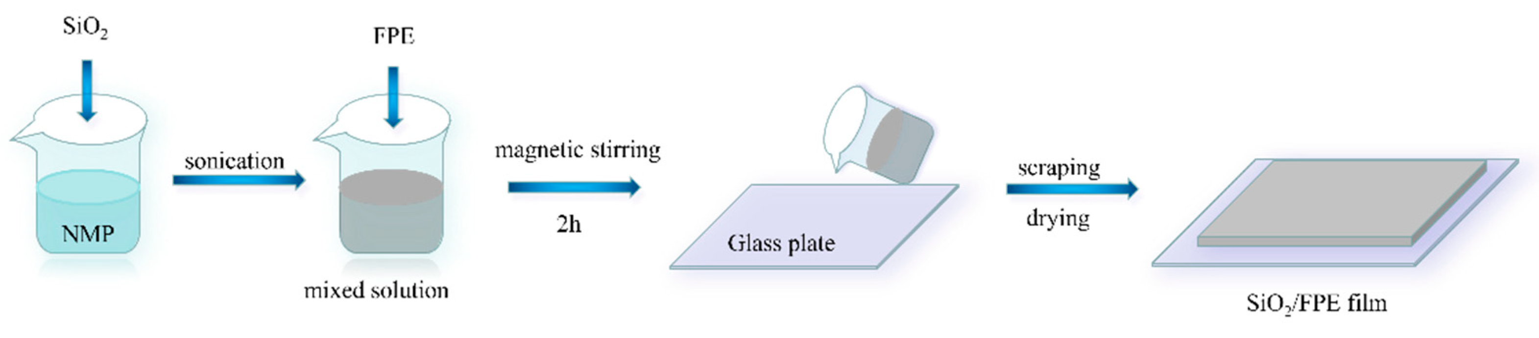
2.2. Preparations
2.3. Characterizations
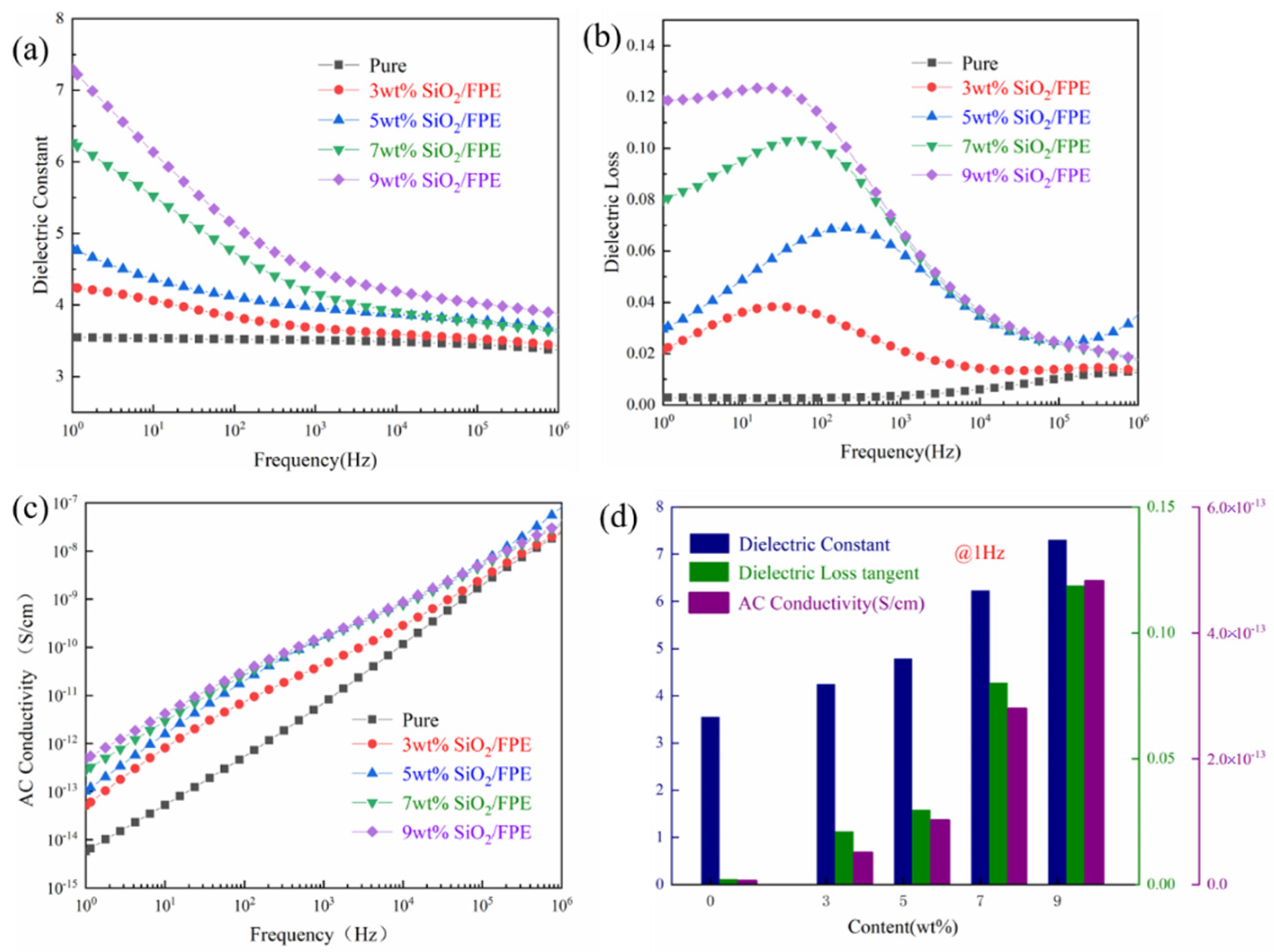
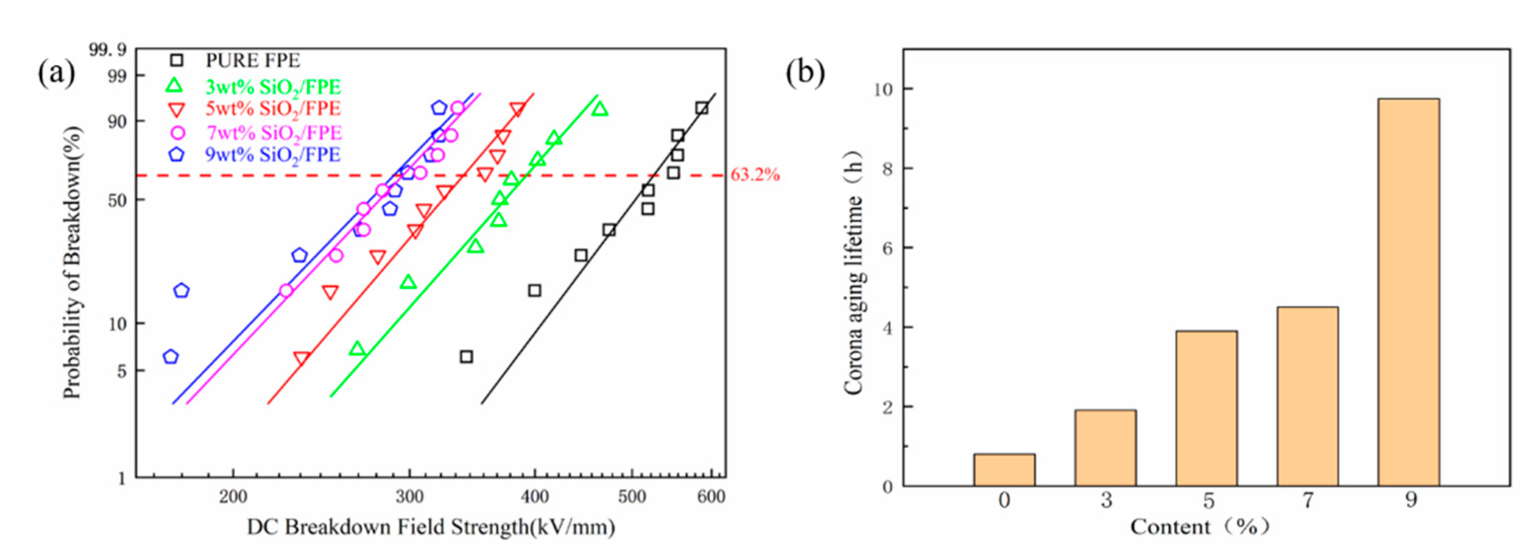
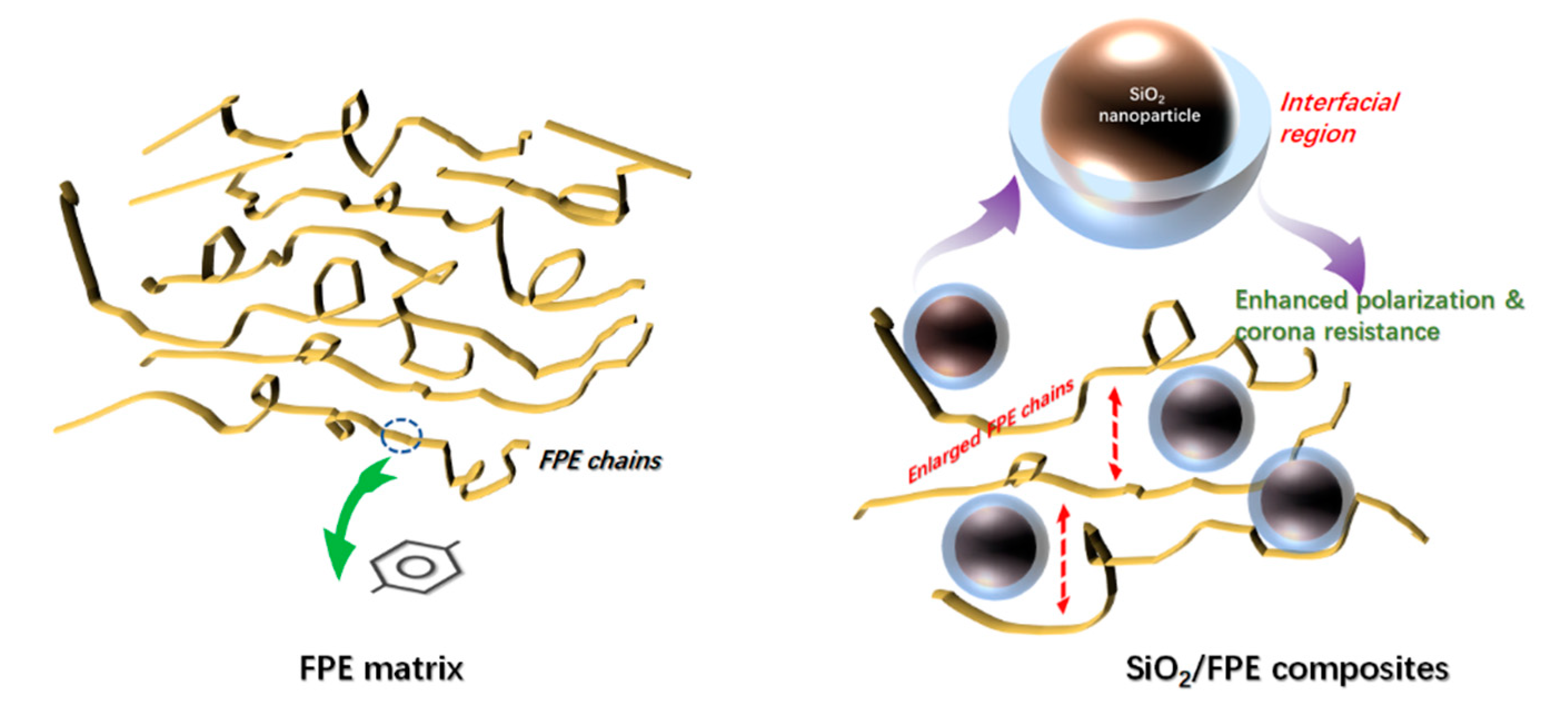
3. Results and Discussion
4. Conclusions
Supplementary Materials
Author Contributions
Funding
Institutional Review Board Statement
Informed Consent Statement
Data Availability Statement
Acknowledgments
Conflicts of Interest
References
- Bell, A.J. Ferroelectrics: The role of ceramic science and engineering. J. Eur. Ceram. Soc. 2008, 28, 1307–1317. [Google Scholar] [CrossRef]
- Bai, H.; Zhu, K.; Wang, Z.; Shen, B. 2D Fillers Highly Boost the Discharge Energy Density of Polymer-Based Nanocomposites with Trilayered Architecture. Adv. Funct. Mater. 2021. [Google Scholar] [CrossRef]
- Irvine, J.T.S.; Sinclair, D.C.; West, A.R. Electroceramics: Characterization by impedance spectroscopy. Adv. Mater. 1990, 2, 132–138. [Google Scholar] [CrossRef]
- Zhang, M.; Li, B.; Wang, J.J.; Huang, H.B.; Zhang, L.; Chen, L.Q. Polymer Dielectrics with Simultaneous Ultrahigh Energy Density and Low Loss. Adv. Mater. 2021, 33, 2008198. [Google Scholar] [CrossRef]
- Li, J.L.; Yin, J.H.; Ji, T.Y.; Feng, Y.; Liu, Y.U.; Zhao, H.; Li, Y.P.; Zhu, C.C.; Yue, D.; Su, B.; et al. Microstructure evolution effect on high-temperature thermal conductivity of LDPE/BNNS investigated by in-situ SAXS. Mater. Lett. 2019, 234, 74–78. [Google Scholar] [CrossRef]
- Lee, P.M.; Wang, Z.M.; Liu, X.X.; Chen, Z.; Liu, E.J. Glassy carbon electrode modified by graphene–gold nanocomposite coating for detection of trace lead ions in acetate buffer solution. Thin Solid Films 2015, 584, 85–89. [Google Scholar] [CrossRef]
- Zhao, H.; Yin, J.H.; Liu, X.X.; Feng, Y.; Liu, Y.Y.; Li, J.L.; Li, Y.P.; Yue, D.; Zhu, C.C. Polyimide-Based Composite Film Synergistically Modulated via a Nano-Micro Multidimensional Filler System toward Insulation Flexible Device Applications. Macromol. Chem. Phys. 2021, 222, 2000376. [Google Scholar] [CrossRef]
- Li, Q.; Han, K.; Gadinski, M.R.; Zhang, G.; Wang, Q. High energy and power density capacitors from solution-processed ternary ferroelectric polymer nanocomposites. Adv. Mater. 2014, 26, 6244–6249. [Google Scholar] [CrossRef]
- Xie, B.; Wang, Q.; Zhang, Q.; Liu, Z.Y.; Lu, J.S.; Zhang, H.B.; Jiang, S.L. High Energy Storage Performance of PMMA Nanocomposites Utilizing Hierarchically Structured Nanowires Based on Interface Engineering. ACS Appl. Mater. Interfaces 2021, 13, 27382–27391. [Google Scholar] [CrossRef]
- Hao, J.; Li, N.; Ma, X.X.; Liu, X.X.; Li, Y.; Xu, H.B.; Zhao, J.P. Ionic liquid electrodeposition of germanium/carbon nanotube composite anode material for lithium ion batteries. Mater. Lett. 2015, 144, 50–53. [Google Scholar] [CrossRef]
- Liu, X.X.; Chao, D.L.; Su, D.P.; Liu, S.K.; Chen, L.; Chi, C.X.; Lin, J.Y.; Shen, Z.X.; Zhao, J.P.; Mai, L.Q.; et al. Graphene nanowires anchored to 3D graphene foam via self-assembly for high performance Li and Na ion storage. Nano Energy 2017, 37, 108–117. [Google Scholar] [CrossRef]
- Zhang, T.D.; Yin, C.; Zhang, C.H.; Feng, Y.; Li, W.L.; Chi, Q.G.; Chen, Q.G.; Fei, W.D. Self-polarization and energy storage performance in antiferroelectric-insulator multilayer thin films. Compos. Part B 2021, 221, 109027. [Google Scholar] [CrossRef]
- Wahab, M.A.; Karim, M.R.; Aijaz, M.; Salahuddin, B.; Aziz, S.; Sina, A.A.I. A Study on the Interfacial Compatibility, Microstructure and Physico-Chemical Properties of Polyimide/Organically Modified Silica Nanocomposite Membrane. Polymers 2021, 13, 1328. [Google Scholar] [CrossRef]
- Chen, J.; Wang, Y.F.; Chen, W.X. Excellent comprehensive energy storage capabilities achieved in linear polymer composites via inserting acrylic rubber dielectric elastomers. J. Mater. Chem. C 2021, 9, 5000–5007. [Google Scholar] [CrossRef]
- Egerton, L.; Dillon, D.M. Piezoelectric and Dielectric Properties of Ceramics in the System Potassium—Sodium Niobate. J. Am. Ceram. Soc. 2010, 42, 438–442. [Google Scholar] [CrossRef]
- Arlt, G.; Hennings, D.; With, G. Dielectric properties of fine-grained barium titanate ceramics. J. Appl. Phys. 1985, 58, 1619–1625. [Google Scholar] [CrossRef] [Green Version]
- Leu, C.M.; Chang, Y.T.; Wei, K.H. Polyimide-Side-Chain Tethered Polyhedral Oligomeric Silsesquioxane Nanocomposites for Low-Dielectric Film Applications. Chem. Mater. 2003, 15, 2261–2265. [Google Scholar] [CrossRef] [Green Version]
- Liu, C.J.; Mei, M.; Pei, X.L.; Huang, X.B.; Wei, C. Aromatic polyimides with tertbutyl-substituted and pendent naphthalene units: Synthesis and soluble, transparent properties. Chin. J. Polym. Sci. 2015, 33, 1074–1085. [Google Scholar] [CrossRef]
- Li, Q.; Yao, F.Z.; Liu, Y.; Zhang, G.Z.; Wang, H.; Wang, Q. High-Temperature Dielectric Materials for Electrical Energy Storage. Annu. Rev. Mater. Res. 2018, 48, 219–243. [Google Scholar] [CrossRef]
- Li, H.; Ren, L.L.; Ai, D.; Han, Z.B.; Liu, Y.; Yao, B.; Wang, Q. Ternary polymer nanocomposites with concurrently enhanced dielectric constant and breakdown strength for high-temperature electrostatic capacitors. InfoMat 2020, 2, 389–400. [Google Scholar] [CrossRef] [Green Version]
- Li, Q.; Chen, L.; Gadinski, M.R.; Zhang, S.H.; Zhang, G.Z.; Li, H.Y.; Lagodkine, E.; Haque, A.; Chen, L.Q.; Jacken, T.N.; et al. Flexible high-temperature dielectric materials from polymer nanocomposites. Nature 2015, 523, 576–579. [Google Scholar] [CrossRef]
- Lewis, T.J. Nanometric dielectrics. IEEE Trans. Dielectr. Electr. Insul. 1994, 1, 812–825. [Google Scholar] [CrossRef]
- Roy, M.; Nelson, J.K. Polymer nanocomposite dielectrics-the role of the interface. IEEE Trans. Dielectr. Electr. Insul. 2005, 12, 629–643. [Google Scholar] [CrossRef]
- Tanaka, T.; Kozako, M.; Fuse, N.; Ohki, Y. Proposal of a multi-core model for polymer nanocomposite dielectrics. IEEE Trans. Dielectr. Electr. Insul. 2005, 12, 669–681. [Google Scholar] [CrossRef]
- Wang, J.Y.; Yang, S.Y.; Huang, Y.L.; Tien, H.W.; Chin, W.K.; Ma, C.C.M. Preparation and properties of graphene oxide/polyimide composite films with low dielectric constant and ultrahigh strength via in situ polymerization. J. Mater. Chem. 2011, 21, 13569–13575. [Google Scholar] [CrossRef]
- Liu, X.X.; Yin, J.H.; Kong, Y.; Chen, M.H.; Feng, Y.; Wu, Z.H.; Su, B.; Lei, Q.Q. The property and microstructure study of polyimide/nano-TiO2 hybrid films with sandwich structures. Thin Solid Films 2013, 544, 54–58. [Google Scholar] [CrossRef]
- Roy, M. An Examination of the Potential for Nano-Composites in the Formulation of HV Cable Insulation. Ph.D. Thesis, Rensselaer Polytechnic Institute, Troy, NY, USA, 2005. [Google Scholar]
- Irwin, P.C.; Cao, Y.; Bansal, A.; Schadler, L.S. Property evaluation of nanofilled polymers. In Proceedings of the 26th International Power Modulator Symposium and 2004 High Voltage Workshop, San Francisco, CA, USA, 23–26 May 2005. [Google Scholar] [CrossRef]
- Zhang, J.; Zhu, B.K.; Chu, H.J.; Xu, Y.Y. Silica/polyimide hybrids and their dielectric properties. I. Preparation with an improved sol–gel process with poly (amic acid) as the precursor. J. Appl. Polym. Sci. 2010, 97, 20–24. [Google Scholar]
- Wang, S.J.; Zha, J.W.; Li, W.K.; Wang, Q.; Wen, Y.Q.; Chen, Y.Q.; Chen, G.; Dang, Z.M. Influence of hierarchy structure on electrical properties of gradient-distribution aluminum oxide/polyethylene nanocomposites. Compos. Sci. Technol. 2016, 135, 100–105. [Google Scholar] [CrossRef] [Green Version]
- Gu, J.W.; Meng, X.D.; Tang, Y.S.; Li, Y.; Zhuang, Q.; Kong, J. Hexagonal boron nitride/polymethyl-vinyl siloxane rubber dielectric thermally conductive composites with ideal thermal stabilities. Compos. Part A 2017, 92, 27–32. [Google Scholar] [CrossRef]
- Bian, W.C.; Yao, T.; Chen, M.; Zhang, C.; Shao, B.; Yang, Y. The synergistic effects of the micro-BN and nano-Al2O3 in micro-nano composites on enhancing the thermal conductivity for insulating epoxy resin. Compos. Sci. Technol. 2018, 168, 420–428. [Google Scholar] [CrossRef]
- Li, Y.; Fu, S.Y.; Li, Y.Q.; Pan, Q.Y.; Xu, G.; Yue, C.Y. Improvements in transmittance, mechanical properties and thermal stability of silica-polyimide composite films by a novel sol-gel route. Compos. Sci. Technol. 2015, 68, 293–301. [Google Scholar]
- Shang, Z.P.; Liu, C.L.; Lv, X.D.; Gao, L.X. Synthesis and properties of silica–polyimide hybrid films derived from colloidal silica particles and polyamic acid. J. Appl. Polym. Sci. 2008, 109, 3477–3483. [Google Scholar] [CrossRef]
- Chen, B.B.; Li, X.F.; Li, X.; Jia, Y.H.; Yang, J.; Li, C.S. Hierarchical carbon fiber-SiO2 hybrid/polyimide composites with enhanced thermal, mechanical, and tribological properties. Polym. Compos. 2018, 39, E1626–E1634. [Google Scholar] [CrossRef]
- Chen, M.H.; Zhou, J.W.; Zhang, J.W.; Chen, Q.G. Dielectric Property and Space Charge Behavior of Polyimide/Silicon Nitride Nanocomposite Films. Polymers. 2020, 12, 322. [Google Scholar] [CrossRef] [Green Version]
- Yong, F.; Bu, W.B.; Liu, X.X.; Cheng, W.D.; Wu, Z.H.; Yin, J.H. Research on interface and fractal characteristics of PI/Al2O3 Films by SAXS. Acta Phys. Sin. 2011, 60, 056101. [Google Scholar]
- Zhang, X.L.; Liu, X.X.; Yang, C.; Li, N.; Ji, T.Y.; Yan, K.; Zhu, B.; Yin, J.H.; Zhao, J.P.; Li, Y. A V2O5-nanosheets-coated hard carbon fiber fabric as high-performance anode for sodium ion battery. Surf. Coat. Technol. 2019, 385, 661–666. [Google Scholar] [CrossRef]
- Li, Z.H.; Gong, Y.J.; Wu, D.; Sun, Y.H.; Wang, J.; Liu, Y.; Dong, B.Z. SAXS analysis of interface in organo-modified mesoporous silica. Surf. Interface Anal. 2001, 31, 897–900. [Google Scholar] [CrossRef]
- Li, T.; Senesi, A.J.; Lee, B. Small Angle X-ray Scattering for Nanoparticle Research. Chem. Rev. 2016, 116, 11128–11180. [Google Scholar] [CrossRef]
- Li, Z.H.; Wu, Z.H.; Mo, G.; Xing, X.Q.; Liu, P. A small-angle x-ray scattering station at beijing synchrotron radiation facility. Instrum. Sci. Technol. 2014, 42, 128–141. [Google Scholar] [CrossRef]
- Zhou, L.R.; Wu, G.N.; Gao, B.; Zhou, K.; Liu, J.; Chao, K.J.; Zhou, L.J. Study on charge transport mechanism and space charge characteristics of polyimide films. IEEE Trans. Dielectr. Electr. Insul. 2009, 16, 1143–1149. [Google Scholar] [CrossRef]
- Soares, B.G.; Leyva, M.E.; Barra, G.M.O.; Khastgir, D. Dielectric behavior of polyaniline synthesized by different techniques. Eur. Polym. J. 2006, 42, 676–686. [Google Scholar] [CrossRef]
- Fattoum, A.; Gmati, F.; Bohli, N.; Arous, M.; Mohamed, A.B. Effects of the matrix molecular weight on conductivity and dielectric relaxation in plasticized polyaniline/polymethyl methacryla the blends. J. Phys. D: Appl. Phys. 2008, 41, 095407. [Google Scholar] [CrossRef]
- Feng, Y.; Li, W.L.; Hou, Y.F.; Yu, Y.; Cao, W.P.; Zhang, T.D.; Fei, W.D. Enhanced dielectric properties of PVDF-HFP/BaTiO3-nanowire composites induced by interfacial polarization and wire-shape. J. Mater. Chem. C. 2015, 3, 1250–1260. [Google Scholar] [CrossRef]


Publisher’s Note: MDPI stays neutral with regard to jurisdictional claims in published maps and institutional affiliations. |
© 2021 by the authors. Licensee MDPI, Basel, Switzerland. This article is an open access article distributed under the terms and conditions of the Creative Commons Attribution (CC BY) license (https://creativecommons.org/licenses/by/4.0/).
Share and Cite
Zhang, W.; Zhao, K.; Guan, F.; Yin, J.; Feng, Y.; Li, J.; Li, Y. Microstructure and Electrical Properties of Fluorene Polyester Based Nanocomposite Dielectrics. Polymers 2021, 13, 3053. https://doi.org/10.3390/polym13183053
Zhang W, Zhao K, Guan F, Yin J, Feng Y, Li J, Li Y. Microstructure and Electrical Properties of Fluorene Polyester Based Nanocomposite Dielectrics. Polymers. 2021; 13(18):3053. https://doi.org/10.3390/polym13183053
Chicago/Turabian StyleZhang, Wenchao, Kuo Zhao, Feng Guan, Jinghua Yin, Yu Feng, Jialong Li, and Yanpeng Li. 2021. "Microstructure and Electrical Properties of Fluorene Polyester Based Nanocomposite Dielectrics" Polymers 13, no. 18: 3053. https://doi.org/10.3390/polym13183053