1. Introduction
Nowadays, laminated composite parts are extensively used in engineering structures since they have desirable mechanical properties such as high specific stiffness and strength. On the other hand, various damage modes occur in these materials, e.g., fiber/matrix debonding, matrix cracking, fiber breakage, and delamination can restrict their applications [
1,
2].
Among these failure modes, removing or at least decreasing the delamination problem attracts the attention of more researchers. One of the effective ways to reduce or delay the delamination is to apply nanofiber mats between the composite layers [
3,
4]. The considerations prove that the nanofibers can increase the interfacial fracture toughness, strength, and resistance to delamination under static, fatigue, and impact loadings. This fact is due to the unique properties of these nanofiber mats, such as high surface-to-volume contact ratio, flexibility, and suitable mechanical properties [
5].
The first research on the effect of applying nanofibers between composite layers was carried out by Dizenis and Ranker [
6]. They showed that the use of nanofibers between layers of composite parts increases interlayer toughness, strength, and delamination resistance without significantly reducing the sheet properties of the layers and increasing structural weight.
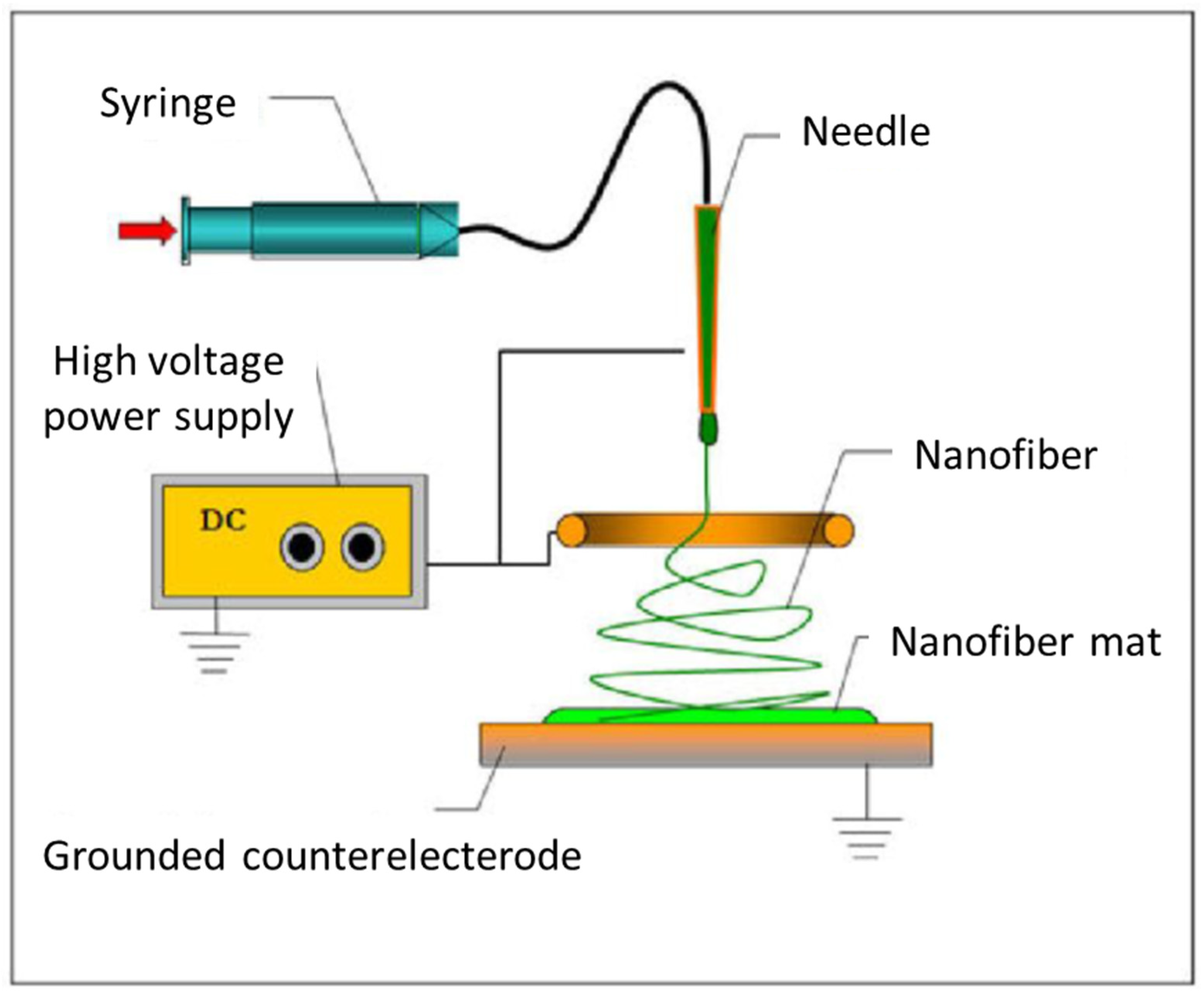
Electrospinning is a well-known method of producing nanofiber mats which are interleaved between composite layers for increasing interlayer toughness, strength, and delamination resistance. Saghafi et al. have used electrospinning to produce interlaminar 66 nylon, polycopperlatone (PCL), and a combination of these two nanofiber mats. They have investigated the energy reduction rate of mode I and mode II in their study [
7]. Zhang et al. [
8] have conducted a research to obtain suitable parameters for electrospinning nanofibers of PCL, polyvinylidene fluoride (PVDF), and polyacrylonitrile (PAN). They have used mechanical tests such as mode I test to obtain mechanical properties and to prove the efficiency of applying nanofibers in increasing the interfacial fracture toughness of mode I.
Although delamination is a common failure mechanism in composite structures, other damage mechanisms such as matrix cracking, fiber/matrix debonding, and fiber breakage can similarly significantly affect the functionality aspects of the structure. Interleaving nanofiber mats between the layers of a composite structures not only decreases the delamination (and thus increases interlayer toughness), but also decreases other failure mechanisms. Thus, it can be beneficial to investigate the effect of nanofibers on failure mechanisms other than delamination.
Acoustic emission (AE) is a non-destructive technique that can be used to investigate the failure mechanisms in laminated composite structures [
9]. AE signals are high frequency sound waves which are produced as a result of strain energy release due to internal events such as damaged mechanisms during the deformation of a material or a structure [
10]. The recorded AE signals may be analyzed to investigate and to determine different failure mechanisms [
11]. Most of AE, such as peak frequency, counts, energy, and amplitude, are related to user-defined parameters such as hit definition time, peak definition time, and threshold level, which, by using AE waveform-based analyzing methods such as wavelet transform and Shannon’s entropy, can be reduced to the effect of user-defined parameters [
12]. Saeedifar et al. [
11] have utilized the AE method to investigate the behavior of delamination propagation and to evaluate the critical value of the strain energy in mode I, mode II, and mixed mode tests. In order to identify interlaminar fracture toughness, they have used ASTM standard methods, FEM analysis, the AE method, and sentry function. They showed that the G
C values obtained by the sentry function method and FEM analysis are in a close agreement with the results of nonlinear methods, which are recommended in the ASTM standards. Gholizadeh et al. [
3] utilized AE method for considering the effect of Nylon 66 on different damage modes under mode I and mode II loadings. For analyzing AE signals, they have used a peak frequency-based method and wavelet transform. AE analysis showed the significant reduction of different damage modes in the nanomodified laminates.
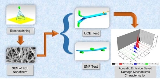
As mentioned, determining the effect of nanofibers on different failure mechanisms is an essential step in designing composite materials. Thus, in this study, PCL elecrospun nanofiber mats were interleaved between glass/epoxy composite layers, and the effect of nanofibers on matrix cracking, fiber/matrix debonding, and fiber breakage failure mechanisms was investigated by means of AE. In order to achieve this, mode I and mode II fracture tests were carried out and AE signals were recorded during mode I tests. Three methods, including the conventional method, Wavelet Packet Transform (WPT), and sentry function, were used for analyzing AE signals and determining the effect of interleaving nanofibers on different damage mechanics.
3. Results and Discussion
The load–displacement diagram of mode I that tests for both nano modified and reference samples is shown in
Figure 10. It can be concluded from this diagram that taking advantage of nanofibers increases the required load for crack growth in mode I test. According to these results, the amount of critical strain energy release rates (
GIC) for nanomodified and reference are 0.58 and 0.42
, respectively. Thus, the
GIC amount of the specimen with nanofibers has increased by about 38% compared to specimen without nanofibers.
The load–displacement diagram of the mode II tests is shown in
Figure 11. According to this diagram, the maximum applied load for nanomodified and reference sample is about 827 and 625, respectively, and the critical strain energy release rates of the mode II test (
GIIC) for the nanomodified and reference samples are 3.96 and 2.6, respectively. Thus, using nanofibers caused a 52% and 32% increase in critical strain energy release rates and maximum applied load, respectively.
As shown in
Figure 12, due to the AE signals, each of the mode I tests can be divided in to three areas. In area (I), an elastic behavior with a linear increase in load can be observed, while no sensible signals are recorded. In zone (II), some initial damages such as matrix cracking occur. Due to these initial damages, the specimen loses some stiffness, which leads to the load diagram slope decreasing, and some AE signals with a low amount of energy are recorded. Finally, in zone (III), the crack begins to propagate and all the damaged mechanisms (including matrix cracking, matrix/fiber debonding, fiber breakage, and delamination) occur. Due to these damage mechanisms, load diagram drops, and many AE signals with different energies are produced. According to
Figure 12, in all three zones, including nanofiber, cause an increase in the amount of the maximum applied load.
In
Figure 13, the crack growth and AE cumulative count–displacement diagrams for both reference and nanomodified samples can be seen. It can be concluded from these diagrams that, in both reference and nanomodified specimens, cumulative count and crack growth are related. In other words, when the crack growth rate increases, the rate of the cumulative count rises as well. Accordingly, comparing the AE cumulative counts of the two diagrams of
Figure 13 reveals the fact that utilizing PCL nanofibers causes a decrease in this parameter, because nanofibers decrease the amount of damages that occur during the test.
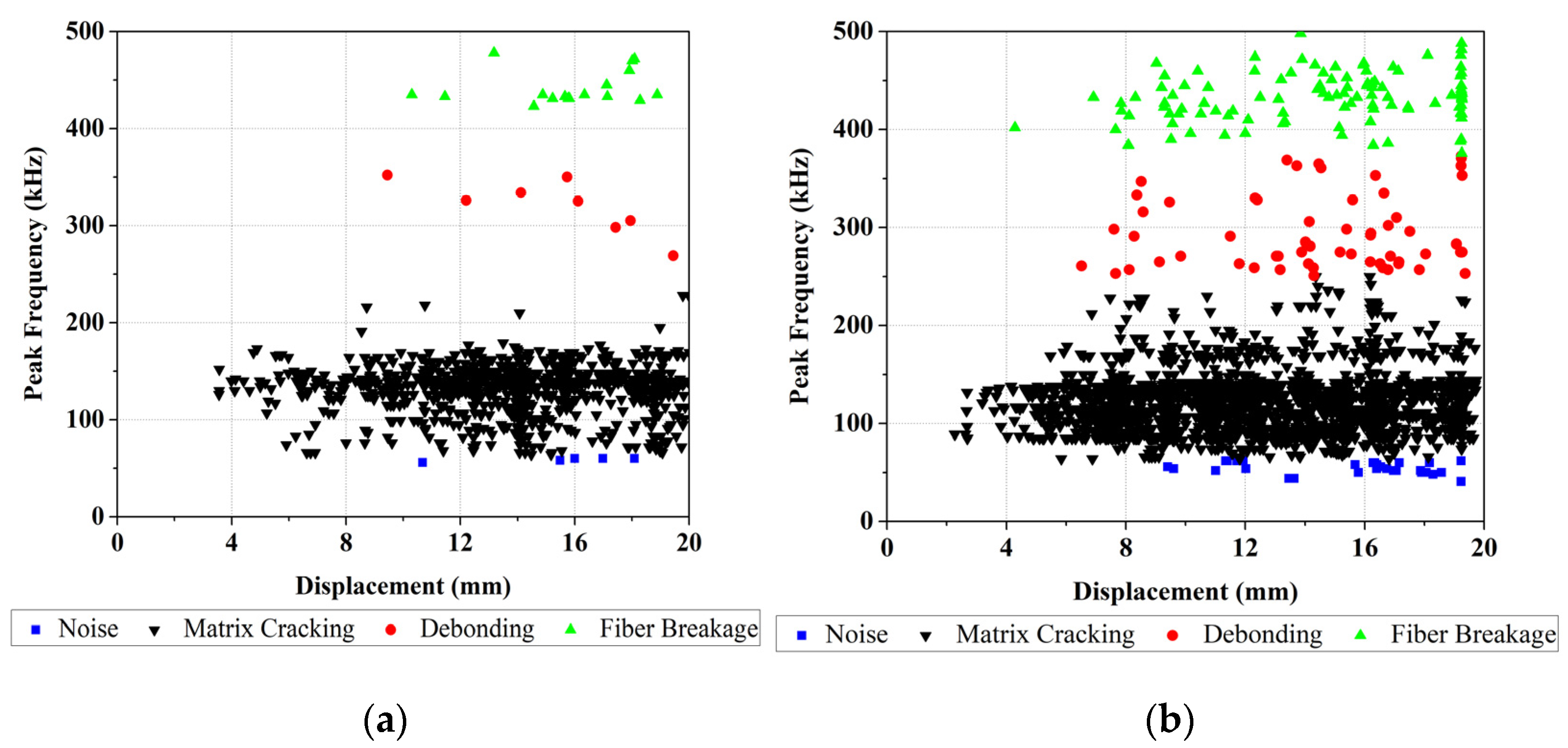
The peak frequency of recorded AE signals (P.Freq) of both reference and nanomodified laminates tests are shown in
Figure 14. In the conventional method, peak frequency is one of the AE signal parameters used for determining the type of damage. As mentioned, peak frequencies between 62.5 and 250 kHz refer to matrix cracking, between 250 and 375 kHz are related to fiber/matrix debonding, and those in the range from 375 to 500 kHz belong to fiber breakage [
18]. According to this classification, for showing these damage mechanisms, each diagram in
Figure 14 is classified into three zones. By considering these results, the amount of AE events of different damage mechanisms for both reference and nanomodified specimens are shown in
Table 1. According to these results, in the DCB tests, applying PCL nanofibers reduces matrix cracking, matrix/fiber debonding, and fiber breakage damage mechanisms by about 75%, 94%, and 79%, respectively. As a result, PCL nanofibers causes a significant decrease in fiber/matrix debonding mechanism.
WPT is another method which is applied in this study for analyzing AE signals that are recorded during mode I tests. Here, each waveform of the AE signals is decomposed into three levels and eight wavelet components based on their frequency ranges. In order to specify the peak frequency range of each component, the Fast FFT is used. Matlab software is used in calculating and analyzing each waveform of the recorded AE signals.
The FFT results for nanomodified and reference specimens are illustrated in
Figure 15 and
Figure 16, respectively. In both diagrams, the first component has a peak frequency between 0 and 62.5 kHz that is related to environmental noise. The second, third, and forth components have a peak frequency between 62.5 and 250 kHz, therefore these components can be interpreted as indicative of a matrix cracking failure mechanism. The fifth and sixth components are considered to be fiber/matrix debonding, since the peak frequency of these components has been located in the range of 250 to 375 kHz. The last two components have a peak frequency between 375 and 500 kHz, which are related to the fiber breakage failure mechanism. The energy of each component is then determined by means of energy criteria. The amount of energy for each component for both nanomodified and reference laminates are shown in
Figure 17 and
Figure 18, respectively. The quantity of each failure mechanism can be specified by considering the AE energy distribution in each damage frequency range for both specimens. The quantity of energy for each failure mechanism for both specimens, nanomodified and reference, are compared in
Table 2. According to the results obtained by the WPT method, applying PCL nanofibers in mode I test causes a reduction in matrix cracking, fiber/matrix debonding, and fiber breakage failure mechanisms by 91%, 67%, and 93%, respectively.
In
Table 3, the results of the PCL nanofiber’s effect on the damage mechanisms’ reduction, based on conventional (peak frequency) and WPT analyzing methods, are compared. According to these results, both methods of analysis indicate that PCL nanofibers cause a significant reduction in all three dominant failure mechanisms. However, the predicted amount of this reduction in each failure mechanism is different, based on the analyzing method.
Sentry function and load displacement diagrams for both reference and nanomodified samples are shown in
Figure 19. As can be seen in these diagrams, the amount of the first sudden drop of the sentry function in the reference specimen is larger than in the nanomodified samples, which indicates that, in the reference specimen, the amount of energy due to failure mechanisms that cause primary crack propagation is more than that found in the nanomodified specimens. After the first drop in the sentry function curve, in the nanomodified sample, the range of the increasing trend (P
I) and the constant behavior (P
III) are larger than the reference sample, whereas the range of the sudden drop (P
II) in reference sample is wider than in the nanomodified sample. Thus, it can be concluded that, through this zone, the nanomodified sample is more resistant to crack propagation.
In
Figure 20, the sentry function of both nanomodified and reference samples are compared. As mentioned above, the integral of the sentry function, or, in the other words, the area under the sentry function–displacement curve, can be considered as a parameter of damage resistance capability. According to the results of
Figure 20, throughout the displacement, the sentry function for the reference sample passes below the nanomodified specimen. Thus, it can be concluded that the value of the integral of the sentry function related to the nanomodified specimen is higher than the reference sample. As a result, the nanomodified sample has a higher damage resistance capability.
4. Conclusions
In this study, the effect of using polycaprolatone nanofibers (PCL) in mode I and mode II fracture tests is investigated. Electrospinning method is used in order to produce PCL nanofibers. Mode I and mode II tests are conducted according to the relevant standards. In the nanomodified samples, a layer of PCL nanofibers was placed in front of the primary crack. Acoustic emission (AE) analysis is utilized with the aim of investigating the effect of including nanofibers on the failure mechanisms that occur during mode I tests. In order to analyze AE signals, three methods, including the conventional method, wavelet packet transform (WPT), and sentry function, are used. The following results are concluded from this study:
According to mechanical results, using PCL nanofibers causes the critical strain energy release rate of mode I and mode II to increase by about 38% and 52%, respectively. Moreover, the maximum applied load in mode II increases by about 32% in nanomodified laminates.
According to the conventional AE analyzing method, using PCL nanofibers results in a reduction in matrix cracking, fiber/matrix debonding, and fiber breakage failure mechanisms by 75%, 94%, and 79%, respectively, in mode I test.
The WPT method shows that, in mode I tests, the specimens which are modified by PCL nanofibers are involved, with a reduction of 91%, 67%, and 93% in matrix cracking, fiber/matrix debonding, and fiber breakage, respectively.
The inclusion of PCL nanofibers causes a decrease in both the amount and number of sudden drops in the sentry function results of mode I tests. On the other hand, nanomodified specimens experience higher amounts and numbers of increasing trends and constant behaviors of the sentry function. This proves that the PCL nanomodified laminates are significantly resistant to damage and, as a result, show a higher damage resistance capability.


