
An Optimum Fatigue Design of Polymer Composite Compressed Natural Gas Tank Using Hybrid Finite Element-Response Surface Methods

 ,
,  ,
, 
 and
and
Abstract
:1. Introduction
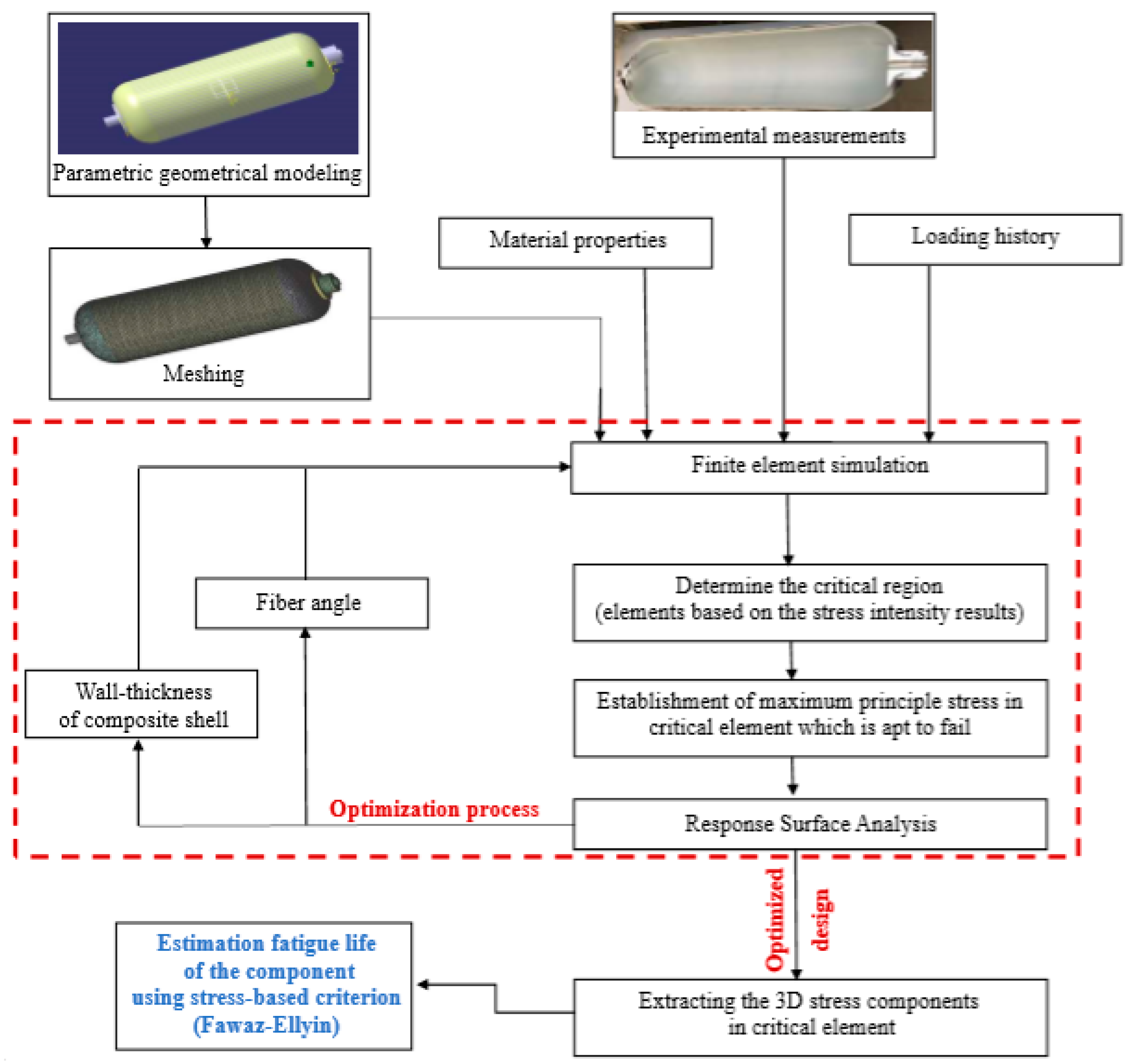
2. Methodology
3. Finite Element Simulation
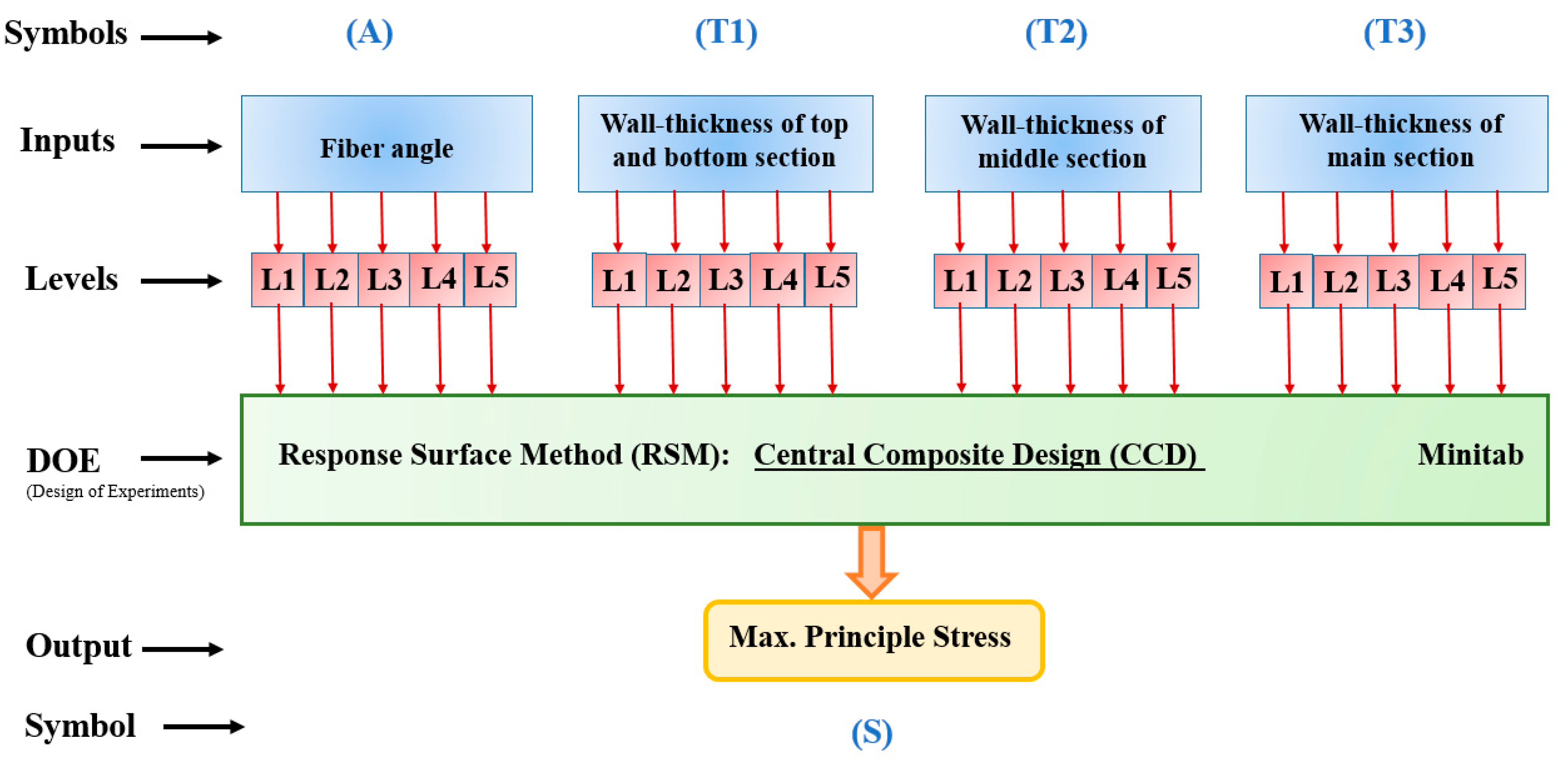
4. Response Surface Method
5. Results and Discussion
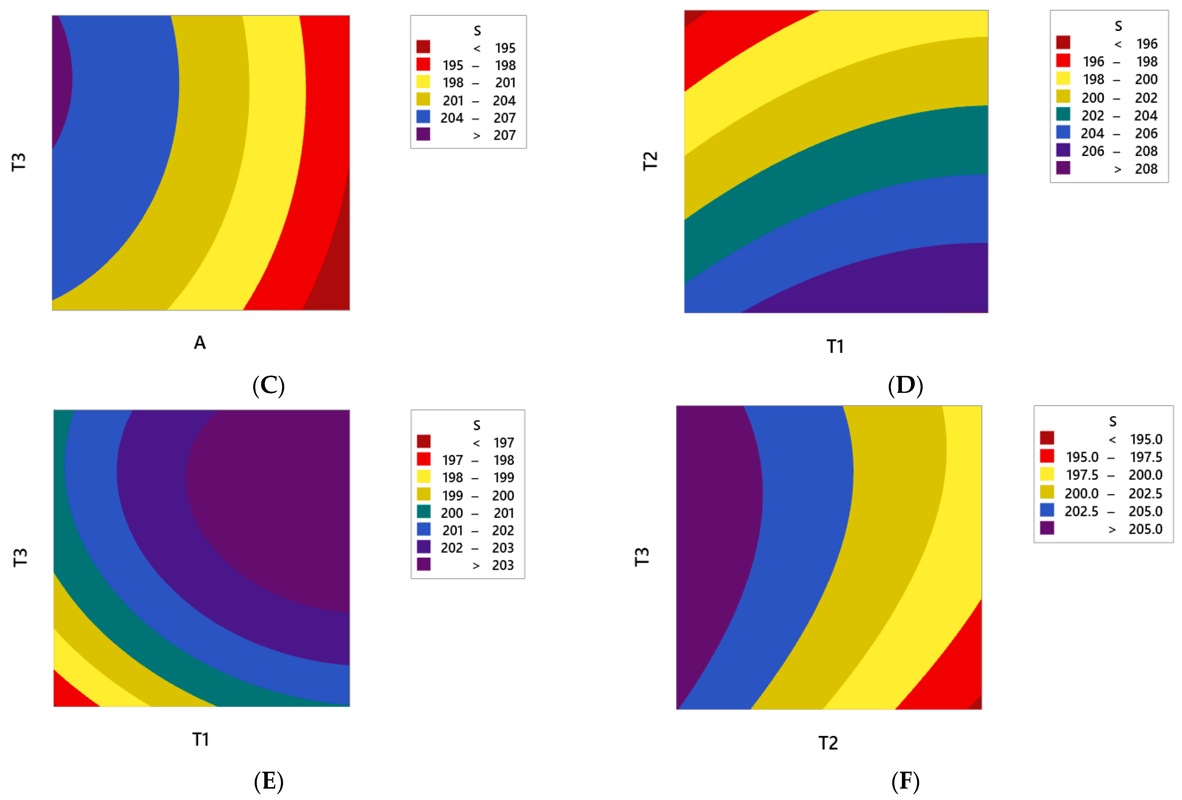
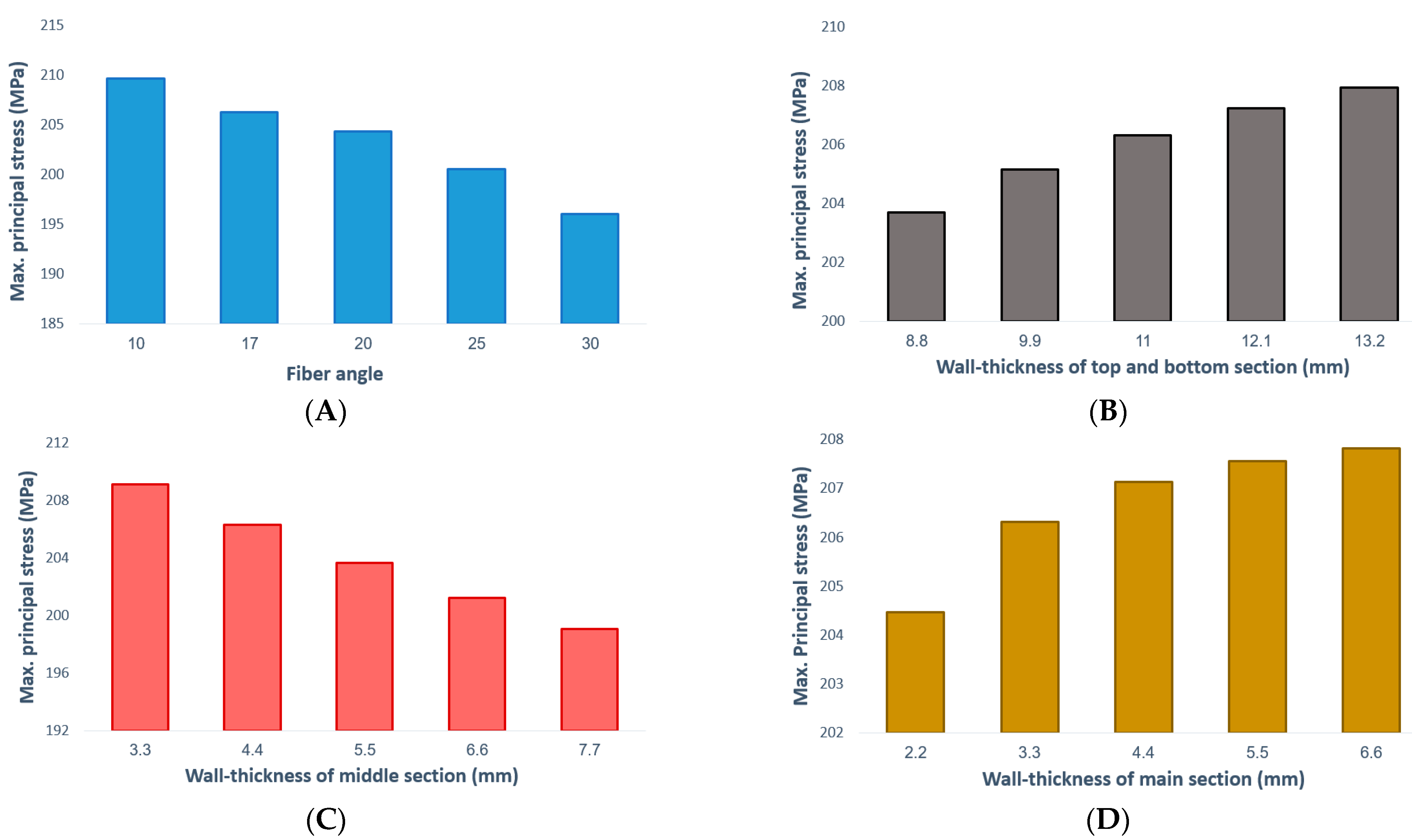
- The maximum principal stress always decreases by increasing the fiber angle. Therefore, it is recommended to consider the maximum level of fiber angle to achieve the maximum fatigue lifetime of the polymer composite CNG tank.
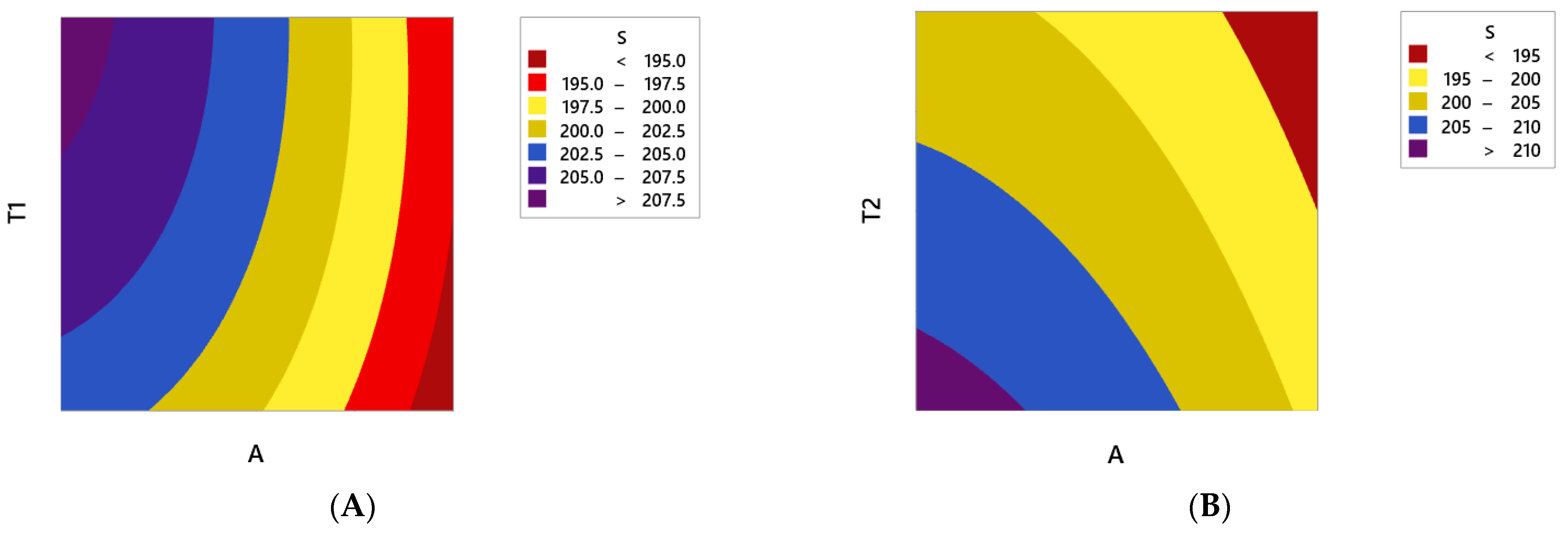
- In order to have the minimum principal stress in the polymer composite CNG tank, it is necessary to consider the maximum and minimum level settings for parameters of T2 and T1, respectively. On the other hand, it is better to make the composite shell thickness as uniform as possible in the two curved sections of the CNG tank.
6. Conclusions
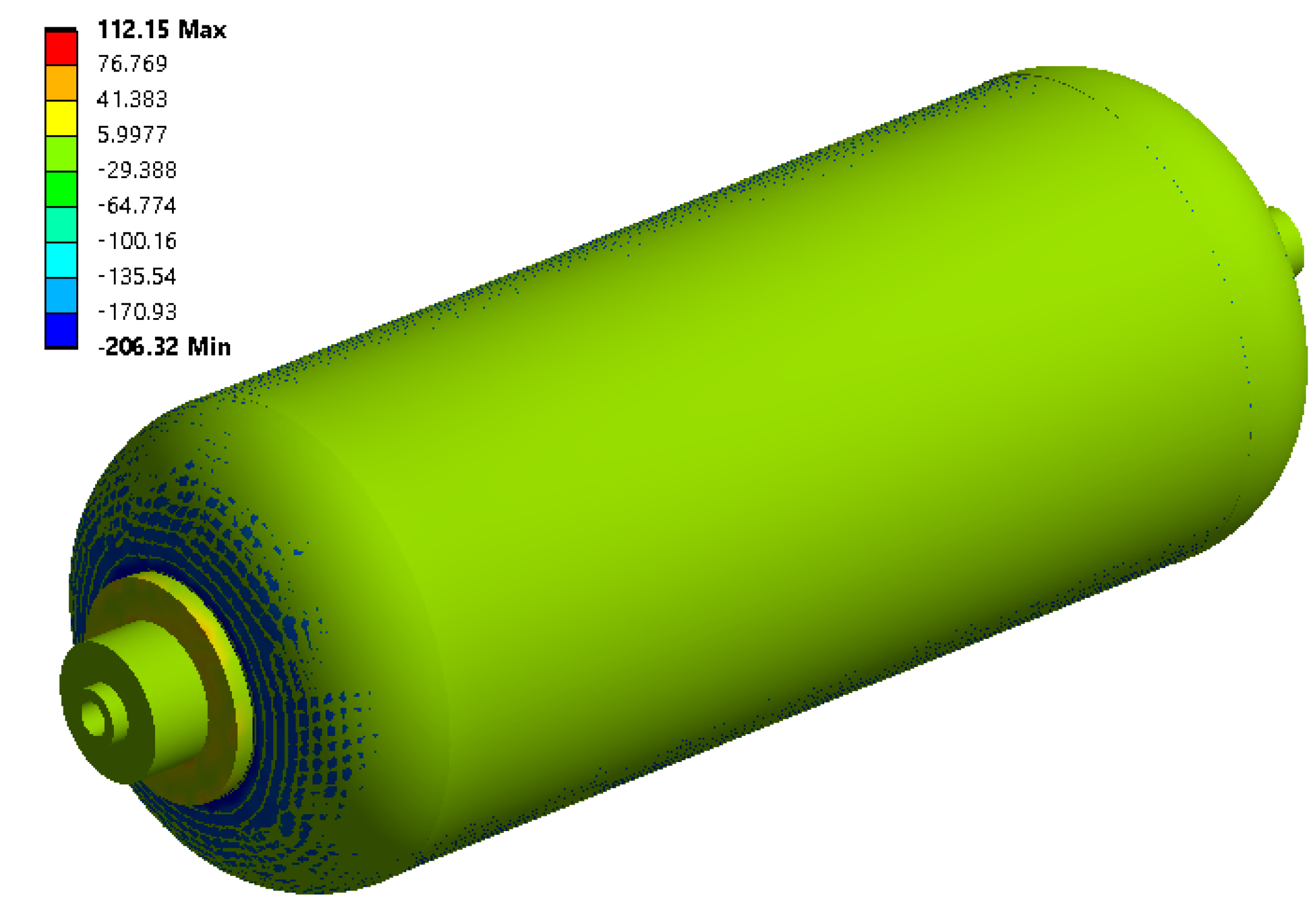
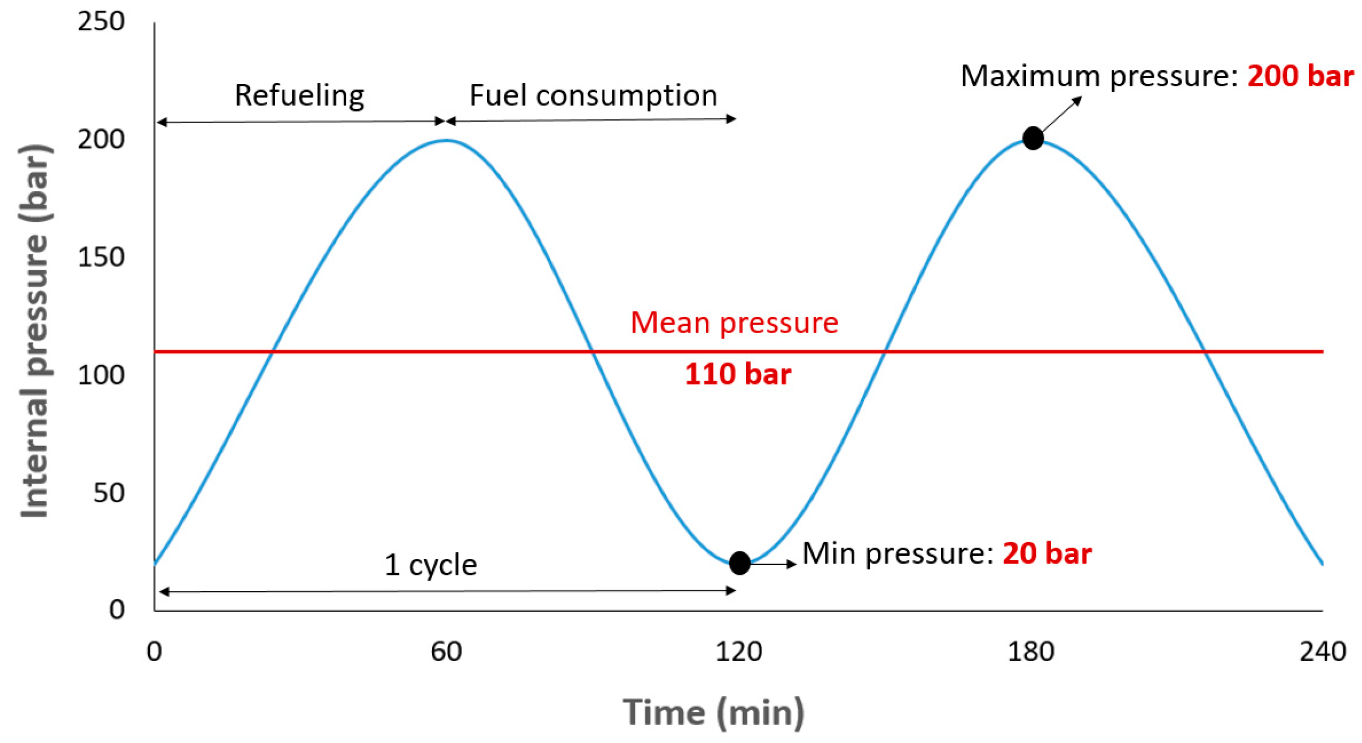
- The FE results indicate that the maximum principal stress created in the initial design of the CNG composite tank (A = 17, T1 = 11 mm, T2 = 4.4 mm, and T3 = 3.3 mm) under static load is about 206 MPa. Also, the fatigue life of the tank under variations of internal pressure (20–200 bar) is 89,841 cycles. It means that the number of refueling times without the risk of tank failure is equal to 89,841.
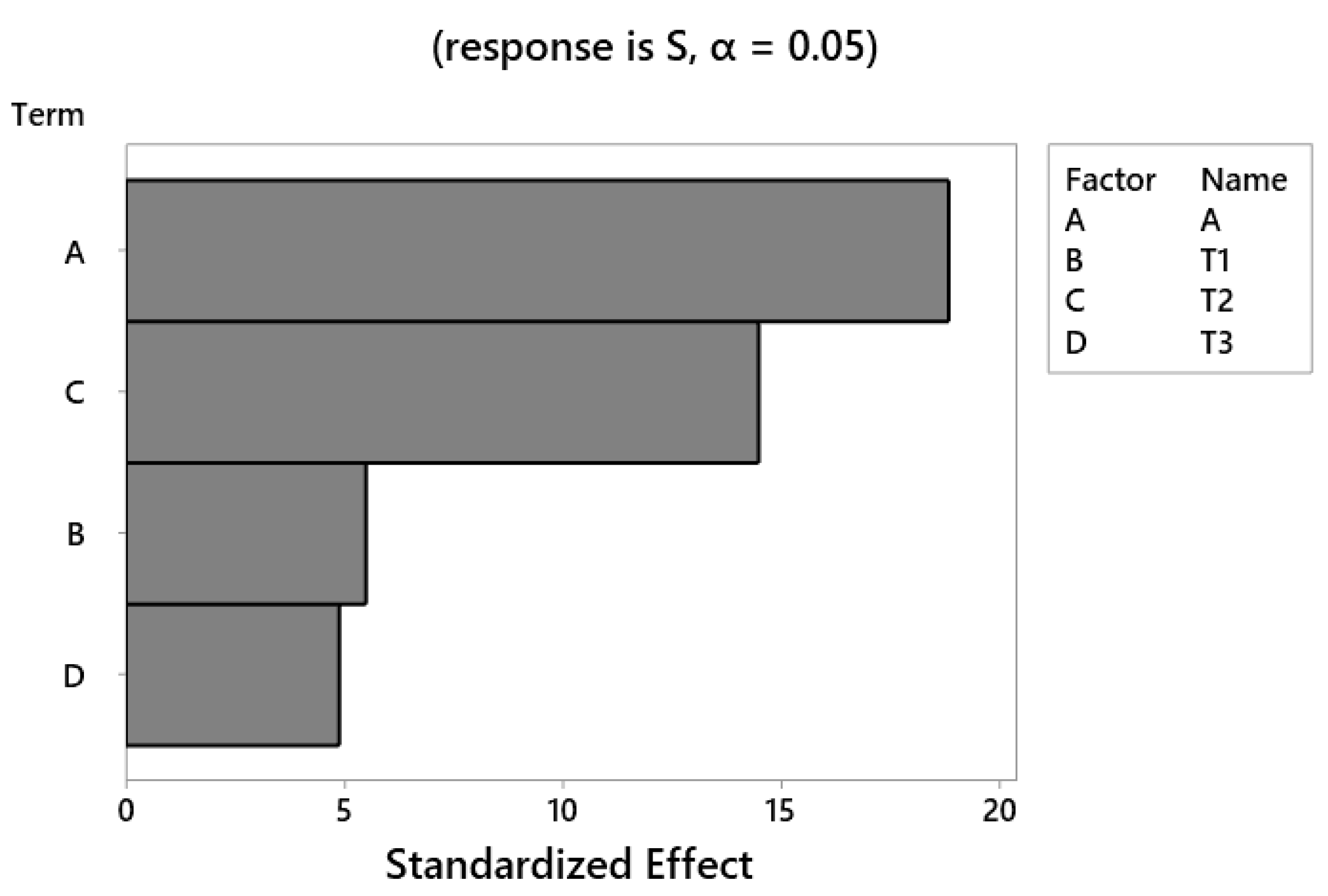
- The Pareto chart as a result of response surface analysis reveals that the most and least effective parameters on the stress level of the CNG composite tank are fiber angle and wall-thickness of the main section, respectively. Therefore, the authors strongly recommend to the manufacturers of Type-4 CNG fuel tanks to be more careful about the twist angle of the fibers in the manufacturing process to strengthen this super-critical component.
- The RSM results show that the maximum principal stress always decreases by increasing fiber angle. Therefore, it is recommended to consider the maximum level of the fiber angle to achieve the maximum fatigue lifetime of the composite CNG tank. Moreover, to have the minimum principal stress in the polymer composite CNG tank, it is necessary to consider the maximum and minimum level settings for parameters T2 and T1, respectively. On the other hand, it is better to make the thickness of the polymer composite shell as uniform as possible in the two curved sections of the CNG tank. In other words, to achieve a longer service life, it is necessary to try to build tanks with invariable thickness.
- Based on the optimization algorithm presented, the optimal parameters obtained for the tank are A = 30, T1 = 8.8 mm, T2 = 7.7 mm, and T3 = 2.2 mm. Also, the maximum principal stress and fatigue life related to the optimized tank are obtained about 185 MPa and 218,678 cycles, respectively.
- The findings of this research state that the maximum principal stress decreases by up to 10% and after that the fatigue life of the fuel tank increases about 2.4 times using optimal values of manufacturing process parameters. After confirmation of the results by pre-production tests, it can drastically reduce the financial losses and irreparable damages due to the fuel tank explosion.
Author Contributions
Funding
Institutional Review Board Statement
Informed Consent Statement
Data Availability Statement
Conflicts of Interest
References
- Sawant, T.; Purwant, N.K.; Kulkarni, S.; Karajagi, P. Design & Stress Analysis of a Hoop Wrapped CNG Composite Vessel with an SAE-4135 Low Alloy Steel Liner. Int. J. Eng. Res. 2016, 338–343. [Google Scholar]
- Heaidari-Rarani, M.; Ahmadi Jebeli, M. Finite element modeling of failure in IV type composite pressure vessel using WCM plug-in in ABAQUS software. Modares Mech. Eng. 2018, 18, 191–200. [Google Scholar]
- Agrawal, A.; Kumar, S. Fatigue life prediction of a Hoop-Wrapped composite CNG cylinder containing surface flow. Int. J. Emerg. Technol. Adv. Eng. 2014, 4, 790–796. [Google Scholar]
- Kim, E.S.; Choi, S.K. Risk analysis of CNG composite pressure vessel via computer-aided method and fractography. Eng. Fail. Anal. 2013, 27, 84–98. [Google Scholar] [CrossRef]
- Nouri, M.; Ashenai-Ghasemi, F.; Rahimi-Sherbaf, G.; Kashyzadeh, K.R. Experimental and Numerical Study of the Static Performance of a Hoop-Wrapped CNG Composite Cylinder Considering Its Variable Wall Thickness and Polymer Liner. Mech. Compos. Mater. 2020, 56, 339–352. [Google Scholar] [CrossRef]
- Seyedi, S.M.; Naddaf Oskouei, A.; Sayah Badkhor, M. Experimental, numerical and Optimization study of Composite Tanks with Non-Metallic Primer (CNG Fourth Type). Modares Mech. Eng. 2020, 20, 1789–1800. [Google Scholar]
- Reynaldo, A.; Pramono, H.S.; Santosa, S.P.; Aziz, M. Finite Element Analysis of Liquefied Ammonia Tank for Mobility Vehicles Employing Polymers and Composites. Energies 2020, 13, 5312. [Google Scholar] [CrossRef]
- Sapre, S.; Pareek, K.; Vyas, M. Investigation of structural stability of type IV compressed hydrogen storage tank during refueling of fuel cell vehicle. Energy Storage 2020, 2, 150. [Google Scholar] [CrossRef]
- Ayakdaş, O.; Aydın, L.; Savran, M.; Küçükdoğan, N.; Öztürk, S. Optimal design of the type III hydrogen storage tank for different carbon/epoxy materials by modified differential evolution method. Res. Eng. Struct. Mat. 2019, 5, 189–201. [Google Scholar]
- Altuwair, I.A.; Khan, F. Safety analysis of instantaneous release of compressed natural gas from a cylinder. J. Loss Prev Process Ind. 2020, 68, 104284. [Google Scholar] [CrossRef]
- Tschirschwitz, R.; Krentel, D.; Kluge, M.; Askar, E.; Habib, K.; Kohlhoff, H.; Krüger, S.; Neumann, P.P.; Rudolph, M.; Schoppa, A.; et al. Hazards from failure of CNG automotive cylinders in fire. J. Hazard. Mater. 2019, 367, 1–7. [Google Scholar] [CrossRef]
- Chamberlain, S.; Modarres, M. Compressed natural gas bus safety: A quantitative risk assessment. Risk Anal. 2005, 25, 377–387. [Google Scholar] [CrossRef] [PubMed]
- Yersak, T.A.; Elhamid, M.H.A.; Dailly, A.; Rogers, M.; Jason, P.; Cai, M. Dynamics of a type IV comfortable pressure vessel for natural gas passenger vehicles. Int. J. Press. Vessel. Pip. 2019, 175, 103923. [Google Scholar] [CrossRef]
- Dicken, C.J.B.; Merida, W. Measured effects of filling time and initial mass on the temperature distribution within a hydrogen cylinder during refueling. J. Power Sources 2007, 165, 324–336. [Google Scholar] [CrossRef]
- Galassi, M.C.; Papanikolaou, E.; Heitsch, M.; Baraldi, D.; Iborra, B.A.; Moretto, P. Assessment of CFD models for hydrogen fast filling simulations. Int. J. Hydrog. Energy 2014, 39, 6252–6260. [Google Scholar] [CrossRef]
- Li, Q.; Zhou, J.; Chang, Q.; Xing, W. Effects of geometry and inconstant mass flow rate on temperature within a pressurized hydrogen cylinder during refueling. Int. J. Hydrog. Energy 2012, 37, 6043–6052. [Google Scholar] [CrossRef]
- Liu, Y.L.; Zhao, Y.Z.; Zhao, L.; Li, X.; Chen, H.G.; Zhang, L.F.; Zhao, H.; Sheng, R.H.; Xie, T.; Hu, D.H.; et al. Experimental studies on temperature rise within a hydrogen cylinder during refueling. Int. J. Hydrog. Energy 2010, 35, 2627–2632. [Google Scholar] [CrossRef]
- Deymi-Dashtebayaz, M.; Farzaneh-Gord, M.; Nooralipoor, N.; Rastgar, S. The full simulation of rapid refueling of a natural gas vehicle on-board cylinder. J. Nat. Gas. Sci. Eng. 2014, 21, 1099–1106. [Google Scholar] [CrossRef]
- Reza Kashyzadeh, K.; Kivi, S.A.; Rynkovskaya, M. Fatigue life assessment of unidirectional fibrous composite centrifugal compressor impeller blades based on FEM. Int. J. Emerg. Technol. Adv. Eng. 2017, 7, 6–11. [Google Scholar]
- Farrahi, G.H.; Reza Kashyzadeh, K.; Minaei, M.; Sharifpour, A.; Riazi, S. Analysis of Resistance Spot Welding Process Parameters Effect on the Weld Quality of Three-steel Sheets Used in Automotive Industry: Experimental and Finite Element Simulation. Int. J. Eng. Trans. A Basics 2020, 33, 148–157. [Google Scholar]
- Reza Kashyzadeh, K.; Ghorbani, S.; Forouzanmehr, M. Effects of Drying Temperature and Aggregate Shape on the Concrete Compressive Strength: Experiments and Data Mining Techniques. Int. J. Eng. 2020, 33, 1780–1791. [Google Scholar]
- Ghorbani, S.; Ghorbani, S.; Reza Kashyzadeh, K. Taguchi Approach and Response Surface Analysis for Design of a High-performance Single-walled Carbon Nanotube Bundle Interconnects in a Full Adder. Int. J. Eng. 2020, 33, 1598–1607. [Google Scholar]
- Omidi Bidgoli, M.; Reza Kashyzadeh, K.; Rahimian Koloor, S.S.; Petru, M. Estimation of Critical Dimensions for the Crack and Pitting Corrosion Defects in the Oil Storage Tank Using Finite Element Method and Taguchi Approach. Metals 2020, 10, 1372. [Google Scholar] [CrossRef]
- Reza Kashyzadeh, K.; Farrahi, G.H.; Shariyat, M.; Ahmadian, M.T. Experimental and finite element studies on free vibration of automotive steering knuckle. Int. J. Eng. 2017, 30, 1776–1783. [Google Scholar]
- Vlase, S.; Purcarea, R.; Teodorescu-Draghicescu, H.; Calin, R.; Szava, I.; Mihalcica, M. Behavior of a new Heliopol/Stratimat300 composite laminate. J. Optoelectron. Adv. Mater. 2013, 78, 569–572. [Google Scholar]
- Reza Kashyzadeh, K. A new algorithm for fatigue life assessment of automotive safety components based on the probabilistic approach: The case of the steering knuckle. Int. J. Eng. Sci. Technol. 2020, 23, 392–404. [Google Scholar] [CrossRef]
- Reza Kashyzadeh, K.; Farrahi, G.H.; Shariyat, M.; Ahmadian, M.T. Experimental accuracy assessment of various high-cycle fatigue criteria for a critical component with a complicated geometry and multi-input random non-proportional 3D stress components. Eng. Fail. Anal. 2018, 90, 534–553. [Google Scholar] [CrossRef]
- Reza Kashyzadeh, K. Effects of Axial and Multiaxial Variable Amplitude Loading Conditions on the Fatigue Life Assessment of Automotive Steering Knuckle. J. Fail. Anal. Preven. 2020, 20, 455–463. [Google Scholar] [CrossRef]
- Maleki, E.; Unal, O.; Reza Kashyzadeh, K. Efficiency analysis of shot peening parameters on variations of hardness, grain size and residual stress via Taguchi approach. Met. Mater. Int. 2019, 25, 1436–1447. [Google Scholar] [CrossRef]
- Fawaz, Z.; Ellyin, F. Fatigue failure model for fiber-reinforced materials under general loading condition. J. Compos. Mater. 1994, 28, 1432–1451. [Google Scholar] [CrossRef]


| Parameter | Symbol | Unit | Polyethylene | Value Glass/Epoxy Composite |
|---|---|---|---|---|
| Longitudinal tension modulus | E11 | GPa | 0.9 | 35 |
| Transverse tension modulus | E22 | GPa | 0.9 | 3.5 |
| Shear modulus | G12 | GPa | 0.312 | 4.6 |
| Poisson’s ratio | ϑ12 | 0.45 | 0.26 |
| Parameter | Symbol | Unit | Value |
|---|---|---|---|
| Tensile ultimate strength | σut | MPa | 572 |
| Tensile yield strength | σyt | MPa | 503 |
| Elastic modulus | E | GPa | 71.7 |
| Shear modulus | G | GPa | 26.9 |
| Poisson’s ratio | ϑ | 0.33 | |
| Fatigue limit | σf | MPa | 159 |
| Levels | ||||||
|---|---|---|---|---|---|---|
| Parameters | Symbol | L1 | L2 | L3 | L4 | L5 |
| Fiber angle | A | 10 | 17 | 20 | 25 | 30 |
| Wall-thickness of the top and bottom sections | T1 | 8.8 | 9.9 | 11 | 12.1 | 13.2 |
| Wall-thickness of the middle section | T2 | 3.3 | 4.4 | 5.5 | 6.6 | 7.7 |
| Wall-thickness of the main section | T3 | 2.2 | 3.3 | 4.4 | 5.5 | 6.6 |
| Simulation No. | Level of Input Parameters | Output (MPa) | |||
|---|---|---|---|---|---|
| A | T1 | T2 | T3 | ||
| 1 | L5 | L3 | L3 | L3 | 194.84 |
| 2 | L3 | L3 | L3 | L3 | 202.77 |
| 3 | L2 | L4 | L4 | L4 | 203.68 |
| 4 | L4 | L4 | L2 | L2 | 201.27 |
| 5 | L3 | L1 | L3 | L3 | 200.35 |
| 6 | L4 | L4 | L4 | L2 | 196.51 |
| 7 | L4 | L2 | L4 | L4 | 196.78 |
| 8 | L2 | L4 | L4 | L2 | 202.06 |
| 9 | L3 | L3 | L3 | L1 | 199.75 |
| 10 | L3 | L5 | L3 | L3 | 204.23 |
| 11 | L3 | L3 | L3 | L5 | 203.64 |
| 12 | L4 | L2 | L2 | L2 | 199.56 |
| 13 | L4 | L2 | L2 | L4 | 200.97 |
| 14 | L2 | L2 | L4 | L2 | 200.21 |
| 15 | L2 | L4 | L2 | L4 | 208.49 |
| 16 | L3 | L3 | L1 | L3 | 207.85 |
| 17 | L2 | L2 | L4 | L4 | 201.76 |
| 18 | L4 | L4 | L4 | L4 | 198.35 |
| 19 | L4 | L2 | L4 | L2 | 195.03 |
| 20 | L2 | L4 | L2 | L2 | 207.23 |
| 21 | L3 | L3 | L5 | L3 | 198.46 |
| 22 | L2 | L2 | L2 | L2 | 205.17 |
| 23 | L2 | L2 | L2 | L4 | 206.39 |
| 24 | L1 | L3 | L3 | L3 | 207.79 |
| Design | Fiber Angle | Wall-Thickness of the Top and Bottom Sections (mm) | Wall-Thickness of the Middle Section (mm) | Wall-Thickness of the Main Section (mm) | Maximum Principal Stress (MPa) |
|---|---|---|---|---|---|
| Initial | 17 | 11 | 4.4 | 3.3 | 206.32 |
| Optimum | 30 | 8.8 | 7.7 | 2.2 | 185.45 |
Publisher’s Note: MDPI stays neutral with regard to jurisdictional claims in published maps and institutional affiliations. |
© 2021 by the authors. Licensee MDPI, Basel, Switzerland. This article is an open access article distributed under the terms and conditions of the Creative Commons Attribution (CC BY) license (http://creativecommons.org/licenses/by/4.0/).
Share and Cite
Kashyzadeh, K.R.; Rahimian Koloor, S.S.; Omidi Bidgoli, M.; Petrů, M.; Amiri Asfarjani, A. An Optimum Fatigue Design of Polymer Composite Compressed Natural Gas Tank Using Hybrid Finite Element-Response Surface Methods. Polymers 2021, 13, 483. https://doi.org/10.3390/polym13040483
Kashyzadeh KR, Rahimian Koloor SS, Omidi Bidgoli M, Petrů M, Amiri Asfarjani A. An Optimum Fatigue Design of Polymer Composite Compressed Natural Gas Tank Using Hybrid Finite Element-Response Surface Methods. Polymers. 2021; 13(4):483. https://doi.org/10.3390/polym13040483
Chicago/Turabian StyleKashyzadeh, Kazem Reza, Seyed Saeid Rahimian Koloor, Mostafa Omidi Bidgoli, Michal Petrů, and Alireza Amiri Asfarjani. 2021. "An Optimum Fatigue Design of Polymer Composite Compressed Natural Gas Tank Using Hybrid Finite Element-Response Surface Methods" Polymers 13, no. 4: 483. https://doi.org/10.3390/polym13040483
APA StyleKashyzadeh, K. R., Rahimian Koloor, S. S., Omidi Bidgoli, M., Petrů, M., & Amiri Asfarjani, A. (2021). An Optimum Fatigue Design of Polymer Composite Compressed Natural Gas Tank Using Hybrid Finite Element-Response Surface Methods. Polymers, 13(4), 483. https://doi.org/10.3390/polym13040483