3.1. Nanostructures Characterization
FTIR analysis is a valuable method to assess the structural modifications from the nanohybrids structures after functionalization; thus, the characteristic features for all the reinforcing agents were observed in the spectra depicted in
Figure 1. All the MMT nanostructures exhibit distinctive peaks around 3630 cm
−1 (Si-OH stretching vibration) [
18], 3449 cm
−1 (OH stretching vibrations), 1033 cm
−1 (assigned to Si-O stretching), 913 cm
−1 for Al(Al)OH bending [
19], 913 cm
−1 corresponding to Si-O-Si [
20] and Si-O-Al and Si-O-Si at 520 respective 460 cm
−1 stretching vibrations.
Regarding the graphene oxide spectrum, the presence of functional groups on its surface is supported by several peaks, including 3423 cm
−1 for OH groups, 1716 cm
−1 assigned to C=O bond, 1572 cm
−1 from C=C bond and 1212 cm
−1 corresponding to C-O. In the case of amine-functionalized graphene oxide (GOD), the peak that appeared around 2873 cm
−1, confirms the presence of C-H stretching vibrations from the amine backbone. Other characteristic signals which support the success of the functionalization reaction can be found at 1218 and 1096 cm
−1, referring to the C–O and C–N stretching vibrations of the amide group [
21].
In the spectrum of MMT–GO and MMT–GOD nanohybrids, almost all the characteristic peaks of GO and MMT functional groups can be found, except for the absorption peak at 1723 cm
−1, which is no longer present. The intensity of the OH absorption peaks at 3400–3600 cm
−1 decreases as a consequence of the formation of hydrogen bonds between the graphene oxide nanosheet and clay layers [
22]. All of these findings denote the success of the functionalization reaction between the two nanostructures.
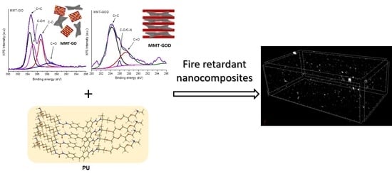
X-ray photoelectron spectrometry is well-known to be among the most powerful tools to determine the structures of carbon-based materials; thus, the C1s level was deconvoluted into secondary peaks to assess structural modification of nanohybrids through functionalization. The high-resolution C1s spectrum registered for GO (
Figure 2a) typically exhibits the following bands: C=C (at 284.78 eV), C-O-C (at 286.11 eV) and O-C=O (at 288.82 eV) and π–π* electronic transitions (at 291.43 eV). Meanwhile, in the case of GOD (
Figure 2b), although similar components are found, the peak corresponding to C-O-C (at 286.51 eV) is observed to overlap with the one corresponding to the C-N species. When MMT- and GO-based nanohybrids are analyzed, there are several differences: in the case of MMT–GO (
Figure 2c), the peak assigned to C- is more significantly related to the other secondary peaks, and this is an indicator of the presence of GO at the MMT surface [
23]; meanwhile, for MMT–GOD (
Figure 2d), besides the lower amount of carbon content (shown in
Table 2), it can be seen that the C-O/C-N secondary peak is less significant, proving that the cationic exchange process occurred between MMT and GOD. Thus, most of the GOD molecules are located now within the MMT layers.
When looking at the surface elemental composition extracted from the survey XPS spectra (
Table 2), it can be observed that the C1s percent is an indicator of surface modification. In comparison with GO, when functionalization was performed on GOD, the value of the C1s content is decreased, due to the presence of amine groups at the surface. Although the MMT structure shows adventitious carbon content [
24], for MMT–GO nanohybrids, a 14.87 at.% C suggests that a part of the GO exists on the MMT surface. However, in the case of MMT–GOD, the clay layers were intercalated with GOD, which manages to penetrate within the MMT layers due to the higher compatibility offered by GO functionalization with D230; this hypothesis is sustained by the reduced C1s content at the surface compared with the MMT–GO nanohybrids.
The thermal degradation of nanoreinforcing agents through TGA revealed an efficient quantification for the functionalization stages starting with GO and MMT as raw materials: for the clay, we noticed its high thermal stability with a single-step degradation; meanwhile, for GO, the thermograms show a rapid degradation, which begins at 330 °C, caused by the decomposition of its surface oxygenated moieties, leading to a lower char amount. The TGA curve for GOD presents a different trend, due to the newly attached functional groups, leading also to an increase in the char content compared with neat GO (
Table 3). In the case of nanohybrid structures, the thermal behavior of GO and GOD layers was masked by the good thermal stability of MMT. Their curves show similar shapes, as can be observed from
Figure 3.
For a better understanding of the modification process regarding the displacement of the sheets within nanohybrid formation, XRD analysis was performed on the GO, GOD, MMT and resulting MMT–GO and MMT–GOD structures (
Figure 4). In the Bragg equation (2d sinθ = nλ), if 2θ is lower, the spacing of the nanosheets is larger.
For MMT nanohybrid structures, all the characteristic signals of MMT are present in the X-ray diffraction patterns; however, there are two peaks that need to be considered. It can be seen that there is a shift in the case of the first-order d-spacing peak d (001) reflection that is characteristic for MMT from 2θ of 6.29° to a lower 2θ of 5.74° for MMT–GO and 6.07° for MMT–GOD. When nanohybrids were analyzed, we noted that the characteristic peak remained and only slightly shifted a to lower angle; in addition, its shape became broader with decreased intensity, indicating that the effects between MMT and GO did not change the original layered structure of MMT. Moreover, the shift indicates an increase in the interlayer distance within the crystalline structure of the clay lamellae when functionalization with graphene oxide was realized [
25,
26]. This is an indicator that the GO was successfully intercalated between MMT platelets [
23].
The diffraction peak at 2θ = 26.43° with an inter-planar distance of 3.6 nm in the spectrum of graphene oxide indicates exfoliated graphene nanosheets separated in the form of a few-layered structure [
27]. The decrease of 2θ at 23.88° for GOD suggests a higher distance between the graphene sheets after the amine functionalization reaction [
28,
29].
The characteristic 2θ peaks at 24.14° and 23.88° for the GO and GOD structure, respectively, are not translated into the nanohybrid diffractograms, accordingly showing that these structures are altered by the interaction with MMT. However, it can be seen that MMT–GO and MMT–GOD nanohybrids are keeping, with lower intensity and slightly shifted, the characteristic 002, 110 and 013 reflection features from the layered clay structure. This is an indicator that MMT layers are connected with GO sheets through weak interactions.
3.2. Composite Materials Characterization
The chemical structure of the polyurea was characterized and confirmed by using FTIR analysis, and the spectra are shown in
Figure 5.
The isocyanate crosslinker showed a specific strong band at 2266 cm−1, correlated with the N=C=O asymmetric stretch, which is consumed during the reaction of polyurea formation, as it can be observed from the PU spectrum. The signal at 1521 cm−1 was ascribed to the NO2 antisymmetric vibration, and the peak at 1718 cm−1 corresponds with the carbonyl C=O group.
The functional groups in the final product were identified as follows: the urea functional group was confirmed according to the peaks at 1600 cm
−1 (C=O stretching vibration), 1511 cm
−1 (N-H bending vibration), 2867 cm
−1 (C-H stretching vibrations) and 3330 cm
−1 (characteristic stretching vibration for N-H in the urea functional group) [
30,
31].
The peaks at 1662 cm
−1 indicates the hydrogen bonding formed by one C=O of the urea groups with two nearby N-H. This interaction is conventionally called “disordered” bonding. The strong absorption peak at 1100 cm
−1 is attributed to the isocyanate C-N stretch, while the C-O stretching vibration is represented by the presence of the signals at 1304 cm
−1, 1235 cm
−1 and 945 cm
−1. The spectra also show a sharp peak at 1540 cm
−1, revealing the presence of nitro compounds NO
2 [
32].
The polyurea matrix exhibits a combination of elastic and viscous properties that can be explained in standard engineering terms, using DMA methods. It can be seen from
Figure 6, that ε exhibited a quasilinear stability with the temperature in the glassy state and dropped rapidly due to the changes which occur as a result of intramolecular friction when passing to rubbery state [
33].
By analyzing the storage modulus curves, it can be noticed that the PUM, PUG and PUGD samples have slightly lower values in the glassy state for ε’ when compared with the PU matrix, due to the presence of the reinforcing agent that interfered and disrupted the hard segment content that is responsible for the mechanical properties [
34], inducing rigidity throughout its inorganic structure. When PUMGD nanocomposites are analyzed, only a slight increase is observed as compared with neat matrix.
In the case of the PUMG samples, the storage modulus curves indicate a superior elastic response by increased values of ε’ when compared with the PU matrix within the glassy state; this result may be a consequence of the synergistic interaction of the nanostructures with the polymeric matrix, proving that a good dispersion and strong interfacial interaction between the nanofiller and the polymeric matrix occurred. At the same time, the functional groups from the GO surface can interact with the amide groups from the polyurea molecules, playing a key role in the formation of nanoscale rigid domains, thus leading to the formation of an ideal crystalline phase/amorphous phase ratio in the final composite materials [
35,
36].
The DSC data revealed that the samples subjected to analysis had two characteristic Tg temperatures (
Table 4). The first corresponds to the soft areas and provides information on the elasticity of the samples, and the second temperature corresponds to the hard areas and is responsible for the stiffness of the synthesized material. The two values indicate the micro-phase separation morphology of the material [
37,
38,
39]. As shown in
Table 4, the best elastic behavior is represented by the PUG sample, due to the insertion of large flexible GO sheets; meanwhile, in terms of rigidity, the PUGD sample is noted to have the highest Tg of hard domains. In an overall look through the Tg values of nanocomposite samples, one can observe that the values for soft domains are particularly influenced by the structure of the reinforcing agents. Thus, a low Tg for PUG could have come from large GO sheets, but, at the same time, a second hypothesis can be that the reactants were hindered to reach active sites by aggregates; therefore, elastic behavior is enhanced by excess. However, when functionalized GO is used as a reinforcing agent, the value of soft Tg is higher, due to the fact that lower dimensions of GOD aggregates or functionalization of the GO can possibly increase the crosslinking density through participation in the polyurea formation of the amine groups from the D230 molecule. In the case of MMT nanostructures, the first pattern mentioned above is also observed. Possible agglomeration of MMT nanoclay lead to decreased values for Tg. However, the addition of GO sheets to MMT clay modified the nanostructures dimensions and, thus, their distribution within the polyurea network. The soft regions of PUMG and PUMGD have similar values for Tg. The main difference between these two samples resides in the hard region, where PUMGD shows a higher value for Tg.
The thermal properties were assessed by using thermogravimetric analysis (TGA) to obtain the thermal stability of the newly synthesized materials in inert (N2) and oxidative (Air) atmospheres (
Figure 7 and
Table 5). Upon exceeding a temperature threshold, a thermo-oxidative process occurred between 290 and 330 °C. The result of this process, which started with breaking the chemical bonds in the PU matrix chain, was the release of some volatile products, thus leading to the decrease of the initial mass of the analyzed sample.
Regarding this aspect, in a degradation study realized by Awad and Wilkie, carbon dioxide was found to be preponderant in the first stage of degradation, while, in the second stage, isocyanate end groups (i.e., HNCO and CH3NCO, respectively) and hydrocarbon fragments CxHy were predominant [
39]. In this study, this oxidative process was not significantly influenced by the presence of the reinforcing agent, probably due to its low amount. However, an increase in thermal stability was observed in the case of PUMGD, and this outcome can be connected to the hypothesis of amine involvement in the PU-formation reaction. In this case, a higher crosslinking density can hinder the bond scission propagation throughout the sample network. At the same time, the lower Td5% values obtained for the nanocomposites reinforced with nanohybrid structures can be explained by the fact that a large number of centers that are susceptible to inducing accelerated decomposition were introduced by the aggregates formed between the clay layers and GO sheets. The presence of MMT does not influence the decomposition process, because the inorganic material is highly thermally stable.
The thermal degradation of PU and its nanocomposites was evaluated by TGA, and the results are shown in
Figure 7 and
Table 5, respectively. As it can be seen, under a nitrogen atmosphere (
Figure 7a,b), the PU and its nanocomposites present two degradation stages at 280–330 °C and 330–453 °C. The first step of thermal degradation occurs due to the degradation of the hard segments of urea groups which have lower thermal stability. The second stage is assigned to the soft segments which are generated by the long polyether amine chains and possess higher thermal stability [
40]. However, in the case of TGA analysis under air atmosphere (
Figure 7c,d), one more decomposition peak occurs in the temperature range of 480–600 °C, as compared with that under nitrogen atmosphere. This step can be attributed to the thermo-oxidative degradation of the polymeric residue [
41].
The fracture characteristic morphology shown by the SEM images (
Figure 8) revealed that the introduction of the nanoreinforcing agent disrupted the PU network arrangement. This disruption can be better observed in the case of PUMG (
Figure 8d), where a smooth surface was obtained. At the same time, surface compatibility between nanoreinforcing agent and polyurea matrix can be ascribed to the roughness of the fracture surface. Thus, one can observe an efficient embedding of the reinforcing agent within the PU matrix. However, PUG and PUM (
Figure 8b,c) still have some wiggles, which can indicate GO and MMT pull-out at fracture.
Micro-computed tomography (micro-CT) was used for the visualization and quantification of the nanoreinforcing agent into the polyurea matrix. For the PUMGD composite specimen (
Figure 9), one rectangular volume of interest (VOI) dataset was extracted. The VOI was constrained in terms of volume and height to a mass at a maximum of 99% of the scanned specimen. In CTAn, the VOI was processed through a common procedure consisting of thresholding, which was performed to clear-cut the sample’s inorganic phase from the polymer matrix; despeckling, which was used for the removal of residual scanning artefacts; and 3D analysis, which was conducted to quantify the specific surface (total clay surface/volume ratio) of MMT–GOD agglomerates, total volume of the filler and structure thickness, a granulometric measure of the clay distribution within the matrix. Reconstructed tomograms are grayscale images, with a gray palette covering 0 (black) to 255 (white). For organic matrices reinforced with inorganic nanoparticles, thresholding was carried out with ease, as the difference in X-ray attenuation coefficient is high; hence, the clays are depicted in light gray tones. Post-thresholding, the quantitative 3D analysis was carried out.
Some studies state that polyurea has an ideal morphology for mechanical properties [
42]. Mott and et al. pointed out in their study that the response of polyurea to mechanical perturbation is strongly rate-dependent and associated with substantial energy loss [
43].
The mechanical properties of polyurea are also influenced by hydrogen bonds. High mechanical toughness is a result of the extensive intermolecular hydrogen bonding in polyurea hard domains [
38]. Many studies have demonstrated the influence and behavior of these bonds during stress and deformation. In the case of nanocomposites, the molecular weights of polyurea, the dispersion of nanostructure and the hydrogen bonds formed with the polyurea matrix are the three decisive factors for the mechanical strength. Qian et al. reported that the low addition of graphene oxide (0.2 wt%) substantially increased the tensile strength and elongation of polyurea, but the overloading of graphene oxide affected the polymerization of polyurea [
35].
The stress–strain result shows that the polyurea samples have different behaviors, ranging from a highly deformable soft rubber to a rigid, brittle material when subjected to mechanical stress, as shown in
Table 6. In comparison with the neat PU sample, the most significant increase in the Young’s modulus values can be noticed for the PUMG sample. The reduced values of the Young’s modulus of the PUMGD can be related to the formation of complex networks between the nanostructures used as reinforcing agents and the matrix, leading to the plasticization given by the unreacted amine. In the case of PUM, structural compatibility issues could lead to agglomerated MMT layers, which could hinder the mobility of polyurea reactants. The stiffest nanocomposite according to the values for the Young’s modulus is the PUMG sample. This aspect confirms that the reinforcing agent used in this case has a more agglomerated structure embedded within the polymeric matrix, contributing to the mechanical properties of the final material, in accordance with DMA storage modulus curves.
As overall mechanical properties, the MMT- and MMT–GOD-reinforcing agents interfere in the structural organization of the polymeric matrix and lower the mechanical properties. Meanwhile, for the GO-reinforced polyurea sample, the higher value for the tensile stress comes from the ability of the graphene oxide nanosheet to provide flexibility to the system by unfolding when nanocomposites are subjected to load [
44].
The flame-retardancy behavior of polyurea samples was assessed by using limiting-oxygen-index (LOI) experiments, and the results are summarized in
Table 7. According to the ASTMD 2863-97 standard, a material in which the LOI value is above 23 ± 2% is rated as flame retardant. Compared with the neat polyurea sample, a slight increase in the value of LOI can be seen in the case of nanocomposite samples reinforced with graphene and montmorillonite. This may be due to the formation of a barrier at the material surface that limits the oxygen permeability into the material and the evaporation of volatile compounds and prevents the heat transfer. The most significant values for LOI can be noticed in the case of PUMG and PUMGD samples for which GO and MMT may exhibit a synergistic effect towards the flame retardancy of the nanocomposites [
44]. This statement is also supported by TGA results in which the value for the char residue is correlated with the LOI, which assesses high thermal stability. The literature data for PU-based materials showed that carbon dioxide is mainly released after decomposition [
45].


 ,
, 


