Abstract
Thermal signature reduction in camouflage textiles is a vital requirement to protect soldiers from detection by thermal imaging equipment in low-light conditions. Thermal signature reduction can be achieved by decreasing the surface temperature of the subject by using a low thermally conductive material, such as polycarbonate, which contains bisphenol A. Polycarbonate is a hard type of plastic that generally ends up in dumps and landfills. Accordingly, there is a large amount of polycarbonate waste that needs to be managed to reduce its drawbacks to the environment. Polycarbonate waste has great potential to be used as a material for recycled fibre by the melt spinning method. In this research, polycarbonate roofing-sheet waste was extruded using a 2 mm diameter of spinnerette and a 14 mm barrel diameter in a 265 °C temperature process by using a lab-scale melt spinning machine at various plunger and take-up speeds. The fibres were then inserted into 1 × 1 rib-stitch knitted fabric made by Nm 15 polyacrylic commercial yarns, which were manufactured by a flat knitting machine. The results showed that applying recycled polycarbonate fibre as a fibre insertion in polyacrylic knitted fabric reduced the emitted infrared and thermal signature of the fabric.
1. Introduction
Heat migrates from hotter areas to cooler areas through thermal convection, thermal conduction, and thermal radiation [1]. This phenomenon is applied in every aspect of our daily lives, from the most simple parts of our routine to the most sophisticated military applications. The combination of heat migration from an object to the environment can create a thermal signature, measured by thermal imaging techniques [2]. Thermal signature is affected by the temperature of the object and background, and an effective way to reduce it is by reducing the emissivity [3,4]. The temperature difference (ΔT) between the object and background affects the thermal region in thermal imaging [5,6]. Thermal imaging is proven to produce an advanced spectral range that can be seen by a human and shows an obvious contrast between the environment and objects of high-temperature variance [7,8,9,10,11]. Currently, thermal imaging techniques are used incommercial activities, industrial processes and by the military. The military is one area that develops camouflage textiles to protect a soldier from detection by various equipment in many operations, including surveillance purposes at night or in low-light conditions [4]. Generally, there are several polymers used in camouflage textile materials because of their capability to minimize infrared visual detection by reducing the thermal signature of the soldier, one of them is polycarbonate.
Polycarbonate polymer was developed in 1953; it is tough, rigid, and has a relatively high melting temperature, from 225 °C to 250 °C, with a glass transition temperature of 145 °C. It also has flame retardant property, with an oxygen index of 26, in addition to thermal and electrical insulation [12]. Polycarbonate is made from a condensation reaction of bisphenol A with phosphorus (phosgene) in alkaline media [13]. The presence of bisphenol A makes polycarbonate capable of absorbing infrared, which can be utilized for military textile applications [13,14]. Due to the optical and mechanical properties of polycarbonate, Fujitsu developed and introduced polycarbonate optical fibre in 1986 [15]. Polycarbonate fibre was developing rapidly, particularly for high-temperature resistant polymer sensor applications, since it has a high glass transition temperature and high flexibility for bending. Since that time, polycarbonate fibre also started to develop rapidly in various applications such as high-temperature-resistant polycarbonate fibre, electrical conductive polycarbonate fibre (by adding multiwalled carbon nanotubes), and strain sensing polycarbonate fibre [15,16,17]. However, all of the existing polycarbonate fibres are developed from virgin polycarbonate material instead of waste polycarbonate material.
The global polycarbonate market significantly increased from 2000 to 2010, and it is forecasted to increase to 5.5 million tons by 2024, due to the high demand in the electrical, electronics, and automotive industries [13,18,19]. Polycarbonate is a hard type of plastic that is not easily recycled and polycarbonate waste generally ends up in dumps and landfills [20]. Accordingly, there is a huge amount of polycarbonate waste available which needs to be managed to reduce its drawbacks to the environment. Therefore, the fabrication of polycarbonate sheet waste for thermal signature reduction application is quite promising, particularly for incorporating microstructures into apparel for visible and infrared camouflage used in the military [21].
2. Materials and Methods
All of the polycarbonate fibres in this research were produced from multiwall polycarbonate roofing-sheet waste (grey colour, 5 mm thickness, from Twinlite, PT Impack Pratama, Jakarta, Indonesia). To identify and confirm the material, material characterization was conducted using an FTIR-8400 (Shimadzu, Kyoto, Japan). To produce recycled polycarbonate fibres, polycarbonate roofing-sheet waste was cleaned before the grinding process. The ground polycarbonate chips were then extruded using a 2 mm diameter of spinnerette and a 14 mm barrel diameter in a 265 °C temperature process, using a lab-scale melt spinning machine as can be seen in Figure 1. Variations in two processing parameters were applied to produce several polycarbonate fibre properties, plunger speed (0.10, 0.15 and 0.18 cm/s) and take-up speed (6.2, 6.9 and 9.2 m/min). The recycled polycarbonate fibres that were produced were then inserted into 1 × 1 rib-stitch knitted fabric made by Nm 15 polyacrylic commercial yarns, which were manufactured by a flat knitting machine with a fabric construction of 15 courses per inch and 18 wales per inch.
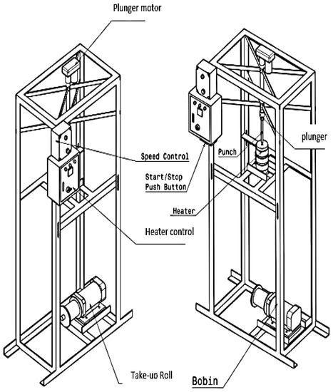
Figure 1.
Schematic diagram of lab-scale melt spinning machine.
The fibre diameter measurement was performed using an Olympus CX-22 binocular microscope (Tokyo, Japan) assisted camera adapter, the fibre tensile strength and elongation were measured using an Instron tensile testing machine according to ASTM D 3822-07, the fabric area density was measured according to SNI-ISO 3801:2010, and the fabric bursting test was measured according to SNI 0561:2008. To demonstrate the thermal signature reduction in fabrics, we first covered the heat source (40 °C, 68 °C and 100 °C) with the various polycarbonate–polyacrylic fabrics, the fabric surface temperature and the thermal signature of each fabric was then captured using a Flir One thermal imaging camera (Teledyne FLIR LLC, Wilsonville, OR, USA), which can measure temperatures from −20 °C to 200 °C (2% instrumental error). To achieve a high accuracy result, the ambient temperature was maintained between 30 °C and 45 °C, and the measurement distance was 0.8 m [22,23]. The surface temperature reduction in each fabric was calculated to discover the emissivity decrement and confirmed the thermal signature reduction effect.
3. Results and Discussion
3.1. Fabrication of Polyacrylic–Polycarbonate Fabric
The FTIR spectrum of polycarbonate sheet waste is shown in Figure 2. Polycarbonate has principal peaks around 1015 cm−1 caused by symmetric O–C–O carbonate group deformations, CH3-vibrations around 1081 cm−1, C=C-vibrations at 1506 cm−1, C=O carbonate group deformations near 1775 cm−1 and peaks around 3.000 cm−1 caused by C–H aromatic ring deformations. The result of the characterization confirmed that the polymer of this material was polycarbonate.
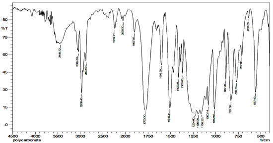
Figure 2.
IR absorption spectrum of multiwall roofing-sheet waste.
Figure 3b–d show the several variations of fabric produced in this research, all of these variations were used in a 1 × 1 rib-stitch knit due to its structural dimension stability and extensive shrinkage in width [24]. To demonstrate the thermal signature reduction ability of the recycled polycarbonate fibre, we prepared three variations of polycarbonate composition in knitted fabric by inserting recycled polycarbonate fibres in polyacrylic knitted fabric. We prepared fabrics containing 0% polycarbonate–100% polyacrylic fabric (without polycarbonate fibre insertion); 50% polycarbonate–50% polyacrylic (with one strand of polycarbonate fibre insertion) and 66.7% polycarbonate–33.3% polyacrylic (with two strands of polycarbonate fibre insertion). This variation was the best option considering the structure of the 1 × 1 rib-stitch fabric construction and the fluency of the knitting process in knitted fabric fabrication, according to a preliminary research result. The amount of recycled polycarbonate fibre insertion influenced the fabrication process, excessive recycled polycarbonate fibre insertion caused a jam of the yarn feeding, whereas inadequate recycled polycarbonate fibre insertion may cause loose and stray fibre in the fabric due to improper yarn tension.
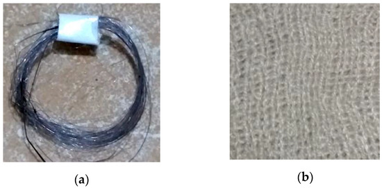
Figure 3.
(a) Recyled polycarbonate fibre; (b) 0% Polycarbonate–100% Polyacrylic fabric; (c) 50% Polycarbonate–50% Polyacrylic; (d) 66.7% Polycarbonate–33.3% Polyacrylic.
3.2. Fibre Diameter
In the second part of the study, we examined the correlation of plunger speed and take-up speed with the recycled polycarbonate fibre diameter. Considering the available machine settings, we used five variations of processing parameters; the highest plunger speed was 0.18 m/min and the lowest plunger speed was 0.10 m/min, whereas the highest take-up speed was 9.2 cm/min and the lowest plunger speed was 6.9 cm/min. We determined that a high take-up speed resulted in a finer fibre diameter than a low take-up speed. Meanwhile, a low plunger speed produced a coarser fibre diameter than a fast plunger speed. This occurred because of the strain rate along the spin line [25]. Higher take-up speed leads to a higher strain rate, but otherwise higher plunger speed leads to a lower strain rate.
Figure 4 shows the finest fibre diameter in this study was produced by setting the plunger speed at 0.10 m/min and the take-up speed at 9.2 cm/min, whereas the coarsest fibre diameter was produced by setting the plunger speed at 0.18 m/min and the take-up speed at 6.9 cm/min. This occurred because a high take-up speed leads to a rapid decrease in the fibre diameter [26].
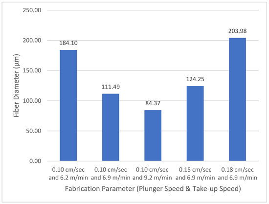
Figure 4.
Correlation of plunger speed and take-up speed with polycarbonate fibre diameter.
3.3. Fibre Tenacity
Fibre tenacity has an inversely proportional value to fibre diameter, a fine diameter of fibre leads to higher fibre tenacity, since an increase in the strain rate creates a better molecular chain orientation and alignment. An increase in molecular chain alignment leads to an increase in tenacity because the molecular chains become tighter, as shown in Figure 5 [27,28]. Figure 6 shows that the tenacity of fibre produced from the combination of the highest take-up speed and lowest plunger speed was 1.69 g/denier. The combination of the highest take-up speed and lowest plunger speed creates the highest strain rate, which leads to improvement of polymer molecular orientation degree. The improvement of polymer molecular orientation degree results in the increase in fibre tenacity.
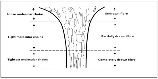
Figure 5.
Change of molecular orientation in the take-up process.
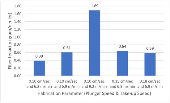
Figure 6.
Correlation of plunger speed and take-up speed with polycarbonate fibre tenacity.
3.4. Fabric Areal Density
Fabric areal density is a measurement of mass per unit area of the fabric, it is affected by course per inch, wale per inch, yarn count, material insertion, and other knit structures that influence physical properties, such as shrinkage, water absorbency, and air permeability [29]. As can be seen in Figure 7, the 66.7% polycarbonate–33.3% polyacrylic fabric has the highest areal density, meanwhile, the 0% polycarbonate–100% polyacrylic fabric has the lowest areal density. This occurs because the 66.7% polycarbonate–33.3% polyacrylic fabric has two strands of recycled polycarbonate fibre insertion in every course, and this will improve fabric mass. Improvement of fabric mass affects the fabric’s physical properties, which is very important, especially for protective garments [30].
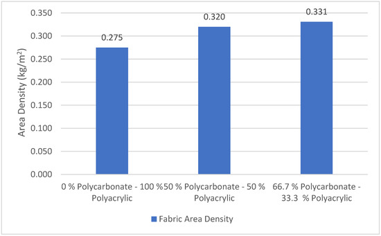
Figure 7.
The areal density of polycarbonate–polyacrylic fabrics.
We determined that the 0% polycarbonate–100% polyacrylic fabric has the lowest areal density, more than 20% lighter than the areal density of the 66.7% polycarbonate–33.3% polyacrylic fabric. This may lead to poor cover opacity and bursting strength [31]. For some applications, lightweight knitted fabric such as the 0% polycarbonate–100% polyacrylic is preferred over other types of clothing [32].
3.5. Bursting Strength
There are several important mechanical properties in fabric, one of them is bursting strength, which is generally associated with knitted fabrics, or breaking strength with woven fabrics [33,34]. Figure 8 shows that the 66.7% polycarbonate–33.3% polyacrylic fabric has a higher bursting strength compared with the 0% polycarbonate–100% polyacrylic fabric and the 50% polycarbonate–50% polyacrylic fabric. The bursting strength of the 66.7% polycarbonate–33.3% polyacrylic fabric was 25% higher than the 0% polycarbonate–100% polyacrylic fabric. This occurred because the 66.7% polycarbonate–33.3% polyacrylic fabric has recycled polycarbonate fibre insertion that absorbs external force during the bursting strength test. A high tightness factor and high areal density of the fabric structure leads to a high bursting strength [35]. According to this study, we found that the insertion of recycled polycarbonate fibres can improve the mechanical properties of a knit-fabric and that this is suitable for a high-performance textile application.
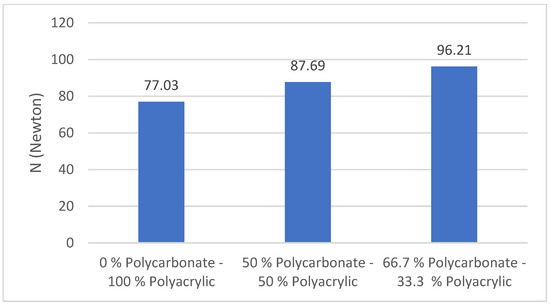
Figure 8.
Bursting strength of polycarbonate–polyacrylic fabrics.
3.6. Thermal Signature Reduction
A thermal signature is created through an apparent temperature differential between an object and its background [6]. Thermal signature is one of the most critical aspects to prevent or delay detection in low-light military camouflage operations. Military camouflage has at least two requirements that need to be managed; the near-infrared and the visible regions of the spectrum [36]. Temperature regulation is required for reducing the emitted infrared waves in military camouflage, lower emitted infrared waves lead to higher thermal insulation properties [37]. Therefore, it is important to select a material that has a low infrared emittance and high thermal insulation to reduce the thermal signature of camouflage textile.
Figure 9a–c show the thermal signatures of knitted fabrics for three different recycled polycarbonate fibre contents using a 40 °C heat source. Figure 9c, showing the fabric with the highest recycled polycarbonate content (67.7%), has a darker thermal signature compared with Figure 9b,c, which have lower recycled polycarbonate contents. The result was similar when the temperature of the heat source was increased, Figure 9d–f are the thermal signatures of knitted fabrics with various recycled polycarbonate fibre contents using a 68 °C heat source. The thermal signature of the knitted fabric in Figure 9d, which had the lowest recycled polycarbonate fibre content (0%), is brighter than that of the other knitted fabrics, which had a higher recycled polycarbonate content. The thermal signatures of the knitted fabrics on a 100 °C heat source are shown in Figure 9g–i. The knitted fabrics which had a higher recycled polycarbonate content produced darker thermal signatures, as shown by Figure 9i,j, which had 67% and 50% recycled polycarbonate content. Figure 9a–g have no recycled polycarbonate fibre insertion and all show brighter thermal signatures compared with the other fabric variations, especially Figure 9c,f,i, which had the highest amount of polycarbonate fibre insertion. It was found that applying recycled polycarbonate fibres as an insertion in polyacrylic knitted fabrics reduced the emitted infrared waves captured by a thermal imaging camera.
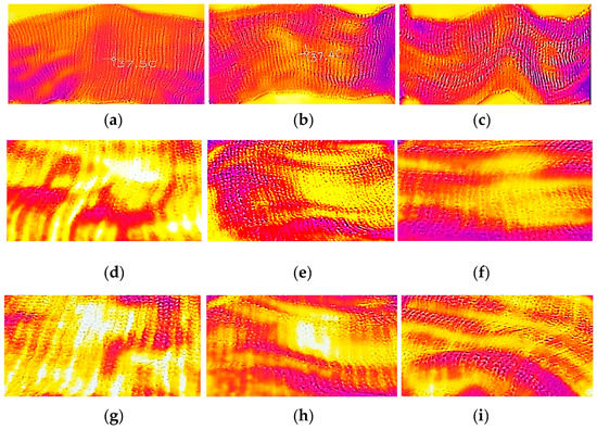
Figure 9.
Thermography of knitted fabric: (a) 0% Polycarbonate–100% Polyacrylic on 40 °C; (b) 50% Polycarbonate–50% Polyacrylic on 40 °C; (c) 66.7% Polycarbonate–33.3% Polyacrylic on 40 °C; (d) 0% Polycarbonate–100% Polyacrylic on 68 °C; (e) 50% Polycarbonate–50% Polyacrylic on 68 °C; (f) 66.7% Polycarbonate–33.3% Polyacrylic on 68 °C; (g) 0% Polycarbonate–100% Polyacrylic on 100 °C; (h) 50% Polycarbonate–50% Polyacrylic on 100 °C; (i) 66.7% Polycarbonate–33.3% Polyacrylic on 100 °C.
Thermal signature reduction in infrared camouflage is reached by managing the surface temperature and the surface emittance of the object [38]. Decreasing the surface temperature of the object represents a reduction in the surface emittance and thermal signature. Figure 10 shows that the 66.7% polycarbonate–33.3% polyacrylic fabric has the highest surface temperature reduction in all heat source temperatures. At high operational temperature (100 °C), the surface temperature reduction in the 66.7% polycarbonate–33.3% polyacrylic fabric is almost 75% higher than the 0% polycarbonate–100% polyacrylic fabric. The effect is quite similar at other operational temperatures, for 40 °C and 68 °C heat source temperatures, the surface temperature reduction in the 66.7% polycarbonate–33.3% polyacrylic fabric is 27.6%, and 70.1% higher than the 0% polycarbonate–100% polyacrylic fabric. This is caused by the use of recycled polycarbonate fibre as an insertion in polyacrylic knitted fabric, since polycarbonate has a low thermal conductivity of 200 mW/m*K compared with polyacrylic yarn which has 310 mW/m*K of thermal conductivity [39,40]. The most substantial differences can be observed using a heat source temperature of 100 °C, where the knitted fabric thermal insulation is increased to 74.5% in the 66.7% polycarbonate–33.3% polyacrylic fabric. A higher operational temperature will lead to a higher thermal insulation difference. The thermal insulation of the fabric is proportional to operational temperature because thermal conductivity is dependent on temperature [39].
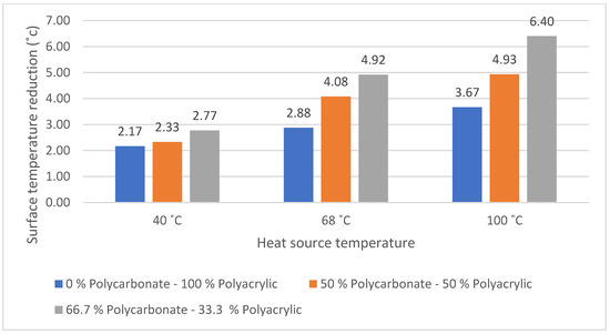
Figure 10.
Surface temperature reduction in various polycarbonate-content fabrics.
The surface temperature reduction is directly proportional to the recycled polycarbonate fibre content, higher recycled polycarbonate fibre content leads to the increases in surface temperature reduction. This result confirms the advantage of applying recycled polycarbonate fibre to reduce the surface temperature and thermal signature of the fabric.
4. Conclusions
This research produced and evaluated recycled polycarbonate fibre from multiwall polycarbonate roofing-sheet waste. It was found that multiwall polycarbonate roofing-sheet waste was a potential material for synthetic fibres due to its spinnability. High take-up speeds produced fine fibres, whereas high plunger speeds lead to lower strain rates and created coarse fibrea. The coarsest fibre diameter in this study was produced by setting the plunger speed at 0.18 m/min and the take-up speed at 6.9 cm/min, whereas the finest fibre diameter was produced by setting the plunger speed at 0.10 m/min and the take-up speed in 9.2 cm/min; this setting also produced the highest fibre tenacity of 1.69 g/denier. The take-up speed value was proportionally linear to the resulting tenacity of fibre.
The insertion of recycled polycarbonate fibre can improve the mechanical properties of knitted fabrics and it is suitable for high-performance textile applications, the bursting strength of the 66.7% polycarbonate–33.3% polyacrylic fabric was 25% higher than the 0% polycarbonate–100% polyacrylic fabric. The fabric which had a higher recycled polycarbonate fibre content had a higher surface temperature and thermal signature reduction at all temperatures. The surface temperature reduction in the 66.7% polycarbonate–33.3% polyacrylic fabric was almost 75% higher than the 0% polycarbonate–100% polyacrylic fabric. We found that applying recycled polycarbonate fibres as a fibre insertion in polyacrylic knitted fabrics reduced the emitted infrared waves captured by a thermal imaging camera.
Author Contributions
Conceptualization, A.S.; methodology, A.S, A.F., H.T., P.D. and I.T.; formal analysis, A.S, A.F., H.T., P.D. and I.T.; investigation, A.S, A.F., H.T., P.D. and I.T.; data curation, A.F., H.T., P.D. and I.T.; writing—original draft preparation, A.S. and A.U.R.; writing—review and editing, A.S., A.U.R., N. and B.Y.; supervision, N. and B.Y.; project administration, A.F., H.T., P.D. and I.T. All authors have read and agreed to the published version of the manuscript.
Funding
This research was funded by BPSDMI—Kementerian Perindustrian Republik Indonesia.
Acknowledgments
The technical support provided by PT Superbtex Spinning Mill, Bandung, Indonesia.
Conflicts of Interest
The authors declare no conflict of interest.
References
- Dai, G.; Shang, J.; Huang, J. Theory of Transformation Thermal Convection for Creeping Flow in Porous Media: Cloaking, Concentrating, and Camouflage. Phys. Rev. E 2018, 97, 022129. [Google Scholar] [CrossRef] [PubMed]
- Negied, N.K.A.-W.; Hemayed, E.B.; Fayek, M. HSBS: A Human’s Heat Signature and Background Subtraction Hybrid Approach for Crowd Counting and Analysis. Int. J. Pattern Recognit. Artif. Intell. 2016, 30, 1655025. [Google Scholar] [CrossRef]
- Dev, O.; Dayal, S.; Dubey, A.; Abbas, S.M. Multi-Layered Textile Structure for Thermal Signature Suppression of Ground Based Targets. Infrared Phys. Technol. 2020, 105, 103175. [Google Scholar] [CrossRef]
- Rubežienė, V.; Padleckienė, I.; Žuravliova, S.V.; Baltušnikaitė, J. Reduction of Thermal Signature Using Fabrics with Conductive Additives. Mater. Sci. 2013, 19, 409–414. [Google Scholar] [CrossRef]
- Hixson, J.G.; Jacobs, E.L.; Vollmerhausen, R.H. Target Detection Cycle Criteria When Using the Targeting Task Performance Metric; Driggers, R.G., Huckridge, D.A., Eds.; International Society for Optics and Photonics: London, UK, 2004; p. 275. [Google Scholar]
- Holst, G.C. Common Sense Approach to Thermal Imaging; SPIE: Bellingham, WA, USA, 2000; ISBN 978-0-8194-3722-8. [Google Scholar]
- Liu, Q.; Zhuang, J.; Ma, J. Robust and Fast Pedestrian Detection Method for Far-Infrared Automotive Driving Assistance Systems. Infrared Phys. Technol. 2013, 60, 288–299. [Google Scholar] [CrossRef]
- Bertozzi, M.; Broggi, A.; Caraffi, C.; Del Rose, M.; Felisa, M.; Vezzoni, G. Pedestrian Detection by Means of Far-Infrared Stereo Vision. Comput. Vis. Image Underst. 2007, 106, 194–204. [Google Scholar] [CrossRef]
- Fang, Y.; Yamada, K.; Ninomiya, Y.; Horn, B.K.P.; Masaki, I. A Shape-Independent Method for Pedestrian Detection with Far-Infrared Images. IEEE Trans. Veh. Technol. 2004, 53, 1679–1697. [Google Scholar] [CrossRef]
- Li, J.; Gong, W.; Li, W.; Liu, X. Robust Pedestrian Detection in Thermal Infrared Imagery Using the Wavelet Transform. Infrared Phys. Technol. 2010, 53, 267–273. [Google Scholar] [CrossRef]
- Olmeda, D.; de la Escalera, A.; Armingol, J.M. Contrast Invariant Features for Human Detection in Far Infrared Images. In Proceedings of the 2012 IEEE Intelligent Vehicles Symposium, Alcal de Henares, Madrid, Spain, 3–7 June 2012; IEEE: Alcal de Henares, Madrid, Spain, 2012; pp. 117–122. [Google Scholar]
- Kyriacos, D. Polycarbonates. In Brydson’s Plastics Materials; Elsevier: Amsterdam, The Netherlands, 2017; pp. 457–485. ISBN 978-0-323-35824-8. [Google Scholar]
- Muhamad, M.S.; Salim, M.R.; Lau, W.J.; Yusop, Z. A Review on Bisphenol a Occurrences, Health Effects and Treatment Process via Membrane Technology for Drinking Water. Environ. Sci. Pollut. Res. 2016, 23, 11549–11567. [Google Scholar] [CrossRef]
- Kraus, R.G.; Emmons, E.D.; Thompson, J.S.; Covington, A.M. Infrared Absorption Spectroscopy of Polycarbonate at High Pressure. J. Polym. Sci. Part B Polym. Phys. 2008, 46, 734–742. [Google Scholar] [CrossRef]
- Fasano, A.; Woyessa, G.; Stajanca, P.; Markos, C.; Stefani, A.; Nielsen, K.; Rasmussen, H.K.; Krebber, K.; Bang, O. Fabrication and Characterization of Polycarbonate Microstructured Polymer Optical Fibers for High-Temperature-Resistant Fiber Bragg Grating Strain Sensors. Opt. Mater. Express 2016, 6, 649. [Google Scholar] [CrossRef]
- Pötschke, P.; Brünig, H.; Janke, A.; Fischer, D.; Jehnichen, D. Orientation of Multiwalled Carbon Nanotubes in Composites with Polycarbonate by Melt Spinning. Polymer 2005, 46, 10355–10363. [Google Scholar] [CrossRef]
- Bautista-Quijano, J.R.; Pötschke, P.; Brünig, H.; Heinrich, G. Strain Sensing, Electrical and Mechanical Properties of Polycarbonate/Multiwall Carbon Nanotube Monofilament Fibers Fabricated by Melt Spinning. Polymer 2016, 82, 181–189. [Google Scholar] [CrossRef]
- Polycarbonates Demand Worldwide from 2011 to 2024. Available online: https://www.statista.com/statistics/750965/polycarbonates-demand-worldwide/ (accessed on 22 November 2021).
- Polycarbonate Market Research Report. Marketresearchfuture 2021. Available online: https://www.marketresearchfuture.com/reports/polycarbonate-market-1080 (accessed on 22 November 2021).
- A New Way to Recycle Polycarbonates That Prevents BPA Leaching. Available online: https://phys.org/news/2016-06-recycle-polycarbonates-bpa-leaching.html (accessed on 22 November 2021).
- Degenstein, L.M.; Sameoto, D.; Hogan, J.D.; Asad, A.; Dolez, P.I. Smart Textiles for Visible and IR Camouflage Application: State-of-the-Art and Microfabrication Path Forward. Micromachines 2021, 12, 773. [Google Scholar] [CrossRef] [PubMed]
- Frequently Asked Questions: Thermal Imaging for Elevated Skin Temperature Screening. Available online: https://www.flir.com/discover/public-safety/faq-about-thermal-imaging-for-elevated-body-temperature-screening/ (accessed on 27 April 2022).
- Ghassemi, P.; Pfefer, T.J.; Casamento, J.P.; Simpson, R.; Wang, Q. Best Practices for Standardized Performance Testing of Infrared Thermographs Intended for Fever Screening. PLoS ONE 2018, 13, e0203302. [Google Scholar] [CrossRef]
- Singhal, K.; Mishra, S.; Kumar, B. A Study of Curling in Rib-Knit Constructions. J. Text. Inst. 2021, 112, 666–675. [Google Scholar] [CrossRef]
- Nakajima, T.; Kajiwara, K. (Eds.) Advanced Fiber Spinning Technology; Woodhead Publishing: Cambridge, UK, 1994; ISBN 978-1-85573-182-0. [Google Scholar]
- Teke, S.; Altun, S. CFD Modeling of the Melt Spinning of Poly (Ethylene Terepthalate) at Low Take-up Velocities. Sci. Res. Essays 2012, 7, 372–386. [Google Scholar]
- Groover, M.P. Fundamentals of Modern Manufacturing, 4th ed.; Hohn Wilery & Sons, Inc.: Danver, CO, USA, 2010; pp. 40–49. [Google Scholar]
- Eichhorn, S.J.; Hearle, J.W.S. Handbook of Textile Fibre Structure; Woodhead Publishing Limited: Cambridge, UK, 2009; pp. 217–219. [Google Scholar]
- Kumar, V.; Sampath, V.R. Investigation on the Physical and Dimensional Properties of Single Jersey Fabrics made from Cotton Sheath—Elastomeric Core Spun. Fibres Text. East. Eur. 2003, 21, 73–75. [Google Scholar]
- Arbataitis, E.; Mikucioniene, D.; Halavska, L. Flexible Theoretical Calculation of Loop Length and Area Density of Weft-Knitted Structures: Part I. Materials 2021, 14, 3059. [Google Scholar] [CrossRef]
- Khalil, E. Effect of Stitch Length on Physical and Mechanical Properties of Single Jersey Cotton Knitted Fabric. Int. J. Sci. Res. IJSR 2012, 3, 4. [Google Scholar]
- Rahman, S.; Smriti, S.A. Investigation on the Changes of Areal Density of Knit Fabric with Stitch Length Variation on the Increment of Tuck Loop Percentages. J. Polym. Text. Eng. 2015, 2, 1–14. [Google Scholar]
- Chowdhary, U. Bursting Strength and Extension for Jersey, Interlock and Pique Knits. Trends Text. Eng. Fash. Technol. 2018, 1, 19–27. [Google Scholar] [CrossRef]
- Degirmenci, Z.; Çelik, N. Relation between extension and bursting strength properties of the denim viewed knitted fabrics produced by cellulosic fibers. Fibres Text. East. Eur. 2016, 24, 101–106. [Google Scholar] [CrossRef]
- Rashid, M.R.; Ahmed, F.; Azad, A.K. Bursting Strength and Pilling Properties of Weft Knitted Fabrics Made from Conventional Ring and Compact Spun Yarn. Available online: https://www.researchgate.net/publication/328419424_Bursting_Strength_and_Piling_Properties_of_Weft_Knitted_Fabrics_Made_from_Conventional_Ring_and_Compact_Spun_Yarn (accessed on 7 April 2022).
- Adanur, S.; Tewari, A. An Overview of Military Textiles; NIScPR: New Delhi, India, 1997; pp. 348–352. [Google Scholar]
- Steffens, F.; Gralha, S.E.; Ferreira, I.L.S.; Oliveira, F.R. Military Textiles—An Overview of New Developments. Key Eng. Mater. 2019, 812, 120–126. [Google Scholar] [CrossRef]
- Zhu, H.; Li, Q.; Zheng, C.; Hong, Y.; Xu, Z.; Wang, H.; Shen, W.; Kaur, S.; Ghosh, P.; Qiu, M. High-Temperature Infrared Camouflage with Efficient Thermal Management. Light Sci. Appl. 2020, 9, 60. [Google Scholar] [CrossRef] [PubMed]
- Weingart, N.; Raps, D.; Kuhnigk, J.; Klein, A.; Altstädt, V. Expanded Polycarbonate (EPC)—A New Generation of High-Temperature Engineering Bead Foams. Polymers 2020, 12, 2314. [Google Scholar] [CrossRef]
- Tian, L.; Yuanyuan, Z.; Yingying, M.; Ran, H. Fabrication of Functional Silver Loaded Montmorillonite/Polycarbonate with Superhydrophobicity. Appl. Clay Sci. 2015, 118, 337–343. [Google Scholar] [CrossRef]


Publisher’s Note: MDPI stays neutral with regard to jurisdictional claims in published maps and institutional affiliations. |
© 2022 by the authors. Licensee MDPI, Basel, Switzerland. This article is an open access article distributed under the terms and conditions of the Creative Commons Attribution (CC BY) license (https://creativecommons.org/licenses/by/4.0/).