
Textile Strain Sensor Enhancement by Coating Metal Yarns with Carbon-Filled Silicone


Abstract
:
1. Introduction
2. Materials and Methods
2.1. Materials
2.2. Methods
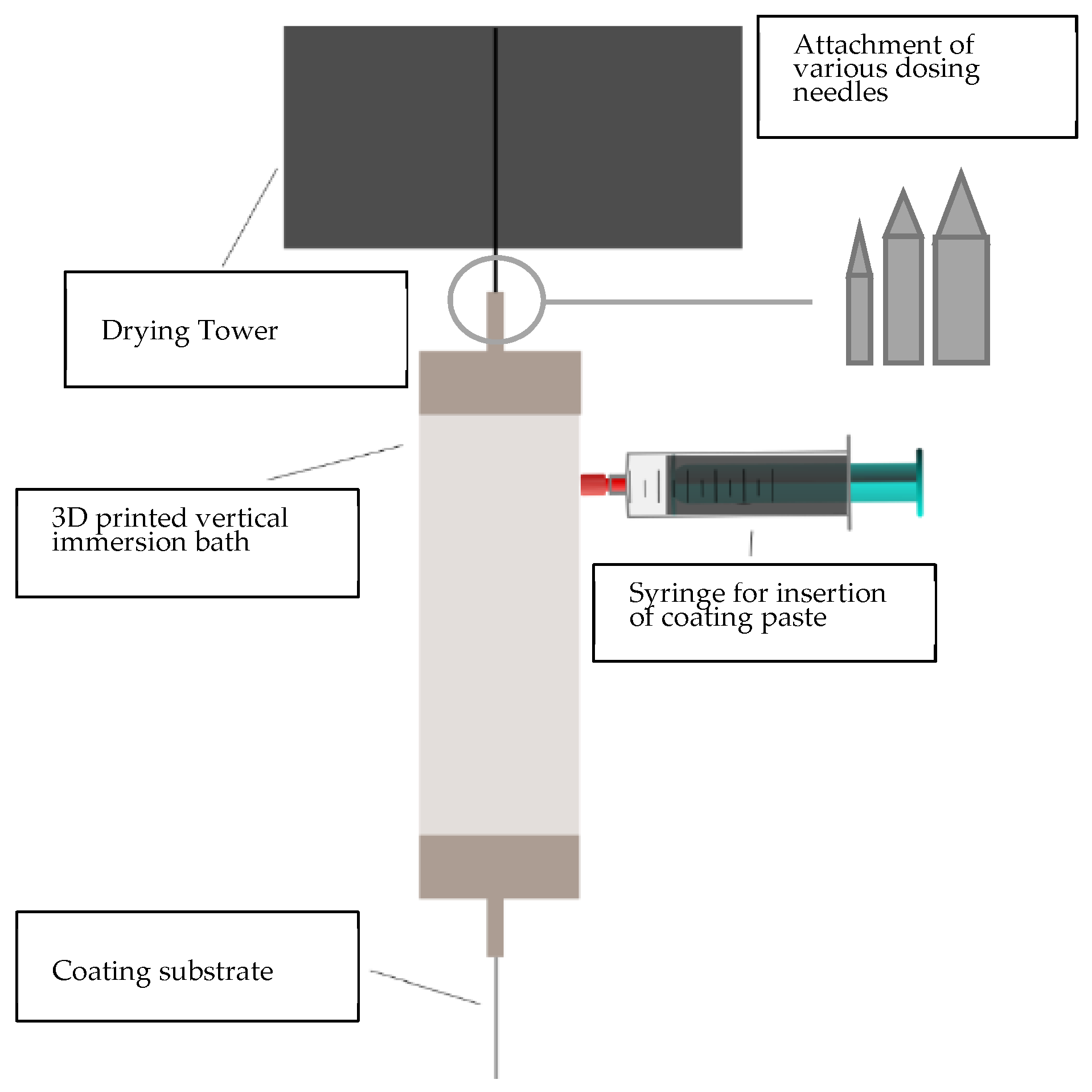
2.2.1. Coating of the Metallic Yarns
2.2.2. Optical Microscopy
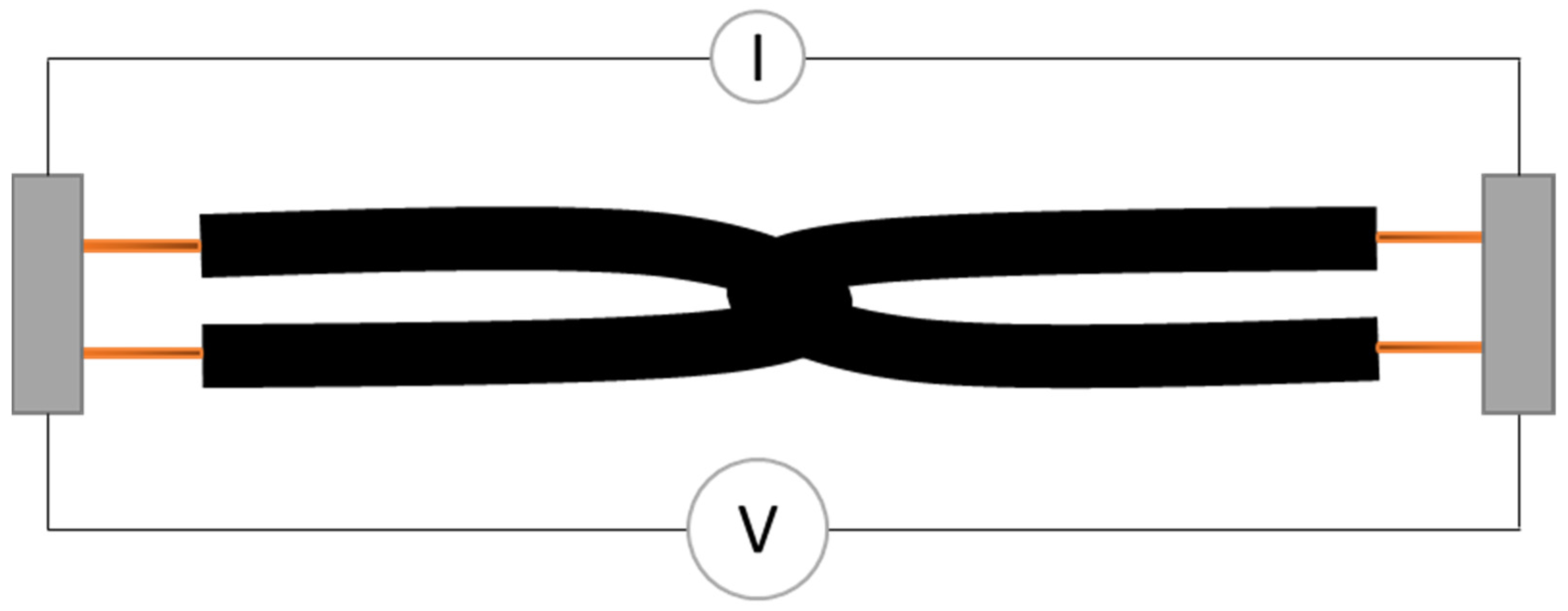
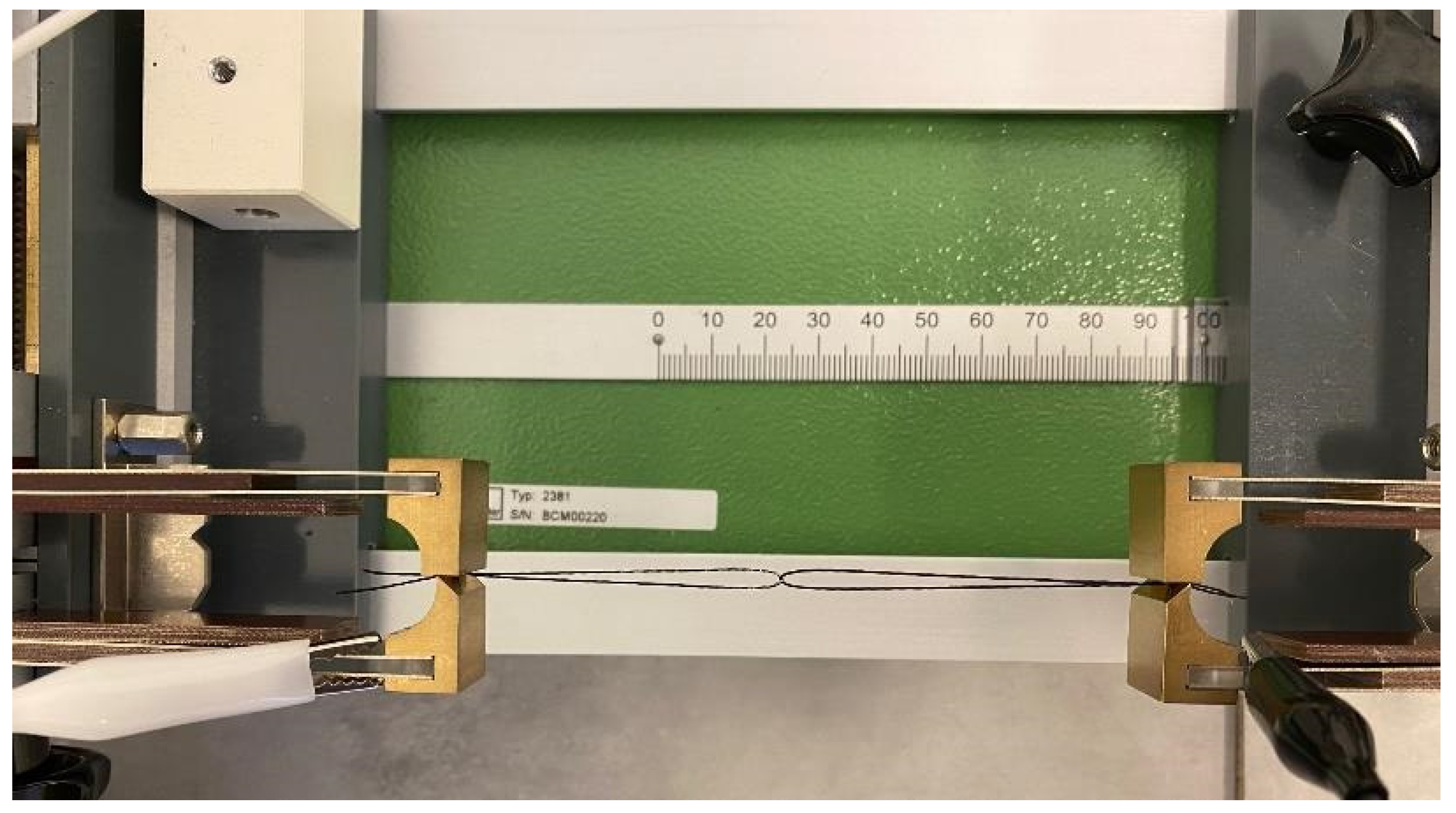
2.2.3. Electrical Resistance Measurements
3. Results
3.1. Layer Thickness
3.2. Optical Evaluation of the Samples
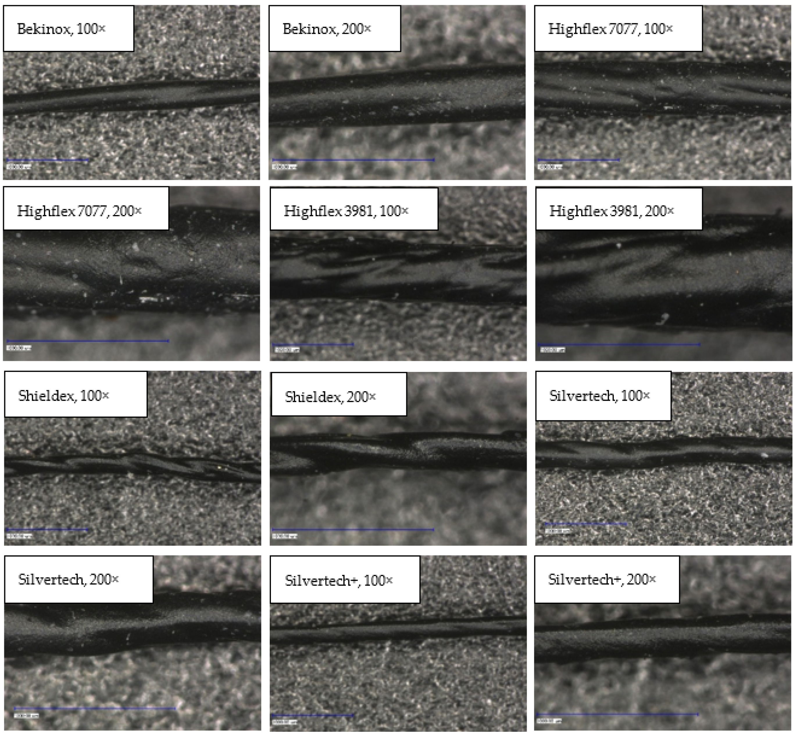
3.2.1. Longitudinal View
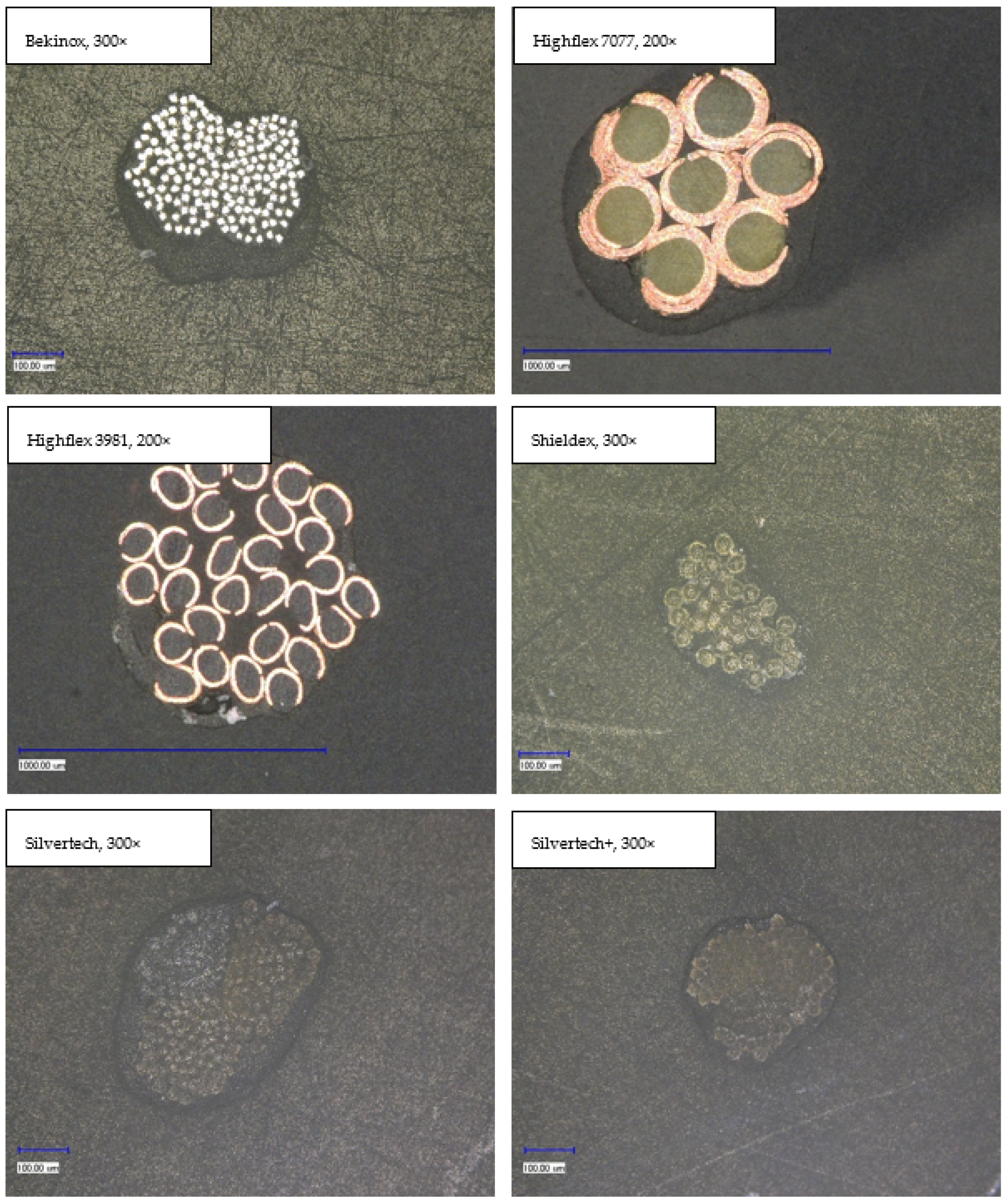
3.2.2. Cross-sectional View
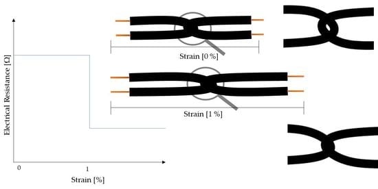
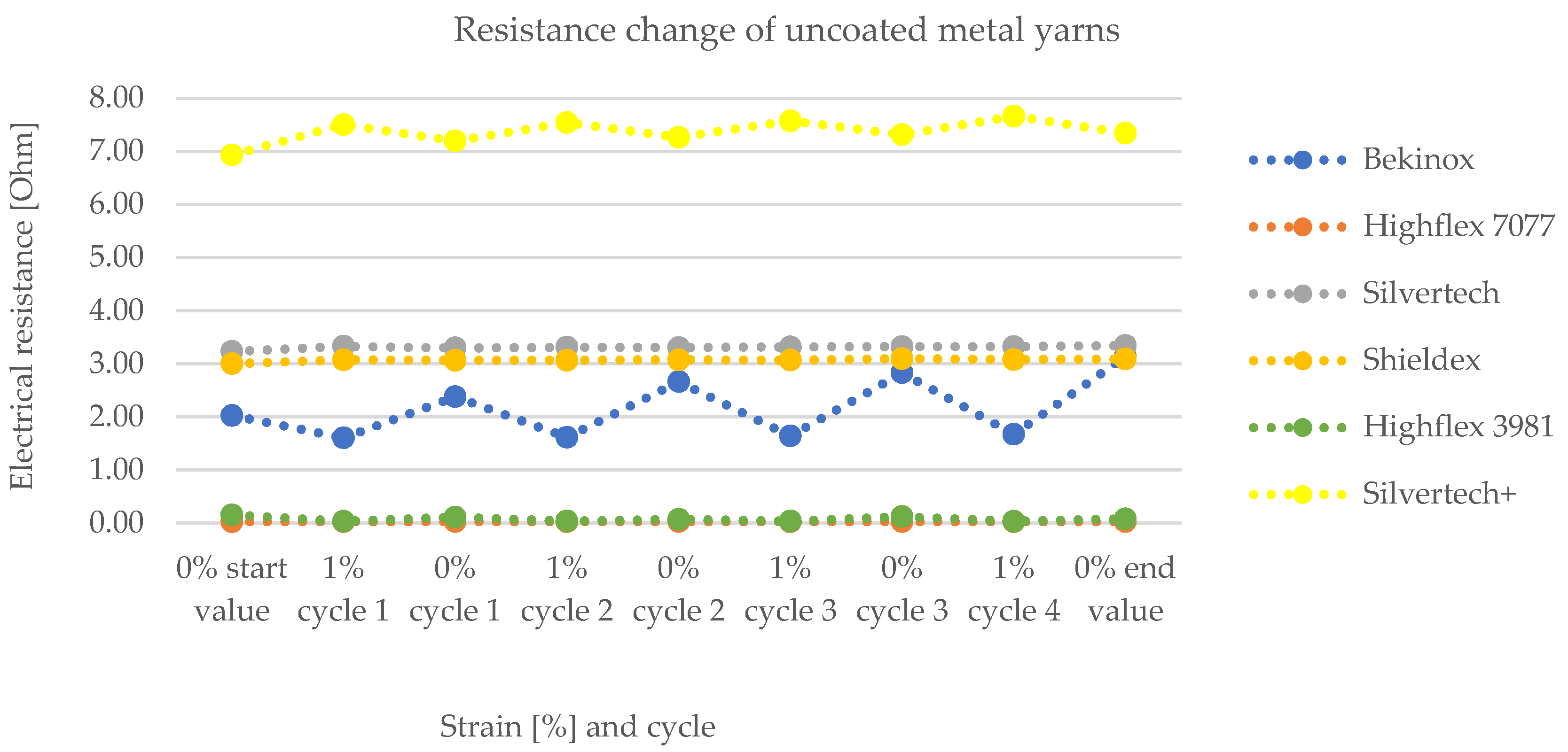
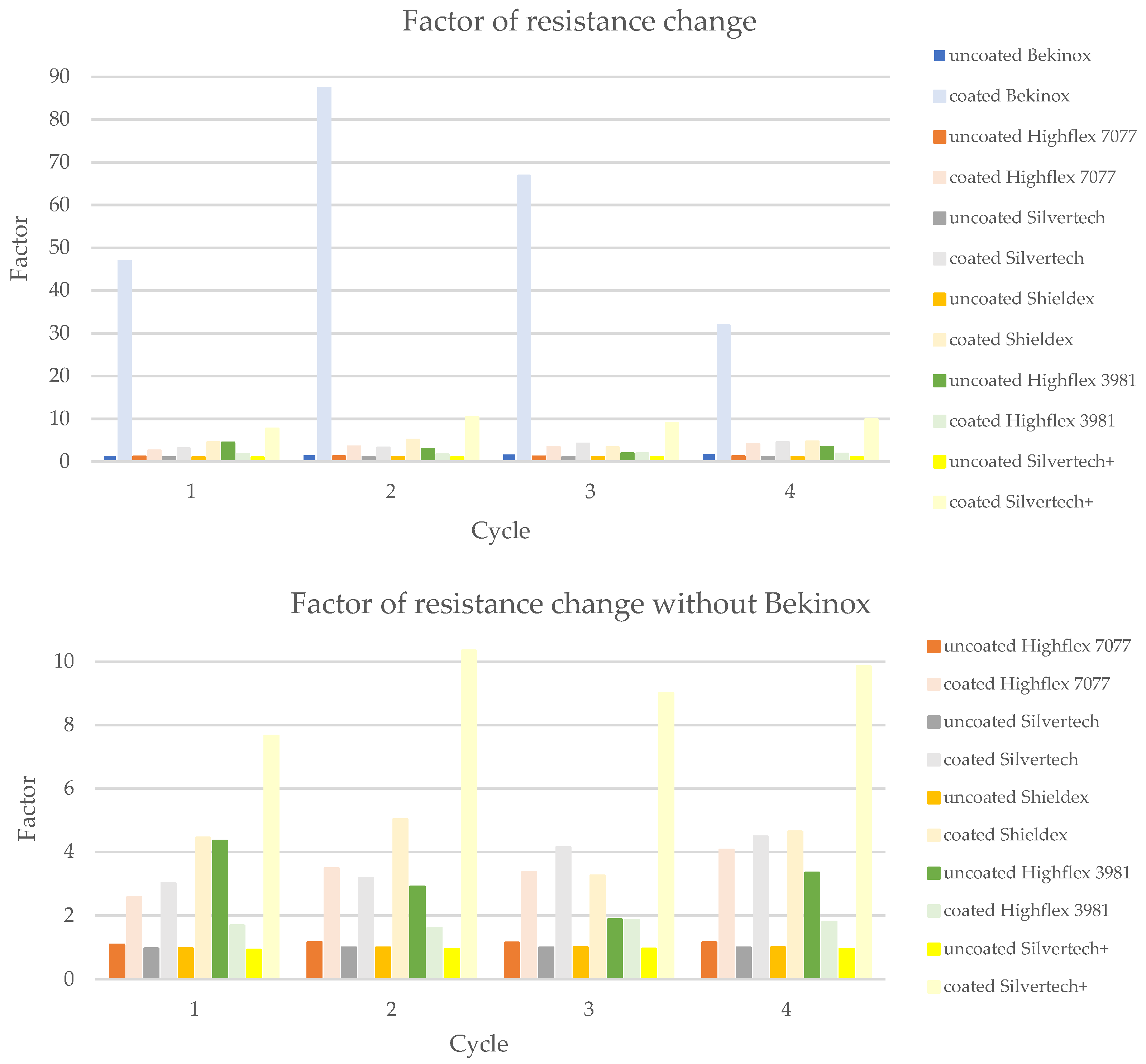
3.3. Resistance Measurements
4. Discussion
5. Conclusions
Author Contributions
Funding
Informed Consent Statement
Conflicts of Interest
References
- Webb, R.; Bonifas, A.P.; Behnaz, A.; Zhang, Y.; Yu, K.J.; Cheng, H.; Shi, M.; Bian, Z.; Liu, Z.; Kim, Y.-S.; et al. Ultrathin conformal devices for precise and continuous thermal characterization of human skin. Nat. Mater. 2013, 12, 938–944. [Google Scholar] [CrossRef] [PubMed]
- Wang, X.; Gu, Y.; Xiong, Z.; Cui, Z.; Zhang, T. Silk-Molded Flexible, Ultrasensitive, and Highly Stable Electronic Skin for Monitoring Human Physiological Signals. Adv. Mater. 2013, 26, 1336–1342. [Google Scholar] [CrossRef] [PubMed]
- Bingger, P.; Zens, M.; Woias, P. Highly flexible capacitive strain gauge for continuous long-term blood pressure monitoring. Biomed. Microdevices 2012, 14, 573–581. [Google Scholar] [CrossRef]
- Pang, C.; Lee, G.-Y.; Kim, T.-I.; Kim, S.M.; Kim, H.N.; Ahn, S.-H.; Suh, K.-Y. A flexible and highly sensitive strain-gauge sensor using reversible interlocking of nanofibres. Nat. Mater. 2012, 11, 795–801. [Google Scholar] [CrossRef] [PubMed]
- Amjadi, M.; Pichitpajongkit, A.; Lee, S.; Ryu, S.; Park, I. Highly Stretchable and Sensitive Strain Sensor Based on Silver Nanowire–Elastomer Nanocomposite. ACS Nano 2014, 8, 5154–5163. [Google Scholar] [CrossRef]
- Wang, J.; Lu, C.; Zhang, K. Textile-Based Strain Sensor for Human Motion Detection. Energy Environ. Mater. 2019, 3, 80–100. [Google Scholar] [CrossRef] [Green Version]
- Yang, Z.; Pang, Y.; Han, X.-L.; Yang, Y.; Ling, J.; Jian, M.; Zhang, Y.; Yang, Y.; Ren, T.-L. Graphene Textile Strain Sensor with Negative Resistance Variation for Human Motion Detection. ACS Nano 2018, 12, 9134–9141. [Google Scholar] [CrossRef]
- Kim, K.; Jung, M.; Jeon, S.; Bae, J. Robust and scalable three-dimensional spacer textile pressure sensor for human motion detection. Smart Mater. Struct. 2019, 28, 065019. [Google Scholar] [CrossRef]
- Zhu, C.; Li, R.; Chen, X.; Chalmers, E.; Liu, X.; Wang, Y.; Bin Xu, B.; Liu, X. Ultraelastic Yarns from Curcumin-Assisted ELD toward Wearable Human–Machine Interface Textiles. Adv. Sci. 2020, 7, 2002009. [Google Scholar] [CrossRef]
- Liao, X.; Song, W.; Zhang, X.; Huang, H.; Wang, Y.; Zheng, Y. Directly printed wearable electronic sensing textiles towards human–machine interfaces. J. Mater. Chem. C 2018, 6, 12841–12848. [Google Scholar] [CrossRef]
- Zhao, H.; Zhou, Y.; Cao, S.; Wang, Y.; Zhang, J.; Feng, S.; Wang, J.; Li, D.; Kong, D. Ultrastretchable and Washable Conductive Microtextiles by Coassembly of Silver Nanowires and Elastomeric Microfibers for Epidermal Human–Machine Interfaces. ACS Mater. Lett. 2021, 3, 912–920. [Google Scholar] [CrossRef]
- Fu, C.; Xia, Z.; Hurren, C.; Nilghaz, A.; Wang, X. Textiles in soft robots: Current progress and future trends. Biosens. Bioelectron. 2021, 196, 113690. [Google Scholar] [CrossRef] [PubMed]
- Amjadi, M.; Kyung, K.-U.; Park, I.; Sitti, M. Stretchable, Skin-Mountable, and Wearable Strain Sensors and Their Potential Applications: A Review. Adv. Funct. Mater. 2016, 26, 1678–1698. [Google Scholar] [CrossRef]
- Islam, G.M.N.; Ali, M.A.; Collie, S. Textile sensors for wearable applications: A comprehensive review. Cellulose 2020, 27, 6103–6131. [Google Scholar] [CrossRef]
- Seyedin, S.; Zhang, P.; Naebe, M.; Qin, S.; Chen, J.; Wang, X.; Razal, J.M. Textile strain sensors: A review of the fabrication technologies, performance evaluation and applications. Mater. Horizons 2018, 6, 219–249. [Google Scholar] [CrossRef]
- Yan, T.; Zhou, H.; Niu, H.; Shao, H.; Wang, H.; Pan, Z.; Lin, T. Highly sensitive detection of subtle movement using a flexible strain sensor from helically wrapped carbon yarns. J. Mater. Chem. C 2019, 7, 10049–10058. [Google Scholar] [CrossRef]
- Zhang, Q.; Wang, Y.L.; Xia, Y.; Zhang, P.F.; Kirk, T.V.; Chen, X.D. Textile-Only Capacitive Sensors for Facile Fabric Integration without Compromise of Wearability. Adv. Mater. Technol. 2019, 4, 1900485. [Google Scholar] [CrossRef]
- Atalay, O. Textile-Based, Interdigital, Capacitive, Soft-Strain Sensor for Wearable Applications. Materials 2018, 11, 768. [Google Scholar] [CrossRef] [Green Version]
- Jun, Z.; Chun-Na, L.; Wen-Liang, Z.; Hong, Z.; Yong-Feng, L.; Xue-Feng, H. Wearable respiratory strain monitoring system based on textile-based capacitive strain sensor. J. Physics: Conf. Ser. 2020, 1570, 012033. [Google Scholar] [CrossRef]
- Hu, C.-C.; Chang, S.-S.; Liang, N.-Y. Preparation and characterization of carbon black/polybutylene terephthalate/polyethylene terephthalate antistatic fiber with sheath–core structure. J. Text. Inst. 2015, 107, 976–984. [Google Scholar] [CrossRef]
- Shintake, J.; Piskarev, Y.; Jeong, S.H.; Floreano, D. Ultrastretchable Strain Sensors Using Carbon Black-Filled Elastomer Composites and Comparison of Capacitive Versus Resistive Sensors. Adv. Mater. Technol. 2018, 3, 1700284. [Google Scholar] [CrossRef] [Green Version]
- Choi, H.-J.; Kim, M.S.; Ahn, D.; Yeo, S.Y.; Lee, S. Electrical percolation threshold of carbon black in a polymer matrix and its application to antistatic fibre. Sci. Rep. 2019, 9, 6338. [Google Scholar] [CrossRef] [PubMed] [Green Version]
- Mattmann, C.; Clemens, F.; Tröster, G. Sensor for Measuring Strain in Textile. Sensors 2008, 8, 3719–3732. [Google Scholar] [CrossRef]
- Christ, J.F.; Aliheidari, N.; Pötschke, P.; Ameli, A. Bidirectional and Stretchable Piezoresistive Sensors Enabled by Multimaterial 3D Printing of Carbon Nanotube/Thermoplastic Polyurethane Nanocomposites. Polymers 2018, 11, 11. [Google Scholar] [CrossRef] [Green Version]
- Yeo, S.Y.; Jeong, S.H. Preparation and characterization of polypropylene/silver nanocomposite fibers. Polym. Int. 2003, 52, 1053–1057. [Google Scholar] [CrossRef]
- Jung, J.; Lee, S.; Pugno, N.M.; Ryu, S. Orientation Distribution Dependence of Piezoresistivity of Metal Nanowire-Polymer Composite. Multiscale Sci. Eng. 2020, 2, 54–62. [Google Scholar] [CrossRef] [Green Version]
- Schwarz, A.; Hakuzimana, J.; Kaczynska, A.; Banaszczyk, J.; Westbroek, P.; McAdams, E.; Moody, G.; Chronis, Y.; Priniotakis, G.; De Mey, G.; et al. Gold coated para-aramid yarns through electroless deposition. Surf. Coatings Technol. 2010, 204, 1412–1418. [Google Scholar] [CrossRef]
- Gehrke, I.; Gehrke, I.; Tenner, V.; Lutz, V.; Schmelzeisen, D.; Gries, T. Smart Textiles Production: Overview of Materials, Sensor and Production Technologies for Industrial Smart Textiles; MDPI: Basel, Switzerland, 2019. [Google Scholar]
- Eom, J.; Jaisutti, R.; Lee, H.; Lee, W.; Heo, J.-S.; Lee, J.-Y.; Park, S.K.; Kim, Y.-H. Highly Sensitive Textile Strain Sensors and Wireless User-Interface Devices Using All-Polymeric Conducting Fibers. ACS Appl. Mater. Interfaces 2017, 9, 10190–10197. [Google Scholar] [CrossRef] [PubMed]
- Klinkhammer, K.; Nolden, R.; Brendgen, R.; Niemeyer, M.; Zöll, K.; Schwarz-Pfeiffer, A. Coating of Silicone Monofilaments with Elastic Carbon Black-Silver-Silicone Layers and Their Characterization Especially with Regard to the Change of the Electrical Resistance in Dependence on Strain. Polymers 2022, 14, 806. [Google Scholar] [CrossRef]
- Wang, Z.; Huang, Y.; Sun, J.; Chunyi, Z.; Jiang, R.; Gai, W.; Li, G.; Zhi, C. Polyurethane/Cotton/Carbon Nanotubes Core-Spun Yarn as High Reliability Stretchable Strain Sensor for Human Motion Detection. ACS Appl. Mater. Interfaces 2016, 8, 24837–24843. [Google Scholar] [CrossRef]
- Cai, G.; Yang, M.; Pan, J.; Cheng, D.; Xia, Z.; Wang, X.; Tang, B. Large-Scale Production of Highly Stretchable CNT/Cotton/Spandex Composite Yarn for Wearable Applications. ACS Appl. Mater. Interfaces 2018, 10, 32726–32735. [Google Scholar] [CrossRef] [PubMed]
- Park, J.J.; Hyun, W.J.; Mun, S.C.; Park, Y.T.; Park, O.O. Highly Stretchable and Wearable Graphene Strain Sensors with Controllable Sensitivity for Human Motion Monitoring. ACS Appl. Mater. Interfaces 2015, 7, 6317–6324. [Google Scholar] [CrossRef]
- Ding, Y.; Yang, J.; Tolle, C.R.; Zhu, Z. A highly stretchable strain sensor based on electrospun carbon nanofibers for human motion monitoring. RSC Adv. 2016, 6, 79114–79120. [Google Scholar] [CrossRef]
- Gao, J.; Wang, X.; Zhai, W.; Liu, H.; Zheng, G.; Dai, K.; Mi, L.; Liu, C.; Shen, C. Ultrastretchable Multilayered Fiber with a Hollow-Monolith Structure for High-Performance Strain Sensor. ACS Appl. Mater. Interfaces 2018, 10, 34592–34603. [Google Scholar] [CrossRef] [PubMed]
- Tang, Z.; Jia, S.; Wang, F.; Bian, C.; Chen, Y.; Wang, Y.; Li, B. Highly Stretchable Core–Sheath Fibers via Wet-Spinning for Wearable Strain Sensors. ACS Appl. Mater. Interfaces 2018, 10, 6624–6635. [Google Scholar] [CrossRef] [PubMed]
- Li, Y.; Zhou, B.; Zheng, G.; Liu, X.; Li, T.; Yan, C.; Cheng, C.; Dai, K.; Liu, C.; Shen, C.; et al. Continuously prepared highly conductive and stretchable SWNT/MWNT synergistically composited electrospun thermoplastic polyurethane yarns for wearable sensing. J. Mater. Chem. C 2017, 6, 2258–2269. [Google Scholar] [CrossRef]
- Zhao, H.; Zhang, Y.; Bradford, P.D.; Zhou, Q.; Jia, Q.; Yuan, F.-G.; Zhu, Y. Carbon nanotube yarn strain sensors. Nanotechnology 2010, 21, 305502. [Google Scholar] [CrossRef]
- Liu, X.; Tang, C.; Du, X.; Xiong, S.; Xi, S.; Liu, Y.; Shen, X.; Zheng, Q.; Wang, Z.; Wu, Y.; et al. A highly sensitive graphene woven fabric strain sensor for wearable wireless musical instruments. Mater. Horizons 2017, 4, 477–486. [Google Scholar] [CrossRef]
- Wu, X.; Han, Y.; Zhang, X.; Lu, C. Highly Sensitive, Stretchable, and Wash-Durable Strain Sensor Based on Ultrathin Conductive Layer@Polyurethane Yarn for Tiny Motion Monitoring. ACS Appl. Mater. Interfaces 2016, 8, 9936–9945. [Google Scholar] [CrossRef]
- Wajahat, M.; Lee, S.; Kim, J.H.; Chang, W.S.; Pyo, J.; Cho, S.H.; Seol, S.K. Flexible Strain Sensors Fabricated by Meniscus-Guided Printing of Carbon Nanotube–Polymer Composites. ACS Appl. Mater. Interfaces 2018, 10, 19999–20005. [Google Scholar] [CrossRef]
- Multidisciplinary Know-How for Smart-Textiles Developers, 1st Edition. Available online: https://www.elsevier.com/books/multidisciplinary-know-how-for-smart-textiles-developers/kirstein/978-0-85709-342-4 (accessed on 19 May 2022).
- Brendgen, R.; Graßmann, C.; Grethe, T.; Mahltig, B.; Schwarz-Pfeiffer, A. Coatings with recycled polyvinyl butyral on polyester and polyamide mono- and multifilament yarns. J. Coatings Technol. Res. 2021, 18, 819–829. [Google Scholar] [CrossRef]
- Kazani, I.; Hertleer, C.; Mey, G.; Schwarz-Pfeiffer, A.; Guxho, G.; van Langenhove, L. Electrical Conductive Textiles Obtained by Screen Printing. Fibres Text. East. Eur. 2012, 1, 57–63. [Google Scholar]
- Kazani, I.; De Mey, G.; Hertleer, C.; Banaszczyk, J.; Schwarz, A.; Guxho, G.; van Langenhove, L. Van Der Pauw method for measuring resistivities of anisotropic layers printed on textile substrates. Text. Res. J. 2011, 81, 2117–2124. [Google Scholar] [CrossRef]
- Tokarska, M.; Frydrysiak, M.; Zięba, J. Electrical properties of flat textile material as inhomegeneous and anisotropic structure. J. Mater. Sci. Mater. Electron. 2013, 24, 5061–5068. [Google Scholar] [CrossRef] [Green Version]
- Tokarska, M.; Gniotek, K. Anisotropy of the electrical properties of flat textiles. J. Text. Inst. 2014, 106, 9–18. [Google Scholar] [CrossRef]


| Name | Manufacturer | Composition | Resistance | Fineness (Dtex) | Light-Microscopy Image |
|---|---|---|---|---|---|
| Bekinox | NV Bekaert SA (Zwevegem Belgium) | Stainless steel | 29 Ohm/m | 2500 | 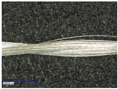 |
| Highflex 7077 | Karl Grimm GmbH & Co. KG (Roth, Germany) | Silver-plated copper, Carrier material: Kevlar | 0.41 Ohm/m | N/A | 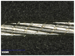 |
| Highflex 3981 | Karl Grimm GmbH & Co. KG (Roth, Germany) | Copper, carrier material: polyethylene terephthalate | 0.55 Ohm/m | N/A | 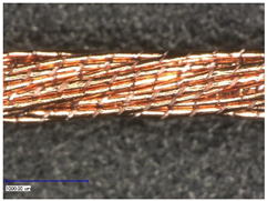 |
| Shieldex | Statex Produktions- und Vertriebs GmbH (Bremen, Germany) | Silver-plated polyamide multifilament yarn | < 300 Ohm/m | 295 | 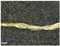 |
| Silvertech | Amann & Söhne GmbH & Co. KG (Bönnigheim, Germany) | Silver coated polyamide/polyester hybrid twine | <150 Ohm/m | 210 *3 | 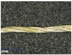 |
| Silvertech+ | Amann & Söhne GmbH & Co. KG (Bönnigheim, Germany) | Silver coated polyamide multifilament | < 200 Ohm/m | 110 *3 | 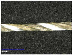 |
| Substrate | Mean Carbon Silicone Coating Thickness |
|---|---|
| Bekinox | 46.18 µm |
| Highflex 7077 | 54.44 µm |
| Highflex 3981 | 41.16 µm |
| Shieldex | 27.25 µm |
| Silvertech | 26.60 µm |
| Silvertech+ | 21.85 µm |
| Substrate | Uncoated | Coated |
|---|---|---|
| Bekinox | −37.3241 | −98.2304 |
| Highflex 7077 | −13.0815 | −69.6716 |
| Highflex 3981 | −65.5768 | −41.9042 |
| Shieldex | 0.2092 | −77.4867 |
| Silvertech | 0.5909 | −72.2907 |
| Silvertech+ | 4.9875 | −89.0990 |
| Bekinox | Highflex 7077 | Highflex 3981 | Shieldex | Silvertech | Silvertech+ | |||||||
|---|---|---|---|---|---|---|---|---|---|---|---|---|
| Uncoated | Coated | Uncoated | Coated | Uncoated | Coated | Uncoated | Coated | Uncoated | Coated | Uncoated | Coated | |
| Coating thickness [µm] | / | 46.18 | / | 54.44 | / | 41.16 | / | 27.25 | / | 26.60 | / | 21.85 |
| Factor of resistance change | 1.5121 | 58.2359 | 1.1409 | 3.3727 | 3.1184 | 1.7370 | 0.9959 | 4.3439 | 0.9908 | 3.7081 | 0.9480 | 9.2134 |
| Gauge factor | −37.3241 | −98.2304 | −13.0815 | −69.6716 | -65.5768 | −41.9042 | 0.2092 | −77.4867 | 0.5909 | −72.2907 | 4.9875 | −89.0990 |
Publisher’s Note: MDPI stays neutral with regard to jurisdictional claims in published maps and institutional affiliations. |
© 2022 by the authors. Licensee MDPI, Basel, Switzerland. This article is an open access article distributed under the terms and conditions of the Creative Commons Attribution (CC BY) license (https://creativecommons.org/licenses/by/4.0/).
Share and Cite
Brendgen, R.; Nolden, R.; Simon, J.; Junge, T.; Zöll, K.; Schwarz-Pfeiffer, A. Textile Strain Sensor Enhancement by Coating Metal Yarns with Carbon-Filled Silicone. Polymers 2022, 14, 2525. https://doi.org/10.3390/polym14132525
Brendgen R, Nolden R, Simon J, Junge T, Zöll K, Schwarz-Pfeiffer A. Textile Strain Sensor Enhancement by Coating Metal Yarns with Carbon-Filled Silicone. Polymers. 2022; 14(13):2525. https://doi.org/10.3390/polym14132525
Chicago/Turabian StyleBrendgen, Rike, Ramona Nolden, Jasmin Simon, Theresa Junge, Kerstin Zöll, and Anne Schwarz-Pfeiffer. 2022. "Textile Strain Sensor Enhancement by Coating Metal Yarns with Carbon-Filled Silicone" Polymers 14, no. 13: 2525. https://doi.org/10.3390/polym14132525
APA StyleBrendgen, R., Nolden, R., Simon, J., Junge, T., Zöll, K., & Schwarz-Pfeiffer, A. (2022). Textile Strain Sensor Enhancement by Coating Metal Yarns with Carbon-Filled Silicone. Polymers, 14(13), 2525. https://doi.org/10.3390/polym14132525