Abstract
Polymers are used widely in the power system as insulating materials and are essential to the power grid’s security and stability. However, various insulation defects may occur in the polymer., which can lead to severe insulation accidents. Terahertz (THz) detection is a novel non-destructive testing (NDT) method that is able to detect the interface structures inside polymers. The large quantity of information in the THz waveform has potential for the identification of interface types, and the long short-term memory (LSTM) network is one of the most popular artificial intelligence methods for time series data like THz waveform. In this paper, the LSTM classification network was used to identify the internal interfaces of the polymer with the reflected THz pulses of the internal interfaces. The experiment verified that it is feasible to identify and image the void interfaces and impurity interfaces in the polymer using the proposed method.
1. Introduction
As the scale of the power grid continues to grow, more and more insulation equipment is being used in the power grid [1]. However, during manufacturing, transportation, installation, and operation, many defects caused by human or environmental factors may occur in the insulating material [2,3,4]. These defects can cause continuous degradation of the insulation performance and eventually lead to insulation accidents, resulting in economic losses and human casualties [5,6]. Therefore, in practical applications, there is an urgent need for effective non-destructive testing (NDT) methods for internal defects.
The commonly used NDT methods have their limitations. For example, ultrasonic testing requires a coupling agent for contact detection and has high demands on the ability of operators [7]. Infrared detection can only be applied for detecting the defects that cause external temperature changes and is highly influenced by environmental conditions [8]. Microwave inspection is also a contacting method with very few feature parameters, and can only qualitatively determine the presence of defects [9]. X-ray is harmful to humans, and its strong penetration ability makes it easy to directly pass through the defect, resulting in missed detection [10].
Terahertz (THz) technology is an emerging NDT method, in which the electromagnetic waves in the THz band (0.1–10 THz) are used to achieve a non-contact, safe, and efficient NDT. It has been widely used in fields such as security screening [11,12,13], biomedicine [14,15,16], and aerospace [17,18]. Meanwhile, using the property that THz waves can detect the internal interface structures of polymers, it has also been applied in the detection of power insulation defects [19,20,21]. However, most of the existing studies focus on detecting the location, size, and shape of the internal interface using macroscopic features of THz waveform (such as peak value, time delay, and other parameters). Very few studies focus on using the microscopic features of pulses in THz waves to identify the type of the interface, which is also very meaningful for the detection. The long short-term memory (LSTM) network is one of the most common current artificial intelligence methods for processing time-series data [22,23]. It has been proven to be suitable for the THz time domain waveform data [24]. Therefore, the LSTM network has great potential for interface identification in polymers.
In this paper, an internal interface identification method is proposed for polymer detection, which is based on THz waves and LSTM classification networks. Three different artificial interface samples were made to collect THz waveform data to train the LSTM. Then, the trained LSTM was used to identify and image the internal interfaces in other samples to test its performance.
2. Theory and Methodology
2.1. Terahertz Detection Theory
Assuming that a THz wave is incident vertically from medium 1 to medium 2, the refraction coefficient and the reflection coefficient at the interface “1–2” can be expressed as [25]
where and represent complex refractive indices of the medium 1 and medium 2, respectively.
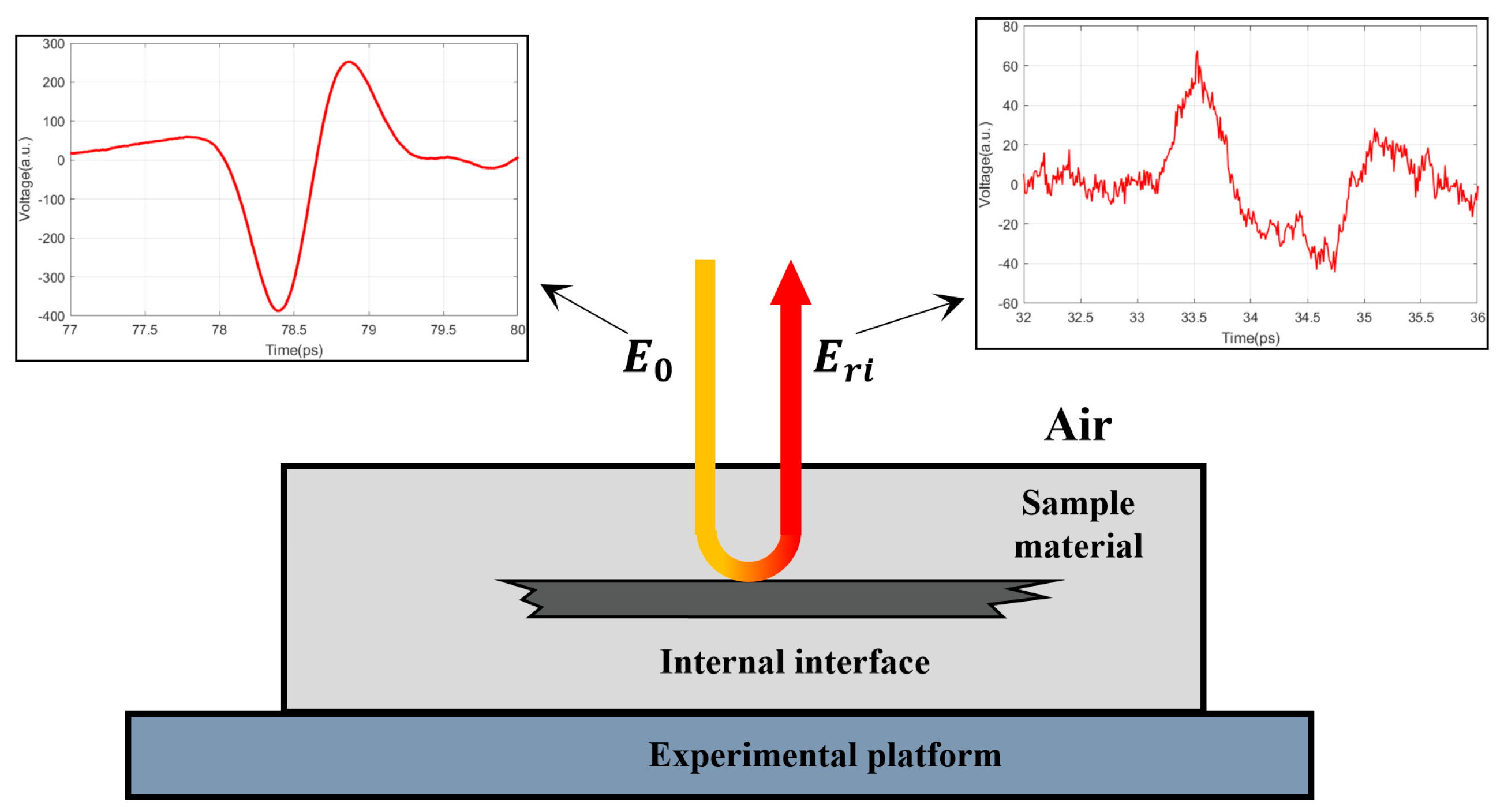
Many insulating materials are polymers that are translucent to THz waves [26]. Thus, THz waves can propagate through insulating materials and be reflected by internal interfaces such as the defect structure. Figure 1 shows this process. A THz pulse is incident into the sample, when it encounters an internal interface structure, a reflected pulse will be generated, which can be expressed as follows [27]:
where is the wave frequency. a, b, and c represent the air, sample material, and the internal interface, respectively. and are the propagating distances of THz wave in the air and the sample material, respectively. The propagation coefficient represents the amplitude attenuation and phase change of the THz wave when propagating in the medium, which can be described as follows [27]
where is the vacuum speed of light.
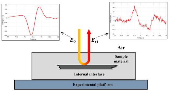
Figure 1.
Schematic diagram of detecting an internal interface structure with THz waves.
According to Equations (1)–(4), the reflected wave contains information about the properties of the interface structure. In turn, it is theoretically feasible to identify the interface type by the reflected wave.
2.2. LSTM Theory
LSTM is a model structure of recurrent neural networks (RNN). In contrast with the conventional RNN, three gates are placed in each LSTM unit, including an input gate, an output gate, and a forget gate. Based on this special structure, LSTM effectively overcomes the vanishing gradient problem, which greatly limits classic RNNs [28]. A typical LSTM structure is shown in Figure 2.
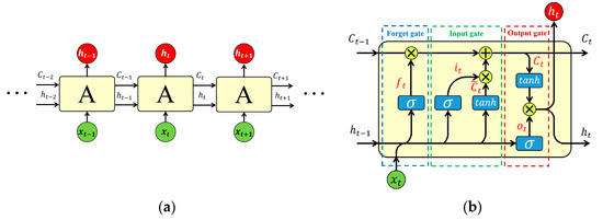
Figure 2.
Schematic diagram of the LSTM structure. (a) Chain structure of LSTM and (b) LSTM unit architecture.
As shown in Figure 2b, the forget gate output can be expressed as
where represents the weight matrix of the forget gate, which is to be changed during training, is the output vector of the last unit, is the input vector of the current unit, is the bias vector, which will also be changed in the training process, and represents the sigmoid function, which can be expressed as
From Equation (6), it can be seen that each number in is between 0 and 1, which represents the degree of forgetting for this part of information. Therefore, the forget gate determines which part of the information to be kept and which to be rid of.
The input gate determines which information will be used to update the cell state vector . The input gate equations are:
where and are the weight matrices of input gate and cell state, respectively. and are the biases of the input gate and cell state, respectively. is the output vector of the input gate, is the cell input activation vector, is the cell state vector, and represents the element-wise product.
Finally, the output gate determines what information will be output by the following equations:
where is the output vector of the output gate, is the output vector of the LSTM unit, and and are the weight matrix and bias of output gate, respectively.
3. Experiment Setup
3.1. Experimental Samples
Various interfaces can be inside insulating polymers. Void interfaces are very common in power insulation equipment, which can lead to a severe degradation of insulation performance [29]. When internal defects have developed to a certain degree, partial breakdown may occur, which can result in carbonization channels [30,31]. In addition, metal interfaces can also occur in insulation equipment, such as the metal sheaths of high-voltage cables [32], as well as metal impurities that intrude into the material during manufacture and operation [33,34]. Therefore, in this paper, three artificial interface samples were made to simulate the internal interfaces of the polymers, including the void interface, the carbonized interface, and the metal interface. Polyethylene (PE) was used as the insulating polymer. The artificial interface samples used to collect training data for LSTM are shown in Figure 3.
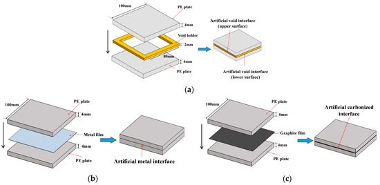
Figure 3.
Structure of artificial interface samples for collecting LSTM training data: (a) artificial void interfaces; (b) artificial metal interface; (c) artificial carbonized interface.
As shown in Figure 3, the size of the PE plate was 100 mm × 100 mm × 4 mm. For the artificial void interface sample, a resin holder with a size of 100 mm × 100 mm × 2 mm was placed between the upper and lower PE plates, which had a void area of 80 mm × 80 mm in its center. They were stacked on top of each other to simulate the upper surface (“polymer−air” interface (PA)) and the lower surface (“air−polymer” interface (AP)) of the void. To simulate metal and carbonized interfaces in the polymer, an aluminum film and a graphite film were placed between two PE plates, respectively. Different from the void interface, THz waves cannot penetrate metal and carbonized interfaces. Thus, these two artificial samples are only with the “polymer−metal” (PM) interface and the “polymer−carbonization” (PC) interface, respectively.
In addition, another PE sample was used in this paper to test the performance of the trained LSTM, and the size and shape of the sample are shown in Figure 4a. The sample was a PE block with five holes, which can simulate voids at different depths in the polymer. As shown in Figure 4b, by inserting aluminum rods and graphite rods in the holes, the metal interfaces and the carbonized interfaces in the polymer can also be simulated.
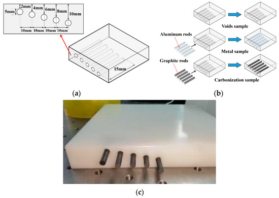
Figure 4.
Artificial interface samples for testing the LSTM performance in 3D imaging: (a) shape and size; (b) three different types of interface; (c) picture of the real carbonization sample.
3.2. THz System
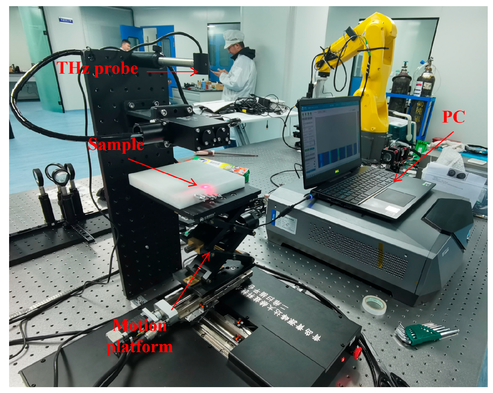
In this paper, QT-TO1000 from Quenda Technology Ltd., China, was used as the THz time domain spectroscopy system, which can emit and receive electromagnetic waves of 0.1–3.5 THz. Its maximum scanning area is up to 100 mm × 100 mm with a step length of 0.3 mm, and its scanning speed is up to 60 pixels per second. As shown in Figure 5, the whole system includes a THz probe, a motion system, and a PC. The THz probe is used to emit and receive the THz waves, and the motion platform is driven by three motors in X, Y, and Z directions, respectively. Both of them are connected to the PC, which controls the motion platform and collects the THz waves’ data to realize the scanning of samples.
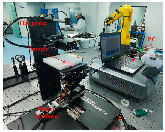
Figure 5.
The THz time domain spectroscopy system.
4. Experiments and Discussion
4.1. LSTM Training
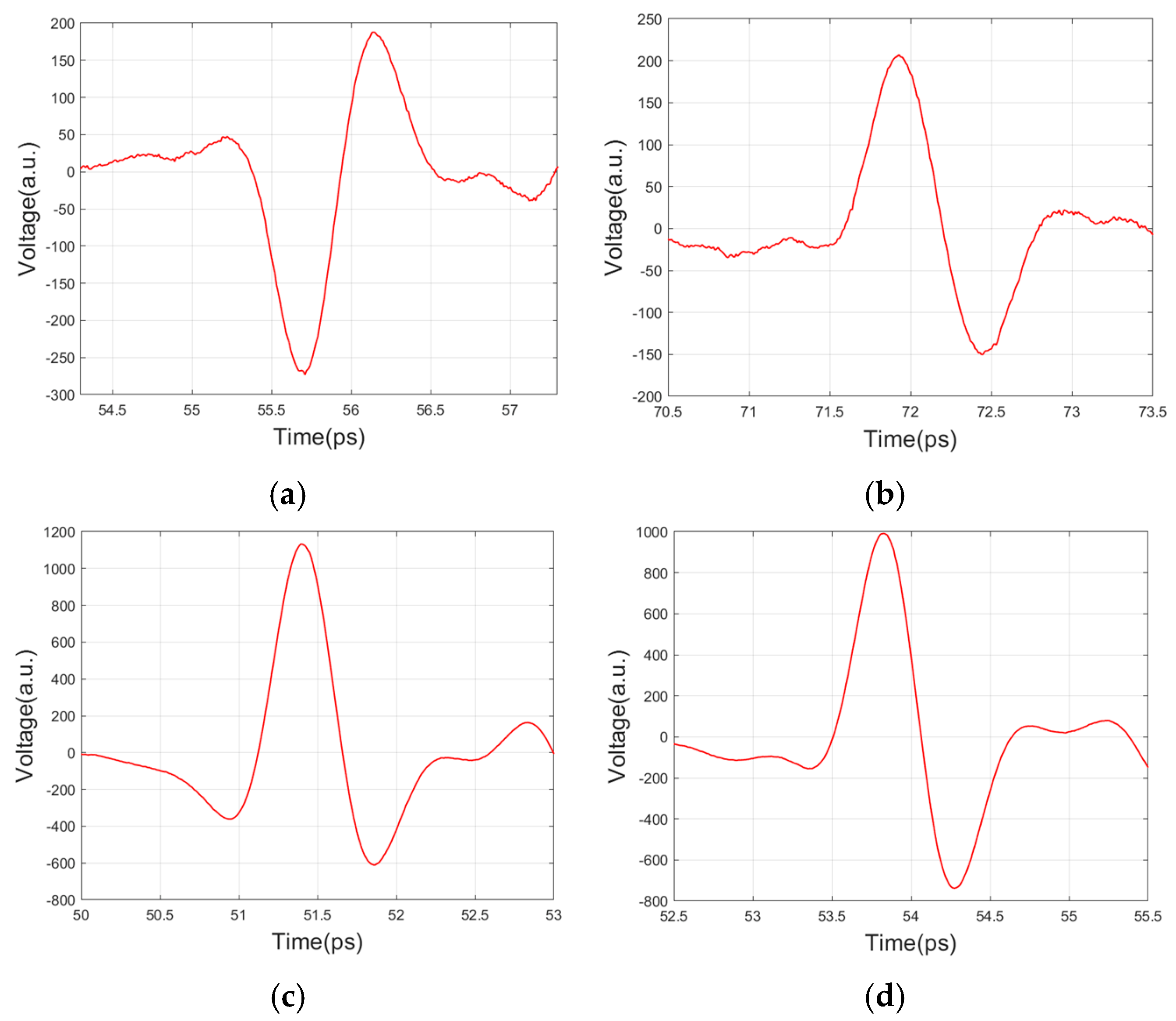
First, waveform data were collected from artificial interface samples for the training of LSTM. The sample was placed on the motion platform. Before collecting data, the height of the platform was adjusted to make sure that the artificial interface was near the focus of the THz beam, in which case the reflected pulse amplitude would reach the maximum. A 50 mm × 50 mm area in the center of three artificial interface samples was scanned, separately, in a step length of 1 mm. Then, the reflected waveform data of the artificial interface samples could be collected. Typical reflected pulse waveforms are shown in Figure 6.
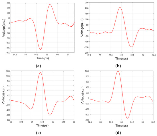
Figure 6.
Typical reflected pulse waveforms of artificial interfaces: (a) PA interface; (b) AP interface; (c) PM interface; (d) PC interface.
After that, the pulse data of the artificial interfaces were extracted from the scanned waveforms. As shown in Figure 7, and are the start time and end time of the pulse, respectively, and is the absolute maximum time (positive or negative peak) of the pulse. The positions of and can be determined by , which can be expressed as
where is a random perturbation term, which made the training data more diverse so as to improve the generalization capability of the network.
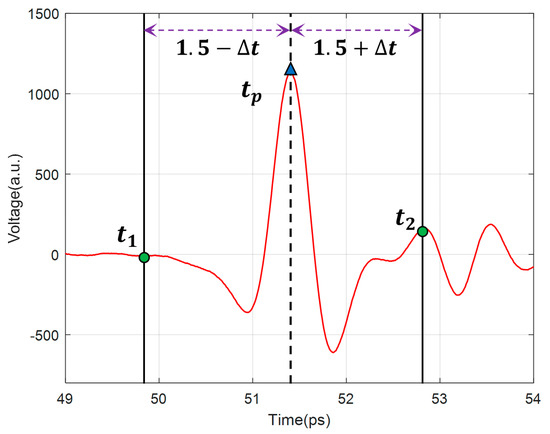
Figure 7.
Schematic diagram of pulse data extracting.
Then, the pulse data sets of the artificial PA interface , artificial AP interface , artificial PM interface , and artificial PC interface can be obtained.
Given that the interfaces inside the actual polymers are usually not exactly at the beam focus, and the amplitude of their reflected pulse will probably decrease. Therefore, the amplitude of the training data should also be randomly reduced to enhance the performance of the trained network. The random reduction process can be expressed as
where , , , and are the random reduction factors of the four artificial interfaces, respectively. As a pulse with a too small amplitude is hard to distinguish from the background noise, a threshold value should be set. All of the valid pulses must have an absolute maximum larger than . In this paper, . As shown in Figure 6, different interfaces have different pulse amplitudes. Therefore, the random reduction factors should have different lower limits to ensure all pulses in the training data are valid. Finally, the training set , , can be obtained.
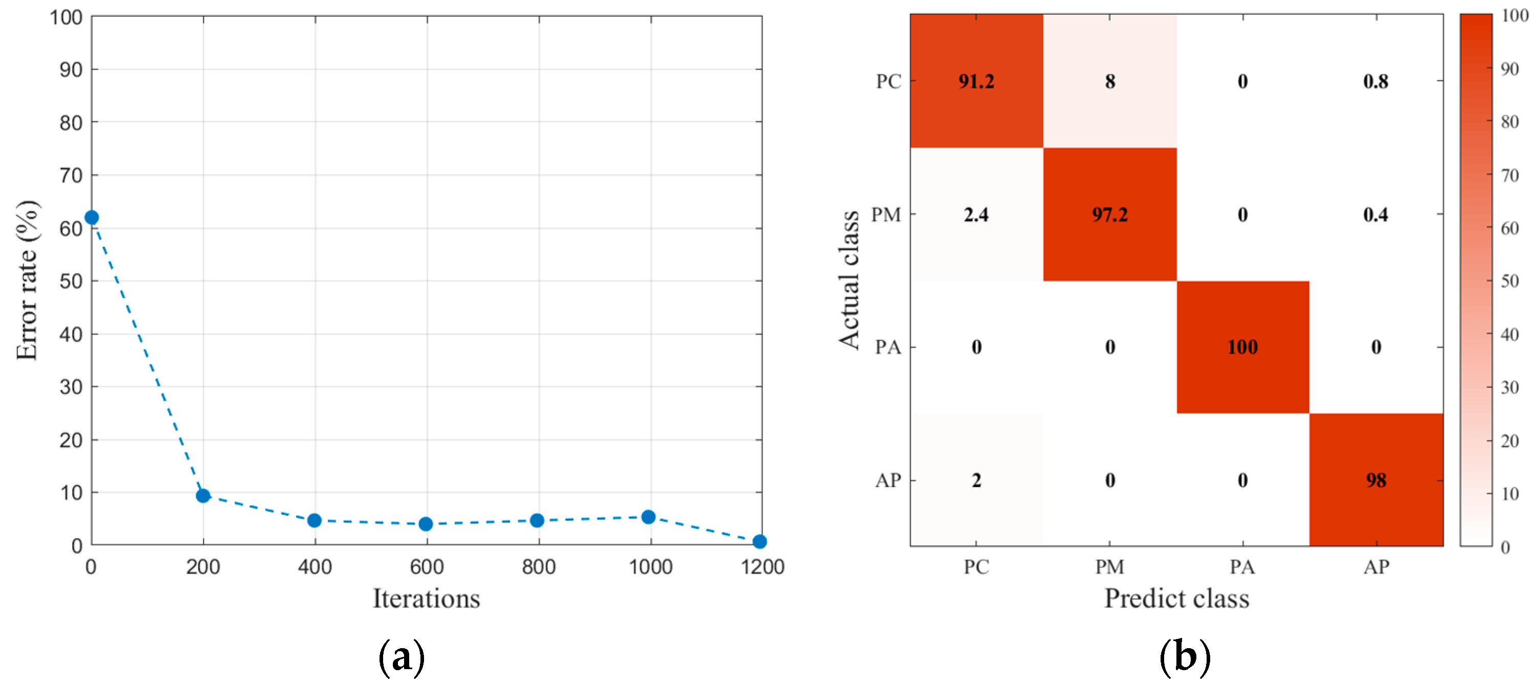
The training set was divided into two parts. One part was used to train the LSTM with 2250 pulse data for each type of interface, another one was as the validation set to test the accuracy of the trained LSTM. The LSTM network was established and was trained by the training set. The input dimension of LSTM was 300, which was the same as the length of pulse data. The LSTM layer was the bi-directional structure with 100 hidden units. The maximum number of iterations was 1200, the learning rate was 0.01, and the gradient threshold was 1.
The training results are shown in Figure 8. It can be seen that this LSTM has a good classification performance for the artificial interfaces.
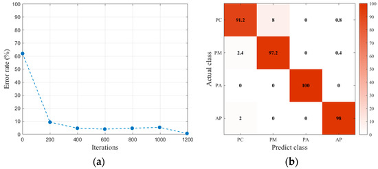
Figure 8.
Training results of LSTM: (a) training error rate of LSTM; (b) classification accuracy of the validation set.
4.2. 3D Identification Imaging Test
The holes in the PE block can be imaged in 3D as follows: After the PE block sample was scanned, all the valid pulses in the scanning waveforms data were extracted by the rule of Equation (13) with , and . Each pulse corresponded to a point of a certain interface. According to basic optics laws, its location can be calculated by
where is the spatial coordinates of the point, and are the numbers of scanning steps in the X direction and the Y direction, respectively, is the scanning step length, is the vacuum light speed, and is the refraction index of PE. Depending on the composition and wave frequency, is in a range of 1.51–1.54 [35]. In this paper, . As the THz probe was above the sample as shown in Figure 5, the z-axis coordinate of each point should be negative.
After that, the pulse data are classified by the trained LSTM, and each point will be labeled with a certain interface class. Thus, 3D identification imaging can be realized.
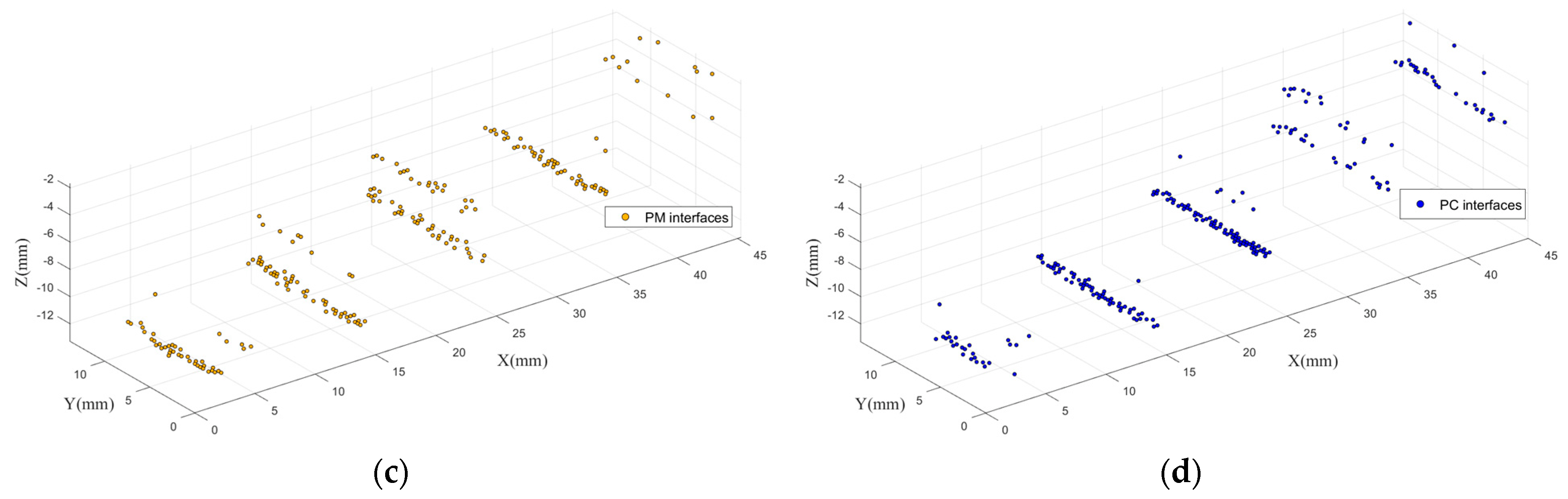
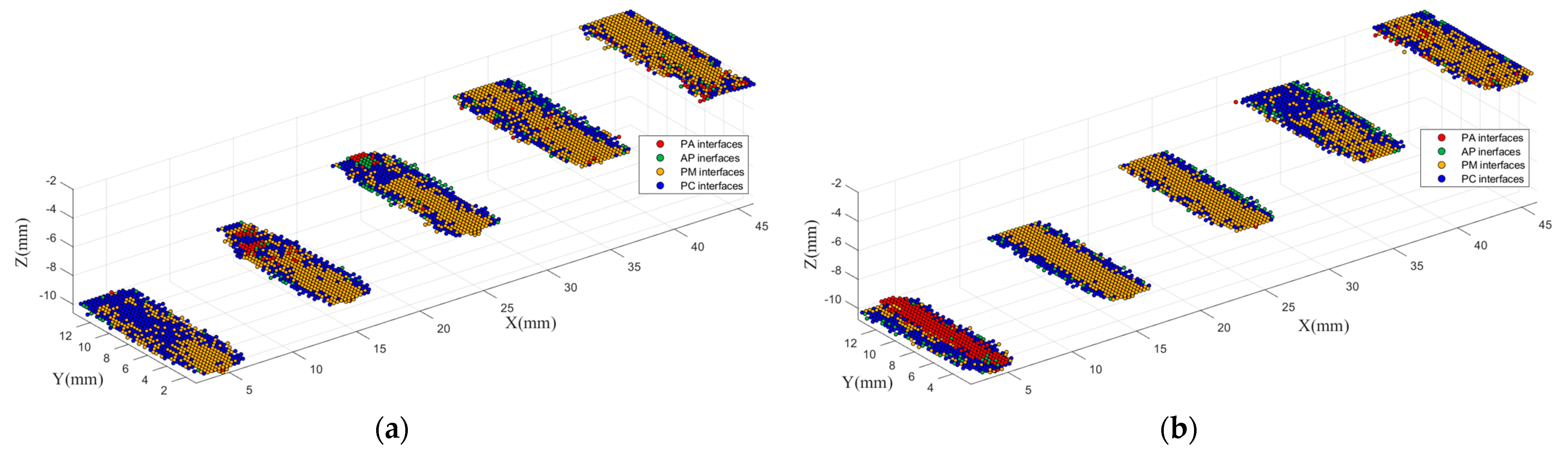
As the attenuation of propagating in material, deviation from the focus, and the non-flat interface structures, the interfaces inside the PE block sample are more complicated and more similar to an actual situation. Therefore, the PE block sample can be used to test the feasibility of 3D identification imaging with trained LSTM in a relatively actual situation. The 3D identification imaging results of the PE block sample of voids are shown in Figure 9.
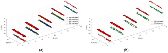
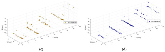
Figure 9.
3D identification imaging results of PE block sample of voids. (a) Results of all identified points; (b) results of points identified as voids; (c) results of points identified as metal; (d) results of points identified as carbonization.
As it can be seen, the upper surfaces of the voids are identified better than the lower surfaces. Let I–V represent the five holes at depths from 2 mm to 10 mm, respectively. The number of different points in the result of the PE block sample of voids is listed in Table 1.

Table 1.
Number of different points in the imaging results of the PE block sample of the voids.
From Table 1, the PA interfaces are identified well at all depths. Compared with the PA interfaces, both the correct identification rates and the numbers of points of the AP interfaces are lower. However, for AP interfaces I–IV, the AP points are still the most. For void V, the identification performance of the AP interface is poor. The reason could be that the interface was greatly out of focus, which caused strong attenuation of the THz waves. It also can be seen that the number of all points varied greatly with depth. Therefore, the depth could greatly influence the imaging performance of the voids.
The PE block samples of the metal and carbonization were also imaged in the same way, respectively. The results are shown in Figure 10 and Table 2 and Table 3.

Figure 10.
3D identification imaging results of PE block sample of metal and carbonization: (a) PE block sample of metal; (b) PE block sample of carbonization.
Table 2.
Number of different points in the imaging results of the PE block sample of metal.
Table 3.
Number of different points in the imaging results of the PE block samples of carbonization.
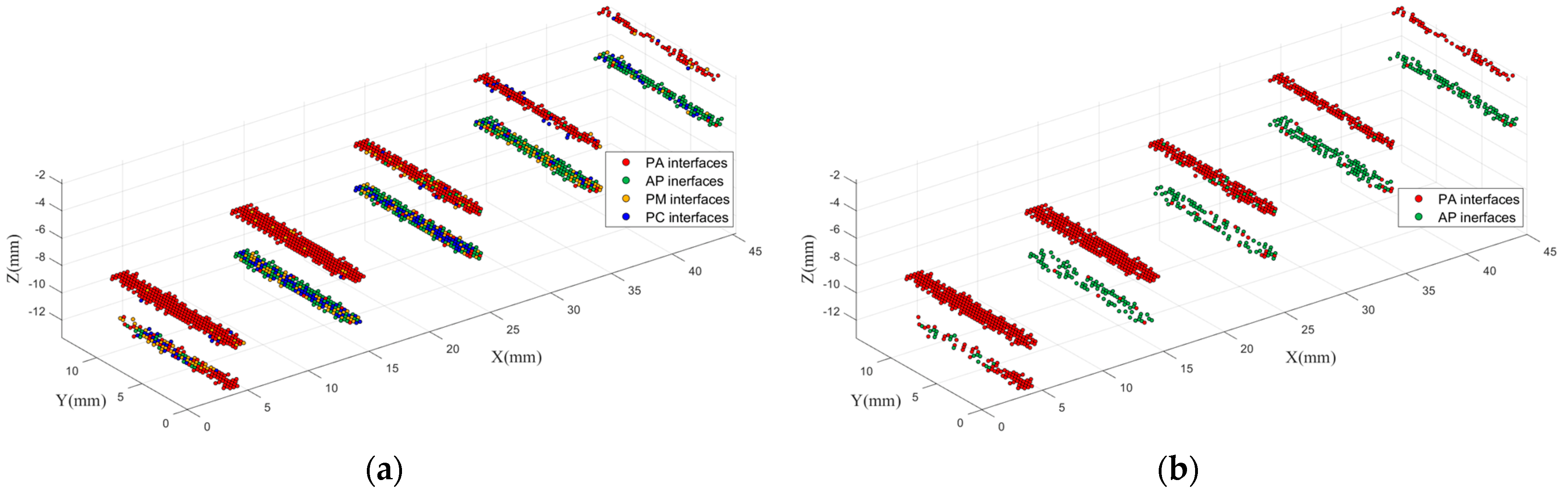
As it can be seen, compared with voids, the depth does not affect the imaging performance much for the PM interfaces and the PC interfaces. On the other hand, the PM interfaces and the PC interfaces tend to be confused, which is different from the results of the training. In particular, the PC interfaces are easily misidentified as the PM interfaces. However, both the PM and the PC interfaces are less likely to be identified as the PA interfaces or the AP interfaces. Therefore, the PM interfaces and the PC interfaces can be combined as “polymer−impurity” (PI) interfaces to solve the confusion problem. As both the metal and carbonization are solid impurities, this method is still meaningful in practical application. The imaging results with three classes are shown in Figure 11. After combination, the average correct identification rates for PE block samples of metal and carbonization are up to 90.95% and 87.28%, respectively.
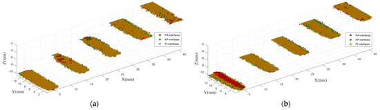
Figure 11.
3D identification imaging results with three classes of interface: (a) PE block sample of metal; (b) PE block sample of carbonization.
5. Conclusions
In this paper, a method based on the THz waves and LSTM classification network was proposed to identify the interface structures inside polymers. LSTM learns from the artificial interface samples firstly, then the trained LSTM is used to identify the internal interfaces from other samples to achieve 3D identification imaging. The experiment results showed that the proposed method could identify the voids interfaces well, while the metal and carbonization interfaces tended to be confused. By combining the metal and the carbonization interfaces as the impurity interface, the identification results were satisfactory.
Author Contributions
Conceptualization, H.M.; methodology, L.W.; software, S.W.; validation, S.W. and H.M.; formal analysis, H.M.; investigation, S.W.; resources, J.L. and D.C.; writing—review and editing, S.W.; funding acquisition, H.M. All authors have read and agreed to the published version of the manuscript.
Funding
This research was funded by the Science and Technology Project of State Grid Corporation (Grant No. 5500-202118134A-0-0-00).
Institutional Review Board Statement
Not applicable.
Informed Consent Statement
Not applicable.
Data Availability Statement
Data presented in this study are available on request from the first author.
Conflicts of Interest
The authors declare no conflict of interest.
References
- Guan, Z.; Liu, Y.; Zhou, Y.; Jiang, Z.; Wang, L.; Shi, W. External Insulation of Insulators and Transmission and Transformation Equipment; Tsinghua University Press: Beijing, China, 2006; pp. 65–86. [Google Scholar]
- Wang, L.; Fu, K.; Mei, H.; Zhang, F.; Guo, C.; Zhang, Z. Influence of environmental humidity on infrared measurement temperature of composite insulators. High Voltage Eng. 2019, 45, 1951–1961. [Google Scholar]
- Wang, S.; Hou, M.; Ma, K.; Li, Z.; Geng, H.; Zhang, W.; Li, N. Research on the Influence of Extremely Cold Environment on the Performance of Silicone Rubber and Fluorinated Silicone Rubber. Polymers 2022, 14, 1898. [Google Scholar] [CrossRef] [PubMed]
- Lennartz-Sassinek, S.; Main, I.G.; Zaiser, M.; Graham, C.C. Acceleration and localization of subcritical crack growth in a natural composite material. Phys. Rev. E 2014, 90, 052401. [Google Scholar] [CrossRef] [PubMed] [Green Version]
- Zhou, L.; Li, T.; Zhou, X.; Guan, W.; Wang, Z.; Wang, S. Statistical Analysis of String Fracture and Core Breakdown of Composite Insulators in Zhejiang Province. In Proceedings of the IEEE Sustainable Power and Energy Conference (iSPEC), Beijing, China, 21–23 November 2019. [Google Scholar]
- Su, C.Q. Failure analysis of three 230 kV XLPE cables. In Proceedings of the Transmission and Distribution Conference and Exposition: Latin America, São Paulo, Brazil, 8–10 November 2010. [Google Scholar]
- Yuan, C.; Xie, C.; Li, L.; Zhang, F.; Gubanski, S.M. Ultrasonic phased array detection of internal defects in composite insulators. IEEE Trans. Dielectrics Electr. Insul. 2016, 23, 525–531. [Google Scholar] [CrossRef]
- Cheng, L.; Liao, R.; Yang, L.; Zhang, F. An Optimized Infrared Detection Strategy for Defective Composite Insulators According to the Law of Heat Flux Propagation Considering the Environmental Factors. IEEE Access 2018, 6, 38137–38146. [Google Scholar] [CrossRef]
- Contin, A.; Schena, G.; Stanic, G.L.; Peruzzi, G. In Inspection of ground-wall insulation for AC rotating machines using X-ray tomography. In Proceedings of the IEEE Electrical Insulation Conference (EIC), Montreal, QC, Canada, 2–5 June 2013. [Google Scholar]
- Qaddoumi, N.N.; El-Hag, A.H.; Saker, Y. Outdoor Insulators Testing Using Artificial Neural Network-Based Near-Field Microwave Technique. IEEE Trans. Instrum. Meas. 2014, 63, 260–266. [Google Scholar] [CrossRef]
- Tzydynzhapov, G.; Gusikhin, P.; Muravev, V.; Dremin, A.; Nefyodov, Y.; Kukushkin, I. New Real-Time Sub-Terahertz Security Body Scanner. J. Infrared Millim. Terahertz Waves 2020, 41, 632–641. [Google Scholar] [CrossRef]
- Tan, X.; Huang, S.; Zhong, Y.; Yuan, H.; Zhou, Y.; Xiao, Q.; Guo, L.; Tang, S.; Yang, Z.; Qi, C. In Detection and identification of flammable and explosive liquids using THz time-domain spectroscopy with principal component analysis algorithm. In Proceedings of the UK-Europe-China Workshop on Millimetre Waves and Terahertz Technologies (UCMMT), Liverpool, UK, 11–13 September 2017. [Google Scholar]
- AlNabooda, M.O.; Shubair, R.M.; Rishani, N.R.; Aldabbagh, G. In Terahertz spectroscopy and imaging for the detection and identification of Illicit drugs. In Proceedings of the Sensors Networks Smart and Emerging Technologies (SENSET), Beirut, Lebanon, 12–14 September 2017. [Google Scholar]
- Geng, Z.; Zhang, X.; Fan, Z.; Lv, X.; Chen, H. A Route to Terahertz Metamaterial Biosensor Integrated with Microfluidics for Liver Cancer Biomarker Testing in Early Stage. Sci. Rep. 2017, 7, 16378. [Google Scholar] [CrossRef] [Green Version]
- Lian, F.; Xu, D.; Fu, M.; Ge, H.; Jiang, Y.; Zhang, Y. Identification of Transgenic Ingredients in Maize Using Terahertz Spectra. IEEE Trans. Terahertz Sci. Technol. 2017, 7, 378–384. [Google Scholar] [CrossRef]
- Yang, X.; Zhao, X.; Yang, K.; Liu, Y.; Liu, Y.; Fu, W.; Luo, Y. Biomedical Applications of Terahertz Spectroscopy and Imaging. Trends Biotechnol. 2016, 34, 810–824. [Google Scholar] [CrossRef]
- Ellrich, F.; Bauer, M.; Schreiner, N.; Keil, A.; Pfeiffer, T.; Klier, J.; Weber, S.; Jonuscheit, J.; Friederich, F.; Molter, D. Terahertz Quality Inspection for Automotive and Aviation Industries. J. Infrared Millim. Terahertz Waves 2020, 41, 470–489. [Google Scholar] [CrossRef] [Green Version]
- Zimdars, D.; Valdmanis, J.A.; White, J.S.; Stuk, G.; Winfree, W.P.; Madaras, E.I. In Time domain terahertz detection of flaws within space shuttle sprayed on foam insulation. In Proceedings of the Conference on Lasers and Electro-Optics/International Quantum Electronics Conference and Photonic Applications Systems Technologies, San Francisco, CA, USA, 16 May 2004. [Google Scholar]
- Mei, H.; Jiang, H.; Yin, F.; Wang, L.; Farzaneh, M. Terahertz Imaging Method for Composite Insulator Defects Based on Edge Detection Algorithm. IEEE Trans. Instrum. Meas. 2021, 70, 1–10. [Google Scholar] [CrossRef]
- Jiang, H.; Mei, H.; Bian, X.; Li, L.; Wang, L.; Wang, L. In Detection of Double-layer Air Gap Defects Based on Terahertz Imaging Method. In Proceedings of the IEEE International Instrumentation and Measurement Technology Conference (I2MTC), Glasgow, Scotland, 17–20 May 2021. [Google Scholar]
- Zhang, Z.; Peng, G.; Tan, Y.; Pu, T.; Wang, L. THz wave detection of gap defects based on convolutional neural network improved by residual shrinkage network. CSEE J. Power Energy Syst. 2020, 1–10. [Google Scholar] [CrossRef]
- Lai, C.F.; Chien, W.C.; Yang, L.T.; Qiang, W. LSTM and Edge Computing for Big Data Feature Recognition of Industrial Electrical Equipment. IEEE Trans. Ind. Inform. 2019, 15, 2469–2477. [Google Scholar] [CrossRef]
- Li, D.; Zhang, Z.; Liu, P.; Wang, Z.; Zhang, L. Battery Fault Diagnosis for Electric Vehicles Based on Voltage Abnormality by Combining the Long Short-Term Memory Neural Network and the Equivalent Circuit Model. IEEE Trans. Power. Electron. 2021, 36, 1303–1315. [Google Scholar] [CrossRef]
- Sun, F.; Fan, M.; Cao, B.; Zheng, D.; Liu, H.; Liu, L. Terahertz Based Thickness Measurement of Thermal Barrier Coatings Using Long Short-Term Memory Networks and Local Extrema. IEEE Trans. Ind. Inform. 2022, 18, 2508–2517. [Google Scholar] [CrossRef]
- Kniffin, G.P.; Zurk, L.M. Model-Based Material Parameter Estimation for Terahertz Reflection Spectroscopy. IEEE Trans. Terahertz Sci. Technol. 2012, 2, 231–241. [Google Scholar] [CrossRef] [Green Version]
- Dhillon, S.S.; Vitiello, M.S.; Linfield, E.H.; Davies, A.G.; Hoffmann, M.C.; Booske, J.; Paoloni, C.; Gensch, M.; Weightman, P.; Williams, G.P. The 2017 terahertz science and technology roadmap. J. Phys. D Appl. Phys. 2017, 50, 043001. [Google Scholar] [CrossRef]
- Duvillaret, L.; Garet, F.; Coutaz, J. A reliable method for extraction of material parameters in terahertz time-domain spectroscopy. IEEE J. Sel. Top. Quantum Electron. 1996, 2, 739–746. [Google Scholar] [CrossRef] [Green Version]
- Liu, Y.; Su, Z.; Li, H.; Zhang, Y. In An LSTM based classification method for time series trend forecasting. In Proceedings of the IEEE Conference on Industrial Electronics and Applications (ICIEA), Xi’an, China,, 19–21 June 2019. [Google Scholar]
- Ueta, G.; Wada, J.; Okabe, S.; Miyashita, M.; Nishida, C.; Kamei, M. Insulation characteristics of epoxy insulator with internal void-shaped micro-defects. IEEE Trans. Dielectr. Electr. Insul. 2013, 20, 535–543. [Google Scholar] [CrossRef]
- Chen, X.; Xu, Y.; Cao, X.; Gubanski, S.M. On the conducting and non-conducting electrical trees in XLPE cable insulation specimens. IEEE Trans. Dielectr. Electr. Insul. 2016, 23, 95–103. [Google Scholar] [CrossRef]
- Li, S.; Wang, W.; Yu, S.; Li, J. Degradation of cross linked polystyrene by repetitive impulse surface flashovers in vacuum. IEEE Trans. Dielectr. Electr. Insul. 2013, 20, 1934–1941. [Google Scholar] [CrossRef]
- Tang, J.; Wang, L. In Research on the Discharge between High—Voltage Cable Metal Sheath and Insulation Shield. In Proceedings of the IEEE Conference on Industrial Electronics and Applications (ICIEA), Xi’an, China, 19–21 June 2019. [Google Scholar]
- Florkowski, M.; Florkowska, B.; Rybak, A.; Zydron, P. Metal migration at conductor / XLPE interface subjected to partial discharges at different electrical stresses. IEEE Trans. Dielectr. Electr. Insul. 2015, 22, 456–462. [Google Scholar] [CrossRef]
- Zhang, T. Research and Application of High and Extra High Voltage Super-Clean Cable Material. Master Thesis, Harbin University of Science and Technology, Heilongjiang, China, 2016. [Google Scholar]
- Wietzke, S.; Jansen, C.; Reuter, M.; Jung, T.; Kraft, D.; Chatterjee, S.; Fischer, B.M.; Koch, M. Terahertz spectroscopy on polymers: A review of morphological studies. J. Mol. Struct. 2011, 1006, 41–51. [Google Scholar] [CrossRef]


Publisher’s Note: MDPI stays neutral with regard to jurisdictional claims in published maps and institutional affiliations. |
© 2022 by the authors. Licensee MDPI, Basel, Switzerland. This article is an open access article distributed under the terms and conditions of the Creative Commons Attribution (CC BY) license (https://creativecommons.org/licenses/by/4.0/).